People are often startled and intimidated when they discover that a 3D printer is not really the same as a paper printer. Although some consumer 3D printers have a “print” button, there are some steps needed to get to the point of pushing it, not to mention the need to monitor what happens afterwards. We prefer to think of 3D printing as more like cooking than printing. Just as you would not expect to cook by just pressing a “bake” button without setting some temperatures and timers first, 3D printing requires some knowledge of your printer, the materials you are using, and the design you are trying to print. If any of those have issues, getting good results is challenging.
As happens with cooking, everyone wants to start out creating a multitier wedding cake. However, it is wise to try for brownies instead, at least for a while. In this chapter, we help you understand what is hard to print versus what is easy, and give you some insight into more sophisticated techniques. Different printers have evolved variations on the basic workflow. Some are the equivalent of an Easy-Bake Oven, whereas others are like equipment in a commercial kitchen, for similar reasons of capability versus complexity. Your expectations need to match your hardware. Price is not always a guide to capability and quality in the current market; see Chapter 4’s discussion on how to buy a printer.
As you will see, unlike with cooking, some basic computer skills are necessary to get started. This chapter walks through the steps needed to go from zero to plastic in as generic a way as possible, with some nods to common variations on the theme. 3D-printing software is updated often, so the precise options we show here may change by the time you read this. The overall workflow should stay much the same, though. For that reason, we have just a few screenshots and narrate the types of printer settings rather than go step-by-step through any particular program.
Workflow Overview
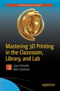
3D printing typically requires three steps (Figure 3-1) that might be combined into fewer than three pieces of software, might require some scrolling around on a screen on your printer for the last step, or might involve other variations. In all cases, though, you need to create or acquire a 3D computer-aided design (CAD) model, slice this model into layers and generate the commands needed to physically create the model, and, finally, physically create the print.
3D-printing workflow
Note
For historical reasons, people sometimes refer to the set of software that runs an automated tool like a 3D printer as its toolchain . The word does not imply any physical objects—in the case of a 3D printer, at least. We use the word workflow here, which we feel may be more familiar in educational or scientific settings.
Models
The first step in the 3D-printing process is developing a 3D model of the design you want to create. This is done in CAD software, which we introduce here and explore in depth in Chapter 6.
Types of 3D-Printable Files
Typical consumer 3D printers want a model to be in stereolithography (STL) format. This format is quite old and inefficient, but universal. When software generates an STL file, it converts the surface to a mesh of triangles. An STL file consists of a giant list of the coordinates of the three vertices of each triangle in 3D space, and the orientation of the normal vector to the plane of that triangle.
A similar standard supported by many slicers is an OBJ file, an open format originally developed by Wavefront Technologies that also supports texture mapping for color and NURBS curvature, though use of these features is rare and they are ignored by slicers if present. A superset standard that can be a grouping of multiple STL files is an additive manufacturing (AMF) file, which also supports material definitions required for printing with multiple filaments (for different colors or different material properties). More recently, Microsoft has formed a consortium to introduce the 3D manufacturing (3MF) format, which has similar capabilities (for more, see https://3mf.io/what-is-3mf/).
File Repositories
The other way to get an STL file is to download one that someone else has already created. Many repositories are full of files that people have put out for free, including www.thingiverse.com , www.youmagine.com , www.instructables.com , and www.pinshape.com . There are repositories on www.github.org that include 3D-printable models as well.
For better or worse, these repositories are populated by anyone who wants to post something. Although many of the designs are amazing, some of the objects may never have actually been printed, or the designer might be nine years old and posting for fun without any idea of what is printable. Models for education might or might not be accurate. So if you use one, be sure to review it and read the license that spells out how you are allowed to use it.
Creative Commons Licenses
3D-printing software and models are often released under a creative commons license , which you might encounter in the form of notations like “Released under a Creative Commons 4.0 International license, CC-BY-NC-SA,” typically including a link to the relevant license text at www.creativecommons.org .
Use your material (CC, creative commons)
As long as they attribute it to you in a certain way (BY )
And do not use it for commercial purposes (NC )
And anyone who uses your materials must release their materials (including the part you contributed) under the same license (SA, for share alike)
Deciding how to release and use materials is complex, and you should consult a lawyer versed in software intellectual property if you are embarking on a major project, particularly if money and friendships are involved. The Creative Commons website is a good and lucid place to get some background first, though.
Many 3D printers have heritage to the RepRap project ( www.reprap.org ), which is an ongoing project to build an open source community of creative commons hardware and software. These printers are typically referred to as open source printers.
Tip
Chapter 5 includes a quick-start guide that talks you through how to create a small cube as a test. You can use that as a first test model and then move on to more complex things in Chapter 6. It may be tempting to download something from a repository and try that first, but if you have issues, you will not know if it is a printer problem or a model that has issues.
Scanning
Consumer-priced 3D scanners either require you to take multiple pictures from multiple angles or scan using a device that produces multiple laser beams or some other structured light pattern. Either way, you typically end up a lot of artifacts that have to be cleaned up manually in software, a process that can be tedious and time-consuming. Typically, people use a scan as a starting point for what they are doing or a dimensional reference and then draw over it in a CAD program to correct and clean up the scan. Software is the hard part of 3D scanning, and some professional scanners have software to automate some of this, but as of this writing these packages tend to cost many thousands of dollars. Figure 3-2 shows a 3D print of Rich, based on a scan made with a DIY scanner.
Tip
If you would like to build your own scanner, there are open source designs out there, like the Cyclop 3D scanner (an open hardware scanner for small objects built with 3D-printed parts that uses open source software) and Skanect (software that allows you to repurpose an Xbox Kinect for human-scale 3D scanning).

Scanned and 3D printed sculpture
Slicing Software: Filament Printers
3D printers cannot use a CAD output file (that is, an STL file) directly. A piece of software known as a slice engine has to take the STL file and figure out the commands that the 3D printer will execute a layer at a time. Slice engines might be in freestanding programs, or combined with other relevant software in the 3D-printing workflow. We call programs containing one or more slice engines slicing software .
Tip
If you come into this from a machine-shop environment, slicing software can also be thought of as computer-aided manufacturing (CAM) software.
Slicing programs use different settings to allow for variations in the geometry of the printer, the type of filament you are using, and so on. Resin and other technologies are philosophically similar, but the differences are big enough that we talk about them in a different section of this chapter. In this section, we focus on filament printers.
There are many different slicing engines out there now. In most cases they are freestanding programs or code embedded in programs that are proprietary to a particular printer. Because getting all the settings right for a particular 3D printer can be fiddly, a lot of manufacturers modify one of these open source programs and create a proprietary program just for their machine. However, many printers can still use the basic open source program. We will describe several of those programs here, and go over some of the commonest 3D-printer settings and what they control.
Some of the more common, freely available programs are Slic3r, Cura, and MatterControl. Printers built around open source standards will often make a file of settings for one of these programs available, or create a custom program around one of these slicing engines.
Tip
Most slicing software allows you to simulate what the printer will do during your print with a graphic to step through the layers, and in some cases to simulate within a layer. Be sure to use this feature to walk through every print. It will save you a lot of grief and filament. We show some examples of this later in the chapter.
Slic3r
Slic3r (pronounced “slicer”—the 3 is silent) has been around for a long time and is maintained by an open source community led by Alessandro Ranellucci. Its slicing engine has been incorporated into other programs over time. Slic3r has a reputation for getting cutting-edge functionality first, which always has pluses and minuses. You can download it at www.slic3r.org .
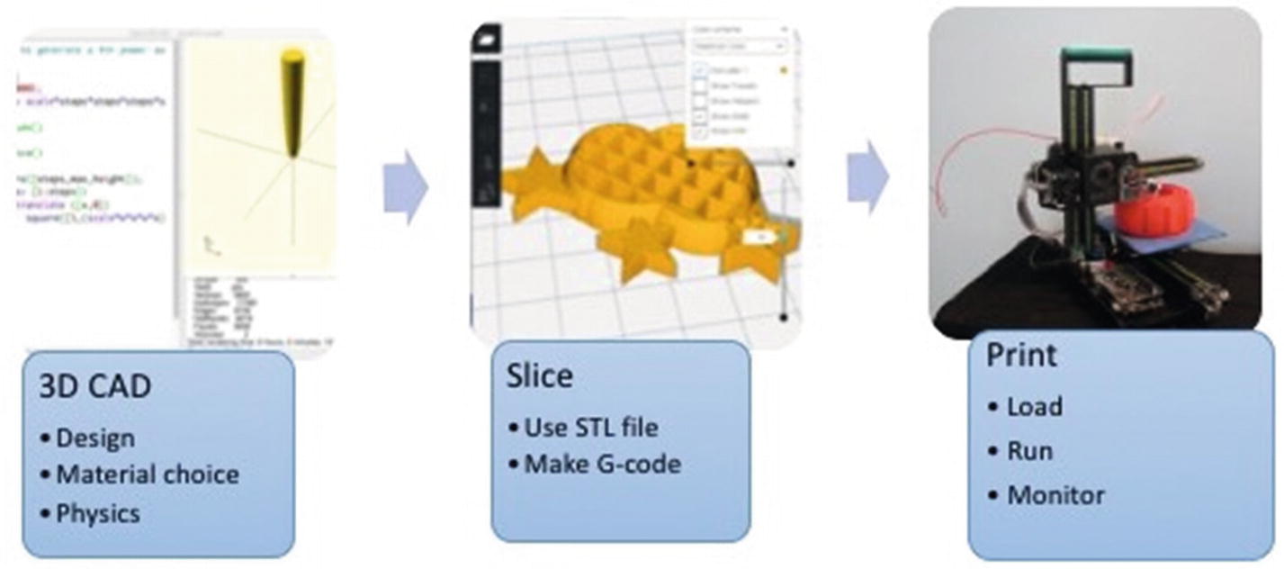
MatterControl
MatterControl ( www.mattercontrol.com ) is a free program maintained by 3D printer retailer MatterHackers. As of this writing, it is in the process of a major upgrade to version 2.0. Version 1.x combined access to Slic3r, Cura, and its own slicing engine, MatterSlice. MatterControl 1.x is also a host program that allows users to send single commands to a printer, jog axes, and change extruder temperature. The update to 2.0 is planned to include a minimal CAD program as part of the front end, and a simplification to just its own slice engine.
Screen shot of MatterControl 1.7
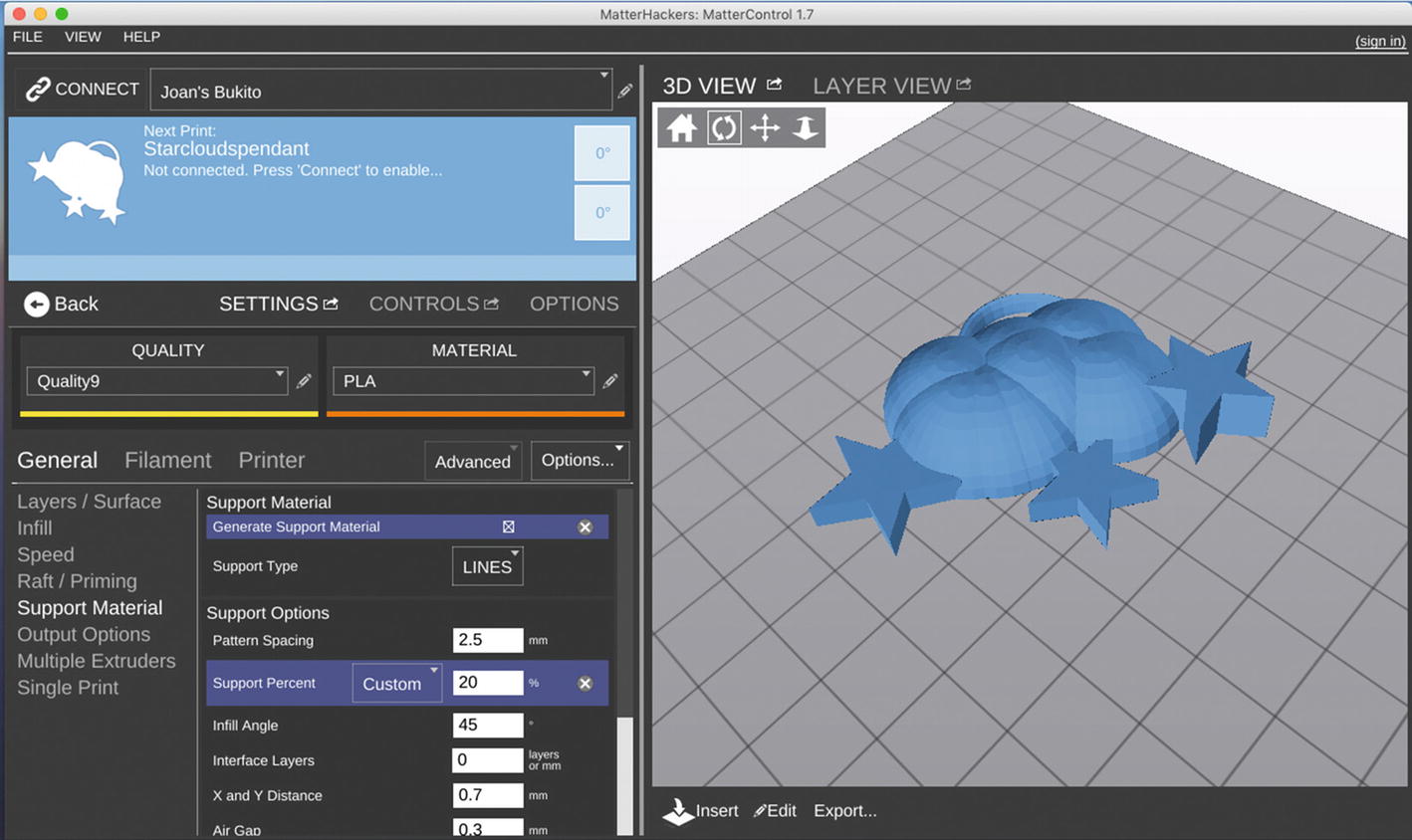
Ultimaker Cura 3
Utimaker Cura 3 is maintained as an open source program by 3D manufacturer Ultimaker, and can be downloaded from https://ultimaker.com/en/products/ultimaker-cura-software . In 2017 a major update to Cura 3.0 added many different control options to fine-tune prints. We will use Ultimaker Cura 3 for the rest of the screenshot examples in the “Using a Slicing Program” section of this chapter, with the kind permission of Ultimaker.
Note
In the past, Cura numbered its releases based on the year of release, ending in 2015 (Cura 15.x), and then changed numbering to Cura 2 and now Cura 3. Several 3D printer companies based their software on one version or other of Cura 15, so that version will be around for a while. Cura 15 is a lot simpler but very robust. The main point here is that Cura 15 is several years older than Cura 3.
Other Programs
The proliferation of 3D printers has been accompanied by a flurry of slicing programs. Some manufacturers (like Makerbot) have their own proprietary software. There are also printer-agnostic third-party programs out there, like Simplify3D, which is a powerful (but not free) program that also has some editing and mesh repair functions.
Using a Slicing Program
Slicing programs typically require that you give the program both some information about your 3D printer’s geometry (the size of the print bed, whether it is heated or not, how tall a print can be, what size filament it uses, and so on). Often this is a file of some sort that your manufacturer will provide. If not, you will have to guesstimate as best you can. Failing that, you can always try the default settings in a slicer. Documentation on the download site for the slicing program you select should walk you through that. Once you have defined your printer, you will be facing the daunting list of settings to select.
Different programs may call similar settings by different names, and may change those names over time. We will not walk through step-by-step screen shots here, since by the time you read this they may well have changed. Instead, we will talk about the big groups of settings that you will need to think about, and what these settings do.
Example: Ultimaker Cura 3
We give a general introduction to slicer settings here using Ultimaker Cura 3. Like most slicing programs it requires you to input some information about your printer, then make some selections that are related to the material you are using, and then finally tweak some settings that might vary model to model.
Because there are dozens of settings (and because hovering over any setting in Custom mode gives you an explanation), we do not go through them exhaustively here. Rather, we suggest good ways to get started and then talk about exceptions and case studies in the later chapters of this book.
To get started, in the menus at the top of the opening screen, click Settings ➤ Printer ➤ Add Printer. Unless you have an Ultimaker, click Other to see if your make and model is listed. If not, click Custom. A first window labeled Printer will come up; input the dimensions (in millimeters) of your printer and whether or not it has a heated platform. Then click the Extrude tab at the top of the window and input nozzle diameter and “compatible material diameter,” which most other software would call “filament diameter.” Start with either 2.85 for “3 millimeter” filament, or 1.75 for anything else. Save those settings, and then you will see a screen that looks something like Figure 3-4, but without a model displayed in the window.
Opening screen for Ultimaker Cura 3, basic setting
Tip
We use the names of settings in Ultimaker Cura 3 in this discussion; if you use different software, the names might be a little different. Where similar settings have very different names in different common slicers, we will try to mention the other names you might want to look for. We have case studies scattered throughout the later chapters of this book. In this chapter we focus on the major slicer settings that you are likely to need to worry about often.
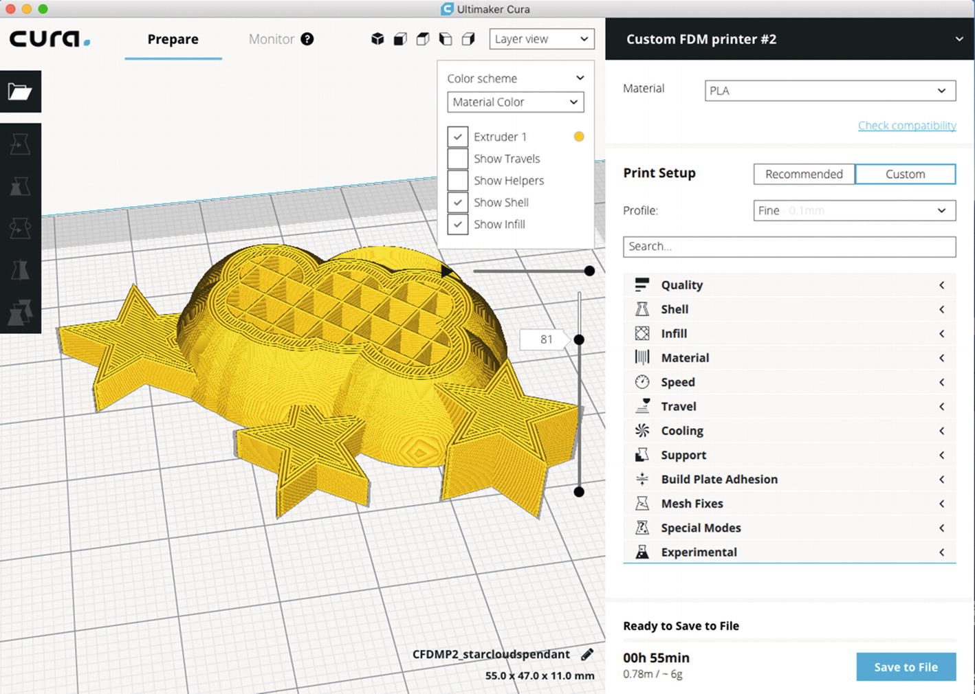
Custom settings screen for Ultimaker Cura 3
Simulating Your Print
You can see one of the most important tools in a slicer in Figures 3-4 and 3-5: the ability to simulate how your print will build up layer by layer. If you select Layer View from the pulldown menu above your print, you will be able to drag around sliders to move within a single layer, or from one layer to the next. Even if you are an advanced 3D printer user, it is always a good idea to walk quickly through a print to see if you forgot something, or if something does not look remotely like you expected. In particular, look at the very first layer of your object (the first layer beyond the raft, if you are using a raft—see the discussion about rafts that follows) because if pieces are missing, your print will likely fail.
Print Quality and Layer Height
3D printers print each layer in one plane parallel to the build platform and then step up and do the next layer. The extruder head moves upward, away from the platform, after completing each layer. The two axes in the plane of the platform are referred to as x and y, and the vertical axis is the z-axis, as we describe in Chapter 2. Layer height is defined as the thickness of the material in each step up of the z-axis. In Chapter 8 we discuss how to get as smooth a surface as possible.
Caution
Layer height has to be less than (not equal to!) the nozzle diameter. About 80% of the nozzle diameter is a good maximum value for layer height. Minimum layer height is not really dependent on the nozzle, and is determined by other factors. We talk more about layer height and surface smoothness in Chapter 8.
Shells
In an STL file , the surface is represented by a mesh of triangles. The slicer produces surfaces facing the sides with one or more perimeters around each layer, and surfaces facing up or down with solid layers (or solid areas of layers). The space inside this outer surface is then partially filled in to make the object stronger and to create a base for the next layer. The perimeters and solid areas are called the print’s shell . The material that the slicing software will create for the interior support is called infill.
Your slicer will allow you to specify the thickness of the horizontal shell, either as a number of perimeters or in millimeters (which will be rounded to a multiple of your perimeter extrusion width). Two is typically a good number. The width (in the x-y plane) of this perimeter is the extrusion width, which must be no smaller than your nozzle diameter, and might be larger.
You can similarly set the thickness of the vertical shell, which your slicer might offer as a setting in millimeters or a number of top/bottom solid layers, or both. You will generally want at least three or four layers to avoid gaps. Setting the thickness in millimeters can be advantageous because it allows you to match your horizontal shell thickness when changing layer heights, and because very thin layers often have more trouble bridging over infill, so they may need the extra layers to smooth themselves out.
Platform Adhesion
One of the challenges with a 3D printer is getting the model to stick to the platform. Sometimes a model has a relatively small contact area with the platform, and when the extruder lays down the next layer it knocks the model loose. When that happens, the plastic that is intended to make up subsequent layers falls in random places as the structure gets knocked around. The resulting mess is typically called printing hair (in polite company, anyway). There are few worse feelings than smugly demonstrating a 3D printer to your friends and then noticing that your model is being merrily dragged around the platform, trailing strands of filament. Techniques to prevent such bad hair days follow.
Brims
A brim expands the first layer by creating additional perimeters to increase contact area with the platform, and is intended to be peeled away along the edge of the print’s base. A brim usually is specified in terms of width away from the object. A few millimeters usually make a big difference. Figure 3-6 shows a brim stabilizing a print.
Note
Experts often make the first layer of a print a lot thicker than subsequent layers. A thick layer plus a brim can make it a lot more likely a print with a small contact area will survive to the end.
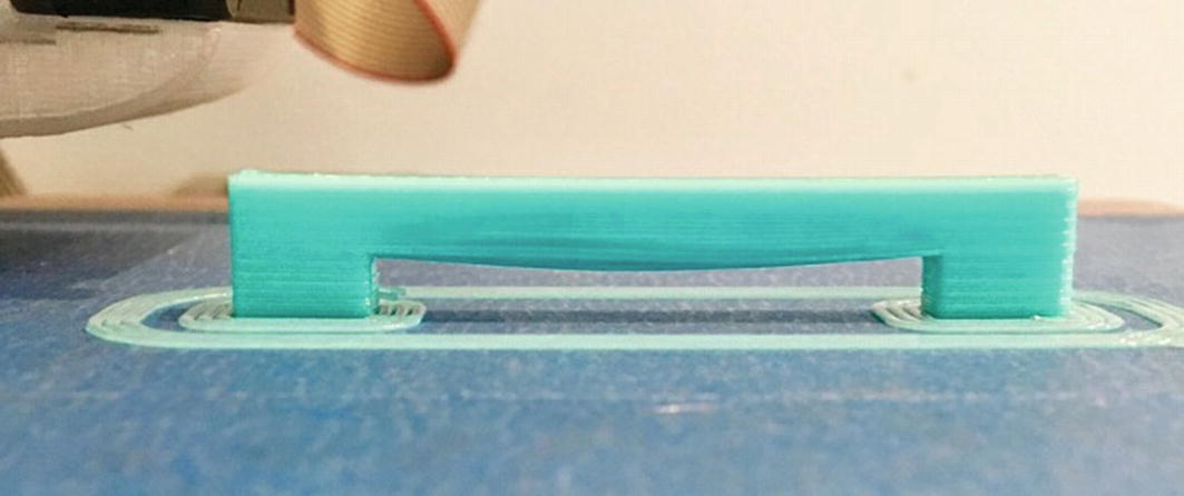
A brim, skirt, and some bridging
Skirts
A skirt is a few loops of filament laid down at the beginning of a print that outline all the objects being printed at a given time and show the maximum size of the first layer of the print. You can see one in Figure 3-6; it is the double line that does not touch the print. A skirt can solve several problems that might be encountered at the very start of a print.
It is possible to print more than one thing at a time on a 3D printer’s platform. The programs for arranging the objects for a print run show you where the prints will be positioned relative to each other. However, it is always possible to create something that would wind up too big to print, since the (virtual) version can be hanging off the platform. When the skirt is drawn around all the objects that you are planning on printing, it allows you to quickly see whether there are any problems so you can stop the print right away.
Also, if you have just switched filaments from one color to another, it is good to print something away from your object first so that any material of a different color that is still in the nozzle is melted out before starting to print the main object. Plastic may also ooze out of the nozzle after a print, or while heating up for the next one, which can leave a void that causes a delay before plastic starts coming out again. Generally, a skirt allows the printer to finish filling the extruder with filament (known as priming) before the main object starts printing.
The skirt is usually a few millimeters away from the location on the platform where the first layer of the main object being printed will reside. By the time a few loops are done, any previous filament should also be flushed out of the nozzle. Most programs allow the user to specify both the distance that the skirt is from the main model and the number of loops constituting the skirt.
Tip
Add a few loops to the skirt when you change to a light-colored filament after printing a previous print with a dark filament. Doing so clears out the nozzle so there will not be any mixing of colors and resulting staining of your print.
Rafts
When you look at the lists of settings in a slicing program you may see options for a raft. A raft is a few layers of support material underneath a print. In the early days of 3D printing, when beds were often uneven and there were no heated platforms, rafts could help prints stick better. This practice has largely gone out of favor since a good first layer and perhaps a brim are a better combination on a modern printer.
A raft is a good solution if a print does not have many contact points with the bed and you want to be sure it will not fall off—for example, a large object that you do not want to fail midway through a 12-hour print. Rafts are also useful if you need the bottom surface to be dimensionally accurate, since direct contact with an uneven platform can leave it slightly skewed or not entirely flat.
The bottom layer of a raft is printed with extrusion lines that are not only taller than a normal layer, but wider so that they have more contact area with the platform. The larger volume of plastic being pushed out of the nozzle also makes the print less sensitive to being a little too far from the platform surface in some areas, whereas having the nozzle further from the surface reduces the risk of jamming the extruder or even damaging the nozzle or the platform by getting too close in others.
Modern slicers give you the ability to do this without a raft by using a setting called “initial layer line width” or “first layer extrusion width.” In conjunction with the initial layer height setting, this allows you to configure the first layer of your print to stick like a raft’s base layer, without the added time or wasted plastic. Because you will be putting out a lot more plastic at once, it a good idea to slow this layer down significantly if you are going to use these features, to prevent jams, and slower printing is good for first layer adhesion anyway. If you are using these features and decide that a print needs a raft, be sure to set them closer to your normal printing settings—otherwise you will be increasing adhesion to the raft, and you may not be able to get it off!
Supporting and Orienting a Model
Consumer 3D printers build up their models from a platform, whether the extruder is fixed and the platform drops away or the extruder head moves up and away from a platform. This means that in some cases, a print head would be laying down material in air. For example, imagine a statue with an outstretched arm. Assuming that the statue is being printed up from its base, the initial bottom layers of the arm would print into the air and fall down unless something was printed into the open space all the way up from the platform. Material printed like this is called support. Sometimes this problem can be minimized or eliminated altogether by printing the model in a different orientation. This section talks about these interacting considerations.
Support
In a 3D print, the first layer sticks to the platform. Then the second layer is added above that, and so on, like a brick wall. The printer depends on having something below the nozzle to compress the extrusion against, much like the mortar between bricks. In the case of the wall, if there are no bricks under the second layer (or at least some bricks partially lapped under it), the second layer of brick will fall to the ground. If you want to lay bricks across the top of an opening in the wall, like a window or doorway, you need a scaffolding to support them as you are building. (For exceptions to this, see the section on bridging later in this chapter.)
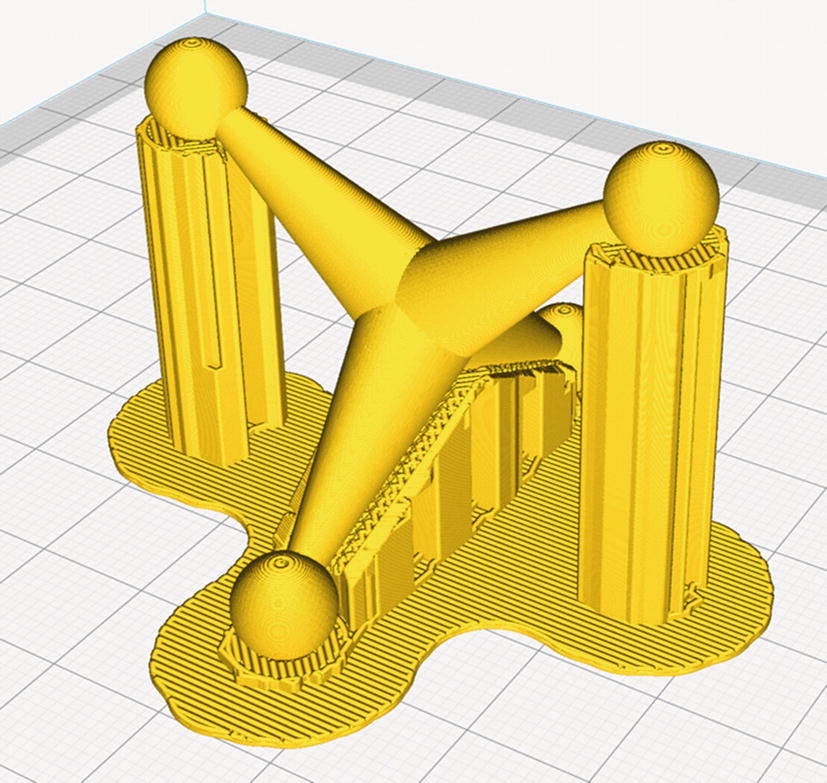
A model with support
Orientation
A particular model may seem to have a side that is “supposed” to be the bottom of the model. Sometimes, though, turning a model so that it lies on its side or even upside-down can increase the first-layer contact with the platform and decrease the amount of support. Particularly if you are going to be printing the object more than once, spending some time playing with the orientation of a complex model is worthwhile.
A bit of thought can sometimes also eliminate support that the slicing software would automatically create in hard-to-get-at places, like internal narrow spaces. Sometimes turning a complicated object through some arbitrary rotation—for example, 10 degrees about the x-axis, and 15 degrees about the y-axis —will result in the best situation with the least support needed.
Printers that can only use one filament at a time print support in the same material as the rest of the model. Printers that have multiple extruders can lay a dissolvable filament, though this process is often more costly, time-consuming, and error-prone than using your print material.
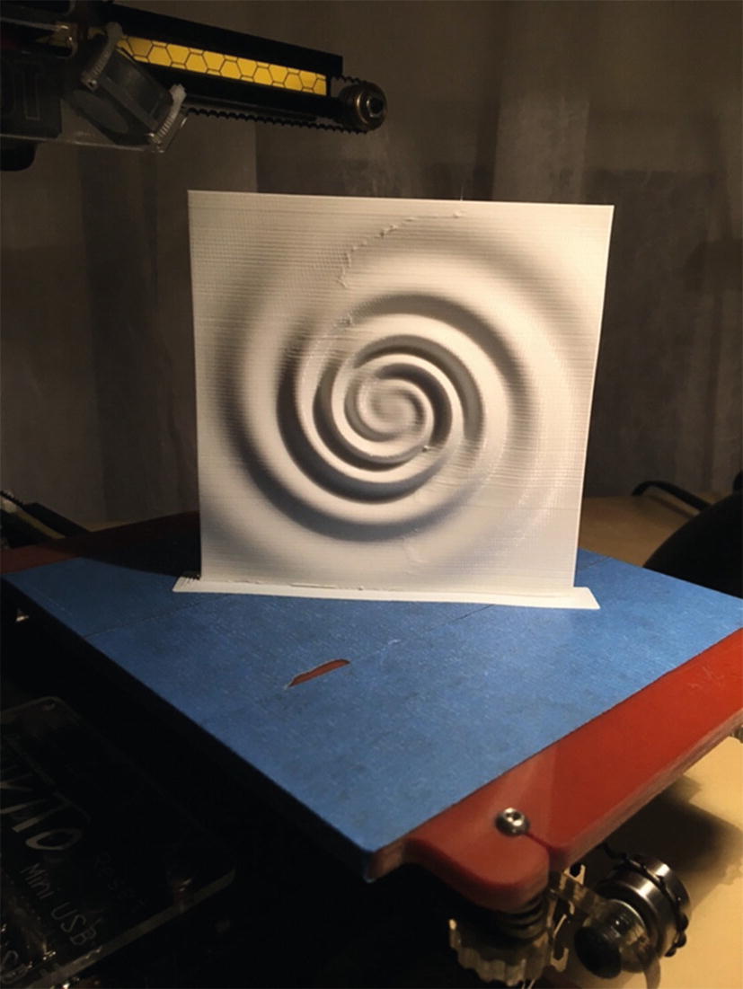
Gravitational wave model, printed vertically
Avoiding Support by Cutting a Model into Pieces
For an object with a complex surface that requires support, sometimes you can cut the object into two or more pieces, print the pieces cut-side-down, and then glue the parts together later. Some CAD programs have tools to make this sort of cut. If the program you are using does not, there are a few free or open source programs that allow the user to rotate an object around all three axes and then make a cut along a resulting convenient axis. Because this is a rapidly evolving area, search online for “cutting STL files free software.” Often printed support can be avoided entirely with one judicious cut. After printing, the halves will have to be glued together. Chapter 8 discusses paint, glue, and finishing.
Managing Internal Open Space
Just as there is open space around the outside of a model (like the statue’s outstretched arm mentioned earlier) similar problems arise inside a model or in space enclosed by a model. Imagine a closed box: it would need some sort of support to run between the top and bottom. This support is called infill . Sometimes it is not necessary to have infill everywhere, and you can get away with just stringing filament across (usually) small gaps, a process called bridging. This section gives you some ideas about the design issues that arise with internal support.
Bridging
It is possible to bridge across open areas in a model without support if the open area is not too wide (say, less than 20–30 mm, depending on your printer’s cooling fans and other factors). There are several schools of thought about the best settings to use when bridging across a gap. On the one hand, having the printer move more slowly than usual while trying to increase filament flow rate slightly may result in the bridge sagging a little. Conversely, having the printer move faster and push out less may mean the filament will not stretch enough to cross the open area and will break. Finding an optimum between the two requires some experimentation with your printer.
Some slicing programs have settings for adjusting speed and flow of plastic specifically for bridging. Defaulting these settings to the rate the slicing program creates is a good place to start.
Another way to get around bridging is to terrace or arc under the bridged area so that the printer is in fact just climbing a 45-degree (or shallower) slope underneath. An overhang climbing at about a 45-degree angle is about the limit that can be consistently printed without support. However, sometimes a steeper slope will work with some combinations of settings; a bit of experimentation is often worthwhile to avoid needing to use support, particularly in a complex structure. If bridges are too long, though, as with the print in Figure 3-6, the bridge may sag a bit or have drooled bits of filament on it.
Infill
Users of 3D printers do not usually want to create solid objects, because that uses a lot of filament. However, typically objects cannot be hollow, either, because upper layers would be printed in air. (Exceptions to this are discussed in Chapter 8.) As a result, most slicing software creates internal support called infill inside the solid surfaces of an object to minimize filament use (as well as to make the print faster). Figure 3-9 shows typical infill patterns.
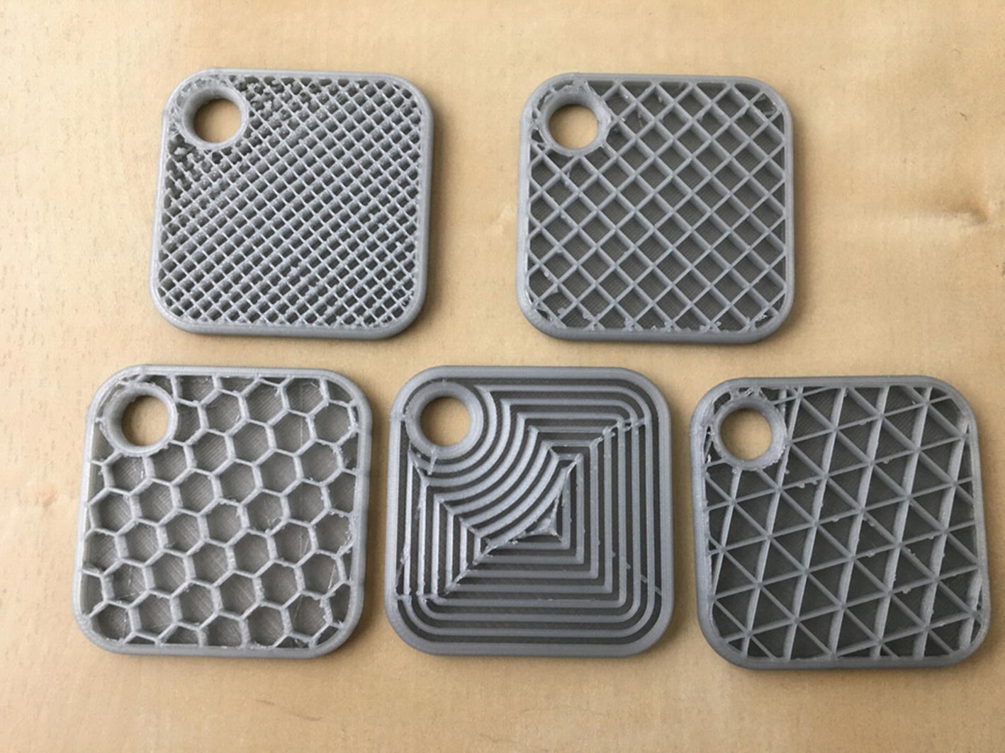
Typical infill patterns
Print infill is usually specified in terms of percentage fill. So, 12% infill means that 12% of the interior volume of the object will be occupied by material and 88% will be open. (This percentage does not include the outer perimeter of the print.)
Although infill adds some strength by bracing the interior of the object against collapsing, most of the print’s strength comes from the solid surfaces, and if you want to make a print stronger, it is usually better to increase the thickness of the skin rather than increasing infill. Compared to printing completely hollow, infill is more important for its ability to act as a support structure for a model’s internal overhangs, to prevent sagging or gaps in the top surface of a print. Most slicers have some more exotic options for infill patterns, but unless you are printing with a highly transparent filament, these patterns are unlikely to be visible once the print has finished.
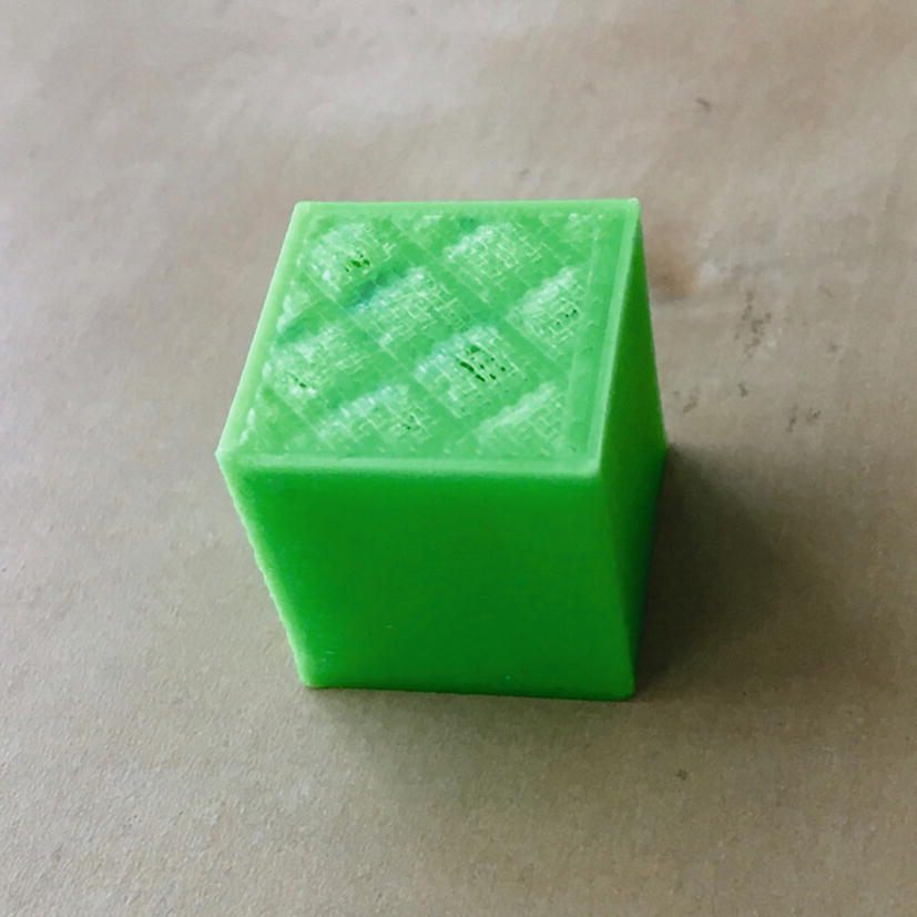
Pillowing on a 20 mm cube
Although there are now some infill patterns that are designed to create 3D structures within a model, most are the same every layer or print in different directions on alternating layers. This means that the shape and size of the gaps between lines will be consistent when they intersect with the top and bottom surfaces. But why do those surfaces need to be solid? If you think of a square filled with a grid of squares, it would be fairly easy to crush that shape by applying force to opposite corners. You can brace it with a triangular grid instead, but filling the front and back faces is even more effective, so strength is rarely a big factor in the choice of infill patterns.
There is such a thing as a print created without top and bottom solid layers. Vase mode prints (Chapter 8) omit the infill and top layers to turn a solid model into a vessel that is open on top.
Note
Printing solid (100% infill) is a special case, and we discuss the issues and printer settings relevant to that in Chapter 8.
Retraction and Stringing
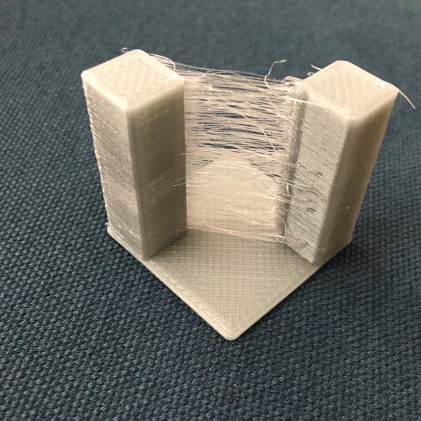
Stringing
Retraction is typically handled as an automatic feature in slicing software with some limited user control. In Cura, there are many settings to fine-tune retraction under the Material heading. Also, in the Travel section, you can tick a box to allow combing . This is a way to avoid retracting if printing sparse or complex infill might otherwise require it. It does not matter if infill strings a bit, because it will only be visible inside the model when the model is complete. Doing a lot of retraction can wear on the filament in some printer configurations and slows down the printing process, so avoiding it where possible is a big plus.
Temperatures
You may find that you need to tweak settings as you print in different materials. The temperature of your extruder (and your heated build platform, if yours has a heater) will vary with the materials. In Chapter 2 we talked about the requirements for several common materials. The reality is that every time you use a new brand (or even color) of filament, you may need to experiment a bit.
In Cura 3, temperatures are under the Materials section. There are a bunch of temperatures you can change, but to start just make them all the same as each other. Filament spools usually suggest a temperature range. In the absence of other information from your experience or manufacturer, just start in the middle of the range. Too hot can result in stringing or blobby prints; too cool can result in poor adhesion between layers and the platform or between two layers.
Be sure that your nozzle and platform can handle the temperature you are asking them to reach. Printers have very limited error checking, and it is possible to damage your printer by telling components to get hotter than they are rated for.
Speeds, Cooling, Extrusion Multipliers
Your slicer will include several settings for speeds of a print. Unless the slicer specifies otherwise, all of its speeds are speeds of linear motion. This is the maximum speed that the printer will move for this portion of the print, but acceleration my not allow it to reach that speed, and cooling settings may also limit it.
Travel speeds control how fast the printer moves when it is moving between parts without extruding. This should generally be set as fast as the machine can handle, since going slower will not only increase print time, it will allow more time for plastic to ooze out of the nozzle in areas where you do not want it.
Most slicers also include several different printing speeds. Perimeters, infill, and solid surfaces all generally have their own printing speeds. You may be tempted to speed up your print by printing the infill quickly and slowing down the outer perimeters to get smoother motion—be careful, because residual pressure in the nozzle might cause a blob where the perimeter starts. The one place it is always good to set a slower speed is for the first layer, because slowing it down helps with platform adhesion and reduces the chances of something bad happening if the platform is not aligned perfectly.
In Cura 3, the Minimum Layer Time setting tells the slicer to reduce speeds if a layer will take less than the specified time to complete. This is done to allow time for the plastic to cool before printing another layer on top of it. If the plastic does not cool sufficiently, you can get a misshapen blob of plastic instead of the fine features of your model. There are also settings to control the speed of fans pointed down at your print. Depending on the strength of your fans, you may be able to cool the plastic faster, allowing lower values for minimum layer time to be used.
If your print has a single narrow feature at the top, minimum layer time might not be able to do its job because the plastic stays in contact with the hot nozzle and does not have a chance to cool. In this case, printing two of your object at once or adding a cylinder the same height as your print (known as a cooling tower) will give the printer something else to do so that it moves away from that feature and allows it to cool properly.
The speed at which plastic is pushed out is controlled by the combination of this speed and the specified layer height and extrusion width according to a calculation of volume. The slicer needs to know the diameter of the filament so it knows how much volume of plastic is in one millimeter of it. If this calculation results in the wrong volume of plastic, usually because the extruder is not properly calibrated, the Flow setting, otherwise known as an Extrusion Multiplier, gives you a fudge factor to tweak this calculation .
More Exotic Settings
Settings often interact with each other, and the details of a particular case matter. We have relegated talking about some of the more exotic options—like printing vases or printing solid, transparent objects—to the case studies in Chapter 8, where we discuss arts applications.
Troubleshooting
Troubleshooting a print that does not look right is a complex subject. In this chapter we are summarizing some of the big categories of slicer settings. In later chapters we will go over some case studies and go into more depth for particular types of prints there. Table 3-1 shows a quick guide to where to find solutions to different types of issues.
Tip
Joan and Rich have courses on Lynda.com/LinkedIn Learning that go into greater detail on these topics. You can find them by going to Lynda.com and searching on our names.
Quick Guide to Slicer Settings
Problem | Likely Group of Settings that Will Fix It | Chapter Where Discussed |
|---|---|---|
Print does not stick to bed | Temperature Bed surface/raft, brim Support | 3 2 and 3 3 |
Gaps in print | Extrusion settings | 3 |
Surface quality | Layer height, speeds, cooling | 3 and 8 |
Blobby prints | Cooling, or print too tall and thin | 3 and 8 |
Stringing | Retraction | 3 |
Printing More Than One Object at a Time
Most slicers will allow you to put multiple objects from different STLs on the platform and print them all at once. Typically, this works by printing all of them in parallel. The first layers of all parts are printed before the second layer of any part starts.
Some slicers offer a sequential printing option as well, which allows you to print one object and then print another on an unused part of the print bed. This requires careful arrangement, though, to ensure that no other part of the printer will collide with the parts that have already been completed. This prevents you from using as much of the space as you can when printing all at once.
Multiple Extruders
A printer with more than one extruder allows you to print in multiple colors or materials. Exactly how this works depends a lot on the multiple-extruder machine in question, but this general guide will give you some ideas on how to get started with your machine. This usually does not mean you can print faster, since only one extruder can be active at once (though as of this writing, there are experimental machines that are designed to work this way, based on Autodesk’s Project Escher). Rather, a printer with multiple extruders usually cannot move them entirely independently, so only one can be used at a time.
Some machines have multiple nozzles mounted to a single toolhead so that they move together, and simply offset the toolhead’s position when they are using one nozzle or the other. Others use various types of splitter mechanisms to run filament from several different extruder mechanisms through a common nozzle. Still others have somewhat independent motion that allows one extruder to be parked to one side of the machine while the other is working. One company, Mosaic Manufacturing, even sells an add-on device that cuts and splices filament before feeding it to the printer.
Printers that use a single nozzle are generally only useful for printing multiple colors, since materials with different properties usually need different printing temperatures, and may not play well with the switching mechanisms. Though some attempts have been made at color mixing, most of these are only able to switch filaments automatically, so creating a gradient of color usually is not possible. Single-nozzle solutions usually result in a lighter toolhead that can handle high acceleration better than multi-nozzle ones, and have the advantage of avoiding ooze from the inactive nozzle and various alignment issues.
Those with multiple extruders, each with their own nozzle, can use the second one to print a soluble support material, or a flexible material to have a mixture of print properties. Some of these also have software that allows them to be used in duplication mode, where two identical objects (which must be smaller than the distance between the nozzles) are printed simultaneously.
If the machine is able to move the two extruders independently in one axis (known as independent dual extruder, or IDEX, machines), their duplication mode can usually use half of the platform for each copy. However, multiple nozzles on a single carriage are usually situated as close as possible to one another, leading to much stricter limits on these modes. Some IDEX printers even have a mirror duplication mode, in which the motion of the independent axis is reversed to create copies that are mirror images of one another (like a pair of shoes).
One common use of dual-extruder machines is to use one of the extruders to print support material that can be dissolved away later. To use one of these systems for dissolvable support, you need to configure the slicer to print its support with a different extruder, and make sure that extruder has appropriate settings for your support material.
When you are printing models in two colors (or two materials), you need to follow a somewhat different process than printing dissolvable support, or printing in one material. To do this, you need to create two STL files that represent the areas of the print that are to be printed with each color.
You also have to split your model into two STL files so that there are no places with structure created with both colors trying to occupy the space. If something penetrates something else, there must be a hole in the one object to accommodate the second, just as in physical space. These files then need to be interleaved into an .AMF file. Note that any rotation needed when arranging the files for printing has to be done in the STL file generation. We walk through an example in detail in Chapter 6.
Tip
If you are using a dual-extruder 3D printer to print two colors and, on top of that, support is needed, you will need to pick one of the extruders to do the support for both materials.
Mesh Repair Programs
Sometimes a mesh (the type of data found in an STL file) comes into the slicing program with issues, and the sliced file does not look like you would expect. Some CAD programs create models that are not watertight (the boundary of the shape would not hold water because it has holes in it). Some models are not manifold, which means that two parts of the model in the computer are trying to occupy the same physical space. This is not a problem in a computer model, but can have unexpected results when the slicer program tries to reconcile conflicts into something that will work physically. If your model does weird things when you slice it, you might need to repair the mesh.
There are several programs that work well to repair meshes, or to reduce the number of triangles that make up the mesh surface. Sometimes a model can be computationally so big that it can overwhelm the program, and you need to cut down (decimate, in the lingo) on the number of triangles. Sometimes, too, you want to cut a model in half to make it easier to print, and then glue it together. Some mesh repair programs let you do that, too.
The venerable Meshlab ( www.meshlab.net ) is an open source, very powerful program. But it is not particularly intuitive, although its 2016 update has a good web page with some instructions. To clean up a mesh, open the program and click File ➤ Import Mesh to bring in your STL file. Then just agree to its cleanup suggestions and use File ➤ Export as to send it back out it again (be sure to select STL, which is not the default).
To use it to decimate a mesh, click Filters ➤ Remeshing, Simplification and Reconstruction ➤ Simplification: Quadric Edge Collapse Decimation, which we are sure you would have guessed on your own. Then you can see how many vertices all the triangles add up to and suggest a smaller number. Or in the box Percentage reduction type a number between 0 and 1 to reduce it—typing 0.5 drops the number of vertices by 50%. Click the Apply button to have your changes take effect. The program will display what it did. If you like it, you can use File ➤ Export As to save your changes. If not, just abandon the effort and start over.
If the free software is not enough for you, you can look into Simplify3D (described earlier in this chapter) or Netfabb ( www.autodesk.com/products/netfabb/overview ). Chapter 6 also discusses how to create good meshes in the first place.
G-code
Most open source, filament-using 3D printers are controlled with a series of commands, called G-code . G-code loads onto the printer from a host computer via USB port, wifi, or other network connection, or is read from an SD card or USB drive, depending on which options a particular machine has. The firmware (software running on the printer itself) then interprets the G-code one command at a time and controls the hardware functions needed to execute it. Status information (temperatures and the like) returns to the user’s computer through the USB. In some other cases, a G-code interpreter runs on a host computer, and control signals are sent to the printer.
Many open source printers use Marlin firmware, which runs on Arduino-compatible microcontrollers. There is no operating system running on a microcontroller in system architectures like the Arduino. The processing hardware performs minimal command retrieval buffering and interpretation functions, and returns requested signals to the user. There are variations on this theme: for example, some printers can read from an SD card rather than needing to use a USB port.
G-code is a very old programming language originally designed to control machine tools with a computer. Its origins are in the 1950s and 1960s and it has survived this long because of its flexibility and ability to run with minimal computing power. G-code is very low-level and is typically written such that all the commands are interpreted one at a time sequentially. Typical G-code functions include commanding an extruder to heat up to a particular temperature, instructing the printer to pause until an extruder reaches a certain temperature, moving the extruder to some (x, y, z) position, and conducting similar activities.
G-code for machine tools evolved gradually, with different dialects for each tool manufacturer. A standard of sorts called RS274D stabilized in the mid-1980s. Because the computer numerical control (CNC) market was pretty stable when the first low-cost 3D printers came along, a lot of the early users borrowed firmware and concepts to program those machines, and so a G-code dialect for 3D printers developed.
The firmware interpolates the movements required to get from one absolute position to the next and similarly determines how to feed the filament to extrude the requested amount before the next step. Millimeters of filament moved is currently the most common unit for the E values, but some machines have begun the switch to units of volume instead.
Not all G-codes begin with G. For example, codes beginning with M are used (with some variation among manufacturers) for most functions that are not directly related to movement of the axes. M104 is commonly used in open source printers to set the extruder temperature to a particular value. M140 sets the temperature of heated build platforms—in the example following this paragraph, to 115 degrees C. M109 waits for the temperature of the extruder to reach the specified level, and M190 waits for the temperature of the heated platform to reach the specified temperature. (Note that though the code is usually written as shown in the example, M109 and M190 do not need to have a temperature specified. If none is given, then the temperature that was set with M140 and M104 commands will be used.)
Tip
Each line of G-code needs to be on one line (no newlines). A semicolon on the line makes the rest of the line a comment (see the example that follows).
Printers with multiple extruders need to address lines of G-code to the correct extruder. This is done with a tool change command, T. For example, in the case of most open source dual-extruder printers, T0 will select the first extruder, and T1 will select the second extruder (following the common computing convention of beginning to count at zero). A T0 code will cause everything that follows to be executed on extruder 1. Some G-codes allow a Tx to be appended on the same line to show that just that command is for extruder x.
Tip
A list of 3D-printer G-codes and a detailed discussion of their functions is available at http://reprap.org/wiki/G-code .
In Chapter 5, we discuss how it is sometimes useful to be able to type in these low-level codes to debug possible hardware failures (such as blocked extruders or lack of connection to the printer) or to change the G-code built by your slicing program. Sometimes it is convenient to test that the printer is working correctly with a few simple commands rather than a complex G-code file.
Host Programs
Programs that give you an interactive interface to control your 3D printer are called host programs . They allow you to upload a whole file of G-code commands to create a print, or to send single commands when that is needed. Most 3D printers have a USB port that allows you to connect them to software running on a computer to stream instructions in real time. This is useful for manual control (used for maintenance operations, for instance), but it is not the best way to run a long-running print. If the computer goes to sleep, or you move your laptop and the cable comes out, hours of printing can be wasted.
Today, most printers have an option to store G-code (or whatever format the printer uses for its instructions) on the printer so that it can run untethered. Most often, this is done with an SD card (or microSD), though there are now some printers that use a USB stick or have onboard storage that you can upload to via a wifi connection. It is possible to upload to an SD card over USB, but for complex prints, that can take several hours because the protocols that 8-bit microcontrollers use for USB and SD card access are much slower than the ones your computer uses to communicate with the SD card directly. If your printer uses an SD card, you will want to take the card out and transfer files to it directly from your computer. Those that have wifi usually have faster protocols, but it may still be faster to move the SD card.
Many slicing programs have a limited host functionality to allow you to either save a G-code file to an SD card or upload it to a printer. Some allow you to send single-command controls to move an axis and so on, and others are limited to just uploading. MatterControl and Ultimaker Cura (discussed earlier) allow both.
Octoprint
If your printer only has USB, or if you really want wifi control but your printer did not come with it, there is an option. Octoprint ( www.octoprint.org ) is a printer host program that is accessed through a web interface, and it also has an API that many desktop host programs now support. It is designed to run on a computer without a keyboard or monitor that is permanently connected to the printer’s USB. Although it is possible to run the Octoprint server on a Mac or Windows PC, it is designed to run on inexpensive single-board computers like the Raspberry Pi.
Resin Printers
There is surprisingly little commonality between printing with filament and with plastic. Within resin printers, too, there are some big differences between the two major technologies: SLA cures the resin one small spot at a time. DLP cures an entire layer at a time. Typically, the laser for either one shines in through an optical window at the bottom of a tray of resin, and a layer forms on the window. The window is then mechanically separated from the print by moving the print, the tray, or some combination to separate them.
Support is still necessary with a resin print. However, most print upside-down, so support is needed both to keep the print adhering correctly to the platform, and to resist the forces encountered when the print is peeled off the window. One might think that a print should just be printed upside-down from the way you would print it with filament, but it is more complex than that.
The first layer is tricky, because there is very little room between the platform and the optical window. Often people orient their resin prints to rest (upside-down) on top of a bed of thin support with a sacrificial solid layer on the build platform.
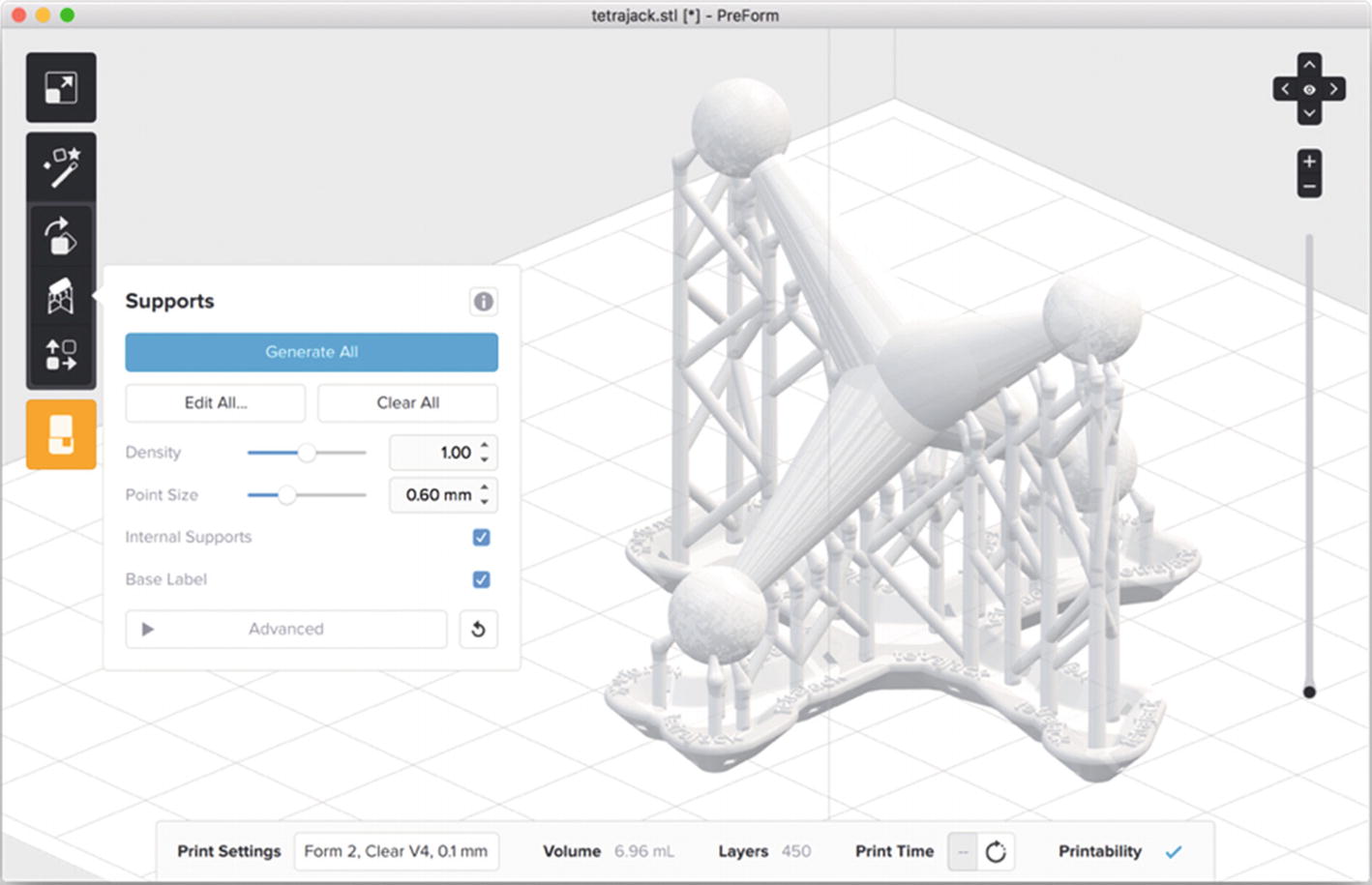
Screen shot from PreForm (courtesy of Formlabs)
When printing in a liquid, you also have to worry about bubbles forming. If any air gets trapped in the print as it forms, that can result in voids in the print since nothing will harden there. Prints have to be designed and oriented carefully to allow a way for air to escape.
For DLP printers that do not have proprietary software, there are a few options, notably Datatree3D’s Creation Workshop (needs a paid license fee, https://datatree3d.com/software/ ). Alternatively, NanoDLP ( www.nanodlp.com/download/ ) runs on a Raspberry Pi and is free to users.
Summary
This chapter reviewed the overall workflow of 3D printing, with a particular focus on the process of slicing a model into layers. It discussed different software packages that are available for the process, and some of the many settings that are available to tweak for the best print. The chapter focused primarily on filament-based 3D printers, with a summary of key difference for resin printers.