Your first step in using a 3D printer will be to create a 3D computer model. You do that by scanning an existing object, downloading a model from the web, or creating a model yourself. In each case, there are a lot of options to choose from. There is more to design than picking a software package, though, and there are design decisions you can make that can simplify the printing process.
This chapter first covers the basic file requirements for a 3D printer. Then it reviews options for scanning and downloading 3D models. Finally, the chapter looks at 3D computer-aided design (CAD) and CAD-related programs that you can use to make a 3D model. By the end of the chapter, you should have a computer model that is ready to go on to the next stage of processing. Models can be made from scratch using a 3D CAD program. Some 3D CAD programs are intended for simple beginner projects, but others are more capable (and complex).
Note
If starting from zero seems daunting, you might consider downloading a pre-existing model from a database. However, models from these databases often have problems or will not print at all. In Chapter 5, we give the workflow for creating a cube measuring 20 mm on a side. We recommend trying out something like that first before getting into a situation where you do not know if problems are being caused by the model, the slicing settings (Chapter 3), or the printer hardware.
3D Model File Formats
The term 3D computer model is used in many different contexts, which can cause confusion when someone wants to print something using a 3D printer. In this book, 3D computer model means a computer file that contains enough information about the surface of an object to allow the object to be printed. In the open source consumer 3D printer world, the most common file format is the STL file. This acronym is sometimes said to stand for STereoLithography and sometimes for Standard Tessellation Language.
STL is something of a lowest-common-denominator file format, consisting essentially of a long list of triangles that collectively cover the surface of the object. This is not a terribly efficient format (particularly in its ASCII version, which is a text file), but it has the virtue of being relatively simple to generate and deal with and therefore has become a de facto standard. STL standards exist for both ASCII and binary file versions.
On some Windows computers, you may get an error when saving or moving around an STL file. On Windows, the STL filename extension is presumed to mean Certificate Trust List, and STL files will show up that way in directory listings. STL files will work with 3D printing programs on Windows machines, but sometimes opening the file or saving them will result in an error message complaining about Certificate Trust Lists.
Tip
The open source program MeshLab (discussed under “Mesh Repair Programs” in Chapter 3) is able to translate many different types of files into STL. It can also fix the problems that sometimes occur during translation or as a result of printing incompatibilities in the original model itself.
CT Scans
We introduce the issues with scanning a model in Chapter 3 and discuss commercial scanners. Here we will add a bit to that for scientific users. A scientist may need detailed, high-resolution information about biological structures. Medical professionals and those with access to computerized tomography (CT) scanners have been using CT scans as a starting point for 3D printing. CT scans can capture internal and complex, concave structures. CT scanners are not consumer items, but if you are a scientist or researcher, you might see whether a local hospital or research center offers scans on a fee-for-service basis. Different CT scanners can handle different densities and sizes of objects.
There are also “micro-CT” scanners with smaller beam sizes. University imaging centers and labs buy these smaller scanners for research projects, but often they’re not used full-time, and the facilities will do a scan as a fee-for-service arrangement. Facilities with micro-CT scanners are not cheap, and thus neither are these scans. But if you are solving a real problem, micro-CT scanning may be a powerful way to get the information you need to create 3D models of structures of interest.
CT scanners usually output a DICOM file. A web search will reveal various free and proprietary tools to convert DICOM files to STL files, depending on the specific application at hand. One readily available conversion package is InVesalius. Do a web search for their download page, because the software is available in various versions and you may want to hunt around for one that is right for you.
Downloading and Modifying Models
Sometimes a model of something that you would like to print already exists. In that case, you may be able to download it from one of a growing number of model databases. Some databases contain fun items and household objects. Some of the existing models in databases are of complex, specialized objects that might be very useful to you professionally.
Models of Everyday Things
Many databases of 3D-printable objects are available online. The Thingiverse ( www.thingiverse.com ), Youmagine ( www.youmagine.com ), Pinshape ( www.pinshape.com ), and Instructables ( www.instructables.com ) websites all feature a wide range of objects, from sci-fi figurines to parts for enhancing 3D printers. These models have been contributed by users and as such vary widely in the quality of their design both for printing and for their intended purposes.
Sometimes model creators will upload both the STL file for printing and the file in the original format of the software that created the model. That means if you happen to be conversant in the original program, you can start with an object and modify it. For example, in Thingiverse, when you click the Download This Thing! button, you get both a list of the available files and the type of license under which each is being made available. Sometimes the developer just wants you to credit them if you use it. Sometimes commercial use is not allowed. If you obtain something from one of these databases, be sure to look carefully at the requirements, particularly if you’re going to modify the object or sell something based on it. See Chapter 3’s notes on Creative Commons licenses.
Specialized Databases
Chimera, from the University of California, San Francisco ( www.cgl.ucsf.edu/chimera/ )
Visual Molecular Dynamics (VMD), from the University of Illinois at Urbana-Champaign (www.ks.uiuc.edu/Research/vmd/)
Both programs have extensive documentation. They are freely available, but have some restrictions on commercial use.
The National Institutes of Health (NIH) in the United States maintains a repository of medicine-related models ( https://3dprint.nih.gov ). The Smithsonian ( https://3d.si.edu ) and other institutions are increasingly putting together “greatest hits” downloadable sets from their collections. Often, though, these files are huge and may have other issues. You will probably want to repair and decimate them — see the section “Repairing a Mesh” in Chapter 3.
Tip
Do not assume that an STL file you download from a site is perfect or that it will work on your printer. It is usually wise to run files through MeshLab (see Tip earlier in this chapter) or a similar program to see if they are watertight and manifold (see Chapter 3) On download sites that allow comments or that have an “I made one!” contribution area, see whether anyone besides the author has made one. If not, that might be a bad sign.
Creating a New Model
If you want to print out something that does not exist anywhere, you will need to use software yourself to develop a new model. Fortunately, many software packages are available that make developing particular types of models as simple as possible. This section helps you think about which CAD software package you may want to learn about, if you do not already use one.
Using a CAD Program
Most CAD programs will either save a file as STL directly or offer an option to “export to” STL. Which CAD program is the right one for the job? This section describes commonly used programs ranging in price from open source and/or free to quite expensive. The programs also vary in the steepness of their learning curves. In general, the more powerful the program, the longer it takes to be reasonably proficient in its use.
Some software packages are geared toward creating models meant to be viewed on a computer or theater screen (called 3D rendering). A “3D” movie normally does not contain the parts of the model that are not on the screen at that moment. Various tricks exploit the way your eyes perceive 3D and fool you into thinking you are seeing a 3D image when really all you are seeing is two offset versions of a 2D image.
If you are at a 3D movie looking at a 3D stereo image of the north side of a tree, that side was generated in a computer. The south side of the tree, the underside of the trunk, and some of the top, east, and west sides are not needed for the movie viewer to see the tree in 3D. However, all of that is needed for printing an object. Be sure the software you are looking into can export an STL file or a format that can be converted into STL.
Some programs have the user write computer-code–like instructions, whereas others require a lot of mouse use and more of an artistic bent. This is a quick overview of some of the available options; for the most part, the open source programs offer extensive documentation available for free download. The proprietary software programs typically offer training or have help available.
Options for Getting Started Quickly
If you want to go from “zero to plastic” as soon as possible, you might try Tinkercad ( www.tinkercad.com ) and OpenSCAD ( www.openscad.org ), both of which are free. Tinkercad requires registration; OpenSCAD is open source. Both have example files available that you can play with and use as guidelines for your own first project.
Tinkercad: Drag and Drop
If you want to use something simple that requires no programming knowledge at all, you will like Tinkercad. Tinkercad is a member of Autodesk’s suite of 3D printing productivity tools. The program is free as of this writing, although it requires the user to register. Tinkercad is a purely drag-and-drop program that supplies a lot of simple shapes such as rectangular solids, spheres, cylinders, three-dimensional letters of the alphabet, numbers, and so on. Printable objects are created by assembling them out of these standard virtual pieces.
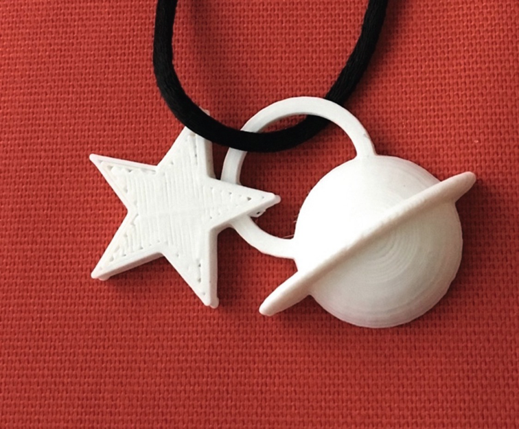
Saturn and star pendant
Tinkercad has extensive tutorials that are arranged into bite-sized brief walkthroughs of the key features, and there are a lot of examples that others have designed and put out there for you to play with and build upon. The classic project to try first on a 3D printer is a small keychain fob decorated with 3D initials or a few hearts. Most people can do a project of that scale in an hour or so starting from zero with Tinkercad. In Chapter 5, we suggest just printing a cube from Tinkercad as an end-to-end plastic “hello world.”
To get started in Tinkercad, follow the process at the Tinkercad home page, www.tinkercad.com . Autodesk also has special accounts for teachers to register their students; click the Learn tab for details. First, you will need to create an account (with Autodesk) to use the program. There are good tutorials on the site that appear by default when you go in for the first time.
When you feel comfortable, you can close the tutorial and click “Create new design” to open a new open build plate. You can drag the preexisting shapes onto the build plate, select two or more of them, and use the group icon to merge them into more complex building blocks. You can make any shape a hole (negative space) by selecting the shape you want to use as a hole and then clicking the “hole” graphic. By adding and subtracting shapes, you can build up fairly complex models.
Tinkercad also has features that are new as of this writing – scribble and a coding capability. We describe those in some detail in Chapter 11.
Save your model by clicking the Export button and selecting the option to download for 3D printing. Laser cutting is an option too, for models that can be made as a flat cutout.
You should now have an STL file in your downloads folder that you can import into your slicer of choice (see Chapter 3) and ultimately print. Tinkercad makes up weird, pseudo-Swedish names for models. You can make them something more memorable by clicking the name it made up and typing in what you would like to call it. Alternatively, you can take one of the public Tinkercad models and alter it a bit, if the model creator allows that, and then save it to STL. Remember to start small and simple—see the “3D Printing Design Rules” section at the end of this chapter about what makes a model “simple.”
Tinkercad also has the ability to model basic circuits and create enclosures for some electronics components in your 3D print. See www.tinkercad.com/circuits for details.
Note
There are a variety of other low-cost, school-oriented CAD programs, and more pop up all the time. Morphi ( www.morphiapp.com ) has a small cost per seat, but does not require a live wifi connection (which Tinkercad does). People sometimes try to use Inkscape ( https://inkscape.org ) for 3D printing, but it is not designed for it, and you will need to export your drawing to another program to extrude it into the third dimension. The result after all that will be better suited for a laser cutter.
OpenSCAD: A CAD Programming Environment
OpenSCAD follows the opposite philosophy from Tinkercad in that it is not drag and drop at all, except for adjusting how you view the model you have developed. OpenSCAD uses a programming language very similar to C to define geometrical shapes, translations, rotations, and so on.
OpenSCAD simple demonstration
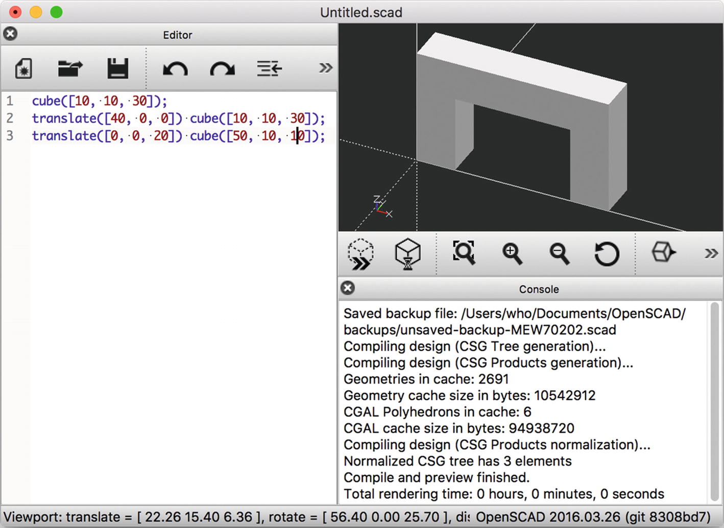
To try out a simple model in OpenSCAD, first either click File ➤ New to start a new model or pick an example from the Example submenu. You can also type in the little example shown in Figure 6-2—the three lines shown are all you need for the model shown. As with any program, saving frequently is a good idea, which you do from the File menu. This will save the program in OpenSCAD format, not STL.
If you want to see what your model will look like, select Design ➤ Preview. This creates a quick visualization of your model without taking the time to calculate all the geometry.
Click and drag with your mouse in the preview pane to roll your model around and see it from different angles. This is also useful to give you a better idea of what the shape actually looks like in 3D.
If you like the looks of what you see in the 3D preview, you’ll want to render the model and create an STL. Go back to Design ➤ Render. This may take longer than the preview step (especially if your model is very complex or uses certain computationally-intensive elements), which is why the preview is available.
When rendering has finished, the preview pane will update. If you had used colors or certain other features, you may notice that they disappear, because they are not supported by STL and thus are only usable for previewing. Roll your model around in the 3D view again and make sure it still looks like you expect. If it does, go to File ➤ Export and then choose STL as the file format.
You can then take the STL file and run it through a slicing program (see Chapter 3) and you will be ready to print. OpenSCAD is particularly suited to modeling objects that can be built up out of geometric shapes. Complex objects are possible by starting with these basic shapes and rotating them. You can make impressive geometries with a little programming experience and the OpenSCAD manual. We have two books of 3D printed science and math models, all of which were created in OpenSCAD (3D Printed Science Models (Apress, 2016) and 3D Printed Science Models Volume 2 (Apress, 2017). Figure 6-3 shows a botanical model from the “Plants and their Ecosystems” chapter of the 2016 book.
Tip
It is helpful if you create an STL and export it in the orientation you expect to print it in. Consider minimizing support. One special case is thin objects with a lot of surface detail, like the models in Figure 6-3. In that case, you may want to print the objects standing on end, as these were printed. As long as the overhangs are manageable, this should work well.

Botanical model (agave plant) from 3D Printed Science Models (Apress, 2016)
Programs for Specific Applications
Tinkercad and OpenSCAD are great for beginners. If you are using your printer mostly as a hobbyist, in a classroom, or to make fun objects around the house, you can probably be happy for a long time with these programs. However, if you need to create professional-level sculptural models, or if you need dimensioned drawings, then these programs probably are not enough. Many, many design programs can either produce an STL file or a file that can be translated into STL. Most of these programs deserve (and in some cases have) their own book-length tutorials.
Generally speaking, you need to consider a few key attributes when selecting a design program. First, think about your own strengths: are you good at programming, or are you better at drawing with a mouse? Do you have decent hand-eye coordination and drawing skills? How much time do you have to devote to becoming proficient, and how much design are you really going to do? A program with a short learning curve but limited capability may be okay if you are only going to make a few complicated objects, but learning a more-capable program may be worth it if those features will vastly enhance your productivity.
Some software only runs on either Mac or Windows, not both. If you only have access to one or the other operating system, that may force a choice.
Next, consider budget. Free and open source software varies in quality; documentation can be uneven or incomplete for open source software. However, it is free. For pricey software, research whether demonstration versions of the software are available, and if so, try before you buy. If you are a student, check with your school to see whether any discounts are available to you.
With all that said, programs to create models for 3D printing need to serve various constituencies. Engineers, architects, industrial designers, mathematicians, and similar professionals need drawings with each part’s dimensions shown and great precision. Often, they will need to integrate 3D printed parts with traditionally manufactured ones and thus will need both the ability to create a file for printing and a traditionally dimensioned, human-readable drawing. Artists may want good drawing tools that allow them to sketch freely but not require as much precision. Different tools have evolved for these respective communities, as we will see next.
Engineering and Architecture Programs
Engineers, industrial designers, and architects use 3D modeling programs oriented toward applications that require precision. A relatively new arrival on the engineering CAD scene is Onshape ( www.onshape.com ). Onshape is cloud based and free for many educational uses. It has a growing suite of plug-ins for modeling and analysis. It runs in a browser, so it runs on Chromebooks, Macs, and Windows and Linux machines, and it also has apps for iOS and Android devices.
Fusion360 ( www.autodesk.com/products/fusion-360 ) is Autodesk’s entry in this category. Autodesk used to have a line of CAD programs called “123D…”. The simpler end of these applications has been rolled into Tinkercad, and the more sophisticated, into Fusion360. Fusion360 has some CAM (computer-aided manufacturing) capability included. It also has (confusingly) a “slicer” function, but it slices models into pieces suitable for laser cutting as interlocking pieces. As of this writing, its CAM abilities were limited to CNC machines, and not 3D printers. The program is free for many educational and personal applications at the moment; see the website for terms and conditions, or to purchase it.
A common (but expensive) engineering tool is Solidworks, from Dassault Systèmes ( www.solidworks.com ). Solidworks is designed to create real engineering projects and as such is a good end-to-end program to go from concept to final dimensioned parts. It does take a while to become proficient in Solidworks, though, and cost can be a barrier once one is beyond the reach of educational discounts. Solidworks is only available for Windows (although there is a free viewer called eDrawings that works on Macs).
Sketchup ( www.sketchup.com ) is a program focused on making it easy to lay out an architectural project, including a large library of many common home fixtures from various manufacturers. Sketchup can be used more broadly, but it focuses mostly on assembling geometrical and precise models, and the resulting models may require format conversion and have problems with 3D printing.
Mathematica ( www.wolfram.com/mathematica/ ) is a programming system that allows users to model complicated mathematical functions. Mathematica creates STL files based on user-generated mathematical models. That means it’s possible to develop sophisticated mathematical models and then visualize them in physical form. This possibility has many implications, particularly for people who teach courses that use Mathematica. A natural spectrum of mathematics visualization options starts with OpenSCAD and moves up to Mathematica.
Visual-Effects and Sculptural Programs
Visual-effects developers, animators, and similar artists develop 3D models in computer programs that are good for complex, curved, organic objects such as characters in animated films. Most of these either can export an STL file directly or employ translation utilities and procedures to take their output and turn it into STL. The commercial program Rhino, for example, exports directly into STL.
Zbrush ( www.zbrush.com ) is another commercial program for artists. It’s a complex but very capable program that allows the user to sculpt in virtual clay. Users often abandon the mouse and draw instead on a graphic tablet with a stylus to create very sophisticated, realistic designs of animated characters and the like.
Blender is an open source visual-effects development program, available from www.blender.org . It is extremely powerful—you can make an entire animated film with it—but has a correspondingly steep learning curve. If you are very fast with a mouse, this may be the program for you, but the program is notorious for “thinking” differently from all other programs. It is, however, free.
Tip
If you are interested in creating 3D models with Blender, you might try to locate a class or, even better, a local Blender community or Meetup group. Lynda.com/LinkedIn Learning has online Blender courses.
Maya ( www.autodesk.com/products/maya ), an animation program, exports OBJ files that some slicing programs, including Cura 3, can read. However, Maya is a mesh-based modeler. That means when you draw something, you are creating a “mesh” that defines surfaces rather than working with geometric solids and letting the software generate their surfaces.
For example, if you model a ball and cut it in half, you are creating a cup-shaped hemispherical surface, facing outward, but it doesn’t have an inward-facing surface, and does not enclose any volume. The software later in the 3D-printing workflow will do unpredictable things with this. You need to use the solidify functions of the modeling software to give your mesh some thickness, or add faces to the open sides to create a half-sphere. Once you are sure your mesh has no holes connecting the inside to the outside, and that the surface does not intersect with itself, you can safely export it as an OBJ file.
Because programs like Maya or Blender are intended only for creating models that will look right when rendered as 2D images, the user has to do some extra work to ensure that the models it produces will be manifold. You will have to make sure that your meshes are all closed and have no unnecessary internal geometry or self-intersections, or your slicing program and printer might both do unpredictable things.
If you want to turn a 2D surface into a printable mesh, you will need to extrude or “solidify” it so that it has a thickness of at least a millimeter or two. Be sure you are working in millimeters first or you might make inch- or centimeter-thick walls!
Tip
As of this writing, Maya comes with a plug-in that generates OBJ files, but the plug-in by default is not enabled. Use Maya’s Plugin Manager to enable the OBJexport plug-in so you can then export Maya’s native format to OBJ files.
Creating Multiple-Extruder Files
A printer with dual extruders allows you to print in two colors or, in some cases, two materials. Exactly how this works depends a lot on the dual extruder machine in question, but this general guide will give you some ideas on how to get started with your machine. You can use a dual extruder machine in a couple of different ways. First, you can use a different color of the same material in each extruder. You can also load one extruder with a dissolvable support material so that you can just wash off support. You may also be able to combine different materials with different properties, or your printer may have the ability to use the second extruder in parallel to make two identical objects. There are now several different types of multi-extruder setups, each with its own capabilities and caveats.
Using One Extruder for Support Material
If you are printing something with significant amounts of support material, you may want to simplify the removal of that support. Dissolvable support is made for this purpose. In this case, no extra steps are necessary prior to sending an STL file to your slicing program (Chapter 3). You will need to tell the slicer which extruder is using the support material.
Water-soluble support filament is usually relatively expensive, and may come in smaller quantities (both for cost reasons and because it can be ruined by leaving it out to absorb moisture from the air). For this reason, it can be advantageous to minimize how much of it you use. Most slicers now have the ability to configure the extruder used for the support interface separately from the rest of the support structures, which allows you to print the bulk of the supports with the cheaper print material and only use the soluble material for the interface between the supports and the part. Depending on the geometry and orientation of your part and of its support structures, this may allow the supports to just fall off, or some breaking of the supports might still be required to remove them, but it makes support removal easier and less likely to mar the surface of your part than using break-away supports.
If your printer has multiple extruders that share a single nozzle, you may find there is no way to use them for materials with different properties, or if you can, that it requires significant purging of the extruder to switch back and forth. Using a support material that is formulated to have similar printing temperatures to your print material will help.
Two-Color or Two-Material Prints
As mentioned, dual-extruder printers allow you to print objects in two colors or materials. It is still a little complicated, though. First, you need to create the STL files for each of the extruders separately, so that you can assign each one to an extruder. In the example here, we will be printing a red heart pendant with a light blue star and exclamation point. This entire object was created in Tinkercad, with the exclamation point, star, and heart all in the same file.
To create a two-color object, we needed to create two separate STL files. To create the first one, we turned the heart/pendant hook into a “hole” in Tinkercad and subtracted it from the merged item to ensure that the two shapes would not overlap. We then saved that much into what we will call STL number 1.
Then, to make the second STL, we undid the merging, turned the heart/pendant back into a regular object, and deleted the star and exclamation point so that we could export just that part as STL number 2. Remember to undo the deletion (or better yet, work with a copy of your original file) so that you don’t lose the ability to edit your file and try again.
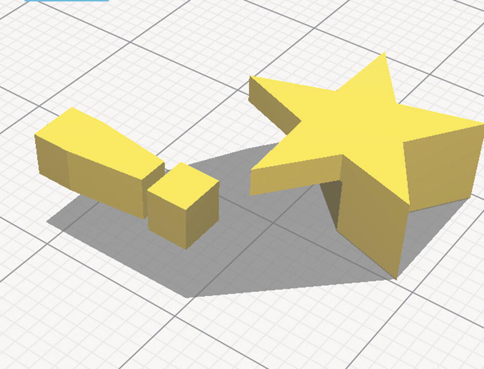
The first of two models to be merged in a dual extruder print
The second model
While making these two files, we were careful not to move anything around during this process so that the STL files would line up properly when we re-merged them.
The following directions assume you have two STL files that were created with a process similar to what we just described for our heart pendant—that is, two STLs created in a way that maintains the same coordinate system across the two files and avoids overlaps. If your printer has multiple nozzles, check your documentation for determining the offset between them and making sure that they are at the correct relative heights. For some printers, you will need to enter the correct offset values in the slicer; others carry this information in the firmware. The offset is the distance between the two extruder heads in the x and y directions.
In a pinch, you could measure from the center of one nozzle to the center of the other nozzle, but this is difficult to do and your manufacturer should have given you either a number or a means of determining the number from a print. Unless your printer has some method of moving the inactive nozzle out of the way, height adjustments will need to be made mechanically—otherwise, the lower extruder could collide with the plastic that came out of the other nozzle. Single-nozzle dual extruder systems do not have any offsets to worry about.
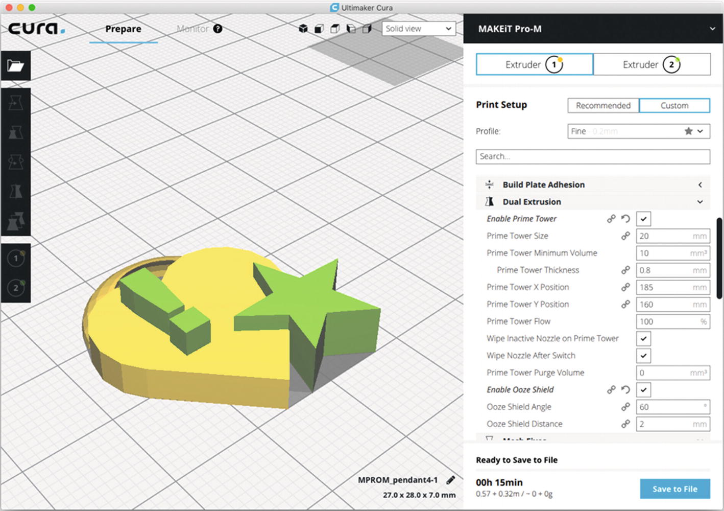
Cura’s Process for a Dual Extruder Print
As we note in Chapter 3, slicing software gets updated a lot. However, the general processes stay about the same. We are going to walk through the process of creating a dual print in Ultimaker Cura 3, since it is so tightly tied to the model generation. For the example here, we used a MAKEiT Pro 3D printer, which automatically handles the extruder offsets in firmware.
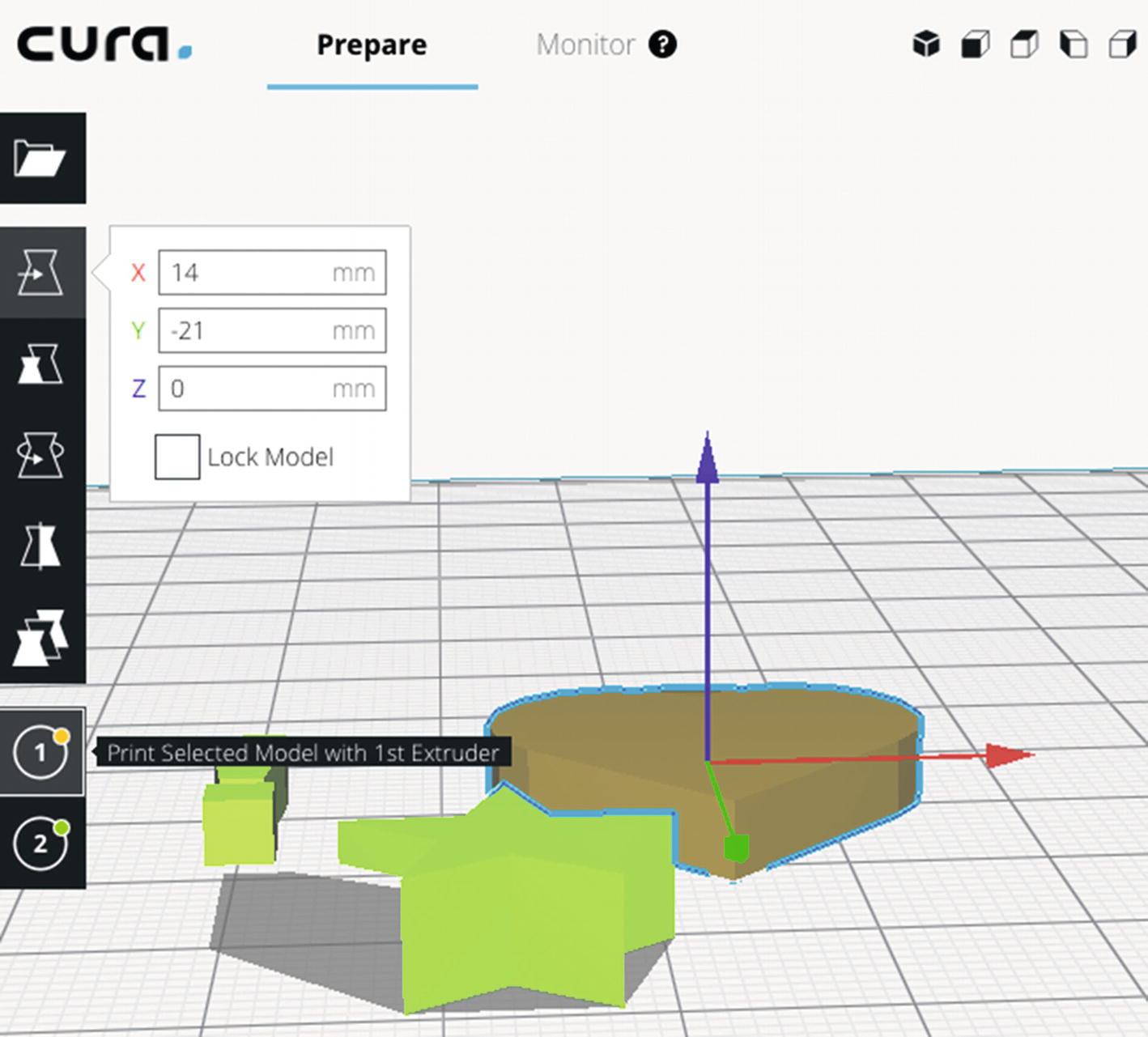
Assigning an extruder to an STL
The merged STLs
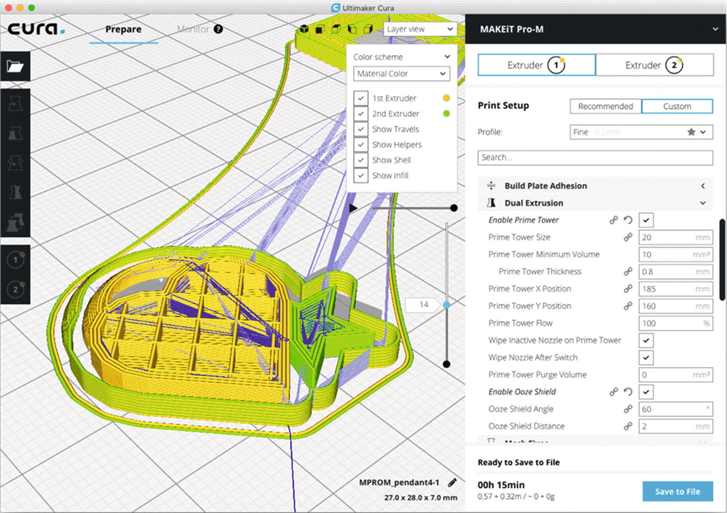
A simulation partway through the print
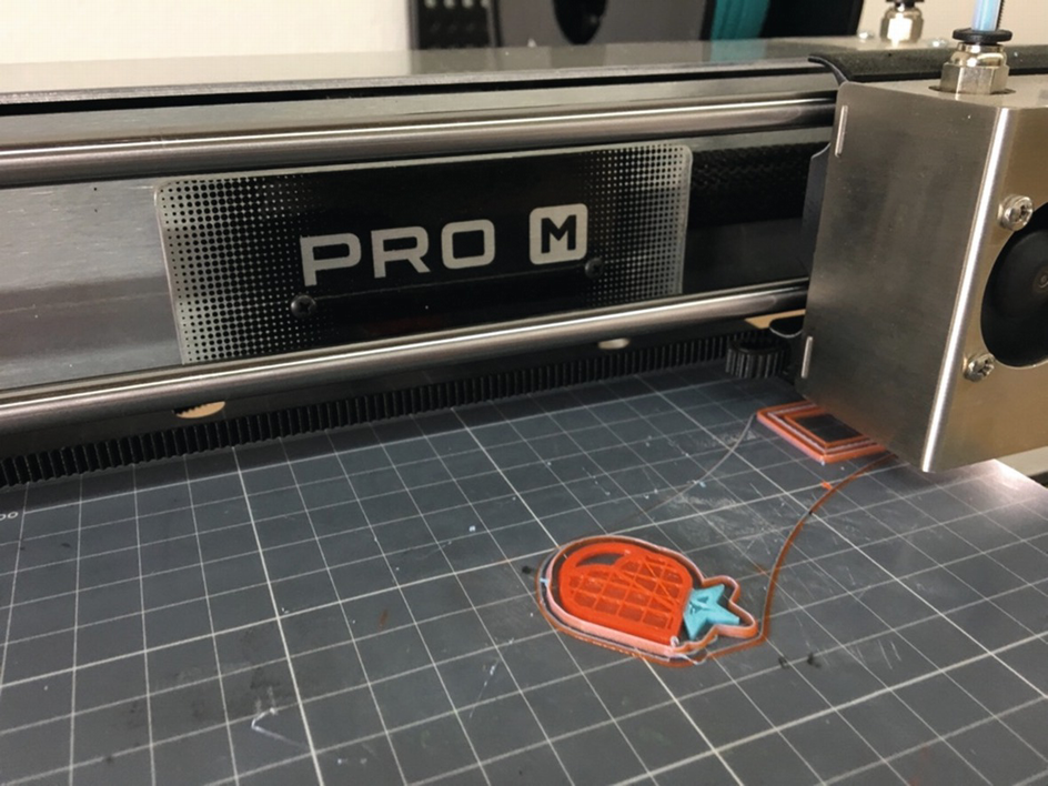
The dual extruder print in process
The completed print on the printer

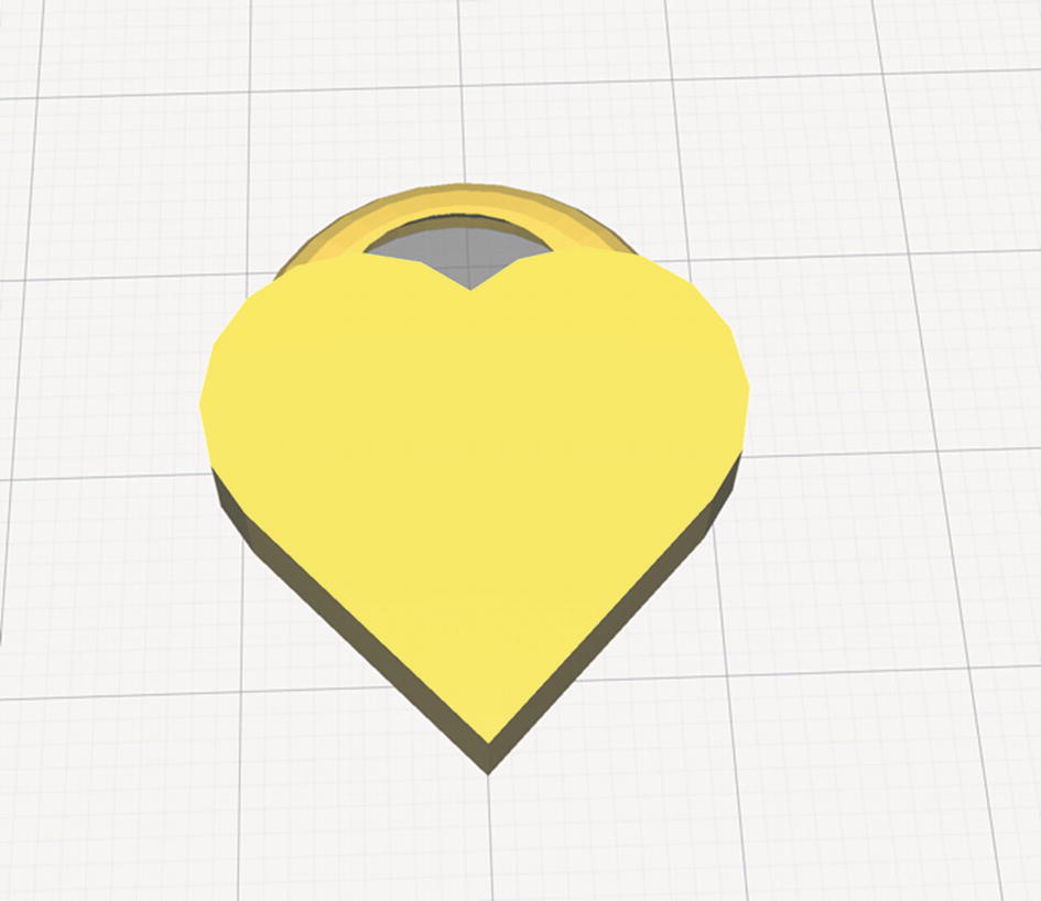
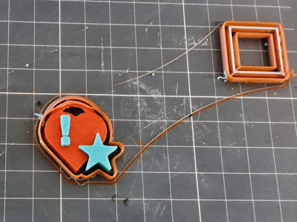
The final print
3D Printing Design Rules
Chapter 3 discusses the software used to create commands for a printer given an STL model. Sometimes minor design changes can make a big difference in how well your print will come out. In 3D printing, the devil is in the details. This section offers a few things to keep in mind when you are designing a 3D print. Then we go into a few philosophical issues about what you can do with a 3D printer that uniquely exploits the value of the technology.
Know your printer’s minimum feature size; for most printers, this will be around 1 mm. Anything smaller will be marginal to print, particularly in the plane of the platform.
Prints can be hollow (as long as the internal overhangs can be bridged), or they can have any infill percentage up to and including solid (100%).
To make a print sturdier, first up the number of perimeters before increasing the percentage infill.
Fine detail should be printed on the side of a print for maximum resolution.
Minimize support by cutting your model into pieces, reorienting it, and so on, while maximizing contact with the build platform. Overhangs of up to about 45 degrees can be handled without support.
If the print is functional and will be stressed, orient it so that loads are in the plane of the platform, not stressing the layer-to-layer bond. (More on this in Chapter 9.)
If you are going to be sanding or otherwise finishing a print in a way that will remove material, or if you will be adding a filler to the surface to smooth it out, allow for that in the print.
10 mm holes are too small for 10 mm parts to fit inside. Leave at least 0.1 mm tolerance as a general rule. You may need more or less depending on your printer, the layer height you are using, the facet size of your model, and how much resistance you want between the two parts, to name a few factors.
Bear in mind the heat, UV light, and chemical sensitivity of your print if it will be used in environments where those things matter. PLA will warp in a hot window in summer, and will deform over time even at room temperature if there is a constant load on it.
Print tall, skinny parts with a cooling tower (Chapter 8).
If a model has a thin part (such as a fin), try to add perimeters until the thin part is solid and work out the thickness so that an even number of perimeters fits, if you have flexibility on sizes. Otherwise infill might be spotty and uneven and distort the surface.
For resin printing, support can be a virtue. Design your model so that the contact area with the platform is minimal, because those layers may be compressed or distorted. To minimize support scarring and peel force, it is often best to print a flat object at 45 degrees in resin.
Resin prints should not have completely enclosed hollow spaces or bowl-shaped areas that could trap resin or air during the print. If they do, the geometry has to have a hole to allow the resin to flow.
Because the prints are more isotropic and can handle smaller features, resolution and strength issues are less of a driver for most resin prints.
Different thermal, chemical, and UV exposure issues affect resins. Because there is now a large range of types of resin, you will need to understand the environmental requirements of your particular resin.
Caution
Most CAD programs and 3D printers use millimeters as a default. Be careful that you do not accidentally save a file in inches, since your print might be interpreted as a teeny version of itself when the slicer opens it and interprets inches as millimeters.
Complexity Is Free: Hardware as a Service
One of the mantras of the 3D-printer community is that complexity is free. Because 3D-printed parts are built up one layer at a time, it really doesn’t matter whether that layer is one unbroken sheet or an intricate design. There are models that would be essentially impossible to machine, but people who know what they are doing can print them on a low-cost consumer printer.
Consumer-level printers have one more strong advantage: the opportunity to iteratively design something, see how it came out, and then change the design if necessary. When that became possible in the 1980s for computing (versus overnight batch jobs), there was a real change to the nature of creating software. We all hope the same thing is about to happen for making physical things!
This phenomenon is starting to be called hardware as a service (an analogy to software as a service), and the business models are still unclear. Resolution and materials are likely to continue improving, and all the pictures in this book will probably look primitive to anyone reading this a few years down the road. Chapter 14 speculates on how 3D-printing businesses may evolve toward short-run manufacturing or mass customization.
Speed vs. Customization
Complexity is not entirely free because the amount of material used (and the time it takes to print) is more proportional to surface area than to volume of the part. Complexity may matter less in 3D printing than in conventional fabrication, but complex prints may take a long time. Consumer 3D printers take a while to print anything out—it’s rare for a print of any size to take less than a few hours, and prints that take a day are routine. If you’re making one of something or a prototype for a mold, such a length of time may be competitive. The other option is a machinist or other professional making a prototype in a way that involves a lot of labor. But if the part is simple or you want a lot of them, a 3D-printed part is probably not the way to go. If you are happily creating injection-molded parts for something now, then 3D-printing that part is definitely not the way to go.
To narrow it down a bit more, consumer 3D printers may not be the best fit for your project if everything you do will require a lot of hand finishing after the fact. You might consider using a service bureau to do one of the more industrial processes. To put it another way, only the right kind of complexity is free.
3D printing has a role for items that are by their nature one-of-a-kind (or a-few-of-a-kind) and that work well with the technology. Time will tell what the best applications are. Our sense is that one key role for 3D printing is that it makes the front of the product-development process faster. People who would have made a computer model and then created a foam-core physical mockup as two separate chores are obviously better off with a 3D printer.
Other promising markets exist in industries that make custom parts for one-of-a-kind applications (or, even better, industries that should operate that way but cannot do so economically at the moment). The biggest market now, though, is a somewhat intangible one: allowing people to make stuff again just because they want to and can.
Summary
In this chapter, you learned about the beginning of the 3D-printing process. The first step is creating or finding a 3D digital model of your object, which requires you to visit a website with objects available for download, 3D-scan something that already exists, or learn one of the many available 3D modeling software packages. The chapter went over the various types of software packages available for the engineer versus the artist to generate a standard (STL) 3D-printing file and some rules of thumb about best design practices for 3D printing.