
Chapter 12
Balancing Resource Utilization
Virtualization with VMware vSphere is, among other things, about getting better utilization of your computing resources within a single physical host. vSphere accomplishes this by letting you run multiple instances of a guest operating system on a single physical host. However, it's also about getting better resource utilization across multiple physical hosts, and that means shifting workloads between hosts to balance the resource utilization. vSphere offers a number of powerful tools for helping administrators balance resource utilization.
In this chapter, you will learn to
- Configure and execute vMotion
- Ensure vMotion compatibility across processor families
- Use Storage vMotion
- Perform Combined vMotion and Storage vMotion
- Configure and manage vSphere Distributed Resource Scheduler
- Configure and manage Storage DRS
Comparing Utilization with Allocation
The fundamental but subtle difference between allocation and utilization can be difficult to understand at times. Allocation is about how a resource is assigned; so in a vSphere environment, allocation is about how CPU cycles, memory, storage I/O, and network bandwidth are distributed to a particular VM or group of VMs. Utilization, on the other hand, is about how resources are used after they are allocated. vSphere provides three mechanisms for allocation: reservations (guaranteed allocations of resources), limits (bounds on the maximum allocation of resources), and shares (prioritized access to resource allocation during periods of resource contention). While these mechanisms are powerful and useful—as you saw in Chapter 11, “Managing Resource Allocation”—they do have their limits (no pun intended). What about situations when a resource is highly utilized on one host and lightly utilized on another host? None of the three mechanisms we've shown you so far will help balance the utilization of resources among ESXi hosts; they will only control the allocation of resources.
VMware vSphere helps balance the intra-cluster utilization of resources in the following four ways:
vMotion vMotion, also generically known as live migration, is used to manually balance compute resource utilization between two ESXi hosts.
Storage vMotion Storage vMotion is the storage equivalent of vMotion, and it is used to manually balance storage utilization between two datastores.
vSphere Distributed Resource Scheduler vSphere Distributed Resource Scheduler (DRS) is used to automatically balance compute resource utilization among two or more ESXi hosts.
Storage DRS Just as Storage vMotion is the storage equivalent of vMotion, Storage DRS is the storage equivalent of DRS, and it is used to automatically balance storage utilization among two or more datastores before and after initial placement of virtual machine files.
As we explain each of these four mechanisms for balancing resource utilization, we'll also introduce or review a few related features of vSphere, such as clusters and VMware Enhanced vMotion Compatibility (EVC).
Let's start with vMotion.
Exploring vMotion
We've defined the vMotion feature as a way to manually balance compute resource utilization between two ESXi hosts. What does that mean, exactly? vMotion can perform a live migration of a VM from one ESXi host to another ESXi host without service interruption. This is a no-downtime operation; network connections are not dropped and applications continue running uninterrupted. In fact, the end users are unaware that the VM has been migrated between physical ESXi hosts. When you use vMotion to migrate a VM from one ESXi host to another, you also migrate the resource allocation—CPU and memory—from one host to another. This makes vMotion an extremely effective tool for manually load-balancing VMs across ESXi hosts and eliminating “hot spots”—heavily utilized ESXi hosts—within your virtualized datacenter.
In addition to manually balancing VM loads among ESXi hosts, vMotion brings other benefits. If an ESXi host needs to be powered off for hardware maintenance or some other function that would take it out of production, you can use vMotion to migrate all active VMs from the host going offline to another host without waiting for a hardware maintenance window. Because vMotion is a live migration—no interruption in service and no downtime—the VMs will remain available to the users who need them.
While it sounds like magic, the basic premise of vMotion is relatively straightforward. vMotion works by copying the contents of VMmemory from one ESXi host to another and then transferring control of the VM's disk files to the target host.
Let's take a closer look. vMotion operates in the following sequence:
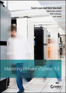
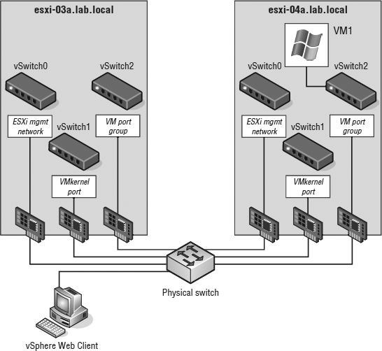
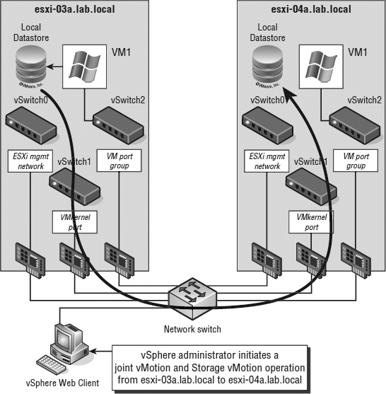
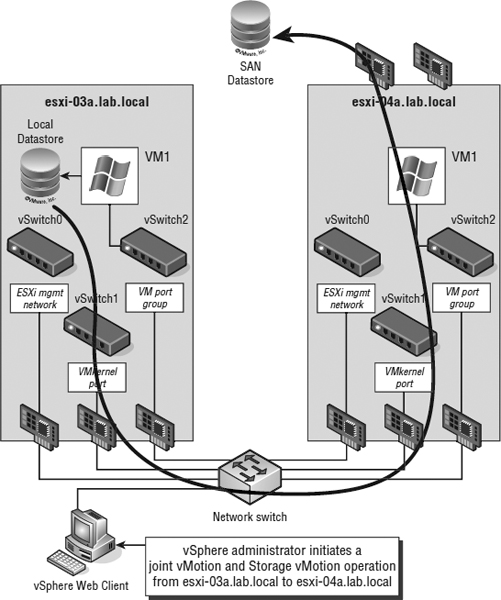
- An administrator initiates a migration of a running VM (VM1) from one ESXi host (esxi-03a) to another (esxi-04a), as shown in Figure 12.1.
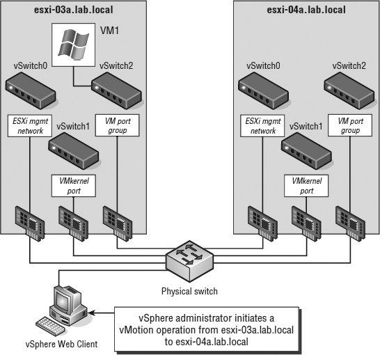
- The source host (esxi-03a) copies the active memory pages VM1 has in host memory to the destination host (esxi-04a) across a VMkernel interface enabled for vMotion. This is called preCopy. Meanwhile, the VM still services clients on the source (esxi-04a). As the memory is copied from the source host to the target, pages in memory can be changed. ESXi handles this by keeping a log of changes that occur in the memory of the VM on the source host after that memory address is copied to the target host. This log is called a memory bitmap. See Figure 12.2. Note that this process occurs iteratively, repeatedly copying over memory contents that have changed.
FIGURE 12.1 Step 1 in a vMotion migration is invoking a migration while the VM is powered on.
FIGURE 12.2 Step 2 in a vMotion migration is starting the memory copy and adding a memory bitmap.
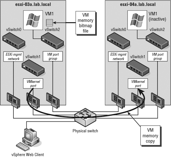
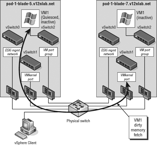
- After the entire contents of RAM for the migrating VM are transferred to the target host (esxi-04a), then VM1 on the source ESXi host (esxi-03a) is quiesced. This means that it is still in memory but is no longer servicing client requests for data. The memory bitmap file is then transferred to the target (esxi-04a). See Figure 12.3.
FIGURE 12.3 Step 3 in a vMotion migration involves quiescing VM1 and transferring the memory bitmap file from the source ESXi host to the destination ESXi host.
THE MEMORY BITMAP
The memory bitmap does not include the contents of the memory address that has changed; it includes only the addresses of that memory—often referred to as the dirty memory.
- The target host (esxi-04a) reads the addresses in the memory bitmap file and requests the contents of those addresses from the source (esxi-03a). See Figure 12.4.
FIGURE 12.4 In step 4 in a vMotion migration, the actual memory listed in the bitmap file is fetched from the source to the destination (dirty memory).
- After the contents of the memory referred to in the memory bitmap file are transferred to the target host, the VM starts on that host. Note that this is not a reboot—the VM's state is in RAM, so the host simply enables it. At this point a Reverse Address Resolution Protocol (RARP) message is sent by the host to register its MAC address against the physical switch port to which the target ESXi host is connected. This process enables the physical switch infrastructure to send network packets to the appropriate ESXi host from the clients that are attached to the VM that just moved.
- After the VM is successfully operating on the target host, the memory the VM was using on the source host is deleted. This memory becomes available to the VMkernel to use as appropriate, as shown in Figure 12.5.
FIGURE 12.5 In step 6 in a vMotion migration, vCenter Server deletes the VM from the source ESXi host.
TRY IT WITH PING
Following the previous procedure carefully, you'll note that the migrating VM does not run for a time on either the source host or the target host. This is typically a very short period. Testing has shown that a continuous ping (ping -t on a Windows OS) of the VM being moved might, on a bad day, result in the loss of one ping packet. Most client-server applications are built to withstand the loss of more than a packet or two before the client is notified of a problem.
Examining vMotion Requirements
The vMotion migration is pretty amazing, and when users see it work for the first time in a live environment, they are extremely impressed. However, detailed planning is necessary for this procedure to function properly. While vMotion is only available through vCenter Server, the hosts involved in the vMotion process have to meet certain requirements along with the VMs being migrated.
Each of the ESXi hosts involved in vMotion must meet the following requirements:
- Shared storage for the VM files (a VMFS or NFS datastore) that is accessible by both the source and target ESXi host.
- A Gigabit Ethernet or faster network interface card (NIC) with a VMkernel port defined and enabled for vMotion on each ESXi host.
VMOTION WITHOUT SHARED STORAGE
As you can see in the section “Examining vMotion Requirements,” we state that vMotion requires shared storage. vSphere 5.1 introduced the ability to also have “shared nothing” vMotion. This new feature uses both vMotion in conjunction with Storage vMotion, and you will find details later in this chapter in the section “Combining vMotion with Storage vMotion.”
This VMkernel port can be on a vSphere Standard Switch, on a vSphere Distributed Switch, or on a third-party distributed virtual switch like the Cisco Nexus 1000V, but it must be enabled for vMotion. The Gigabit Ethernet or faster NIC should be dedicated to vMotion traffic, although you can share this NIC with other traffic types if necessary. In Chapter 5, “Creating and Configuring Virtual Networks,” we provided the steps for creating a VMkernel port on a vSwitch. We included instructions for creating a VMkernel port on either a vSphere Standard Switch or a vSphere Distributed Switch. We'll review the steps for creating a VMkernel port on a vSphere Distributed Switch again just for convenience.
Perform the following steps to create a VMkernel port on an existing vSphere Distributed Switch:
- Launch the Web Client if it is not already running, and connect to an instance of vCenter Server.
- Navigate to the Hosts And Clusters view.
- From the inventory list on the left, select an ESXi host that is already participating in the vSphere Distributed Switch.
- Select the Manage tab from the contents pane on the right.
- Click Networking to display the host's networking configuration.
- Click the Virtual Adapters link.
- In the Virtual Adapters pane, click the link to add a new virtual adapter.
- Select VMkernel Network Adapter and click Next.
- Browse to the correct port group, and click Next.
- Enable the vMotion traffic service and click Next.
- Specify an IP address and network mask for this VMkernel interface.
- Review the pending changes to the distributed switch.
If everything is correct, click Finish to complete adding the VMkernel interface. Otherwise, use the Back button to change the settings accordingly.
VMOTION NETWORK SECURITY
Whenever we design VMware networks, we always ensure that the vMotion network is separated from all other traffic and, where possible, on a non-routed subnet. The reason behind this design decision is that vMotion traffic is not encrypted. That's right; when a VM's memory is copied between ESXi hosts, the traffic is sent in cleartext. This might not be a concern for a lab or even a development environment, but it certainly needs to be considered within a production or multitenant environment. Let's look at a hypothetical situation involving a large bank.
ABank-ESXi-42a is an ESXi host with a VM running an SQL database. This database holds customers' personal details, including credit card numbers. The VM is secured behind multiple firewalls and is far away from the Internet. Obviously, because of the sensitive nature of the data on this server, it can be accessed by only a select number of senior administration staff to perform tasks and maintenance. Because of these precautions, the bank considers this server to be “secure.”
The more junior administration staff have access to the same management network but are specifically denied access to the more sensitive servers, such as this SQL database. One of the junior network admins decides he wants access to the credit card information. He chooses to sniff the network traffic on the management network to see if there's anything interesting going on. In most circumstances, management traffic, such as the vSphere Web Client, is encrypted so the junior admin would get only garbled data.
Unfortunately ABank-ESXi-42a needs to be put into maintenance and the vMotion network is on the same subnet as the management traffic. The vMotion for the SQL VM is initiated and the database that resides in memory is sent in cleartext across the management network for the junior network admin to see.
All the bank needed to do was segment the vMotion network onto an isolated VLAN or subnet that only the vMotion VMkernel ports could access and this situation could have been avoided.
In addition to the configuration requirements just outlined (shared storage and a vMotion-enabled VMkernel port), a successful vMotion migration between two ESXi hosts relies on meeting all of the following conditions:
- Both the source and destination hosts must be configured with identical virtual switches that are correctly configured, vMotion-enabled VMkernel ports. If you are using vSphere Distributed Switches, both hosts must be participating in the same vSphere Distributed Switch.
- All port groups to which the VM being migrated is attached must exist on both of the ESXi hosts. Port group naming is case sensitive, so create identical port groups on each host, and make sure they plug into the same physical subnets or VLANs. A virtual switch named Production is not the same as a virtual switch named PRODUCTION. Remember that to prevent downtime, the VM is not going to change its network address as it is moved. The VM will retain its MAC address and IP address so clients connected to it don't have to resolve any new information to reconnect.
- Processors in both hosts must be compatible. When a VM is transferred between hosts, the VM has already detected the type of processor it is running on when it booted. Because the VM is not rebooted during a vMotion, the guest assumes the CPU instruction set on the target host is the same as on the source host. You can get away with slightly dissimilar processors, but in general the processors in two hosts that perform vMotion must meet the following requirements:
- CPUs must be from the same vendor (Intel or AMD).
- CPUs must be from the same CPU family (Xeon 55xx, Xeon 56xx, or Opteron).
- CPUs must support the same features, such as the presence of SSE2, SSE3, and SSE4 and NX or XD (see the sidebar “Processor Instruction”).
- For 64-bit VMs, CPUs must have virtualization technology enabled (Intel VT or AMD-v).
We'll talk more about processor compatibility in the section “Ensuring vMotion Compatibility.”
PROCESSOR INSTRUCTION
Streaming SIMD Extensions 2 (SSE2) was an enhancement to the original Multimedia Extension (MMX) instruction set found in the PIII processor. The enhancement targeted the floating-point calculation capabilities of the processor by providing 144 new instructions. SSE3 instruction sets are an enhancement to the SSE2 standard targeting multimedia and graphics applications. SSE4 extensions target both the graphics and the application server.
AMD's Execute Disable (XD) and Intel's NoExecute (NX) are features of processors that mark memory pages as data only, which prevents a virus from running executable code at that address. The operating system needs to be written to take advantage of this feature, and in general, versions of Windows starting with Windows 2003 SP1 and Windows XP SP2 support this CPU feature.
The latest processors from Intel and AMD have specialized support for virtualization. The AMD-V and Intel Virtualization Technology (VT) must be enabled in the BIOS in order to create 64-bit VMs.
In addition to the vMotion requirements for the hosts involved, the VM must meet the following requirements to be migrated:
- The VM must not be connected to any device physically available to only one ESXi host. This includes disk storage, CD/DVD drives, floppy drives, serial ports, and parallel ports. If the VM to be migrated has one of these mappings, simply deselect the Connected check box beside the offending device. For example, you won't be able to migrate a VM with a CD/DVD drive connected; to disconnect the drive and allow vMotion, deselect the Connected box.
- The VM must not be connected to an internal-only virtual switch.
- The VM must not have its CPU affinity set to a specific CPU.
- The VM must have all disk, configuration, log, and nonvolatile random access memory (NVRAM) files stored on a VMFS or NFS datastore accessible from both the source and the destination ESXi hosts.
If you start a vMotion migration and vCenter Server finds a violation of the vMotion compatibility rules, you will see an error message. In some cases, a warning, not an error, will be issued. In the case of a warning, the vMotion migration will still succeed. For instance, if you have cleared the check box on the host-attached floppy drive, vCenter Server will tell you there is a mapping to a host-only device that is not active. You'll see a prompt asking whether the migration should take place anyway.
VMware states that you need a Gigabit Ethernet NIC for vMotion; however, it does not have to be dedicated to vMotion. When you're designing the ESXi host, dedicate a NIC to vMotion if possible. You thus reduce the contention on the vMotion network, and the vMotion process can happen in a fast and efficient manner.
GIGABIT REQUIREMENT FOR VMOTION
Although the requirements for a vMotion network state the need for 1 Gbps, technically 600 Mbps is the bare minimum. Keep this in mind when using vMotion over long distances because this may be a more achievable requirement.
Now that we've reviewed all the various prerequisites, both for ESXi hosts and VMs, let's actually perform a vMotion migration.
Performing a vMotion Migration
After you've verified the ESXi host requirements as well as the VM requirements, you are ready to perform a vMotion migration.
Perform the following steps to conduct a vMotion migration of a running VM:
- Launch the Web Client if it is not already running, and connect to a vCenter Server instance.
vMotion requires vCenter Server.
- Navigate to either the Hosts And Clusters or VMs And Templates view.
- Select a powered-on VM in your inventory, right-click the VM, and select Migrate.
- Select Change Host, and then click Next.
- If you have any resource pools defined on the target host or target cluster, you'll need to select the target resource pool (or cluster). You can also select a vApp as your target resource pool; we introduced the concept of vApps in Chapter 10, “Using Templates and vApps.”
To select the individual host in a cluster, check Allow Host Selection Within This Cluster.
Most of the time the same resource pool (or cluster) that the VM currently resides in will suffice, and it is selected by default as the target resource pool. Keep in mind that choosing a different resource pool might change that VM's priority access to resources. Refer to Chapter 11 for a more in-depth discussion of how resource allocation is affected by placement into a resource pool. If no resource pool is defined on the target host, then vCenter Server skips this step entirely. Click Next.
- Choose the target host.
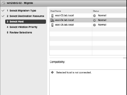
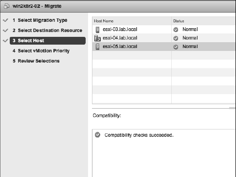
Figure 12.6 shows a target host that produces validation errors; that is, vCenter Server has found errors that would prevent a successful vMotion operation. Figure 12.7 shows a compatible and properly configured target host selected.
FIGURE 12.6 vCenter Server will show you errors found during validation of the selected target host in a vMotion operation.
After you've selected the correct target host, click Next.
FIGURE 12.7 If vCenter Server does not show any validation errors, then the vMotion operation is allowed to proceed.
- Select the priority that the vMotion migration needs to proceed with.
In vSphere 5.5, this setting controls the share of reserved resources allocated for migrations with vMotion. Migrations marked as Reserve CPU For Optimal vMotion Performance receive a reserved share of CPU resources compared to migrations marked as Perform With Available CPU Resources. Migrations will proceed regardless of the resources reserved. This behavior is different than in earlier versions; see the sidebar “Migration Priority in Earlier Versions of vSphere.” Generally, you will select Reserve CPU… (Recommended). Click Next to continue.
MIGRATION PRIORITY IN EARLIER VERSIONS OF VSPHERE
The behavior of the High Priority / Reserved CPU and Standard Priority / Non-Reserved settings for vMotion changed in vSphere 4.1; this behavior carries forward to vSphere 5.5 as described in the text. For vSphere 4, however, the behavior of these options is different. For vSphere 4, high-priority migrations do not proceed if resources are unavailable to be reserved for the migration, whereas standard priority migrations will proceed. However, standard priority migrations might proceed more slowly and might even fail to complete if enough resources are not available.
- Review the settings, and click Finish if all the information is correct.
If there are any errors, use the Back button or the hyperlinks on the left to go back and correct the errors.
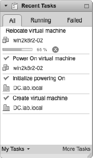
- The VM should start to migrate. Often, the process will pause at about 14 percent in the progress dialog box and then again at 65 percent.
The 14 percent pause occurs while the hosts in question establish communications and gather the information for the pages in memory to be migrated; the 65 percent pause occurs when the source VM is quiesced and the dirty memory pages are fetched from the source host, as shown in Figure 12.8.
FIGURE 12.8 The Recent Tasks pane of the Web Client shows the progress of the vMotion operation.
VMOTION IS NOT A HIGH-AVAILABILITY FEATURE
vMotion is a great feature, but it is not a high-availability feature. Yes you can improve uptime by preventing downtime from planned outages, but vMotion will not provide any protection in the event of an unplanned host failure. For that functionality, you'll need vSphere High Availability (HA) and vSphere Fault Tolerance (FT), two features that are discussed in Chapter 7, “Ensuring High Availability and Business Continuity.”
vMotion is an invaluable tool for virtual administrators. Once you've managed a datacenter with vMotion, you'll wonder how you managed without it.
Over time, though, you could find yourself in a situation where you are without vMotion. As hardware manufacturers such as Intel and AMD introduce new generations of CPUs, some of your ESXi hosts may have a newer generation of CPUs than others. Remember that one of the requirements for vMotion is compatible CPUs. So what happens when you need to refresh some of your hardware and you have to start using a new generation of CPUs? vSphere addresses this potential problem with a feature called VMware Enhanced vMotion Compatibility (EVC).
Ensuring vMotion Compatibility
In the section “Examining vMotion Requirements,” we discussed some of the prerequisites needed to perform a vMotion operation. In particular, I mentioned that vMotion has some fairly strict CPU requirements. Specifically, the CPUs must be from the same vendor, must be in the same family, and must share a common set of CPU instruction sets and features.
In a situation where two physical hosts exist in a cluster and there are CPU differences between the two hosts, vMotion will fail. This is often referred to as a vMotion boundary. Until later versions of ESXi 3.x and appropriate support from Intel and AMD in their processors, there was no fix for this issue—it was something that virtual datacenter administrators and architects simply had to endure.
However, in later versions of VMware Virtual Infrastructure 3.x and continuing into VMware vSphere 4.x and 5.x, VMware supports hardware extensions from Intel and AMD to help mitigate these CPU differences. In fact, vSphere provides two ways to address this issue, either in part or in whole.
Using Per-Virtual-Machine CPU Masking
vCenter Server offers the ability to create custom CPU masks on a per-VM basis. Although this can offer a tremendous amount of flexibility in enabling vMotion compatibility, it's also important to note that, with one exception, this is completely unsupported by VMware.
What is the one exception? On a per-VM basis, you'll find a setting that tells the VM to show or mask the No Execute/Execute Disable (NX/XD) bit in the host CPU, and this specific instance of CPU masking is fully supported by VMware. Masking the NX/XD bit from the VM tells the VM that there's no NX/XD bit present. This is useful if you have two otherwise compatible hosts with an NX/XD bit mismatch. If the VM doesn't know there's an NX or XD bit on one of the hosts, it won't care if the target host has or doesn't have that bit if you migrate that VM using vMotion. The greatest vMotion compatibility is achieved by masking the NX/XD bit. If the NX/XD bit is exposed to the VM, as shown in Figure 12.9, the BIOS setting for NX/XD must match on both the source and destination ESXi hosts.
FIGURE 12.9 The option for masking the NX/XD bit is controlled on a per-VM basis.
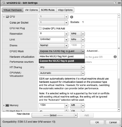
For features other than the NX/XD bit, you would have to delve into custom CPU masks. This is where you will step outside the bounds of VMware support. Looking at the dialog box in Figure 12.9, you'll note the Advanced button. Clicking the Advanced button opens the CPU Identification Mask dialog box, shown in Figure 12.10.
In this dialog box, you can create custom CPU masks to mark off specific bits within the CPU ID value. We won't go into great detail here because all of this is unsupported by VMware, and it's generally not needed provided you run hardware that is on the HCL. However, Scott Lowe has two blog articles that provide additional information:
Fortunately, there's an easier—and fully supported—way of handling this issue, and it's called VMware Enhanced vMotion Compatibility (EVC).
Using VMware Enhanced vMotion Compatibility
Recognizing that potential compatibility issues with vMotion could be a significant problem, VMware worked closely with both Intel and AMD to craft functionality that would address this issue. On the hardware side, Intel and AMD put functions in their CPUs that would allow them to modify the CPU ID value returned by the CPUs. Intel calls this functionality FlexMigration; AMD simply embedded this functionality into its existing AMD-V virtualization extensions.
On the software side, VMware created software features that would take advantage of this hardware functionality to create a common CPU ID baseline for all the servers within a cluster. This functionality, originally introduced in VMware ESX/ESXi 3.5 Update 2, is called VMware Enhanced vMotion Compatibility.
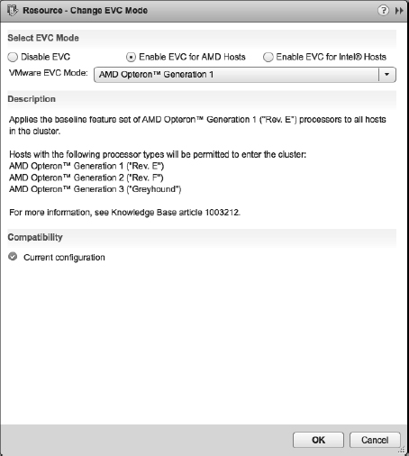
EVC is enabled at the cluster level. Figure 12.11 shows the EVC controls for a cluster.
FIGURE 12.10 The CPU Identification Mask dialog box allows you to create custom CPU masks.
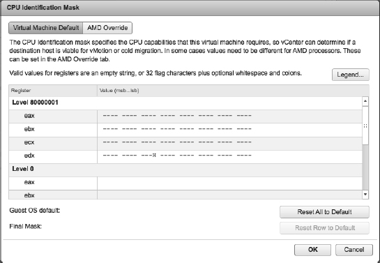
FIGURE 12.11 VMware EVC is enabled and disabled at the cluster level.
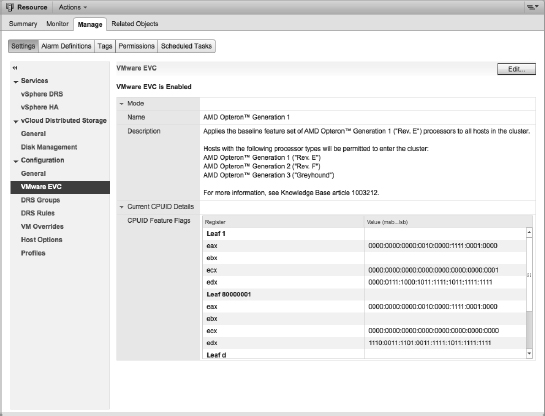
As you can see in Figure 12.11, EVC is enabled on this cluster. This cluster contains servers with AMD Operon processors, so EVC is using an AMD Operon Generation 1 baseline. To change the baseline that EVC is using, follow these steps:
- Click the Change EVC Mode button.
- A dialog box opens that allows you to disable EVC or to change the EVC baseline, as illustrated in Figure 12.12.
FIGURE 12.12 You can enable or disable EVC as well as change the processor baseline EVC uses.
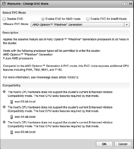
vCenter Server performs some validation checks to ensure that the physical hardware can support the selected EVC mode and processor baseline. If you select a setting that the hardware cannot support, the Change EVC Mode dialog box will reflect the incompatibility. Figure 12.13 shows an incompatible EVC mode selected.
When you enable EVC and set the processor baseline, vCenter Server then calculates the correct CPU masks required and communicates that information to the ESXi hosts. The ESXi hypervisor then works with the underlying Intel or AMD processors to create the correct CPU ID values that would match the correct CPU mask. When vCenter Server validates vMotion compatibility by checking CPU compatibility, the underlying CPUs will return compatible CPU masks and CPU ID values. However, vCenter Server and ESXi cannot set CPU masks for VMs that are currently powered on. (You can verify this by opening the properties of a running VM and going to the CPUID Mask area on the Resources tab. You'll find all the controls there are disabled.)
Consequently, if you attempt to change the EVC mode on a cluster that has powered-on VMs, vCenter Server will prevent you from making the change, as you can see in Figure 12.14. You'll have to power down the VMs in order to change the cluster's EVC mode.
FIGURE 12.13 vCenter Server ensures that the selected EVC mode is compatible with the underlying hardware.

FIGURE 12.14 vCenter Server informs the user which ESXi hosts in the cluster have powered-on or suspended VMs that are preventing the change to the cluster's EVC mode.
When setting the EVC mode for a cluster, keep in mind that some CPU-specific features—such as newer multimedia extensions or encryption instructions—could be disabled when vCenter Server and ESXi disable them via EVC. VMs that rely on these advanced extensions might be affected by EVC, so be sure that your workloads won't be adversely affected before setting the cluster's EVC mode.
EVC is a powerful feature that assures vSphere administrators that vMotion compatibility will be maintained over time, even as hardware generations change. With EVC, you won't have to remember what life's like without vMotion.
Traditional vMotion only helps with balancing CPU and memory load. In the next section we'll discuss a method for manually balancing storage load.
Using Storage vMotion
vMotion and Storage vMotion are like two sides of the same coin. Traditional vMotion migrates a running VM from one physical host to another, moving CPU and memory usage between hosts but leaving the VM's storage unchanged. This allows you to manually balance the CPU and memory load by shifting VMs from host to host. Storage vMotion, however, migrates a running VM's virtual disks from one datastore to another datastore but leaves the VM executing—and therefore using CPU and memory resources—on the same ESXi host. This allows you to manually balance the “load” or utilization of a datastore by shifting a VM's storage from one datastore to another. Like vMotion, Storage vMotion is a live migration; the VM does not incur any outage during the migration of its virtual disks from one datastore to another.
So how does Storage vMotion work? The process is relatively straightforward:
- First, vSphere copies over the nonvolatile files that make up a VM: the configuration file (VMX), VMkernel swap, log files, and snapshots.
- Next, vSphere starts a ghost or shadow VM on the destination datastore. Because this ghost VM does not yet have a virtual disk (that hasn't been copied over yet), it sits idle waiting for its virtual disk.
- Storage vMotion first creates the destination disk. Then a mirror device—a new driver that mirrors I/Os between the source and destination—is inserted into the data path between the VM and the underlying storage.
SVM MIRROR DEVICE INFORMATION IN THE LOGS
If you review the vmkernel log files on an ESXi host during and after a Storage vMotion operation, you will see log entries prefixed with SVM that show the creation of the mirror device and that provide information about the operation of the mirror device.
- With the I/O mirroring driver in place, vSphere makes a single-pass copy of the virtual disk(s) from the source to the destination. As changes are made to the source, the I/O mirror driver ensures that those changes are also reflected at the destination.
- When the virtual disk copy is complete, vSphere quickly suspends and resumes in order to transfer control over to the ghost VM created on the destination datastore earlier. This generally happens so quickly that there is no disruption of service, as with vMotion.
- The files on the source datastore are deleted.
It's important to note that the original files aren't deleted until the migration is confirmed as successful; this allows vSphere to simply fall back to its original location if an error occurs. This helps prevent data loss situations or VM outages because of an error during the Storage vMotion process.
Perform the following steps to migrate a VM's virtual disks using Storage vMotion:
- Launch the Web Client if it is not already running. Storage vMotion is available only when you are working with vCenter Server.
- Navigate to the Hosts And Clusters or VMs And Templates view.
- Right-click the VM whose virtual disks you want to migrate from the inventory tree on the left, and then select Migrate. This is the same dialog box is used to initiate a regular vMotion operation.
- Select Change Datastore and click Next.
- Select a destination datastore or datastore cluster. (You'll learn more about datastore clusters in the section “Introducing and Working with Storage DRS.”)
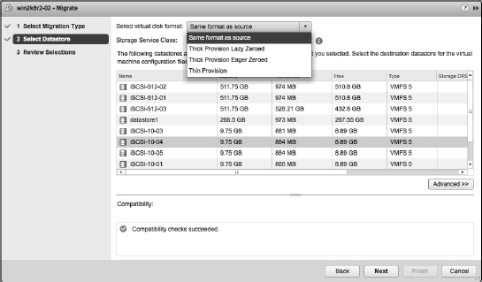
- Select the desired virtual disk format (Same Format As Source, Thick Provision Lazy Zeroed, Thick Provision Eager Zeroed, or Thin Provision).
Storage vMotion lets you change the disk format during the actual disk-migration process, so you can switch from Thick Provision Lazy Zeroed to Thin Provision, for example.
STORAGE VMOTION WITH RAW DEVICE MAPPINGS
Be careful when using Storage vMotion with raw device mappings (RDMs). If you want to migrate only the VMDK mapping file, be sure to select Same Format As Source for the virtual disk format. If you select a different format, virtual mode RDMs will be converted into VMDKs as part of the Storage vMotion operation (physical mode RDMs are not affected). Once an RDM has been converted into a VMDK, it cannot be converted back into an RDM again.
- If you have Storage Service Classes defined in vCenter Server, select the desired class from the Storage Service Class drop-down box.
- If you need to migrate the VM's configuration file and virtual hard disks separately or to separate destinations, click the Advanced button.
Figure 12.15 shows the virtual disk format view of the Storage step of the Migrate Virtual Machine Wizard and how you can choose the destination and disk format for the different VM.
FIGURE 12.15 Use the Migrate Virtual Machine Wizard to change a VM's virtual disk format.
- When you have finished making selections on the Storage screen, click Next to continue with the Migrate Virtual Machine Wizard.
- Review the settings for the Storage vMotion to ensure that everything is correct. If you need to make changes, use the hyperlinks on the left or the Back button.
Once you initiate the Storage vMotion operation, the Web Client will show the progress of the migration in the Recent Tasks pane, as you've seen for other tasks (such as vMotion).
There's a notable difference in how Storage vMotion works with vSphere 5.5 when renaming files. In prior versions of vSphere, the feature was enabled, and then in it was disabled in vSphere 5.1. In vSphere 5.5 the renaming feature is back with extra functionality. We won't go into details on how it used to work, but in vSphere 5.5 when you perform a storage vMotion, vSphere will rename the files that reside on datastores to align to the VM name displayed in the vSphere Web Client. This occurs only if the VM in question has been renamed from the vSphere Web Client. If the VM has not been renamed since it was created or from the last Storage vMotion, this process does not occur. Understand, you don't have the choice to not rename the files. Storage vMotion renames the underlying files to adhere to the VM display name and the file naming convention that VMware specifies if it needs to.
The following files are renamed when part of a Storage vMotion occurs to the following standard <VM name>.<extension>:
- .VMX
- .VMXF
- .NVRAM
- .VMDK
- .VMSN
A few notes and caveats: If a VM has two virtual disks (VMDKs) and you only Storage vMotion one of these disks, only the disk and its associated files would potentially be renamed. If (based on the naming standard) there are two files that would receive the same filename, such as a snapshot disk, a numeric suffix is added to resolve conflicts.
Combining vMotion with Storage vMotion
Introduced with vSphere 5.1, vMotion and Storage vMotion can be combined into a single process to produce what is sometimes called shared nothing vMotion.
Without the need for (usually) expensive shared storage such as a NAS or a SAN, VMware administrators can move their workloads from host to host, regardless of the storage type. Local storage, mixed shared storage, or standard shared storage are all valid options to use when combining vMotion with Storage vMotion.
Generally speaking, the only requirement for the combined vMotion and Storage vMotion is that both hosts must share the same L2 (layer 2) network. You will however need to be using the vSphere Web Client, as this feature is not enabled in the traditional vSphere Client. Depending on how you want this feature to work, however, you may need to add extra requirements, so we'll explain with the following examples.
Example 1
- Two hosts on a single vMotion network.
- Both hosts use local datastores.
The two hosts in Example 1 are connected by a single vMotion network but both hosts only have local datastores, as you can see Figure 12.16. When you're migrating a VM from one to the other, there are two data flows. The first flow initiated is the storage, because this transfer will generally take longer to complete than the memory. After the storage transfer has taken place, the memory copy starts. Although there are two separate data transfers, all data flows over the same vMotion VMkernel network.
FIGURE 12.16 All data flows over the vMotion network when transferring between local datastores.
- Two hosts on a single vMotion network.
- One host uses local datastores.
- One host uses SAN datastores.
A single vMotion network connects the two hosts in Example 2. This time, however, one is connected to a SAN for storage. Within this example, not too much changes with the data flows. The only difference is that the second host pushes the received data to the SAN over its storage network instead of a local datastore. You can see this in detail in Figure 12.17. Both hosts are connected to the shared storage, and that leads us to Example 3.
FIGURE 12.17 Data flows over the vMotion network and then the storage network when transferring between local and non-local datastores.
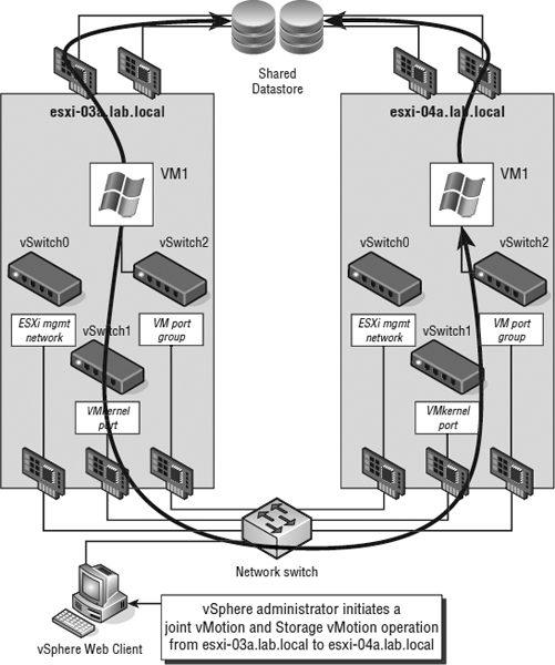
- Two hosts on a single vMotion network.
- Both hosts use a shared Fibre Channel SAN datastore.
The two hosts in Example 3 are more typical of larger enterprise environments. Generally in these situations there is a SAN or NAS connecting all ESXi hosts. In this situation, the data flows are quite different. As usual, the vMotion network carries the memory data flow. The difference in this example involves the shared storage component. Storage vMotion is smart enough to detect when both hosts can see both source and destination datastores. It intelligently uses the storage network instead of the vMotion network to migrate this data even if it's a local datastore at the source! See Figure 12.18.
FIGURE 12.18 Even if the datastores are not the same, Storage vMotion is smart enough to know if both hosts can see the destination datastore. It uses the storage network whenever possible.
Perform the following steps to migrate a VM to a different host and datastore using the combined vMotion and Storage vMotion:
- Launch the Web Client if it is not already running.
- Navigate to the Hosts And Clusters or VMs And Templates view.
- Right-click the VM whose virtual disks you want to migrate from the inventory tree on the left, and then select Migrate. The same dialog box is used to initiate a vMotion and a Storage vMotion operation opens.
- Select Change Both Host And Datastore and click Next.
This option will be grayed out if your cluster hosts are vSphere 5.0 or earlier.
- Select the destination resource and click Next.
- Pick the host that you wish to migrate the VM to and click Next.
- Select a destination datastore or datastore cluster.
- Select the desired virtual disk format (Same Format As Source, Thick Provision Lazy Zeroed, Thick Provision Eager Zeroed, or Thin Provision). Click Next to continue.
- Change the vMotion priority if desired, and click Next to review the changes.
- Finally, review the changes about to be made and click Finish.
When you're combining vMotion and Storage vMotion, the storage is the first migration to take place; the reason behind this is twofold. First, hard disks are both larger and slower than memory; therefore the Storage vMotion will take significantly longer than the vMotion. Second, the rate of change to disk-based storage is usually less than that for memory. If the vMotion operation happened first, the memory bitmap file (discussed earlier in this chapter) would grow much larger while waiting for the Storage vMotion task to complete. That's why it makes a lot more sense for the Storage vMotion operation to happen first.
Like vMotion, Storage vMotion (or a combination of both) is a great approach for manually adjusting the load or utilization of resources, but they are ultimately reactive tools. vSphere DRS and Storage DRS leverage vMotion and Storage vMotion to bring a level of automation to help balance utilization across clusters.
Exploring vSphere Distributed Resource Scheduler
When we introduced you to vMotion and Storage vMotion, we stated that they were a way of manually balancing loads across VMware ESXi hosts. vSphere Distributed Resource Scheduler (DRS) builds on this idea by making the load balancing automatic. The groups are clusters, which we introduced in Chapter 3, “Installing and Configuring vCenter Server,” and discussed again in Chapter 7.
vSphere DRS is a feature of vCenter Server and has the following two main functions:
- To decide which node of a cluster should run a VM when it's powered on, or intelligent placement
- To evaluate the load on the cluster over time and either make recommendations for migrations or use vMotion to automatically move VMs to create a more balanced cluster workload
vSphere DRS runs as a process within vCenter Server, which means that you must have vCenter Server in order to use vSphere DRS. By default, DRS checks every 5 minutes (or 300 seconds) to see if the cluster's workload is balanced. DRS is also invoked by certain actions within the cluster, such as adding or removing an ESXi host or changing the resource settings of a VM. When DRS is invoked, it will calculate the imbalance of the cluster, apply any resource controls (such as reservations, shares, and limits), and, if necessary, generate recommendations for migrations of VMs within the cluster. Depending on the configuration of vSphere DRS, these recommendations could be applied automatically, meaning that VMs will automatically be migrated between hosts by DRS in order to maintain cluster balance (or, put another way, to minimize cluster imbalance).
VSPHERE DISTRIBUTED RESOURCE SCHEDULER ENABLES RESOURCE POOLS
DRS enables the use of resource pools when clustering ESXi hosts. If hosts are part of a HA enabled cluster, DRS must also be enabled to allow Resource Pools to be created.
Fortunately, if you like to retain control, you can set how aggressively DRS will automatically move VMs around the cluster.
If you start by looking at the DRS properties—you can view these properties by right-clicking a DRS-enabled cluster, selecting Settings, clicking the vSphere DRS heading on the left, and then clicking Edit—you will see that there are three selections regarding the automation level of the DRS cluster: Manual, Partially Automated, and Fully Automated. If you click the triangle next to DRS Automation, you will find the slider bar that affects the actions of the Fully Automated setting on the cluster. These settings control the initial placement of a VM and the automatic movement of VMs between hosts. We'll examine the behavior of these automation levels in the next three sections.
Understanding Manual Automation Behavior
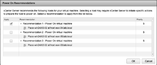
When a DRS cluster is set to Manual, every time you power on a VM, the cluster prompts you to select the ESXi host where that VM should be hosted. The dialog box rates the available hosts according to suitability at that moment: the lower the priority, the better the choice, as shown in Figure 12.19.
FIGURE 12.19 A DRS cluster set to Manual requires you to specify where the VM should be powered on.
The Manual setting also suggests vMotion migrations when DRS detects an imbalance between ESXi hosts in the cluster. This is an averaging process that works over longer periods of time than many of us are used to in the IT field. It is unusual to see DRS make any recommendations unless an imbalance has existed for longer than 5 minutes. You find the recommended list of migrations by selecting the cluster in the inventory and then selecting the DRS tab.
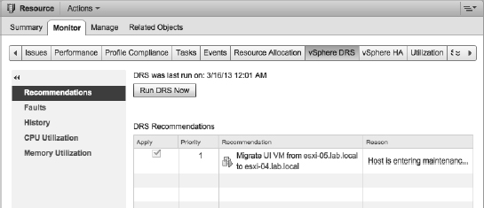
From the Monitor ![]() DRS tab, the Run DRS Now button allows you to agree with any pending DRS recommendations and initiate a migration. vMotion handles the migration automatically. Figure 12.20 shows some pending recommendations displayed on the DRS recommendations section of a cluster that is set for Manual DRS automation.
DRS tab, the Run DRS Now button allows you to agree with any pending DRS recommendations and initiate a migration. vMotion handles the migration automatically. Figure 12.20 shows some pending recommendations displayed on the DRS recommendations section of a cluster that is set for Manual DRS automation.
FIGURE 12.20 vMotion operations must be approved by an administrator when DRS is set for Manual automation.
Reviewing Partially Automated Behavior
If you select the Partially Automated setting in the DRS Automation settings, DRS will make an automatic decision about which host a VM should run on when it is initially powered on (without prompting the user who is performing the power-on task) but will still prompt for all migrations on the DRS tab. Thus, initial placement is automated, but migrations are still manual.
Examining Fully Automated Behavior
The third setting for DRS is Fully Automated. This setting makes decisions for initial placement without prompting and also makes automatic vMotion decisions based on the selected automation level (the slider bar).
There are five positions for the slider bar for the Fully Automated setting of the DRS cluster. The values of the slider bar range from Conservative to Aggressive. Conservative automatically applies recommendations ranked as priority 1 recommendations. Any other migrations are listed on the DRS tab and require administrator approval. If you move the slider bar from the most conservative setting to the next stop to the right, then all priority 1 and priority 2 recommendations are automatically applied; recommendations higher than priority 2 will wait for administrator approval. With the slider all the way over to the Aggressive setting, any imbalance in the cluster that causes a recommendation is automatically approved (even priority 5 recommendations). Be aware that this can cause additional stress in your ESXi host environment because even a slight imbalance will trigger a migration.
Calculations for migrations can change regularly. Assume that during a period of high activity DRS makes a priority 3 recommendation and the automation level is set so priority 3 recommendations need manual approval, but the recommendation is not noticed (or an administrator is not even in the office). An hour later, the VMs that caused the recommendation in the first place have settled down and are now operating normally. At this point, the DRS tab no longer reflects the recommendation. The recommendation has since been withdrawn. If the migration were still listed, an administrator might approve it and cause an imbalance where one did not exist.
In many cases, priority 1 recommendations have little to do with load on the cluster. Instead, priority 1 recommendations are generally the result of one of two conditions. The first condition that causes a priority 1 recommendation is when you put a host into maintenance mode, as shown in Figure 12.21.
FIGURE 12.21 An ESXi host put into maintenance mode cannot power on new VMs or be a target for vMotion.
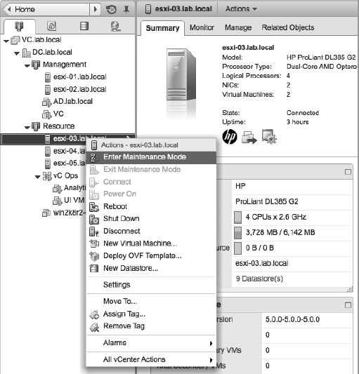
Maintenance mode is a host setting that prevents the ESXi host from performing any VM-related functions. VMs running on a host being put into maintenance mode must be shut down or moved to another host before the host will actually enter maintenance mode. That is, an ESXi host in a DRS-enabled cluster will automatically generate priority 1 recommendations to migrate all VMs to other hosts within the cluster. Figure 12.20 shows priority 1 recommendations generated as the result of an ESXi host being placed into maintenance mode.
The second condition that could cause a priority 1 recommendation is when DRS affinity rules come into play. This leads us to a discussion of DRS affinity rules.
A QUICK REVIEW OF DISTRIBUTED RESOURCE SCHEDULER CLUSTER PERFORMANCE
Monitoring the detailed performance of a cluster is an important task for any virtual infrastructure administrator, particularly monitoring the CPU and memory activity of the whole cluster as well as the respective resource utilization of the VMs within the cluster. The Summary tab of the details pane for a cluster object includes information on cluster configuration as well as statistics for the current load distribution. Additionally, the View Resource Distribution Chart shows the current resource distribution of the ESXi hosts in the cluster. While resource allocation and distribution isn't necessarily a direct indicator of performance, it can be a helpful metric nevertheless.
Working with Distributed Resource Scheduler Rules
To further allow an administrator to customize the behavior of vSphere DRS for their specific environment, vSphere lets you create DRS rules. vSphere DRS supports three types of DRS rules:
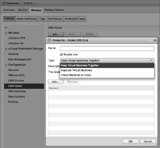
- VM affinity rules, referred to as Keep Virtual Machines Together in the Web Client
- VM anti-affinity rules, referred to as Separate Virtual Machines in the Web Client
- Host affinity rules, referred to as Virtual Machines To Hosts in the Web Client
Figure 12.22 shows these three types of rules in the dialog box for creating new DRS rules.
FIGURE 12.22 DRS supports VM affinity, VM anti-affinity, and host affinity rules.
Recall from the previous section that DRS rules are the second of two conditions that will trigger a priority 1 recommendation (the other is maintenance mode). When DRS detects that VMs will violate DRS rules, it generates a priority 1 recommendation to migrate one or more VMs in order to satisfy the constraint expressed in the DRS rule.
vSphere's DRS rule functionality gives vSphere administrators the power to model the complex relationships that often exist in today's datacenters. Let's take a closer look at each of these three types of DRS rules.
CREATING VM AFFINITY RULES
Affinity rules keep VMs together on the same host. Consider a multitier application where you have a web application server and a backend database server that frequently communicate with each other and you'd like that communication to take advantage of the high-speed bus within a single server rather than going across the network. In that case, you could define an affinity rule (Keep Virtual Machines Together) that would ensure that these two VMs stay together in the cluster.
Perform the following steps to create a DRS affinity rule:
- Launch the Web Client if it is not already running, and connect to a vCenter Server instance.
DRS and DRS rules cannot be managed when connected to a specific ESXi host; you must connect to a vCenter Server instance.
- Navigate to the Hosts And Clusters view.
- Right-click the DRS cluster where the rules need to exist, and select the Settings option.
- Click the DRS Rules option.
- Click the Add button near the top of the pane.
- Type a name for the rule, and select Keep Virtual Machines Together for the type of rule to create.
- Click the Add button to include the necessary VMs in the rule. Simply select the check box for the VMs you want to include in the DRS rule.
- Click OK.
- Review the new rule configuration to ensure that it is correct.
- Click OK.
VM affinity rules let you specify VMs that should always stay together, but what about VMs that should always stay separate? DRS offers that functionality with VM anti-affinity rules.
CREATING VM ANTI-AFFINITY RULES
Consider an environment with two mail server VMs. In all likelihood, administrators would not want both mail servers to reside on the same ESXi host. Instead, the administrators would want the mail servers split onto two different ESXi hosts in the cluster, so that the failure of one host would affect only one of the two mail servers. In this sort of situation, a VM anti-affinity rule is the right tool to use.
Perform the following steps to create a DRS anti-affinity rule:
- Launch the Web Client if it is not already running, and connect to a vCenter Server instance. Recall that DRS and DRS rules are available only with vCenter Server.
- Navigate to the Hosts And Clusters view.
- Right-click the DRS cluster where the rules need to exist, and select the Settings option.
- Click the DRS Rules option.
- Click the Add button near the top of the pane.
- Type a name for the rule, and select Separate Virtual Machines as the type of rule to create.
- Click the Add button to include the necessary VMs in the rule. Simply select the check box for the VMs you want to include in the DRS rule.
- Click OK.
- Review the new rule configuration to ensure that it is correct.
- Click OK.
With both VM affinity and VM anti-affinity rules, it is possible to create fallible rules, such as building a Separate Virtual Machines rule that has three VMs in it on a DRS cluster that has only two hosts. In this situation, vCenter Server will generate report warnings because DRS cannot satisfy the requirements of the rule.
So far you've seen how to instruct DRS to keep VMs together or to keep VMs separate, but what about situations where you want to constrain VMs to a group of hosts within a cluster? This is where host affinity rules come into play.
HOST AFFINITY RULES FIRST APPEARED IN VSPHERE 4.1
VMware introduced host affinity rules in vSphere 4.1. Host affinity rules were not available in earlier versions.
WORKING WITH HOST AFFINITY RULES
In addition to VM affinity and VM anti-affinity rules, vSphere DRS supports a third type of DRS rule: the host affinity rule. Host affinity rules govern the relationships between VMs and the ESXi hosts in a cluster, letting administrators control which hosts in a cluster can run which VMs. When combined with VM affinity and VM anti-affinity rules, administrators can create very complex rule sets to model the relationships between applications and workloads in their datacenter.
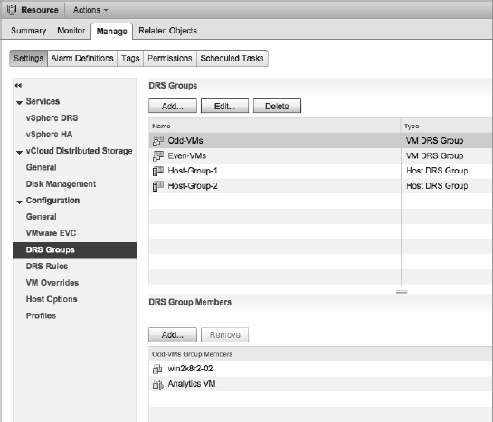
Before you can start creating a host affinity rule, you have to create at least one VM DRS group and at least one host DRS group. Figure 12.23 shows the DRS groups. As you can see, a few groups have already been defined.
FIGURE 12.23 The DRS Groups Manager allows you to create and modify VM DRS groups and host DRS groups.
Perform the following steps to create a VM or host DRS group:
- Launch the Web Client, if it is not already running, and connect to a vCenter Server instance.
- Navigate to the Hosts And Clusters view.
- Right-click the DRS-enabled cluster and select Settings.
- From the Settings pane, click DRS Groups.
- To create a DRS group, click the Add button.
- Supply a name for the new DRS group.
- Select the type of group from the drop-down list.
- Depending on the type of group, click add and select the appropriate VMs or hosts to add to the group, use the check box to select each one. If your cluster has a large number of VMs or hosts, there is a filter available in the top right of the dialog box.
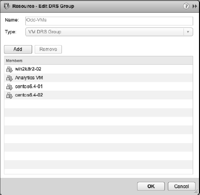
Figure 12.24 shows where we have added four VMs to a new VM DRS group.
- Click OK when you finish adding or removing VMs or hosts from the DRS group.
- Click OK in the cluster Settings dialog box to save the DRS groups and return to the Web Client.
FIGURE 12.24 Use the buttons to add or remove VMs or hosts from a DRS group. This screen shot shows VMs added to a DRS group.
The previous steps are the same for both VM DRS groups and host DRS groups, and you'll need to have at least one of each group defined before you can create the rule.
After you've defined your VM DRS groups and host DRS groups, you're ready to actually define the host affinity rule. The host affinity rule brings together a VM DRS group and a host DRS group along with the preferred rule behavior. There are four host affinity rule behaviors:
- Must Run On Hosts In Group
- Should Run On Hosts In Group
- Must Not Run On Hosts In Group
- Should Not Run On Hosts In Group
These rules are, for the most part, self-explanatory. Each rule is either mandatory (“Must”) or preferential (“Should”) plus affinity (“Run On”) or anti-affinity (“Not Run On”). Mandatory host affinity rules—those with “Must”—are honored not only by DRS but also by vSphere HA and vSphere DPM. For example, vSphere HA will not perform a failover if the failover would violate a required host affinity rule. Preferred rules, on the other hand, might be violated. Administrators have the option of creating an event-based alarm to monitor for the violation of preferred host affinity rules. You'll learn about alarms in Chapter 13, “Monitoring VMware vSphere Performance.”
Figure 12.25 shows a host affinity rule coming together with a selected VM DRS group, a rule behavior, and a selected host DRS group.
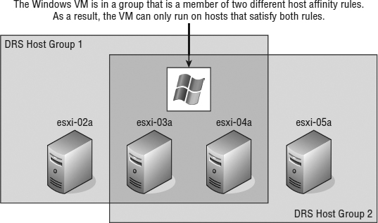
Be careful when defining host affinity rules, especially mandatory host affinity rules like the one shown in Figure 12.25, or you could run into a situation where VMs are severely limited on where they can run; this is illustrated in Figure 12.26.
FIGURE 12.25 This host affinity rule specifies that the selected group of VMs must run on the selected group of ESXi hosts.
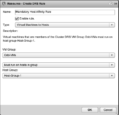
FIGURE 12.26 Administrators should ensure that using multiple required host affinity rules creates the desired results.
While the different sorts of rules that DRS supports provide lots of flexibility, there might be times when you need an even greater granularity. To satisfy that need for granularity, you can modify or disable DRS on individual VMs in the cluster.
CONFIGURING DRS VM OVERRIDES
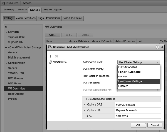
Although most VMs should be allowed to take advantage of the DRS balancing act, administrators may be adamant that certain enterprise-critical VMs are not DRS candidates. However, the VMs should remain in the cluster to take advantage of high-availability features provided by vSphere HA. In other words, VMs will take part in HA but not DRS despite both features being enabled on the cluster. As shown in Figure 12.27, VMs in a cluster can be configured with a VM Override.
FIGURE 12.27 Individual VMs can be prevented from participating in DRS.
Listed below DRS Groups and DRS Rules in the Cluster Settings pane is VM Overrides. This dialog box allows you to set HA and DRS settings on a per-VM basis that differ from the cluster settings. When you change settings in this way, although you can add them initially in batches of VMs, they are edited individually from then on. If you want more information on VM restart priority, host isolation, and VM monitoring, HA is discussed in Chapter 3 and Chapter 7.
Focusing on DRS, the following automation levels are available:
- Fully Automated
- Partially Automated
- Manual
- Use Cluster Settings
- Disabled
The first three options work as discussed previously in this chapter, in the sections “Understanding Manual Automation Behavior,” “Reviewing Partially Automated Behavior,” and “Examining Fully Automated Behavior.” The Disabled option turns off DRS, including the automatic host selection at startup and the migration recommendations. The default Use Cluster Settings option does just that; it configures the VM to accept the automation level set at the cluster.
Even if you exclude a VM or several VMs from participating in the automation of DRS, it is best not to set VMs to the Disabled option because no recommendations will be provided. A priority 2 recommendation could be provided that suggests moving a VM an administrator thought was best on a specific host to a different host suggested during the migration. For this reason, the Manual option is better. At least be open to the possibility that a VM might perform better on a different host.
VMware vSphere provides a number of tools to make administrators' lives easier, as long as you understand the tools and set them up properly. It might also be prudent to monitor the activities of these tools to see whether a change to the configuration might be warranted over time as your environment grows. Monitoring and alarms are discussed in detail in Chapter 13.
DRS is a valuable and useful part of vSphere, and it builds on vMotion to enable vSphere administrators to be more proactive about managing their environments.
Introducing and Working with Storage DRS
Building on the functionality that VMware introduced in earlier versions—specifically, building on Storage I/O Control and Storage vMotion—SDRS introduces the ability to perform automated balancing of storage utilization. SDRS can perform this automated balancing not only on the basis of space utilization but also on the basis of I/O load balancing.
Like vSphere DRS, SDRS is built on some closely related concepts and terms:
- Just as vSphere DRS uses clusters as a collection of hosts on which to act, SDRS uses datastore clusters as a collection of datastores on which it acts.
- Just as vSphere DRS can perform both initial placement and manual and ongoing balancing, SDRS also performs initial placement of VMDKs and ongoing balancing of VMDKs. The initial placement functionality of SDRS is especially appealing because it helps simplify the VM provisioning process for vSphere administrators.
- Just as vSphere DRS offers affinity and anti-affinity rules to influence recommendations, SDRS offers VMDK affinity and anti-affinity functionality.
As just mentioned, SDRS uses the idea of a datastore cluster—a group of datastores treated as shared storage resources—in order to operate. Before you can enable or configure SDRS, you must create a datastore cluster. However, you can't just arbitrarily combine datastores into a datastore cluster; there are some guidelines you need to follow.
Specifically, VMware provides the following guidelines for datastores that are combined into datastore clusters:
- Datastores of different sizes and I/O capacities can be combined in a datastore cluster. Although possible, we wouldn't recommend this practice unless you have very specific requirements. Additionally, datastores from different arrays and vendors can be combined into a datastore cluster. However, you cannot combine NFS and VMFS datastores in a datastore cluster.
- You cannot combine replicated and nonreplicated datastores into an SDRS-enabled datastore cluster.
- All hosts attached to a datastore in a datastore cluster must be running ESXi 5 or later. ESX/ESXi 4.x and earlier cannot be connected to a datastore that you want to add to a datastore cluster.
- Datastores shared across multiple datacenters are not supported for SDRS.
WHAT ABOUT MIXED HARDWARE ACCELERATION SUPPORT?
Hardware acceleration as a result of support for the vSphere Storage APIs for Array Integration (more commonly known as VAAI) is another factor to consider when creating datastore clusters. As a best practice, VMware recommends against mixing datastores that do support hardware acceleration with datastores that don't support hardware acceleration. All the datastores in a datastore cluster should be homogeneous with regard to hardware acceleration support in the underlying array(s).
Along with these general guidelines from VMware, we recommend you consult your specific storage array vendor for any additional recommendations that are particular to your specific array. Your storage vendors may have recommendations on what array-based features are or are not supported in conjunction with SDRS.
In the next section, we'll show you how to create and work with datastore clusters in preparation for a more in-depth look at configuring SDRS.
Creating and Working with Datastore Clusters
Now you're ready to create a datastore cluster and begin exploring SDRS in greater detail.
Perform these steps to create a datastore cluster:
- If it is not already running, launch the Web Client.
Storage DRS and datastore clusters are possible only when you are using vCenter Server in your environment.
- Navigate to the Storage view.
- Right-click the datacenter object where you want to create a new datastore cluster. Click New Datastore Cluster; this launches the New Datastore Cluster Wizard.
- Supply a name for the new datastore cluster.
- If you want to enable Storage DRS for this datastore, select Turn On Storage DRS. Click Next.
- Storage DRS can operate in a manual mode, where it will make recommendations only, or in Fully Automated mode, where it will actually perform storage migrations automatically. Select Fully Automated and click Next.
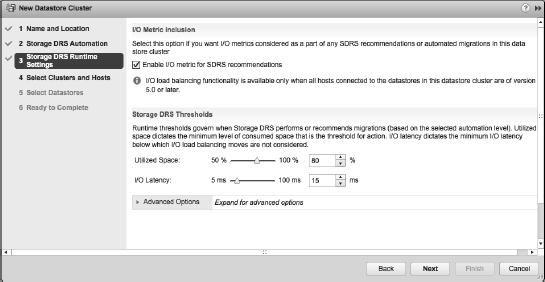
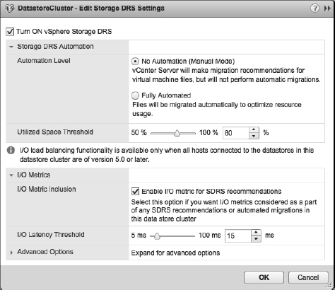
- If you want Storage DRS to include I/O metrics along with space utilization as part of its recommendations or migrations, select Enable I/O Metric For Storage DRS Recommendations.
Configuring SDRS to include I/O metrics in this manner will automatically enable Storage I/O Control on the datastores that are a part of this cluster.
- You can adjust the thresholds that Storage DRS uses to control when it recommends or performs migrations (depending on whether Storage DRS is configured for manual or fully automated operation).
The default utilized space threshold is 80 percent; this means when the datastore reaches 80 percent full, Storage DRS will recommend or perform a storage migration. The default setting for I/O latency is 15 ms; you should adjust this based on recommendations from your storage vendor. Figure 12.28 shows the default settings for the SDRS runtime rules. When you are finished adjusting these values, click Next.
FIGURE 12.28 The default settings for SDRS include I/O metrics and settings for utilized space and I/O latency.
STORAGE I/O CONTROL AND STORAGE DRS LATENCY THRESHOLDS
In Chapter 11 in the section “Enabling Storage I/O Control,” we discussed adjusting the threshold for Storage I/O Control (SIOC). You'll note that the default I/O latency threshold for SDRS (15 ms) is well below the default for SIOC (30 ms). The idea behind these default settings is that SDRS can make a migration to balance the load (if fully automated) before throttling becomes necessary.
Just as we recommended you check with your storage vendor for specific recommendations on SIOC latency values, you should also check with your array vendor to see if that vendor offers recommendations for SDRS latency values.
- Place a check in the check box next to the ESXi hosts and/or clusters to which this new datastore cluster should be added; then click Next.
- Select the available datastores you'd like to add to the new datastore cluster.
Because of the nature of Storage DRS, you'll want to leave the Show Datastores dropdown box at the default setting of Connected To All Hosts so that any datastores listed here are accessible from the hosts and/or clusters you selected in the previous step. Place a check in the check box next to each datastore you want added to the datastore cluster. Click Next.
- Review the settings in the final screen of the New Datastore Cluster Wizard.
If any of the settings are incorrect or if you need to make any changes, use the hyperlinks on the left to go back. Otherwise, click Finish.
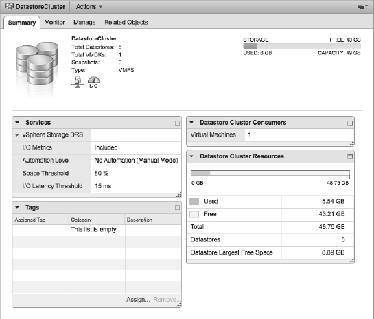
The newly created datastore cluster will appear in the Storage view. The Summary tab of the datastore cluster, shown in Figure 12.29, will display the aggregate statistics about the datastores in the datastore cluster.
FIGURE 12.29 The Summary tab of a datastore cluster provides overall information about total capacity, total used space, total free space, and largest free space.
Once you've created a datastore cluster, you can add capacity to it by adding more datastores, much in the same way you would add capacity to a vSphere DRS cluster by adding new ESXi hosts.
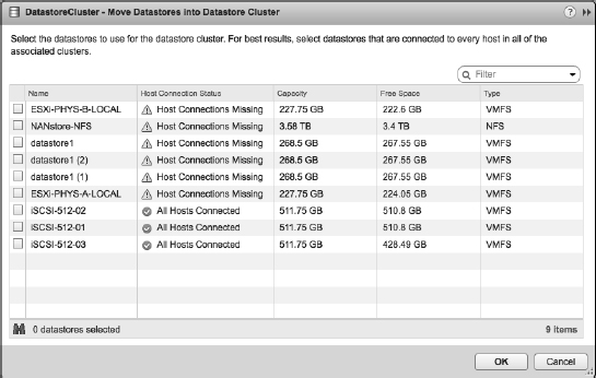
To add a datastore to a datastore cluster, just right-click an existing datastore cluster and select Move Datastores Into from the pop-up context menu. This opens the Move Datastores Into Cluster dialog box, where you can select additional datastores to add to the datastore cluster. Figure 12.30 shows the Move Datastores Into Datastore Cluster dialog box, where you can see that some datastores cannot be added because all necessary ESXi hosts aren't connected. This ensures that you don't inadvertently add a datastore to a datastore cluster and then find that an SRDS migration renders that VMDK unreachable by one or more ESXi hosts.
FIGURE 12.30 To add a datastore to a datastore cluster, the new datastore must be connected to all the hosts currently connected to the datastore cluster.
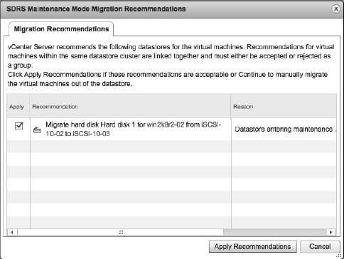
SDRS also offers a maintenance mode option for datastores, just as vSphere DRS offers a maintenance mode option for ESXi hosts. To place a datastore into SDRS maintenance mode, right-click the datastore and select All vCenter Actions ![]() Enter Maintenance Mode. If there are any registered VMs currently on that datastore, SDRS will immediately generate migration recommendations, as Figure 12.31 shows. If you select Cancel in the SDRS Maintenance Mode Migration Recommendations dialog box, you will cancel the SDRS maintenance mode request and the datastore will not go into SDRS maintenance mode.
Enter Maintenance Mode. If there are any registered VMs currently on that datastore, SDRS will immediately generate migration recommendations, as Figure 12.31 shows. If you select Cancel in the SDRS Maintenance Mode Migration Recommendations dialog box, you will cancel the SDRS maintenance mode request and the datastore will not go into SDRS maintenance mode.
FIGURE 12.31 Putting a datastore into SDRS maintenance mode generates SDRS recommendations to evacuate the datastore.
STORAGE DRS MAINTENANCE MODE DOESN'T AFFECT TEMPLATES AND ISOS
When you enable SDRS maintenance mode for a datastore, recommendations are generated for registered VMs. However, SDRS maintenance mode will not affect templates, unregistered VMs, or ISOs stored on that datastore.
In addition to using the Add Storage dialog box we showed you earlier in this section, you can use drag and drop to add a datastore to an existing datastore cluster. Note, however, that drag and drop won't warn you that you're adding a datastore that doesn't have connections to all the hosts that are currently connected to the datastore cluster, so we generally recommend using the Move Datastores Into Datastore Cluster dialog box shown in Figure 12.30.
Let's now take a more in-depth look at configuring SDRS to work with the datastore cluster(s) that you've created.
Configuring Storage DRS
All of the configuration for SDRS is done from the Manage ![]() Settings pane. You'll open the settings pane box by right-clicking a datastore cluster and selecting Settings or by clicking Settings on the Manage tab of a datastore cluster. Both methods will give you the same result. Within this pane, click the Edit button at the top right of the pane.
Settings pane. You'll open the settings pane box by right-clicking a datastore cluster and selecting Settings or by clicking Settings on the Manage tab of a datastore cluster. Both methods will give you the same result. Within this pane, click the Edit button at the top right of the pane.
From the settings pane, you can accomplish the following tasks:
- Enable or disable SDRS
- Configure the SDRS automation level
- Change or modify the SDRS runtime rules
- Configure or modify custom SDRS schedules
- Create SDRS rules to influence SDRS behavior
- Configure per-VM SDRS settings
The following sections examine each of these areas in more detail.
ENABLING OR DISABLING STORAGE DRS
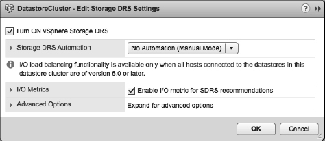
From the Edit dialog box, you can easily enable or disable SDRS. Figure 12.32 shows this area of the Edit dialog box. From here, you can enable SDRS by selecting Turn ON vSphere Storage DRS. If Storage DRS is already enabled, you can deselect Turn ON vSphere Storage DRS to disable it. If you disable SDRS, the SDRS settings are preserved. If SDRS is later reenabled, the configuration is returned to the point where it was when it was disabled.
FIGURE 12.32 In addition to enabling or disabling Storage DRS, you can enable or disable I/O metrics for SDRS recommentations from this dialog box.
CONFIGURING STORAGE DRS AUTOMATION
SDRS offers two predefined automation levels, as you can see in Figure 12.33: No Automation (Manual Mode) and Fully Automated.
FIGURE 12.33 Storage DRS offers both Manual and Fully Automated modes of operation.
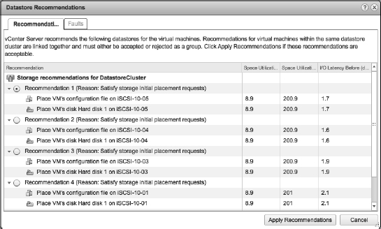
When the SDRS automation level is set to No Automation (Manual Mode), SDRS will generate recommendations for initial placement and for storage migrations based on the configured space and I/O thresholds. Initial placement recommendations occur when you create a new VM (and thus a new virtual disk), add a virtual disk to a VM, or clone a VM or template. The recommendations appear in a pop-up window, like the one shown in Figure 12.34.
FIGURE 12.34 Storage DRS presents a list of initial placement recommendations whenever a new virtual disk is created.
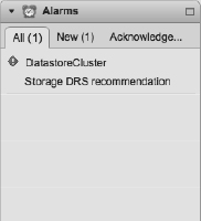
Recommendations for storage migrations are noted in two different ways. First, an alarm is generated to note that an SDRS recommendation is present. You can view this alarm on the Monitor ![]() Issues tab of the datastore cluster in Storage view. The alarm is shown in Figure 12.35.
Issues tab of the datastore cluster in Storage view. The alarm is shown in Figure 12.35.
FIGURE 12.35 This alarm on the datastore cluster indicates that an SDRS recommendation is present.
In addition, the Monitor ![]() Storage DRS tab of the datastore cluster (visible in Storage view, as shown in Figure 12.36) will list the current SDRS recommendations and give you the option to apply those recommendations—that is, initiate the suggested Storage vMotion migrations.
Storage DRS tab of the datastore cluster (visible in Storage view, as shown in Figure 12.36) will list the current SDRS recommendations and give you the option to apply those recommendations—that is, initiate the suggested Storage vMotion migrations.
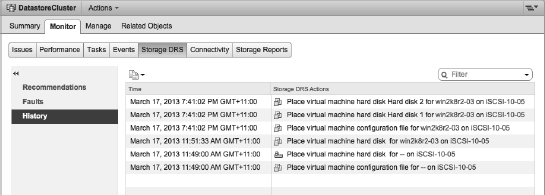
When SDRS is configured for Fully Automated mode, it will automatically initiate Storage vMotion migrations instead of generating recommendations for the administrator to approve. In this instance, you can use the Monitor ![]() Storage DRS tab of the datastore cluster to view the history of SDRS actions by selecting the History button at the top of the Storage DRS tab. Figure 12.37 shows the SDRS history for the selected datastore cluster.
Storage DRS tab of the datastore cluster to view the history of SDRS actions by selecting the History button at the top of the Storage DRS tab. Figure 12.37 shows the SDRS history for the selected datastore cluster.
To modify how aggressive SDRS is when running in Fully Automated mode, expand the rules section of the Edit dialog box, described in the next section.
MODIFYING THE STORAGE DRS RUNTIME BEHAVIOR
In the SDRS Edit dialog box, you have several options for modifying the behavior of SDRS.
First, if you'd like to tell SDRS to operate only on the basis of space utilization and not I/O utilization, simply deselect Enable I/O Metric For SDRS Recommendations. This will tell SDRS to recommend or perform (depending on the automation level) migrations based strictly on space utilization.
FIGURE 12.36 Click Apply Recommendations in the Storage DRS tab to initiate the storage migrations suggested by SDRS.
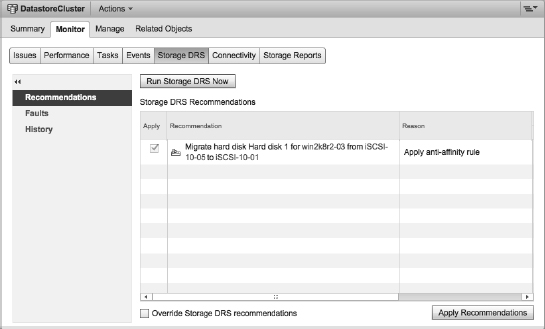
FIGURE 12.37 On the Storage DRS tab of a datastore cluster, use the History button to review the SDRS actions that have taken place when SDRS is running in Fully Automated mode.
Second, the two Storage DRS Thresholds settings allow you to adjust the thresholds that SDRS uses to recommend or perform migrations. By default, the Utilized Space setting is 80 percent, meaning that SDRS will recommend or perform a migration when a datastore reaches 80 percent full. The default I/O Latency setting is 15 ms; when latency measurements exceed 15 ms for a given datastore in a datastore cluster and I/O metrics are enabled, then SDRS will recommend or perform a storage migration to another datastore with a lower latency measurement.
If you click the arrow next to Advanced Options, you can further fine-tune the runtime behavior of SDRS:
- Keep VMDKs Together By Default is fairly self-explanatory. By default VM virtual disks (VMDKs) should be kept together unless there is a specific need to always split them between datastores.
- The Check Imbalances Every option allows you to control how often SDRS evaluates the I/O or space utilization in order to make a recommendation or perform a migration.
- The I/O Imbalance Threshold controls the aggressiveness of the SDRS algorithm. As the slider is moved toward Aggressive and the counter increases, this moves up the priority of the recommendation that will be automatically acted on when SDRS is running in Fully Automated mode.
- Minimum Space Utilization Difference is a slider bar that lets you specify how much of an improvement SDRS should look for before making a recommendation or performing a migration. The setting defaults to 5 percent. This means that if the destination's values are 5 percent lower than the source's values, SDRS will make the recommendation or perform the migration.
In addition to the rudimentary schedule control that controls how often SDRS evaluates I/O and space utilization, you can create more complex scheduling settings.
CONFIGURING OR MODIFYING THE STORAGE DRS SCHEDULE
The Schedule Storage DRS button next to the Edit button allows you to create custom schedules. These custom schedules enable vSphere administrators to specify times when the SDRS behavior should be different. For example, are there times when SDRS should be running in No Automation (Manual Mode)? Are there times when the space utilization or I/O latency thresholds should be different? If so, and you need SDRS to adjust to these recurring differences, you can accommodate that through custom SDRS schedules.
Let's look at an example. Let's say that you normally have SDRS running in Fully Automated mode, and it works fine. However, at night, when backups are running, you want SDRS not to automatically perform storage migrations. Using a custom SDRS schedule, you can tell SDRS to switch into manual mode during certain times of the day and days of the week and then return into Fully Automated mode when that day/time period is over.
Perform the following steps to create a custom SDRS schedule:
- If it's not already running, launch the Web Client.
- Navigate to the Storage view.
- Right-click a datastore cluster and select Settings.
- Select Schedule Storage DRS from the pane on the right. This opens the Edit Storage DRS Settings (scheduled) Wizard.
- Select the settings that you want to activate for this schedule. Click Scheduling options on the left to continue.
- Provide a task name and a task description. Now click the Change hyperlink to set the schedule.
- Specify the time when this custom schedule task should be active.
For example, if you needed to change SDRS behavior while backups are running in the middle of the night, you could select Setup A Reoccurring Schedule For This Action and set the time to 10:00 PM weekly. Then you select the check box for every weekday and click OK to close the Scheduler.
- Review the settings. Click OK if they are correct.
After you complete the Schedule Storage DRS Task Wizard, a new set of entries appears in the scheduling list for SDRS, as illustrated in Figure 12.38. Typically, as with this example, you will want to schedule two tasks, one for changing the setting and another for setting it back.
FIGURE 12.38 SDRS scheduling entries allow you to automatically change the settings for SDRS on certain days and at certain times.
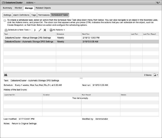
The ability to configure SDRS differently at different times or on different days is a powerful feature that will let vSphere administrators customize SDRS behaviors to best suit their environments. SDRS rules are another tool that provide administrators with more control over how SDRS handles VMs and virtual disks, as you'll see in the next section.
CREATING STORAGE DRS RULES
Just as vSphere DRS has affinity and anti-affinity rules, SDRS offers vSphere administrators the ability to create VMDK affinity and anti-affinity rules and VM anti-affinity rules. These rules modify the behavior of SDRS to ensure that specific VMDKs are always kept together (VMDK affinity rule) or separate (VMDK anti-affinity rule) or that all the virtual disks from certain VMs are kept separate (VM anti-affinity rule).
Perform these steps to create an SDRS VMDK affinity or anti-affinity or SDRS VM anti-affinity rule:
- In the Web Client, navigate to the Hosts And Clusters inventory view.
- Right-click a VM and select Edit Settings.
- Select SRDS Rules.
- Click Add to add a rule.
- In the Rule dialog box, supply a name for the rule you are creating.
- From the Type drop-down box, select VMDK affinity, VMDK Anti-Affinity, or VM Anti-Affinity, depending on which type of rule you want to create.
For the purpose of this procedure, select VMDK Anti-Affinity.
- Select the virtual disks that you want to include in this rule, as shown in Figure 12.39, and then click OK.
FIGURE 12.39 An SDRS VMDK anti-affinity rule allows you to specify particular virtual disks for a VM that should be kept on separate datastores in a datastore cluster.
- Click OK in the Edit SDRS Rule dialog box to complete the creation of the SDRS anti-affinity rule.
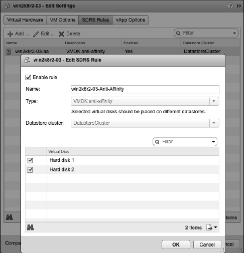
SETTING STORAGE DRS VM OVERRIDES
Just like DRS, Storage DRS can override cluster settings on a per-VM level through the VM Overrides feature. If you need to apply different settings on a particular VM or group of VMs, VM Overrides give you this granular level of control.
Within the Datastore Cluster ![]() Manage
Manage ![]() Settings tab, select the VM Overrides option. Here you can add, edit, or delete override rules for individual VMs, as shown in Figure 12.40.
Settings tab, select the VM Overrides option. Here you can add, edit, or delete override rules for individual VMs, as shown in Figure 12.40.
FIGURE 12.40 The per VM Overrides area shows which VMs differ from the SDRS cluster settings.
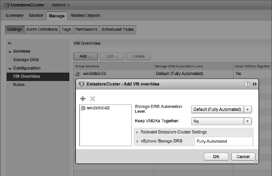
DRS EVALUATION SCHEDULE
Normally, Storage DRS runs an evaluation every 8 hours (this can be adjusted; refer back to the section “Modifying the Storage DRS Runtime Behavior”). Storage DRS will include the new anti-affinity rule in the next evaluation. If you want to invoke SDRS immediately, the Storage DRS tab of the datastore cluster, shown in Figure 12.41, offers the option to invoke SDRS immediately using the Run Storage DRS link.
FIGURE 12.41 Use the Run Storage DRS link to invoke SDRS on demand.
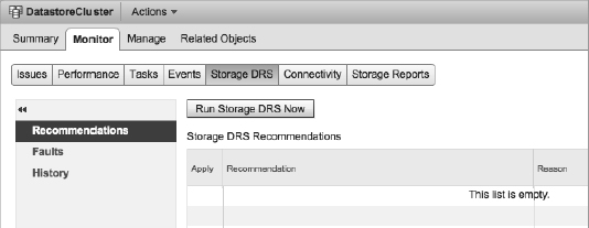
As you can see, SDRS has a tremendous amount of flexibility built into it to allow vSphere administrators to harness the power of SDRS by tailoring its behavior to best suit their specific environments.
In the next chapter, we'll move into a review and discussion of monitoring and alarms and show what tools or features VMware vSphere offers administrators in the realm of performance monitoring.
The Bottom Line
Configure and execute vMotion. vMotion is a feature that allows running VMs to be migrated from one physical ESXi host to another physical ESXi host with no downtime to end users. To execute vMotion, you must make sure both the ESXi hosts and the VMs meet specific configuration requirements. In addition, vCenter Server performs validation checks to ensure that vMotion compatibility rules are observed.
Master It A certain vendor has just released a series of patches for some of the guest OSes in your virtualized infrastructure. You request an outage window from your supervisor, but your supervisor says to just use vMotion to prevent downtime. Is your supervisor correct? Why or why not?
Master It Is vMotion a solution to prevent unplanned downtime?
Ensure vMotion compatibility across processor families. vMotion requires compatible CPU families on the source and destination ESXi hosts in order to be successful. To help alleviate any potential problems resulting from changes in processor families over time, vSphere offers Enhanced vMotion Compatibility (EVC), which can mask differences between CPU families to maintain vMotion compatibility.
Master It Can you change the EVC level for a cluster while there are VMs running on hosts in the cluster?
Use Storage vMotion. Just as vMotion is used to migrate running VMs from one ESXi host to another, Storage vMotion is used to migrate the virtual disks of a running VM from one datastore to another. You can also use Storage vMotion to convert between thick and thin virtual disk types.
Master It Name two features of Storage vMotion that would help administrators cope with storage-related changes in their vSphere environment.
Perform combined vMotion and Storage vMotion. Using vMotion and Storage at the same time gives you greater flexibility when migrating VMs between hosts. Utilizing this feature can also save time when you must evacuate a host for maintenance.
Master It A fellow administrator is trying to migrate a VM to a different datastore and a different host while it is running and wishes to complete the task as quickly and as simply as possible. Which migration option should she choose?
Configure and manage vSphere Distributed Resource Scheduler. vSphere Distributed Resource Scheduler enables vCenter Server to automate the process of conducting vMotion migrations to help balance the load across ESXi hosts within a cluster. You can automate DRS as you wish, and vCenter Server has flexible controls for affecting the behavior of DRS and specific VMs within a DRS-enabled cluster.
Master It You want to take advantage of vSphere DRS to provide some load balancing of virtual workloads within your environment. However, because of business constraints, you have a few workloads that should not be automatically moved to other hosts using vMotion. Can you use DRS? If so, how can you prevent these specific workloads from being affected by DRS?
Configure and manage Storage DRS. Building on Storage vMotion just as vSphere DRS builds on vMotion, Storage DRS automates the process of balancing storage capacity and I/O utilization. Storage DRS uses datastore clusters and can operate in Manual or Fully Automated mode. Numerous customizations exist—such as custom schedules, VM and VMDK anti-affinity rules, and threshold settings—to allow administrators to fine-tune the behavior of Storage DRS for their specific environments.
Master It Name the two ways in which an administrator is notified that a Storage DRS recommendation has been generated.
Master It What is a potential disadvantage of using drag-and-drop to add a datastore to a datastore cluster?