Chapter 5
Creating and Configuring a vSphere Network
Eventually, it all comes back to the network. Having servers running VMware ESXi with virtual machines stored on a highly redundant storage is great, but they're ultimately useless if the virtual machines can't communicate across the network. What good is the ability to run 10, 20, 30, or more production servers on a single ESXi host if those production servers aren't available to clients on the network? Clearly, vSphere networking within ESXi is a key area for every vSphere administrator to understand fully.
Putting Together a vSphere Network
Designing and building vSphere networks with ESXi and vCenter Server bears some similarities to designing and building physical networks, but there are enough significant differences that an overview of components and terminology is warranted. Before addressing some of the factors that affect network design in a virtual environment, let's define the components that may be used to build your virtual network.
- vSphere Standard Switch A software-based switch that resides in the VMkernel and provides traffic management for virtual machines. Users must manage vSphere Standard Switches independently on each ESXi host. In this book, the term vSwitch also refers to a vSphere Standard Switch.
- vSphere Distributed Switch A software-based switch that resides in the VMkernel and provides traffic management for virtual machines and the VMkernel. vSphere Distributed Switches are shared by and managed across ESXi hosts and clusters within a vSphere datacenter. You might see vSphere Distributed Switch abbreviated as VDS; this book will use VDS, vSphere Distributed Switch, or just distributed switch.
- Port/Port Group A logical object on a vSphere Standard or Distributed Switch that provides specialized services for the VMkernel or virtual machines. A virtual switch can contain a VMkernel port or a Virtual Machine Port Group. On a vSphere Distributed Switch, these are called distributed port groups.
- VMkernel Port A specialized virtual switch port type that is configured with an IP address to allow hypervisor management traffic, vMotion, VMware vSAN, iSCSI storage, Network File System (NFS) storage, vSphere Replication, and vSphere Fault Tolerance (FT) logging. VMkernel ports are also created for VXLAN tunnel endpoints (VTEPs) as used by the VMware NSX network virtualization and security platform. These VMkernel ports are created with the VXLAN TCP/IP stack rather than using the default stack. TCP/IP stacks are covered a bit later in the chapter. A VMkernel port is also referred to as a vmknic.
- Virtual Machine Port Group A group of virtual switch ports that share a common configuration and allow virtual machines to access other virtual machines that are configured on the same port group or accessible PVLAN or on the physical network.
- Virtual LAN (VLAN) A logical local area network configured on a virtual or physical switch that provides efficient traffic segmentation, broadcast control, security, and efficient bandwidth utilization by providing traffic only to the ports configured for that particular VLAN.
- Trunk Port (Trunking) A port on a physical switch that listens for and knows how to pass traffic for multiple VLANs. It does so by maintaining the 802.1q VLAN tags for traffic moving through the trunk port to the connected device(s). Trunk ports are typically used for switch-to-switch connections to allow VLANs to pass freely between switches. Virtual switches support VLANs, and using VLAN trunks enables the VLANs to pass freely into the virtual switches.
- Access Port A port on a physical switch that passes traffic for only a single VLAN. Unlike a trunk port, which maintains the VLAN identification for traffic moving through the port, an access port strips away the VLAN information for traffic moving through the port.
- Network Interface Card Team The aggregation of physical network interface cards (NICs) to form a single logical communication channel. Different types of NIC teams provide varying levels of traffic load balancing and fault tolerance.
- VMXNET Adapter A virtualized network adapter operating inside a guest operating system (guest OS). The VMXNET adapter is optimized for performance in a virtual machine. VMware Tools are required to be installed in the guest OS to provide the VMXNET driver. The VMXNET adapter is sometimes referred to as a paravirtualized driver.
- VMXNET 2 Adapter The VMXNET 2 adapter is based on the VMXNET adapter but provides some high-performance features commonly used on modern networks, such as jumbo frames and hardware offloads. VMware Tools are required to be installed in the guest OS to provide the VMXNET driver.
- VMXNET 3 Adapter The VMXNET 3 adapter is the next-generation paravirtualized NIC, designed for performance, and is not related to VMXNET or VMXNET 2. It offers all the features available in VMXNET 2 and adds several new features like multiqueue support (also known as Receive Side Scaling in Windows), IPv6 offloads, and MSI/MSI-X interrupt delivery. VMXNET 3 requires virtual machine hardware version 7 or later as well as VMware Tools installed in the guest OS to provide the VMXNET driver.
- E1000 Adapter A virtualized network adapter that emulates the Intel 82545EM Gigabit network adapter. Typically, the guest OS provides a built-in driver.
- E1000e Adapter A virtualized network adapter that emulates the Intel 82574 Gigabit network adapter. The E1000e requires virtual machine hardware version 8 or later. The E1000e adapter is available for Windows 8 and newer operating systems and is not available for Linux.
Now that you have a better understanding of the components involved and the terminology that you'll see in this chapter, let's examine how these components work together in support of virtual machines, IP-based storage, and ESXi hosts.
Your answers to the following questions will, in large part, determine the design of your vSphere network:
- Do you have or need a dedicated network for management traffic, such as for the management of physical switches?
- Do you have or need a dedicated network for vMotion traffic?
- Do you have an IP storage network? Is this IP storage network a dedicated network? Are you running iSCSI or NFS? Are you planning on implementing VMware vSAN?
- How many NICs are standard in your ESXi host design?
- Do the NICs in your hosts run 1 Gb Ethernet, 10 Gb Ethernet, 25 Gb Ethernet, or 40 Gb Ethernet?
- Do you need extremely high levels of fault tolerance for virtual machines?
- Is the existing physical network composed of VLANs?
- Do you want to extend the use of VLANs into the virtual switches?
- Will you be introducing an overlay, such as VXLAN or Geneve, into your network through the use of NSX?
As a precursor to setting up a vSphere networking architecture, you need to identify and document the physical network components and the security needs of the network. It's also important to understand the architecture of the existing physical network because that also greatly influences the design of the vSphere network. If the physical network can't support the use of VLANs, for example, then the vSphere network's design has to account for that limitation.
Throughout this chapter, as we discuss the various components of a vSphere network in more detail, we'll also provide guidance on how the various components fit into an overall vSphere network design. A successful vSphere network combines the physical network, NICs, and vSwitches, as shown in Figure 5.1.

FIGURE 5.1 Successful vSphere networking is a blend of virtual and physical network adapters and switches.
Because the vSphere network implementation makes virtual machines accessible, it is essential that the vSphere network be configured in a way that supports reliable and efficient communication around the various network infrastructure components.
Working with vSphere Standard Switches
The networking architecture of ESXi revolves around creating and configuring virtual switches. These virtual switches are either a vSphere Standard Switch or a vSphere Distributed Switch. First, we'll discuss the vSphere Standard Switch, and then we'll discuss the vSphere Distributed Switch.
You create and manage vSphere Standard Switches through the vSphere Web Client or through the vSphere CLI using the esxcli command, but they operate within the VMkernel. Virtual switches provide the connectivity for network communications, such as:
- Between virtual machines within an ESXi host
- Between virtual machines on different ESXi hosts
- Between virtual machines and other virtual or physical network identities connected via the physical network
- For VMkernel access to networks for Management, vMotion, VMware vSAN, iSCSI, NFS, vSphere Replication, or fault tolerance logging
Take a look at Figure 5.2, which shows the vSphere Web Client depicting a vSphere Standard Switch on an ESXi host. In this figure, the vSphere Standard Switch isn't depicted alone; it also depicts port groups and uplinks for communication external to the host. Without uplinks, a virtual switch can't communicate with the upstream network; without port groups, a vSphere Standard Switch can't provide connectivity for the VMkernel or the virtual machines. It is for this reason that most of our discussion on virtual switches centers on port groups and uplinks.
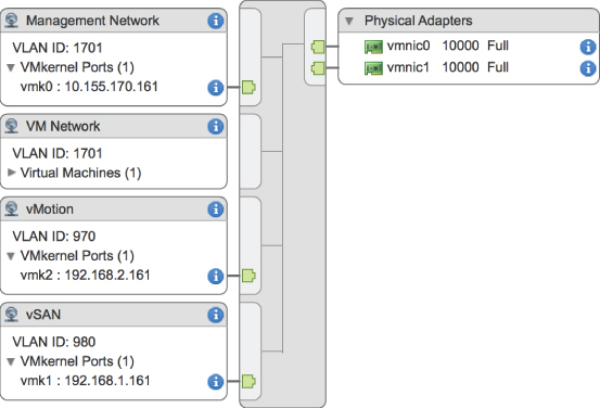
FIGURE 5.2 vSphere Standard Switches alone don't provide connectivity; they need port groups and uplinks to provide connectivity external to the ESXi host.
First, though, let's take a closer look at virtual switches and how they are similar to, and yet different from, physical switches in the network.
Comparing Virtual Switches and Physical Switches
Virtual switches in ESXi are constructed by and operate in the VMkernel. Virtual switches are not managed switches and do not provide all the advanced features that many new physical switches provide. You cannot, for example, telnet into a vSwitch to modify settings. There is no command-line interface (CLI) for a vSwitch, apart from vSphere CLI commands such as esxcli or PowerCLI commands such as New-VirtualPortGroup. Even so, a vSwitch operates like a physical switch in some ways. Like its physical counterpart, a vSwitch functions at Layer 2, maintains MAC address tables, forwards frames to other switch ports based on the MAC address, supports VLAN configurations, can trunk VLANs using IEEE 802.1q VLAN tags, and can establish port channels. A vSphere Distributed Switch also supports PVLANs, providing there is PVLAN support on the upstream physical switches. Similar to physical switches, vSwitches are configured with a specific number of ports.
Despite these similarities, vSwitches do differ somewhat from physical switches. A vSphere Standard Switch does not support the use of dynamic negotiation protocols for establishing 802.1q trunks or port channels, such as Dynamic Trunking Protocol (DTP) or Link Aggregation Control Protocol (LACP). Although the vSphere Distributed Switch does support LACP in both Active and Passive modes. A vSwitch cannot be connected to another vSwitch, thereby eliminating a potential loop configuration. Because there is no possibility of looping, the vSwitches do not run Spanning Tree Protocol (STP).
It is possible to link vSwitches together using a virtual machine with Layer 2 bridging software and multiple virtual NICs, but this is not an accidental configuration and would require some effort to establish.
- vSwitches and physical switches have some other differences: A vSwitch authoritatively knows the MAC addresses of the virtual machines connected to it, so there is no need to learn MAC addresses from the network.
- Traffic received by a vSwitch on one uplink is never forwarded out another uplink. This is yet another reason why vSwitches do not run STP.
- A vSwitch does not need to perform Internet Group Management Protocol (IGMP) snooping, because it knows the multicast interests of the virtual machines attached to it.
As you can see from this list of differences, you simply can't use virtual switches in the same way you can use physical switches. You can't use a virtual switch as a transit path between two physical switches, for example, because traffic received on one uplink won't be forwarded out another uplink.
With this basic understanding of how vSwitches work, let's now take a closer look at ports and port groups.
Understanding Ports and Port Groups
As described earlier, a vSwitch allows several different types of communication, including communication to and from the VMkernel and between virtual machines. To help distinguish between these different types of communication, ESXi hosts use ports and port groups. A vSphere Standard Switch without any ports or port groups is like a physical switch that has no physical ports; there is no way to connect anything to the switch, and it therefore serves no purpose.
Port groups differentiate between the types of traffic passing through a vSwitch, and they also operate as a boundary for communication and/or security policy configuration. Figure 5.3 and Figure 5.4 show the two different types of ports and port groups that you can configure on a vSwitch:
- VMkernel port
- Virtual machine port group

FIGURE 5.3 Virtual switches can contain two connection types, a VMkernel port and a virtual machine port group.

FIGURE 5.4 You can create virtual switches with both connection types on the same switch.
Because a vSwitch cannot be used in any way without at least one port or port group, you'll see that the vSphere Web Client combines the creation of new vSwitches with the creation of new ports or port groups.
As previously shown in Figure 5.2, though, ports and port groups are only part of the overall solution. The uplinks are the other part of the solution that you need to consider, because they provide external network connectivity to the vSwitches.
Understanding Uplinks
Although a vSwitch allows communication between virtual machines connected to the vSwitch, it cannot communicate with the physical network without uplinks. Just as a physical switch must be connected to other switches to communicate across the network, vSwitches must be connected to the ESXi host's physical NICs as uplinks to communicate with the rest of the network.
Unlike ports and port groups, uplinks aren't required for a vSwitch to function. Physical systems connected to an isolated physical switch with no uplinks to other physical switches in the network can still communicate with each other—just not with any other systems that are not connected to the same isolated switch. Similarly, virtual machines connected to a vSwitch without any uplinks can communicate with each other but not with virtual machines on other vSwitches or physical systems.
This sort of configuration is known as an internal-only vSwitch. It can be useful to allow virtual machines to communicate only with each other. Virtual machines that communicate through an internal-only vSwitch do not pass any traffic through a physical adapter on the ESXi host. As shown in Figure 5.5, communication between virtual machines connected to an internal-only vSwitch takes place entirely in software and happens at the speed at which the VMkernel can perform the task.
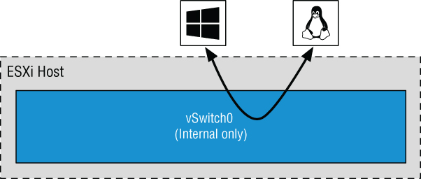
FIGURE 5.5 Virtual machines communicating through an internal-only vSwitch do not pass any traffic through a physical adapter.
For virtual machines to communicate with resources beyond the virtual machines hosted on the local ESXi host or when PVLAN is enabled, a vSwitch must be configured to use at least one physical network adapter, or uplink. A vSwitch can be bound to a single network adapter or bound to two or more network adapters.
A vSwitch bound to at least one physical network adapter allows virtual machines to establish communication with physical servers on the network or with virtual machines on other ESXi hosts. That's assuming, of course, that the virtual machines on the other ESXi hosts are connected to a vSwitch that is bound to at least one physical network adapter. Just like a physical network, a virtual network requires connectivity from end to end. Figure 5.6 shows the communication path for virtual machines connected to a vSwitch bound to a physical network adapter. In the diagram, when vm1 on sfo01m01esx01 needs to communicate with vm2 sfo01m01esx02, the traffic from the virtual machine passes through vSwitch0 (via a virtual machine port group) to the physical network adapter to which the vSwitch is bound. From the physical network adapter, the traffic will reach the physical switch (PhySw1). The physical switch (PhySw1) passes the traffic to the second physical switch (PhySw2), which will pass the traffic through the physical network adapter associated with the vSwitch on sfo01m01esx02. In the last stage of the communication, the vSwitch will pass the traffic to the destination virtual machine vm2.

FIGURE 5.6 A vSwitch with a single network adapter allows virtual machines to communicate with physical servers and other virtual machines on the network.
The vSwitch associated with a physical network adapter provides virtual machines with the amount of bandwidth the physical adapter is configured to support. All the virtual machines will share this bandwidth when communicating with physical machines or virtual machines on other ESXi hosts. In this way, a vSwitch is once again similar to a physical switch. For example, a vSwitch with a single 1 Gbps network adapter will provide up to 1 Gbps of bandwidth for the virtual machines connected to it; similarly, a physical switch with a 1 Gbps uplink to another physical switch provides up to 1 Gbps of bandwidth between the two switches for systems attached to the physical switches.
A vSwitch can also be configured with multiple physical network adapters.
Figure 5.7 and Figure 5.8 show a vSwitch configured with multiple physical network adapters. A vSwitch can have a maximum of 32 uplinks. In other words, a single vSwitch can use up to 32 physical network adapters to send and receive traffic to and from the physical network. Configuring multiple physical network adapters on a vSwitch offers the advantage of redundancy and load distribution. In the section “Configuring NIC Teaming,” later in this chapter, we'll dig deeper into this sort of vSwitch configuration.
- NOTE It's important to note that NIC teaming is a policy for how traffic is handled on multiple uplinks and not necessarily a type link aggregation such as LACP.

FIGURE 5.7 A vSwitch using NIC teaming has multiple available adapters for data transfer. NIC teaming offers redundancy and load distribution.

FIGURE 5.8 Virtual switches using NIC teaming are identified by the multiple physical network adapters assigned to the vSwitch.
We've examined vSwitches, ports and port groups, and uplinks, and you should have a basic understanding of how these pieces begin to fit together to build a virtual network. The next step is to delve deeper into the configuration of the various types of ports and port groups, because they are essential to vSphere networking. We'll start with a discussion on the management network.
Configuring the Management Network
Management traffic is a special type of network traffic that runs across a VMkernel port. VMkernel ports provide network access for the VMkernel's TCP/IP stack, which is separate and independent from the network traffic generated by virtual machines. The ESXi hosts management network, however, is treated a bit differently than other VMkernel ports in two ways:
- First, the ESXi management VMkerel port is automatically created when you install ESXi. In order for the ESXi host to be reachable across the network, a management VMkernel port must be configured and working.
- Second, the Direct Console User Interface (DCUI)—the user interface that exists when you're working at the physical console of a server running ESXi—provides a mechanism for configuring or reconfiguring the management network (Management VMKernel port) but not any other forms of networking on that host, apart from a few options for resetting network configuration.
Although the vSphere Web Client offers an option to enable management traffic when configuring networking, as you can see in Figure 5.9, it's unlikely that you'll use this option very often. After all, for you to configure management networking from within the vSphere Web Client, the ESXi host must already have functional management networking in place (vCenter Server communicates with ESXi hosts over the management network). You might use this option if you were creating additional management interfaces. To do this, you would use the procedure described later (in the section “Configuring VMkernel Networking”) to create VMkernel ports with the vSphere Web Client, simply enabling Management Traffic in the Enable Services section while creating the VMkernel port.
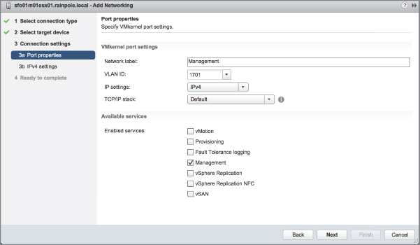
FIGURE 5.9 The vSphere Web Client offers a way to enable Management networking when configuring networking.
In the event the ESXi host is unreachable—and therefore cannot be configured using the vSphere Web Client—you'll need to use the DCUI to configure the management network.
Perform the following steps to configure the ESXi management network using the DCUI:
- At the server's physical console or using a remote console utility such as HP iLO, or Dell DRAC, press F2 to enter the System Customization menu.
When prompted to log in, enter the appropriate credentials.
- Use the arrow keys to highlight the Configure Management Network option, as shown in Figure 5.10, and press Enter.
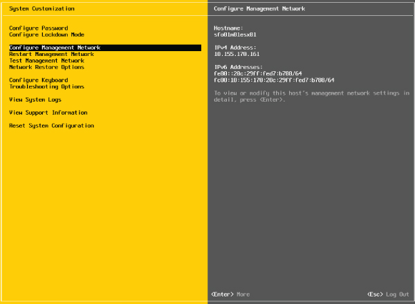
FIGURE 5.10 Configure ESXi's Management Network using the Configure Management Network option in the System Customization menu.
- From the Configure Management Network menu, select the appropriate option for configuring ESXi management networking, as shown in Figure 5.11.
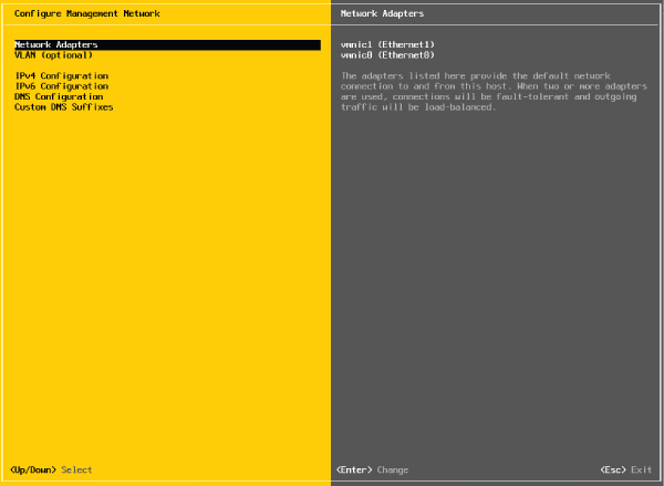
FIGURE 5.11 From the Configure Management Network menu, users can modify assigned network adapters, change the VLAN ID, IP address, DNS Servers, and DNS search configuration.
You cannot create additional management network interfaces from here; you can only modify the existing management network interface.
- When finished, follow the screen prompts to exit the management networking configuration.
If prompted to restart the management networking, select Yes; otherwise, restart the management networking from the System Customization menu, as shown in Figure 5.12.
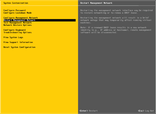
FIGURE 5.12 The Restart Management Network option restarts ESXi's management networking and applies any changes that were made.
In looking at Figure 5.10 and Figure 5.12, you'll also see options for testing the management network, which lets you verify that the management network is configured correctly. This is invaluable if you are unsure of the VLAN ID or network adapters that you should use.
Also notice the Network Restore Options screen, shown in Figure 5.13. This screen lets you restore the network configuration to defaults, restore a vSphere Standard Switch, or even restore a vSphere Distributed Switch—all very handy options if you are troubleshooting management network connectivity to your ESXi host.
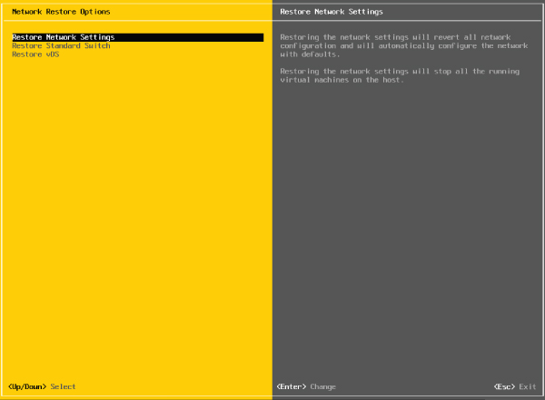
FIGURE 5.13 Use the Network Restore Options screen to manage network connectivity to an ESXi host.
Let's move our discussion of VMkernel networking away from just management traffic and take a closer look at the other types of VMkernel traffic, as well as how to create and configure VMkernel ports.
Configuring VMkernel Networking
VMkernel networking carries management traffic, but it also carries all other forms of traffic that originate with the ESXi host itself (i.e., any traffic that isn't generated by virtual machines running on that ESXi host). As shown in Figure 5.14 and Figure 5.15, VMkernel ports are used for Management, vMotion, vSAN, iSCSI, NFS, vSphere Replication, and vSphere FT, basically, all types of traffic that are generated by the hypervisor itself. Chapter 6, “Creating and Configuring Storage Devices,” details the iSCSI and NFS configurations as well as vSAN configurations. Chapter 12 provides details on the vMotion process and how vSphere FT works. These discussions provide insight into the traffic flow between VMkernel and storage devices (iSCSI/NFS/ vSAN) or other ESXi hosts (for vMotion or vSphere FT). At this point, you should be concerned only with configuring VMkernel networking.
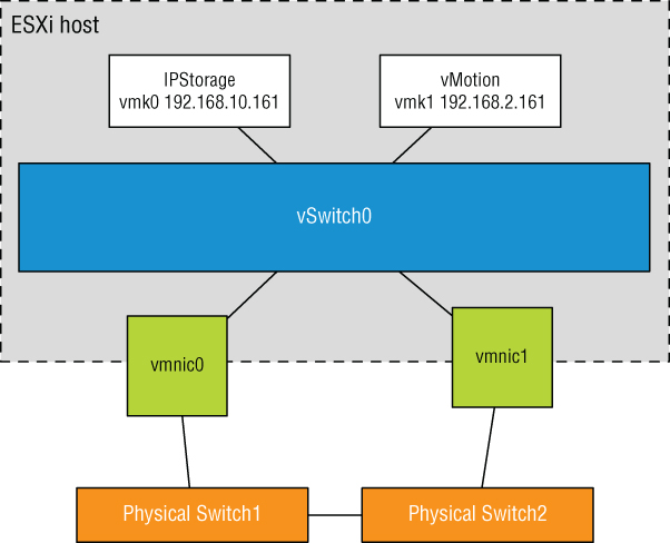
FIGURE 5.14 A VMkernel adapter is assigned an IP address for accessing iSCSI or NFS storage devices or for other management services.

FIGURE 5.15 It is recommended to add only one type of traffic to a VMkernel interface.
In vSphere 6.0, a number of services that were previously the responsibility of management traffic have been split into discrete services that can be attached to a unique VMkernel interface. These services, as shown in Figure 5.16, are Provisioning, vSphere Replication, and vSphere Replication NFC (Network File Copy).

FIGURE 5.16 VMkernel traffic types in vSphere 6.7. Starting with vSphere 6.0, VMkernel ports can now also carry Provisioning traffic, vSphere Replication traffic, and vSphere Replication NFC traffic.
Provisioning handles the data transfer for virtual machine cloning, cold migration, and snapshot creation. This can be a traffic-intensive process, particularly when VMware vSphere Storage APIs – Array Integration (VAAI) is not leveraged. There are a number of situations where this can occur, as referenced in the VMware KB Article 1021976.
vSphere Replication transmits replicated blocks from an ESXi host to a vSphere Replication Appliance, whereas vSphere Replication NFC handles the Network File Copy from the vSphere Replication Appliance to the destination datastore through an ESXi host.
A VMkernel port consists of two components: a port group on a vSwitch and a VMkernel network interface, also known as a vmknic.
Perform the following steps to add a VMkernel port to an existing vSwitch using the vSphere Web Client:
- If not already connected, open a supported web browser and log into a vCenter Server instance. For example, if your vCenter Server instance is called “vcenter,” then you'll connect to
https://vcenter.domain.name/vsphere-clientand then log in with appropriate credentials. - From the vSphere Web Client, select Hosts And Clusters.
- Expand the vCenter Server tree and select the ESXi host on which you'd like to add the new VMkernel port.
- Click the Configure tab.
- Click VMkernel Adapters.
- Click the Add Host Networking icon. This starts the Add Networking wizard.
- Select VMkernel Network Adapter, and then click Next.
- Because you're adding a VMkernel port to an existing vSwitch, make sure Select An Existing Standard Switch is selected; then click Browse to select the virtual switch to which the new VMkernel port should be added. Click OK in the Select Switch dialog box, and click Next to continue.
- Type the name of the port in the Network Label text box.
- If necessary, specify the VLAN ID for the VMkernel port.
- Select whether this VMkernel port will be enabled for IPv4, IPv6, or both.
- Select the TCP/IP stack that this VMkernel port should use. Unless you have already created a custom TCP/IP stack, the only options listed here will be Default, Provisioning, and vMotion. (We discuss TCP/IP stacks later in this chapter in the section titled “Configuring TCP/IP Stacks.”)
- Select the various services that will be enabled on this VMkernel port, and then click Next. For a VMkernel port that will be used only for iSCSI or NFS traffic, all the Services check boxes should be deselected. For a VMkernel port that will act as an additional management interface, only Management Traffic should be selected.
- For IPv4 (applicable if you selected IPv4 or IPv4 And IPv6 for IP Settings in the previous step), you may elect to either obtain the configuration automatically (via DHCP) or supply a static configuration.
- For IPv6 (applicable if you selected IPv6 or IPv4 And IPv6 for IP Settings earlier), you can choose to obtain configuration automatically via DHCPv6, obtain your configuration automatically via Router Advertisement, and/or assign one or more IPv6 addresses. Use the green plus symbol to add an IPv6 address that is appropriate for the network to which this VMkernel interface will be connected.
- Click Next to review the configuration summary, and then click Finish.
After you complete these steps, you can use the Get-VMHostNetworkAdapter PowerCLI command to show the new VMkernel port and the new VMkernel NIC that was created:
Connect-VIServer <ESXi hostname> ↵ When prompted to log in, enter the appropriate credentials.
Get-VMHostNetworkAdapter -VMkernel | Format-list ↵ To help illustrate the different parts, the VMkernel port, and the VMkernel NIC or vmknic that are created during this process, let's again walk through the steps for creating a VMkernel port using PowerCLI.
Perform the following steps to create a VMkernel port on an existing vSwitch using the command line:
- Open PowerCLI and connect to the ESXi host by entering the following command:
Connect-VIServer <ESXi hostname> ↵When prompted to log in, enter the appropriate credentials.
- Enter the following command to add a port group named VMkernel to vSwitch0:
New-VirtualPortGroup -Name VMkernel -VirtualSwitch vSwitch0 ↵ - Use the command to list the port groups on vSwitch0. Note that the port group exists but nothing has been connected to it (the Port column is blank).
Get-VirtualSwitch -Name vSwitch0 | Get-VirtualPortGroup | Select Name, Port, VLanId ↵ - Enter the following command to create the VMkernel port with an IP address and attach it to the port group created in step 2:
New-VMHostNetworkAdapter -PortGroup VMkernel -VirtualSwitch vSwitch0 -IP <IP Address> -SubnetMask <Subnet Mask> ↵ - Repeat the command from step 3, noting now that the
Portcolumn displays{host}.This indicates that a VMkernel adapter has been connected to a virtual port on the port group. Figure 5.17 shows the output of the
PowerCLIcommand after completing step 5.

FIGURE 5.17 Using the CLI helps drive home the fact that the port group and the VMkernel port are separate objects.
Aside from the default ports required for the management network, no VMkernel ports are created during the installation of ESXi, so you must create VMkernel ports for the required services in your environment, either through the vSphere Web Client or via CLI.
In addition to adding VMkernel ports, you might need to edit a VMkernel port or even remove a VMkernel port. You can perform both tasks in the same place you added a VMkernel port: the Networking section of the Configure tab for an ESXi host.
To edit a VMkernel port, select the desired VMkernel port from the list and click the Edit Settings icon (it looks like a pencil). This will bring up the Edit Settings dialog box, where you can change the services for which this port is enabled, change the maximum transmission unit (MTU), and modify the IPv4 and/or IPv6 settings. Of particular interest here is the Analyze Impact section, shown in Figure 5.18, which helps point out dependencies on the VMkernel port in order to prevent unwanted side effects that might result from modifying the VMkernel port's configuration.

FIGURE 5.18 The Analyze Impact section shows administrators' dependencies on VMkernel ports.
To delete a VMkernel port, select the desired VMkernel port from the list and click the Remove Selected Virtual Network Adapter button (it looks like a red X). In the resulting confirmation dialog box, you'll see the option to analyze the impact (same as with modifying a VMkernel port). Click OK to remove the VMkernel port.
Enabling Enhanced Multicast Functions
Two new multicast filtering modes were added to the vSphere Virtual Switches in vSphere 6.0: basic multicast filtering and multicast snooping.
The vSphere Standard Switch supports only basic multicast filtering, so multicast snooping will be covered in “Working with vSphere Distributed Switches,” later in the chapter.
In basic multicast filtering mode, a standard switch will pass multicast traffic for virtual machines according to the destination MAC address of the multicast group. When a virtual machine joins a multicast group, the operating system running inside the virtual machine sends the multicast MAC address of the group to the standard switch. The standard switch saves the mapping between the port that the virtual machine is attached to and the destination multicast MAC address in a local forwarding table.
The standard switch is responsible for sending IGMP messages directly to the local multicast router, which then interprets the request to join the virtual machine to the group or remove it.
There are some restrictions to consider when evaluating basic multicast filtering:
- The vSwitch does not adhere to the IGMP version 3 specification of filtering packets according to its source address.
- The MAC address of a multicast group can be shared by up to 32 different groups, which can result in a virtual machine receiving packets in which it has no interest.
- Due to a limitation in the forwarding model, if a virtual machine is subscribed to more than 32 multicast MAC addresses, it will receive unwanted packets.
The best part about basic multicast filtering is that it is enabled by default, so there is no work for you to configure it!
Configuring TCP/IP Stacks
Prior to the release of vSphere 5.5, all VMkernel interfaces shared a single instance of a TCP/IP stack. As a result, they all shared the same routing table and same DNS configuration. This created some interesting challenges in certain environments. For example, what if you needed a default gateway for your management network but you also needed a default gateway for your vMotion traffic? The only workaround was to use a single default gateway and then populate the routing table with static routes. Clearly, this is not a very scalable solution for those with robust or unique VMkernel networking requirements.
vSphere now allows the creation of multiple TCP/IP stacks as introduced in vSphere 5.5. Each stack has its own routing table and its own DNS configuration.
Let's take a look at how to create TCP/IP stacks. After you create at least one additional TCP/IP stack, you'll learn how to assign a VMkernel interface to a specific TCP/IP stack.
CREATING A TCP/IP STACK
Creating new TCP/IP stack instances can only be done from the command line using the esxcli command.
To create a new TCP/IP stack, use this command:
esxcli network ip netstack add --netstack=<Name of new TCP/IP stack> For example, if you wanted to create a separate TCP/IP stack for your NFS traffic, the command might look something like this:
esxcli network ip netstack add --netstack=NFS You can get a list of all the configured TCP/IP stacks with a very similar esxcli command:
esxcli network ip netstack list Once the new TCP/IP stack is created, you can, if you wish, continue to configure the stack using the esxcli command. However, you will probably find it easier to use the vSphere Web Client to do the configuration of the new TCP/IP stack, as described in the next section.
ASSIGNING PORTSTO A TCP/IP STACK
Before you can edit the settings of a TCP/IP stack, a VMkernel port must be assigned to it. Unfortunately, you can assign VMkernel ports to a TCP/IP stack only at the time of creation. In other words, after you create a VMkernel port, you can't change the TCP/IP stack to which it has been assigned. You must delete the VMkernel port and then re-create it, assigning it to the desired TCP/IP stack. We described how to create and delete VMkernel ports earlier, so we won't go through those tasks again here.
Note that in step 12 of creating a VMkernel port in the Configuring VMkernel Networking section, you can select a specific TCP/IP stack to bind this VMkernel port. This is illustrated in Figure 5.19, which lists the system default stack, the vMotion stack, the Provisioning stack, and the custom NFS stack created earlier.
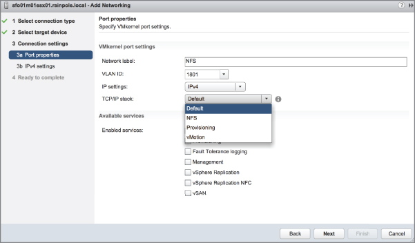
FIGURE 5.19 VMkernel ports can be assigned to a TCP/IP stack only at the time of creation.
CONFIGURING TCP/IP STACK SETTINGS
The settings for the TCP/IP stacks are found in the same place where you create and configure other host networking settings: in the Networking section of the Configure tab for an ESXi host object, as shown in Figure 5.20.

FIGURE 5.20 TCP/IP stack settings are located with other host networking configuration options.
In Figure 5.20, you can see the new TCP/IP stack, named NFS, that was created in the previous section. To edit the settings for that stack, select it from the list and click the Edit TCP/IP Stack Configuration icon (it looks like a pencil above the list of TCP/IP stacks). That brings up the Edit TCP/IP Stack Configuration dialog box, shown in Figure 5.21.

FIGURE 5.21 Each TCP/IP stack can have its own DNS configuration, routing information, and other advanced settings.
In the Edit TCP/IP Stack Configuration dialog box, make the changes you need to make to the name, DNS configuration, routing, or other advanced settings. Once you're finished, click OK.
It's now time to shift focus from host networking to virtual machine networking.
Configuring Virtual Machine Networking
The second type of port group to discuss is the Virtual Machine Port Group, which is responsible for all virtual machine networking. The Virtual Machine Port Group is quite different from a VMkernel port. With VMkernel networking, there is a one-to-one relationship with an interface: each VMkernel NIC, or vmknic, requires a matching VMkernel port group on a vSwitch. In addition, these interfaces require IP addresses for management or VMkernel network access.
A Virtual Machine Port Group, on the other hand, does not have a one-to-one relationship, and it does not require an IP address. For a moment, forget about vSwitches and consider standard physical switches. When you install or add an unmanaged physical switch into your network environment, that physical switch does not require an IP address; you simply install the switches and plug in the appropriate uplinks that will connect them to the rest of the network.
A vSwitch created with a Virtual Machine Port Group is no different. A vSwitch with a Virtual Machine Port Group acts just like an additional unmanaged physical switch. You need only plug in the appropriate uplinks—physical network adapters, in this case—that will connect that vSwitch to the rest of the network. As with an unmanaged physical switch, an IP address does not need to be configured for a Virtual Machine Port Group to combine the ports of a vSwitch with those of a physical switch. Figure 5.22 shows the switch-to-switch connection between a vSwitch and a physical switch.
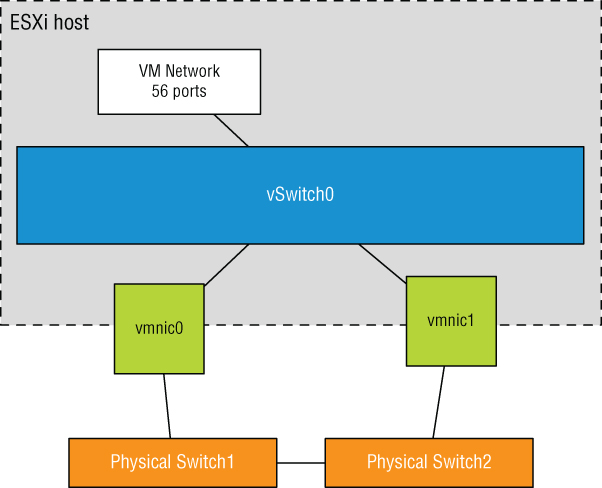
FIGURE 5.22 A vSwitch with a Virtual Machine Port Group uses associated physical network adapters to establish switch-to-switch connections with physical switches.
Perform the following steps to create a vSwitch with a Virtual Machine Port Group using the vSphere Web Client:
- Connect to a vCenter Server instance using the vSphere Web Client.
- From the Hosts And Clusters view, expand the vCenter Server tree.
- Select the ESXi host on which you'd like to add a vSwitch, click the Configure tab, and under Networking, click Virtual Switches.
- Click the Add Host Networking icon (a small globe with a plus sign) to start the Add Networking wizard.
- Select the Virtual Machine Port Group For A Standard Switch radio button and click Next.
- Because you are creating a new vSwitch, select the New Standard Switch radio button. Click Next.
- Click the green plus icon to add physical network adapters to the new vSwitch you are creating. From the Add Physical Adapters To The Switch dialog box, select the NIC or NICs that can carry the appropriate traffic for your virtual machines.
- Click OK when you're done selecting physical network adapters. This returns you to the Create A Standard Switch screen, where you can click Next to continue.
- Type the name of the Virtual Machine Port Group in the Network Label text box.
- Specify a VLAN ID, if necessary, and click Next.
- Click Next to review the virtual switch configuration, and then click Finish.
If you are a command-line junkie, you can create a Virtual Machine Port Group using PowerCLI as well.
Perform the following steps to create a vSwitch with a Virtual Machine Port Group using the command line:
- Open PowerCLI and connect to vCenter Server:
Connect-VIServer <vCenter host name> ↵When prompted to log in, enter the appropriate credentials.
- Enter the following command to add a virtual switch named vSwitch1 to the ESXi host sfo01m01esx01:
New-VirtualSwitch -VMhost sfo01m01esx01 -Name vSwitch1 ↵ - Enter the following command to add the physical NIC vmnic1 to vSwitch1:
Set-VirtualSwitch -VirtualSwitch vSwitch1 -Nic vmnic1 ↵By adding a physical NIC to the vSwitch, you provide physical network connectivity to the rest of the network for virtual machines connected to this vSwitch. Again, remember that you can assign any given physical NIC to only one vSwitch at a time (but a vSwitch may have multiple physical NICs at the same time).
- Enter the following command to create a Virtual Machine Port Group named ProductionLAN on vSwitch1:
New-VirtualPortGroup -VirtualSwitch vSwitch1 -Name ProductionLAN ↵
Of the different connection types—VMkernel ports and Virtual Machine Port Groups—vSphere administrators will spend most of their time creating, modifying, managing, and removing Virtual Machine Port Groups.
Configuring VLANs
A virtual LAN (VLAN) is a logical LAN that provides efficient segmentation, security, and broadcast control while allowing traffic to share the same physical LAN segments or same physical switches. Figure 5.23 shows a typical VLAN configuration across physical switches.
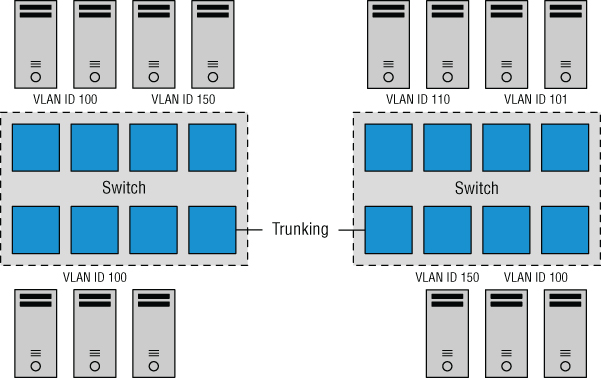
FIGURE 5.23 Virtual LANs provide secure traffic segmentation without the cost of additional hardware.
VLANs use the IEEE 802.1q standard for tagging traffic as belonging to a particular VLAN. The VLAN tag, also known as the VLAN ID, is a numeric value between 1 and 4094, and it uniquely identifies that VLAN across the network. Physical switches such as the ones depicted in Figure 5.23 must be configured with ports to trunk the VLANs across the switches. These ports are known as trunk ports. Ports not configured to trunk VLANs are known as access ports and can carry traffic only for a single VLAN at a time.
VLANs are an important part of ESXi networking because of the impact they have on the number of vSwitches and uplinks required. Consider this configuration:
- The management network needs access to the network segment carrying management traffic.
- Other VMkernel ports, depending on their purpose, may need access to an isolated vMotion segment or the network segment carrying iSCSI and NFS traffic.
- Virtual Machine Port Groups need access to whatever network segments are applicable for the virtual machines running on the ESXi hosts.
Without VLANs, this configuration would require three or more separate vSwitches, each bound to a different physical adapter, and each physical adapter would need to be physically connected to the correct network segment, as illustrated in Figure 5.24.

FIGURE 5.24 Supporting multiple networks without VLANs can increase the number of vSwitches, uplinks, and cabling that is required.
Add in an IP-based storage network and a few more virtual machine networks that need to be supported, and the number of required vSwitches and uplinks quickly grows. And this doesn't even take into account uplink redundancy.
VLANs are the answer to this dilemma. Figure 5.25 shows the same network as in Figure 5.24, but with VLANs this time.
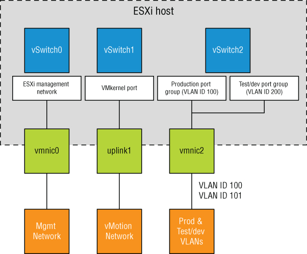
FIGURE 5.25 VLANs can reduce the number of vSwitches, uplinks, and cabling required.
Although the reduction from Figure 5.24 to Figure 5.25 is only a single vSwitch and a single uplink, you can easily add more virtual machine networks to the configuration in Figure 5.25 by simply adding another port group with another VLAN ID. Blade servers provide an excellent example of when VLANs offer tremendous benefit. Because of the small form factor of the blade casing, blade servers have historically offered limited expansion slots for physical network adapters. VLANs allow these blade servers to support more networks than they could otherwise.
As shown in Figure 5.25, VLANs are handled by configuring different port groups within a vSwitch. The relationship between VLANs and port groups is not a one-to-one relationship; a port group can be associated with only one VLAN at a time, but multiple port groups can be associated with a single VLAN. In the section “Configuring Virtual Switch Security,” later in this chapter, you'll see some examples of when you might have multiple port groups associated with a single VLAN.
To make VLANs work properly with a port group, the uplinks for that vSwitch must be connected to a physical switch port configured as a trunk port. A trunk port understands how to pass traffic from multiple VLANs simultaneously while also preserving the VLAN IDs on the traffic. Figure 5.26 shows a snippet of configuration from a Cisco Nexus 9000 series switch for a port configured as a trunk port.
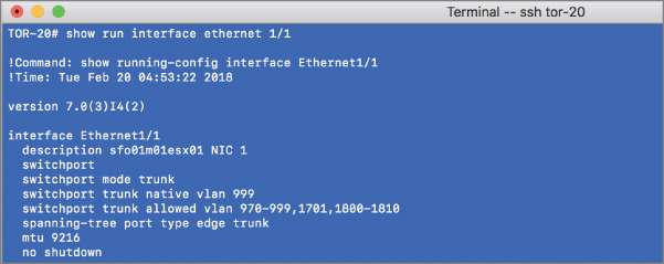
FIGURE 5.26 The physical switch ports must be configured as trunk ports in order to pass the VLAN information to the ESXi hosts for the port groups to use.
The configuration for switches from other manufacturers will vary, so be sure to check with your particular switch manufacturer for specific details on how to configure a trunk port.
When the physical switch ports are correctly configured as trunk ports, the physical switch passes the VLAN tags to the ESXi server, where the vSwitch directs the traffic to a port group with that VLAN ID assigned. If there is no port group configured with that VLAN ID, the traffic is discarded.
Perform the following steps to configure a Virtual Machine Port Group using VLAN ID 971:
- Connect to a vCenter Server instance using the vSphere Web Client.
- Navigate to the ESXi host to which you want to add the Virtual Machine Port Group, click the Configure tab, and then select Virtual Switches under Networking.
- Select the vSwitch where the new port group should be created.
- Click the Add Host Networking icon (it looks like a globe with a plus sign in the corner) to start the Add Networking wizard.
- Select the Virtual Machine Port Group For A Standard Switch radio button and click Next.
- Make sure the Select An Existing Standard Switch radio button is selected and, if necessary, use the Browse button to choose which virtual switch will host the new Virtual Machine Port Group. Click Next.
- Type the name of the Virtual Machine Port Group in the Network Label text box.
- Type 971 in the VLAN ID (Optional) text box, as shown in Figure 5.27.
You will want to substitute a value that is correct for your network.

FIGURE 5.27 You must specify the correct VLAN ID in order for a port group to receive traffic intended for a particular VLAN.
- Click Next to review the vSwitch configuration, and then click Finish.
As you've probably gathered by now, you can also use PowerCLI to create or modify the VLAN settings for ports or port groups. We won't go through the steps here because the commands are extremely similar to what we've shown you already.
Although VLANs reduce the costs of constructing multiple logical subnets, keep in mind that they do not address traffic constraints. Although VLANs logically separate network segments, all the traffic still runs on the same physical network underneath. To accommodate bandwidth-intensive network operations, ensure the physical network adapters and switches are capable of sustaining the required throughput.
Configuring NIC Teaming
For a vSwitch and its associated ports or port groups to communicate with other ESXi hosts or with physical systems, the vSwitch must have at least one uplink. An uplink is a physical network adapter that is bound to the vSwitch and connected to a physical network switch. With the uplink connected to the physical network, there is connectivity for the VMkernel and the virtual machines connected to that vSwitch. But what happens when that physical network adapter fails, when the cable connecting that uplink to the physical network fails, or the upstream physical switch to which that uplink is connected fails? With a single uplink, network connectivity to the entire vSwitch and all of its ports or port groups is lost. This is where NIC teaming comes in.
NIC teaming involves connecting multiple physical network adapters to a single vSwitch. NIC teaming provides redundancy and load balancing of network communications to the VMkernel and virtual machines.
Figure 5.28 illustrates NIC teaming conceptually. Both of the vSwitches have two uplinks, and each of the uplinks connect to a different physical switch. Note that NIC teaming supports all the different connection types, so it can be used with ESXi management networking, VMkernel networking, and networking for virtual machines.
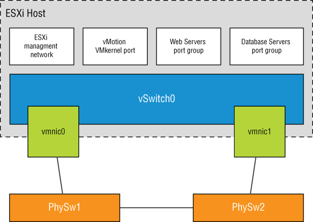
FIGURE 5.28 Virtual switches with multiple uplinks offer redundancy and load balancing.
Figure 5.29 shows what NIC teaming looks like from within the vSphere Web Client. In this example, the vSwitch is configured with an association to multiple physical network adapters (uplinks). As mentioned previously, the ESXi host can have a maximum of 32 uplinks; these uplinks can be spread across multiple vSwitches or all tossed into a NIC team on one vSwitch. Remember that you can connect a physical NIC to only one vSwitch at a time.

FIGURE 5.29 The vSphere Web Client shows when multiple physical network adapters are associated with a vSwitch using NIC teaming.
Building a functional NIC team requires that all uplinks be connected to physical switches in the same broadcast domain. If VLANs are used, all the switches should be configured for VLAN trunking, and the appropriate subset of VLANs must be allowed across the VLAN trunk. In a Cisco switch, this is typically controlled with the switchport trunk allowed vlan statement.
In Figure 5.30, the NIC team for vSwitch0 will work, because both of the physical switches share VLAN 100. The NIC team for vSwitch1, however, will not work because the physical switches the network adapters are connected to do not carry the same VLAN's, in this case VLAN 200.

FIGURE 5.30 All the physical network adapters in a NIC team must carry the same VLANs.
Perform the following steps to create a NIC team with an existing vSwitch using the vSphere Web Client:
- Connect to a vCenter Server instance using the vSphere Web Client.
- Navigate to the Networking section of the Configure tab for the ESXi host where you want to create the NIC team.
- Select Virtual Switches; then select the virtual switch that will be assigned a NIC team and click the Manage The Physical Adapters Connected To The Selected Virtual Switch icon (it looks like a NIC with a wrench).
- In the Manage Physical Network Adapters dialog box, click the green Add Adapters icon.
- In the Add Physical Adapters To The Switch dialog box, select the appropriate adapter (or adapters) from the list, as shown in Figure 5.31.
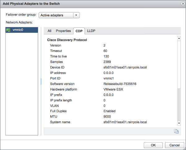
FIGURE 5.31 Create a NIC team by adding network adapters that belong to the same layer 2 broadcast domain as the original adapter.
- Click OK to return to the Manage Physical Network Adapters dialog box.
- Click OK to complete the process and return to the Virtual Switch section of the selected ESXi host. Note that it might take a moment or two for the display to update with the new physical adapter.
After a NIC team is established for a vSwitch, ESXi can then perform load balancing for that vSwitch. The load-balancing feature of NIC teaming does not function like the load-balancing feature of advanced routing protocols. Load balancing across a NIC team is not a product of identifying the amount of traffic transmitted through a network adapter and shifting traffic to equalize data flow through all available adapters. The load-balancing algorithm for NIC teams in a vSwitch is a balance of the number of connections—not the amount of traffic. NIC teams on a vSwitch can be configured with one of the following four load-balancing policies:
- Originating virtual port-based load balancing (default)
- Source MAC-based load balancing
- IP hash-based load balancing
- Explicit failover order
The last option, explicit failover order, isn't really a “load-balancing” policy; instead, it uses the administrator-assigned failover order whereby the highest order uplink from the list of active adapters that passes failover detection criteria is used. You'll learn more about failover order in the section “Configuring Failover Detection and Failover Policy,” later in this chapter. Also note that the list I've supplied here applies only to vSphere Standard Switches; vSphere Distributed Switches, covered later in this chapter in the section “Working with vSphere Distributed Switches,” have additional options for load balancing and failover.
- NOTE The load-balancing feature of NIC teams on a vSwitch applies only to the outbound traffic.
REVIEWING ORIGINATION VIRTUAL PORT-BASED LOAD BALANCING
The default load-balancing policy route is based on the originating virtual port and uses an algorithm that ties (or pins) each virtual switch port to a specific uplink associated with the vSwitch. The algorithm attempts to maintain an equal number of port-to-uplink assignments across all uplinks to achieve load balancing. As shown in Figure 5.32, this policy setting ensures that traffic from a specific virtual network adapter connected to a virtual switch port will consistently use the same physical network adapter. In the event that one of the uplinks fails, the traffic from the failed uplink will fail over to another physical network adapter.
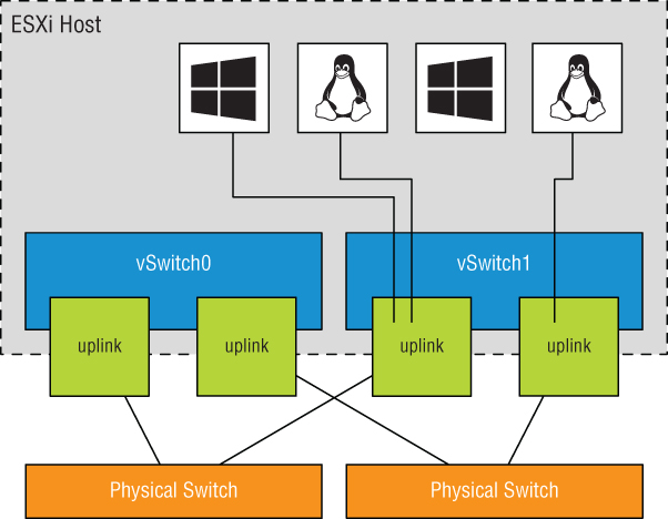
FIGURE 5.32 The virtual port-based load balancing policy assigns each virtual switch port to a specific uplink. Failover to another uplink occurs when one of the physical network adapters experiences failure.
Although this policy does not provide dynamic load balancing, it does provide redundancy. Because the port for a virtual machine does not change, each virtual machine is tied to a physical network adapter until failover or vMotion occurs regardless of the amount of network traffic. Looking at Figure 5.32, imagine that the Linux virtual machine and the Windows virtual machine on the far left are the two most network intensive virtual machines. In this case, the virtual port-based policy has assigned both ports for these virtual machines to the same physical network adapter. In this case, one physical network adapter could be much more heavily used than other network adapters in the NIC team.
The physical switch passing the traffic learns the port association and therefore sends replies back through the same physical network adapter from which the request initiated. The virtual port-based policy is best used when you have more virtual network adapters than physical network adapters, which is almost always the case for virtual machine traffic. When there are fewer virtual network adapters, some physical adapters will not be used. For example, if five virtual machines are connected to a vSwitch with six uplinks, only five vSwitch ports will be assigned to exactly five uplinks, leaving one uplink with no traffic to process.
REVIEWING SOURCE MAC-BASED LOAD BALANCING
The second load-balancing policy available for a NIC team is the source MAC-based policy, shown in Figure 5.33. This policy is susceptible to the same pitfalls as the virtual port-based policy simply because the static nature of the source MAC address is the same as the static nature of a virtual port assignment. The source MAC-based policy is also best used when you have more virtual network adapters than physical network adapters. In addition, virtual machines still cannot use multiple physical adapters unless configured with multiple virtual network adapters. Multiple virtual network adapters inside the guest OS of a virtual machine will provide multiple source MAC addresses and allow multiple physical network adapters.

FIGURE 5.33 The source MAC-based load balancing policy, as the name suggests, ties a virtual network adapter to a physical network adapter based on the MAC address.
REVIEWING IP HASH-BASED LOAD BALANCING
The third load-balancing policy available for NIC teams is the IP hash-based policy, also called the out-IP policy. This policy, shown in Figure 5.34, addresses the static-like limitation of the other two policies. The IP hash-based policy uses the source and destination IP addresses to calculate a hash. The hash determines the physical network adapter to use for communication. Different combinations of source and destination IP addresses will, quite naturally, produce different hashes. Based on the hash, then, this algorithm could allow a single virtual machine to communicate over different physical network adapters when communicating with different destinations, assuming that the calculated hashes select a different physical NIC.

FIGURE 5.34 The IP hash-based policy is a more scalable load-balancing policy that allows virtual machines to use more than one physical network adapter when communicating with multiple destination hosts.
The vSwitch with the NIC-teaming load-balancing policy set to use the IP-based hash must have all physical network adapters connected to the same physical switch or switch stack. In addition, the switch must be configured for link aggregation. ESXi configured to use a vSphere Standard Switch supports standard 802.3ad link aggregation in static (manual) mode, sometimes referred to as EtherChannel, but does not support dynamic-mode link-aggregation protocols such as LACP. Link aggregation may increase overall aggregate throughput by potentially combining the bandwidth of multiple physical network adapters for use by a single virtual network adapter of a virtual machine.
Also consider when using the IP hash-based load-balancing policy that all physical NICs must be set to active. This is because of the way IP hash-based load balancing works between the virtual switch and the physical switch.
Perform the following steps to alter the NIC-teaming load-balancing policy of a vSwitch:
- Connect to a vCenter Server instance using the vSphere Web Client.
- Navigate to the specific ESXi host that has the vSwitch whose NIC teaming configuration you wish to modify.
- With an ESXi host selected, go to the Configure tab and select Virtual Switches.
- Select the name of the virtual switch from the list of virtual switches, and then click the Edit icon (it looks like a pencil).
- In the Edit Settings dialog box, select Teaming And Failover, and then select the desired load-balancing setting from the Load Balancing drop-down list, as shown in Figure 5.35.

FIGURE 5.35 Select the load-balancing policy for a vSwitch in the Teaming And Failover section.
- Click OK to save the changes.
Now that we've explained the load-balancing policies, and before we explain explicit failover order, let's take a deeper look at the failover and failback of uplinks in a NIC team. There are two parts to consider: failover detection and failover policy. We'll cover both of these in the next section.
CONFIGURING FAILOVER DETECTION AND FAILOVER POLICY
Failover detection with NIC teaming can be configured to use either a link status method or a beacon probing method.
The link status failover detection method works just as the name suggests. The link status of the physical network adapter identifies the failure of an uplink. In this case, failure is identified for events like removed cables or power failures on a physical switch. The downside to the setting for link status failover detection is its inability to identify misconfigurations or pulled cables that connect the switch to other networking devices (for example, a cable connecting one switch to an upstream switch).
The beacon probing failover detection setting, which includes link status as well, sends Ethernet broadcast frames across all physical network adapters in the NIC team. These broadcast frames allow the vSwitch to detect upstream network connection failures and will force failover when STP blocks ports, when ports are configured with the wrong VLAN, or when a switch-to-switch connection has failed. When a beacon is not returned on a physical network adapter, the vSwitch triggers the failover notice and reroutes the traffic from the failed network adapter through another available network adapter based on the failover policy.
Consider a vSwitch with a NIC team consisting of three physical network adapters, where each adapter is connected to a different physical switch, each of which is connected to an upstream switch as shown in Figure 5.36. When the NIC team is set to the beacon-probing failover-detection method, a beacon will be sent out over all three uplinks.

FIGURE 5.36 The beacon-probing failover-detection policy sends beacons out across the physical network adapters of a NIC team to identify upstream network failures or switch misconfigurations.
After a failure is detected, either via link status or beacon probing, a failover will occur. Traffic from any virtual machines or VMkernel ports is rerouted to another member of the NIC team. Exactly which member that might be, though, depends primarily on the configured failover order.
Figure 5.37 shows the failover order configuration for a vSwitch with two adapters in a NIC team. In this configuration, both adapters are configured as active adapters, and either adapter or both adapters may be used at any given time to handle traffic for this vSwitch and all its associated ports or port groups.

FIGURE 5.37 The failover order helps determine how adapters in a NIC team are used when a failover occurs.
Now look at Figure 5.38. This figure shows a vSwitch with three physical network adapters in a NIC team. In this configuration, one of the adapters is configured as a standby adapter. Any adapters listed as standby adapters will not be used until a failure occurs on one of the active adapters, at which time the standby adapters activate in the order listed.
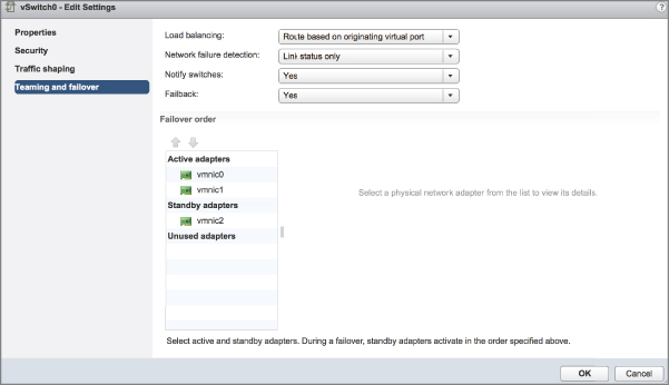
FIGURE 5.38 Standby adapters automatically activate when an active adapter fails.
It should go without saying, but adapters that are listed in the Unused Adapters section will not be used in the event of a failure.
Now take a quick look back at Figure 5.35. You'll see an option there labeled Use Explicit Failover Order. This is the explicit failover order policy mentioned toward the beginning of the earlier section “Configuring NIC Teaming.” If you select that option instead of one of the other load-balancing options, traffic will move to the next available uplink in the list of active adapters. If no active adapters are available, traffic will move down the list to the standby adapters. Just as the name of the option implies, ESXi will use the order of the adapters in the failover order to determine how traffic will be placed on the physical network adapters. Because this option does not perform any sort of load balancing whatsoever, it's generally not recommended and one of the other options is used instead.
The Failback option controls how ESXi will handle a failed network adapter when it recovers from failure. The default setting, Yes, as shown in Figure 5.37 and Figure 5.38, indicates that the adapter will be returned to active duty immediately upon recovery, and it will replace any standby adapter that may have taken its place during the failure. Setting Failback to No means that the recovered adapter remains inactive until another adapter fails, triggering the replacement of the newly failed adapter.
Perform the following steps to configure the Failover Order policy for a NIC team:
- Connect to a vCenter Server instance using the vSphere Web Client.
- Navigate to the ESXi host that has the vSwitch for which you'd like to change the failover order. With an ESXi host selected, select the Configure tab and click Virtual Switches.
- Select the virtual switch you want to edit and click the Edit Settings icon.
- Select Teaming And Failover.
- Use the Move Up and Move Down buttons to adjust the order of the network adapters and their location within the Active Adapters, Standby Adapters, and Unused Adapters lists, as shown in Figure 5.39.

FIGURE 5.39 Failover order for a NIC team is determined by the order of network adapters as listed in the Active Adapters, Standby Adapters, and Unused Adapters lists.
- Click OK to save the changes.
When a failover event occurs on a vSwitch with a NIC team, the vSwitch is obviously aware of the event. The physical switch that the vSwitch is connected to, however, will not know immediately. As you can see in Figure 5.39, a vSwitch includes a Notify Switches configuration setting, which, when set to Yes, will allow the physical switch to immediately learn of any of the following changes:
- A virtual machine is powered on (or any other time a client registers itself with the vSwitch).
- A vMotion occurs.
- A MAC address is changed.
- A NIC team failover or failback has occurred.
In any of these events, the physical switch is notified of the change using the Reverse Address Resolution Protocol (RARP). RARP updates the lookup tables on the physical switches and offers the shortest latency when a failover event occurs.
Although the VMkernel works proactively to keep traffic flowing from the virtual networking components to the physical networking components, VMware recommends taking the following actions to minimize networking delays:
- Disable PAgP and LACP on the physical switches.
- Disable DTP or trunk negotiation.
- Disable STP.
Using and Configuring Traffic Shaping
By default, all virtual network adapters connected to a vSwitch have access to the full amount of bandwidth on the physical network adapter with which the vSwitch is associated. In other words, if a vSwitch is assigned a 10 Gbps network adapter, each virtual machine configured to use the vSwitch has access to 10 Gbps of bandwidth. Naturally, if contention becomes a bottleneck hindering virtual machine performance, NIC teaming will help. However, as a complement to NIC teaming, you can also enable and configure traffic shaping. Traffic shaping establishes hard-coded limits for peak bandwidth, average bandwidth, and burst size to reduce a virtual machines outbound bandwidth capability.
As shown in Figure 5.40, the Peak Bandwidth value and the Average Bandwidth value are specified in kilobits per second, and the Burst Size value is configured in units of kilobytes. The value entered for Average Bandwidth dictates the data transfer per second across the virtual switch. The Peak Bandwidth value identifies the maximum amount of bandwidth a vSwitch can pass without dropping packets. Finally, the Burst Size value defines the maximum amount of data included in a burst. The burst size is a calculation of bandwidth multiplied by time. During periods of high utilization, if a burst exceeds the configured value, packets are dropped in favor of other traffic; however, if the queue for network traffic processing is not full, the packets are retained for transmission at a later time.

FIGURE 5.40 Traffic shaping reduces the outbound (or egress) bandwidth available to a port group.
Perform the following steps to configure traffic shaping:
- Connect to a vCenter Server instance using the vSphere Web Client.
- Navigate to the ESXi host on which you'd like to configure traffic shaping. With an ESXi host selected, go to the Virtual Switch section of the Configure tab.
- Select the virtual switch where you want to enable traffic shaping, and then click the Edit Settings icon.
- Select Traffic Shaping.
- Select the Enabled option from the Status drop-down list.
- Adjust the Average Bandwidth value to the desired number of kilobits per second.
- Adjust the Peak Bandwidth value to the desired number of kilobits per second.
- Adjust the Burst Size value to the desired number of kilobytes.
Keep in mind that traffic shaping on a vSphere Standard Switch applies only to outbound (or egress) traffic.
Bringing It All Together
By now, you've seen how all the various components of ESXi virtual networking interact with each other, vSwitches, ports and port groups, uplinks and NIC teams, and VLANs. But how do you assemble all these pieces into a usable whole?
The number and the configuration of the vSwitches and port groups depend on several factors, including the number of network adapters in the ESXi host, the number of IP subnets, the existence of VLANs, and the number of physical networks. With respect to the configuration of the vSwitches and Virtual Machine Port Groups, no single correct configuration will satisfy every scenario. However, the greater the number of physical network adapters in an ESXi host, the more flexibility you will have in your virtual networking architecture.
Later in the chapter, we'll discuss some advanced design factors, but for now, let's stick with some basic design considerations. If the vSwitches will not be configured with VLANs, you must create a separate vSwitch for every IP subnet or physical network to which you need to connect. This was illustrated previously in Figure 5.24 in our discussion about VLANs. To understand this concept, let's look at two more examples.
Figure 5.41 shows a scenario with five IP subnets that your virtual infrastructure components need to reach. The virtual machines in the production environment must reach the production LAN, the virtual machines in the test environment must reach the test LAN, the VMkernel needs to access the IP storage and vMotion LANs, and finally, the ESXi host must have access to the management LAN. In this scenario, without VLANs and port groups, the ESXi host must have five different vSwitches and five different physical network adapters. (Of course, this doesn't account for redundancy or NIC teaming for the vSwitches.)

FIGURE 5.41 Without VLANs, each IP subnet will require a separate vSwitch with the appropriate connection type.
Figure 5.42 shows the same configuration, but this time using VLANs for the Management, vMotion, Production, and Test/Dev networks. The IP storage network is still a physically separate network (a common configuration for iSCSI in many environments).
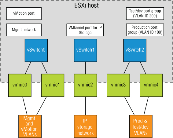
FIGURE 5.42 The use of the physically separate IP storage network limits the reduction in the number of vSwitches and uplinks.
The configuration in Figure 5.42 still uses three network adapters, but this time you're able to provide NIC teaming for all the networks.
If the IP storage network were configured as a VLAN, the number of vSwitches and uplinks could be further reduced. Figure 5.43 shows a possible configuration that would support this sort of scenario.

FIGURE 5.43 With the use of port groups and VLANs in the vSwitches, even fewer vSwitches and uplinks are required.
This time, you're able to provide NIC teaming to all the traffic types involved—Management, vMotion, IP storage, and virtual machine traffic—using only a single vSwitch with multiple uplinks.
Clearly, there is a tremendous amount of flexibility in how vSwitches, uplinks, and port groups are assembled to create a virtual network capable of supporting your infrastructure. Even given all this flexibility, though, there are limits. Table 5.1 lists some of the limits of ESXi networking.
With all the flexibility provided by the different vSphere networking components, you can be assured that whatever the physical network configuration might hold in store, there are several ways to integrate the vSphere networking. What you configure today may change as the infrastructure changes or as the hardware changes. ESXi provides enough tools and options to ensure a successful communication scheme between the vSphere and physical networks.
Working with vSphere Distributed Switches
So far, our discussion has focused solely on vSphere Standard Switches (just vSwitches). Starting with vSphere 4.0 and continuing with the current release, there is another option: vSphere Distributed Switches.
Whereas vSphere Standard Switches are managed per host, a vSphere Distributed Switch functions as a single virtual switch across all the associated ESXi hosts within a datacenter object. There are a number of similarities between a vSphere Distributed Switch and a Standard Switch:
- A vSphere Distributed Switch provides connectivity for virtual machines and VMkernel interfaces.
- A vSphere Distributed Switch leverages physical network adapters as uplinks to provide connectivity to the external physical network.
- A vSphere Distributed Switch can leverage VLANs for logical network segmentation.
- Most of the same load balancing, failback, security, and traffic shaping policies are available, with a few additions in the vSphere Distributed Switch that increase functionality over the vSphere Standard Switch.
Of course, differences exist as well, but the most significant of these is that a vSphere Distributed Switch can span multiple hosts in a vSphere Datacenter instead of each host having its own set of independent vSwitches and port groups. This greatly reduces complexity in clustered ESXi environments and simplifies the addition of new servers to an ESXi cluster.
VMware's official abbreviation for a vSphere Distributed Switch is VDS. In this chapter, we'll use the full name (vSphere Distributed Switch), VDS, or sometimes just distributed switch to refer to this feature.
Creating a vSphere Distributed Switch
The process of creating and configuring a distributed switch is twofold. First, you create the distributed switch at the datacenter object level, and then you add ESXi hosts to it.
Perform the following steps to create a new vSphere Distributed Switch:
- Launch the vSphere Web Client and connect to a vCenter Server instance.
- On the vSphere Web Client home screen, select Networking from the Navigator.
- Right-click the datacenter object, navigate to Distributed Switch, and select New Distributed Switch.
This launches the New Distributed Switch wizard.
- Supply a name for the new Distributed Switch and click Next.
- Select the version of the Distributed Switch you'd like to create. Figure 5.44 shows the options for distributed switch versions.

FIGURE 5.44 If you want to support all the features included in vSphere 6.7, you must use a version 6.6.0 distributed switch.
Six options are available:
- Distributed Switch 5.0.0: This version is compatible only with vSphere 5.0 and later and adds support for features such as user-defined network resource pools in Network I/O Control, NetFlow, and port mirroring.
- Distributed Switch 5.1.0: Compatible with vSphere 5.1 or later, this version of the Distributed Switch adds support for Network Rollback and Recovery, Health Check, Enhanced Port Mirroring, and LACP.
- Distributed Switch 5.5.0: This version is supported on vSphere 5.5 or later. This Distributed Switch adds traffic filtering and marking and enhanced support for LACP.
- Distributed Switch 6.0.0: This version is supported on vSphere 6.0 or later. This version of the Distributed Switch adds NIOC3 support, multicast snooping, and multicast filtering.
- Distributed Switch 6.5.0: This version is supported on vSphere 6.5 or later. This version of the Distributed Switch supports the ERSPAN port-mirroring protocol.
- Distributed Switch 6.6.0: This is the latest version and is only supported on vSphere 6.7. This version of the Distributed Switch supports MAC Learning.
In this case, select vSphere Distributed Switch Version 6.6.0 and click Next.
- Specify the number of uplink ports, as illustrated in Figure 5.45.

FIGURE 5.45 The number of uplinks controls how many physical adapters from each host can serve as uplinks for the distributed switch.
- On the same screen shown in Figure 5.45, select whether you want Network I/O Control enabled or disabled. Also specify whether you want to create a default port group and, if so, what the name of that default port group should be. For this example, leave Network I/O Control enabled, and create a default port group with the name of your choosing. Click Next.
- Review the settings for your new distributed switch. If everything looks correct, click Finish; otherwise, use the Back button to go back and change settings as needed.
After you complete the New Distributed Switch wizard, a new distributed switch will appear in the vSphere Web Client. You can click the new distributed switch to see the ESXi hosts connected to it (none yet), the virtual machines hosted on it (none yet), the distributed ports groups on (only one—the one you created during the wizard), and the uplink port groups (of which there is also only one).
All this information is also available using the vSphere CLI or PowerCLI, but due to the nature of how the esxcli command is structured, you'll need to have an ESXi host added to the distributed switch first. Let's look at how that's done.
Once you've created a distributed switch, it is relatively easy to add an ESXi host. When the ESXi host is added, all of the distributed port groups will automatically be propagated to the host with the correct configuration. This is the distributed nature of the distributed switch, as configuration changes are made via the vSphere Web Client, vCenter Server pushes those changes out to all participating ESXi hosts. VMware administrators who are used to managing large ESXi clusters and having to repeatedly create vSwitches and port groups and maintain consistency of these port groups across hosts will be pleased with the reduction in administrative overhead that distributed switches offer.
Perform the following steps to add an ESXi host to an existing distributed switch:
- Launch the vSphere Web Client and connect to a vCenter Server instance.
- In the Navigator, click Networking.
- Select an existing distributed switch, and then select Add And Manage Hosts from the Actions menu.
This launches the Add And Manage Hosts wizard, shown in Figure 5.46.
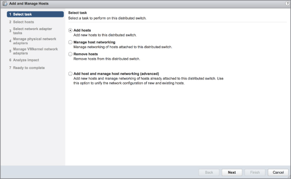
FIGURE 5.46 When you're working with distributed switches, the vSphere Web Client offers a single wizard to add hosts, remove hosts, or manage host networking.
- Select the Add Hosts radio button and click Next.
- Click the green plus icon to add an ESXi host. This opens the Select New Host dialog box.
- From the list of new hosts to add, place a check mark next to the name of each ESXi host you'd like to add to the distributed switch. Click OK when you're done, and then click Next to continue.
- The next screen offers three different adapter-related tasks to perform, as shown in Figure 5.47. In this case, make sure only Manage Physical Adapters is selected. Click Next to continue.
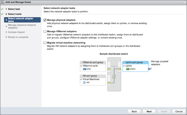
FIGURE 5.47 All adapter-related changes to distributed switches are consolidated into a single wizard.
The Manage VMkernel Adapters option allows you to add, migrate, edit, or remove VMkernel adapters (VMkernel ports) from this distributed switch.
The Migrate Virtual Machine Networking option enables you to migrate virtual machine network adapters to this distributed switch.
- The next screen lets you choose the physical adapters on the hosts that should be connected to the uplinks port group for the distributed switch. For each physical adapter you'd like to add, click the adapter and then click Assign Uplink. You'll be prompted to confirm the uplink to which this physical adapter should be connected. Repeat this process to add as many physical adapters as you have uplinks configured for the distributed switch.
- NOTE Leave at least one physical adapter connected to your vSphere Standard Switch until you have migrated the management VMkernel port. If you attempt to move them all at this point, the operation will fail because there will be no connectivity to the ESXi hosts.
- Repeat step 8 for each ESXi host you're adding to the distributed switch. Click Next when you're finished adding uplinks for all ESXi hosts.
- The Analyze Impact screen displays the potential effects of the changes proposed by the wizard. If everything looks okay, click Next; otherwise, click Back to go back and change the settings.
- Click Finish to complete the wizard.
You'll have an opportunity to see this wizard again in later sections. For example, we'll discuss the options for managing physical and VMkernel adapters in more detail in the section “Managing VMkernel Adapters,” later in this chapter.
We mentioned earlier in this section that you could use the vSphere CLI to see distributed switch information after you'd added a host to the distributed switch. The following command will show you a list of the distributed switches that a particular ESXi host is a member of:
esxcli network vswitch dvs vmware list The output will look similar to the output shown in Figure 5.48.
![esxcli command displaying codes [root@sfo01m01es01:~] esxcli network vswitch dvs vmware list, sfo01-m01-vds01, Name: sfo01-m01-vds01, VDS ID: 50 17 9f 05 85 25 c1 b2-72 ff 3d 47 2e 43 09 bb, Class: cswitch, etc.](http://images-20200215.ebookreading.net/2/2/2/9781119512943/9781119512943__mastering-vmware-vsphere__9781119512943__images__c05f048.jpg)
FIGURE 5.48 The esxcli command shows full details on the configuration of a distributed switch.
Use the --help parameter with the network vswitch dvs vmware namespace command to see some of the other tasks that you can perform with the vSphere CLI related to vSphere Distributed Switches.
Now, let's take a look at a few other tasks related to distributed switches. We'll start with removing an ESXi host from a distributed switch.
Removing an ESXi Host from a Distributed Switch
Naturally, you can also remove ESXi hosts from a distributed switch. You can't remove a host from a distributed switch if it still has virtual machines connected to a distributed port group on that switch. This is analogous to trying to delete a standard switch or a port group while a virtual machine is still connected; this, too, is prevented. To allow the ESXi host to be removed from the distributed switch, you must move all virtual machines to a standard switch or a different distributed switch.
Perform the following steps to remove an individual ESXi host from a distributed switch:
- Launch the vSphere Web Client and connect to a vCenter Server instance.
- Navigate to the list of distributed switches and select the specific distributed switch from which you'd like to remove an individual ESXi host.
- From the Actions menu, select Add And Manage Hosts. This will bring up the Add And Manage Hosts dialog box, shown earlier in Figure 5.47.
- Select the Remove Hosts radio button. Click Next.
- Click the green plus icon to select hosts to be removed from the distributed switch.
- In the Select Member Hosts dialog box, place a check mark next to each ESXi host you'd like to remove from the distributed switch. Click OK when you're done selecting hosts.
- Click Finish to remove the selected ESXi hosts.
- If any virtual machines are still connected to the distributed switch, the vSphere Web Client will display an error similar to the one shown in Figure 5.49.
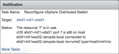
FIGURE 5.49 The vSphere Web Client won't allow a host to be removed from a distributed switch if a virtual machine is still attached.
To correct this error, reconfigure the virtual machine(s) to use a different distributed switch or standard switch. Then proceed with removing the host from the distributed switch.
If there were no virtual machines attached to the distributed switch, or after all virtual machines are reconfigured to use a different standard switch or distributed switch, the host is removed.
In addition to removing individual ESXi hosts from a distributed switch, you can remove the entire distributed switch.
Removing a Distributed Switch
Removing the last ESXi host from a distributed switch does not remove the distributed switch itself. Even if all the virtual machines and/or ESXi hosts have been removed from the distributed switch, the distributed switch still exists in the vCenter inventory. You must still remove the distributed switch object itself.
You can only remove a distributed switch when no virtual machines are assigned to a distributed port group on the distributed switch. Otherwise, the removal is blocked with an error message similar to the one shown earlier in Figure 5.49. Again, you'll need to reconfigure the virtual machine(s) to use a different standard switch or distributed switch before the operation can proceed. Refer to Chapter 9, “Creating and Managing Virtual Machines,” for more information on modifying a virtual machine's network settings.
Follow these steps to remove the distributed switch if no virtual machines are connected to any distributed port group on it:
- Launch the vSphere Web Client and connect to a vCenter Server instance.
- From the Navigator, select Networking.
- Select an existing vSphere Distributed Switch.
- From the Actions menu, select Delete.
The distributed switch and all associated distributed port groups are removed from the inventory and from any connected hosts.
The bulk of the configuration for a distributed switch isn't performed for the distributed switch itself but rather for the distributed port groups on that distributed switch. Nevertheless, let's first take a look at managing distributed switches themselves.
Managing Distributed Switches
As stated earlier, the vast majority of tasks a VMware administrator performs with a distributed switch involve working with distributed port groups. We'll explore distributed port groups later, but for now, let's discuss managing the distributed switch.
The Configure tab is an area you've already seen and will see again throughout this chapter; in particular, you've been working in the Settings section of the Configure tab quite a bit. You'll continue to do so as you start creating distributed port groups. The Configure tab also includes the Resource Allocation section.
The Resource Allocation section is where you'll allocate resources for system traffic and create network resource pools for use with Network I/O Control, a topic discussed in Chapter 11, “Managing Resource Allocation.”
On the Monitor tab, there are three sections:
- The Issues section shows issues and/or alarms pertaining to a distributed switch.
- The Tasks and Events sections provide insight into recently performed tasks and a list of events that have occurred and could be the result of either user or system action. You could use these sections to see which user performed a certain task or to review various events pertaining to the selected distributed switch.
- The Health section centralizes health information for the distributed switch, such as VLAN checks, MTU checks, and other health checks.
The Health section contains some rather important functionality, so let's dig a little deeper into that section in particular.
USING HEALTH CHECKS AND NETWORK ROLLBACK
The vSphere Distributed Switch Health Check feature was added in vSphere 5.1 and is available only when you're using a version 5.1.0 or above distributed switch. The idea behind the health check feature is to help VMware administrators identify mismatched VLAN configurations, mismatched MTU configurations, and mismatched NIC teaming policies, all of which are common sources of connectivity issues.
You should know the requirements for using the health check feature:
- You must be using a version 5.1.0 or above distributed switch.
- VLAN and MTU checks require at least two NICs with active links.
- The teaming policy check requires at least two NICs with active links and at least two hosts.
By default, vSphere Distributed Switch Health Check is turned off; you must enable it in order to perform checks.
To enable vSphere Distributed Switch Health Check, perform these steps:
- Connect to a vCenter Server instance using the vSphere Web Client.
- From the Navigator, select Networking and select the distributed switch you wish to enable the Health Check feature on.
- Click the Configure tab and then select Health Check.
- Click the Edit button.
- In the Edit Health Check Settings dialog box, you can independently enable checks for VLAN and MTU, teaming and failover, or both. Click OK when finished.
After the health checks are enabled, you can view the health check information on the Monitor tab of the distributed switch. Figure 5.50 shows the health check information for a distributed switch once health checks have been enabled.
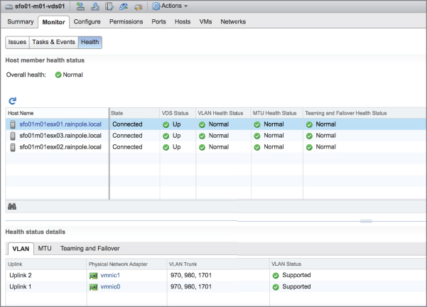
FIGURE 5.50 The vSphere Distributed Switch Health Check helps identify potential problems in configuration.
Closely related to the health check functionality is a feature called vSphere Network Rollback. The idea behind network rollback is to automatically protect environments against changes that would disconnect ESXi hosts from vCenter Server by rolling back changes if they are invalid. For example, changes to the speed or duplex of a physical NIC, updating teaming and failover policies for a switch that contains the ESXi host's management interface, or changing the IP settings of a host's management interface are all examples of changes that are validated when they occur. If the change would result in a loss of management connectivity to the host, the change is reverted, or rolled back, automatically.
Rollbacks can occur at two levels: at the host networking level or distributed switch level. Rollback is enabled by default.
In addition to automatic rollbacks, VMware administrators have the option of performing manual rollbacks. You learned how to do a manual rollback at the host level earlier, in the section “Configuring the Management Network,” which discussed the Network Restore Options area of an ESXi host's DCUI. To perform a manual rollback of a distributed switch, you use the same process as restoring from a saved configuration, which will be discussed in the next section.
IMPORTING AND EXPORTING DISTRIBUTED SWITCH CONFIGURATION
vSphere 5.1 added the ability to export (save) and import (load) the configuration of a distributed switch. This functionality can serve a number of purposes; one purpose is to manually “roll back” to a previously saved configuration.
To export (save) the configuration of a distributed switch to a file, perform these steps:
- Log into a vCenter Server instance using the vSphere Web Client.
- Navigate to the distributed switch whose configuration you'd like to save.
- From the Actions menu, select Settings ⇒ Export Configuration. This opens the Export Configuration dialog box.
- Select the appropriate radio button to export either the configuration of the distributed switch and all the distributed ports groups or just the configuration of the distributed switch.
- Optionally, supply a description of the exported (saved) configuration; then click OK.
- When prompted to specify whether you want to save the exported configuration file, click Yes.
- Use your operating system's File Save dialog box to select the location where the exported configuration file (named
backup.zip) should be saved.
Once you have the configuration exported to a file, you can then import this configuration back into your vSphere environment at a later date to restore the saved configuration. You can also import the configuration into a different vSphere environment, such as an environment being managed by a separate vCenter Server instance.
To import a saved configuration, perform these steps:
- Log into a vCenter Server instance using the vSphere Web Client.
- Navigate to the distributed switch whose configuration you'd like to restore.
- From the Actions menu, select Settings ⇒ Restore Configuration. This opens the Restore Configuration wizard.
- Use the Browse button to select the saved configuration file created earlier by exporting the configuration.
- Select the appropriate radio button to restore either the distributed switch and all distributed port groups or just the distributed switch configuration.
- Click Next.
- Review the settings that the wizard will import. If everything is correct, click Finish; otherwise, click Back to go back and make changes.
Both vSphere Network Rollback and the ability to manually export or import the configuration of a distributed switch are major steps forward in managing distributed switches in a vSphere environment.
Most of the work that a VMware administrator needs to perform will revolve around distributed port groups, so let's turn our attention to working with them.
Working with Distributed Port Groups
With vSphere Standard Switches, port groups are the key to connectivity for the VMkernel and for virtual machines. Without ports and port groups on a vSwitch, nothing can be connected to that vSwitch. The same is true for vSphere Distributed Switches. Without a distributed port group, nothing can be connected to a distributed switch, and the distributed switch is, therefore, unusable. In the following sections, you'll take a closer look at creating, configuring, and removing distributed port groups.
CREATING A DISTRIBUTED PORT GROUP
Perform the following steps to create a new distributed port group:
- Log into a vCenter Server instance using the vSphere Web Client.
- Select Networking in the navigator.
- Select an existing vSphere Distributed Switch, and then choose Distributed Port Group ⇒ New Distributed Port Group from the Actions menu.
- Supply a name for the new distributed port group. Click Next to continue.
- The Configure Settings screen, shown in Figure 5.51, allows you to specify a number of settings for the new distributed port group.

FIGURE 5.51 The New Distributed Port Group wizard gives you extensive access to customize the new distributed port group's settings.
The Port Binding and Port Allocation options allow you more fine-grained control over how ports in the distributed port group are allocated to virtual machines.
- With Port Binding set to the default value of Static Binding, ports are statically assigned to a virtual machine when a virtual machine is connected to the distributed switch. You may also set Port Allocation to be either Elastic (in which case, the distributed port group starts with 8 ports and adds more in 8-port increments as needed) or Fixed (in which case, it defaults to 128 ports).
- With Port Binding set to Dynamic Binding, you specify how many ports the distributed port group should have (the default is 128). Note that this option is deprecated and not recommended; the vSphere Web Client will post a warning to that effect if you select it.
- With Port Binding set to Ephemeral Binding, you can't specify the number of ports or the Port Allocation method.
The Network Resource Pool option allows you to connect this distributed port group to a Network I/O Control resource pool. Network I/O Control and network resource pools are described in more detail in Chapter 11.
Finally, the options for VLAN Type might also need a bit more explanation:
- With VLAN Type set to None, the distributed port group will receive only untagged traffic. In this case, the uplinks must connect to physical switch ports configured as access ports or they will receive only untagged/native VLAN traffic.
- With VLAN Type set to VLAN (i.e., 802.1Q VST), you'll need to specify a VLAN ID. The distributed port group will receive traffic tagged with that VLAN ID. The uplinks must connect to physical switch ports configured as VLAN trunks.
- With VLAN Type set to VLAN Trunking (i.e., 802.1Q VGT), you'll need to specify the range of allowed VLANs. The distributed port group will pass the VLAN tags up to the guest OSs on any connected virtual machines.
- With VLAN Type set to Private VLAN, you'll need to specify a Private VLAN entry. Private VLANs are described in detail later in the section “Setting Up Private VLANs.”
- Select the desired port binding settings (and port allocation, if necessary), the desired network resource pool, and the desired VLAN type, and then click Next.
- On the summary screen, review the settings and click Finish if everything is correct. If you need to make changes, click the Back button to go back and make the necessary edits.
After a distributed port group has been created, you can select that distributed port group in the virtual machine configuration as a possible network connection, as shown in Figure 5.52.

FIGURE 5.52 A distributed port group is selected as a network connection for virtual machines, just like port groups on a vSphere Standard Switch.
After you create a distributed port group, it will appear in the Topology view for the distributed switch that hosts it. In the vSphere Web Client, this view is accessible from the Settings area of the Configure tab for the distributed switch. From there, clicking the Info icon (the small i in the blue circle) will provide more information about the distributed port group and its current state. Figure 5.53 shows some of the information provided by the vSphere Web Client about a distributed port group.
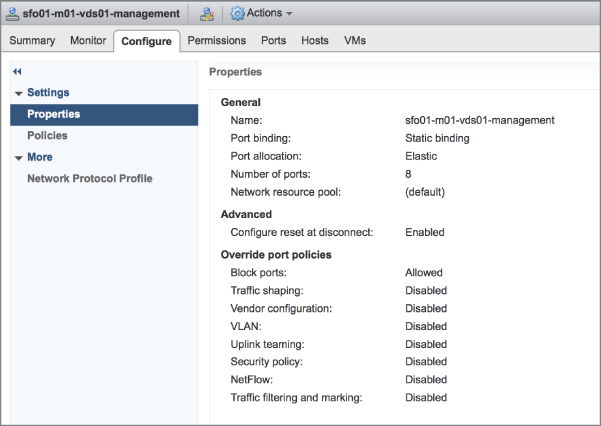
FIGURE 5.53 The vSphere Web Client provides a summary of the distributed port group's configuration.
EDITING A DISTRIBUTED PORT GROUP
To edit the configuration of a distributed port group, use the Edit Distributed Port Group Settings link in the Topology View for the distributed switch. In the vSphere Web Client, you can locate this area by selecting a distributed switch and then going to the Settings area of the Configure tab. Finally, select Topology to produce the Topology view shown in Figure 5.54.

FIGURE 5.54 The Topology view for a distributed switch provides easy access to view and edit distributed port groups.
For now, let's focus on modifying VLAN settings, traffic shaping, and NIC teaming for the distributed port group. Policy settings for security and monitoring are discussed later in this chapter.
Perform the following steps to modify the VLAN settings for a distributed port group:
- Connect to a vCenter Server instance using the vSphere Web Client.
- Navigate to the distributed port group you want to edit.
- Click the Edit Distributed Port Group Settings icon.
- In the Edit Settings dialog box, select the VLAN option from the list of options on the left.
- Modify the VLAN settings by changing the VLAN ID or by changing the VLAN Type setting to VLAN Trunking or Private VLAN.
- Click OK when you have finished making changes.
Follow these steps to modify the traffic-shaping policy for a distributed port group:
- Connect to a vCenter Server instance using the vSphere Web Client.
- Navigate to the distributed port group you want to edit.
- Click the Edit Distributed Port Group Settings icon.
- Select the Traffic Shaping option from the list of options on the left of the distributed port group settings dialog box, as illustrated in Figure 5.55.
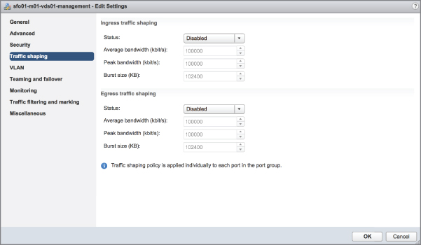
FIGURE 5.55 You can apply both ingress (inbound) and egress (outbound) traffic-shaping policies to a distributed port group on a distributed switch.
Traffic shaping was described in detail earlier, in the section “Using and Configuring Traffic Shaping.” The big difference here is that with a distributed switch, you can apply traffic-shaping policies to both ingress and egress traffic. With vSphere Standard Switches, you could apply traffic-shaping policies only to egress (outbound) traffic. Otherwise, the settings here are for a distributed port group function as described earlier.
- Click OK when you have finished making changes.
Perform the following steps to modify the NIC teaming and failover policies for a distributed port group:
- Connect to a vCenter Server instance using the vSphere Web Client.
- Navigate to the distributed port group you want to edit.
- Click the Edit Distributed Port Group Settings icon.
- Select the Teaming And Failover option from the list of options on the left of the Edit Settings dialog box, as illustrated in Figure 5.56.

FIGURE 5.56 The Teaming And Failover item in the Edit Settings dialog box for the distributed port group provides options for modifying how a distributed port group uses uplinks.
These settings were described in detail in the section “Configuring NIC Teaming,” with one notable exception—version 4.1 and higher distributed switches support Route Based On Physical NIC Load. When this load-balancing policy is selected, ESXi checks the utilization of the uplinks every 30 seconds for congestion. In this case, congestion is defined as either transmit or receive traffic greater than a mean utilization of 75% over a 30-second period. If congestion is detected on an uplink, ESXi will dynamically reassign the virtual machine or VMkernel traffic to a different uplink.
- Click OK when you have finished making changes.
Later in this chapter, the section “Configuring LACP” provides more detail on vSphere's support for Link Aggregation Control Protocol (LACP), including how you would configure a distributed switch for use with LACP. That section also refers back to some of this information on modifying NIC teaming and failover.
If you browse through the available settings, you might notice a Blocked Policy option. This is the equivalent of disabling a group of ports in the distributed port group. Figure 5.57 shows that the Block All Ports setting is set to either Yes or No. If you set the Block Policy to Yes, all traffic to and from that distributed port group is dropped.

FIGURE 5.57 The Block policy is set to either Yes or No. Setting the Block policy to Yes disables all the ports in that distributed port group.
REMOVING A DISTRIBUTED PORT GROUP
To delete a distributed port group, first select the distributed port group. Then, click Delete from the Actions menu. Click Yes to confirm that you do want to delete the distributed port group.
If any virtual machines are still attached to that distributed port group, the vSphere Web Client prevents its deletion and logs an error notification.
To delete the distributed port group to which a virtual machine is attached, you must first reconfigure the virtual machine to use a different distributed port group on the same distributed switch, a distributed port group on a different distributed switch, or a vSphere standard switch. You can use the Migrate Virtual Machines To Another Network command on the Actions menu, or you can just reconfigure the virtual machines network settings directly.
Once all virtual machines have been moved off a distributed port group, you can delete the distributed port group using the process described in the previous paragraphs.
The next section will focus on managing adapters, both physical and virtual, when working with a vSphere Distributed Switch.
Managing VMkernel Adapters
With a distributed switch, managing VMkernel and physical adapters is handled quite differently than with a vSphere standard switch. VMkernel adapters are VMkernel interfaces, so by managing VMkernel adapters, we're really talking about managing VMkernel traffic. Management, vMotion, IP-based storage, vSAN, vSphere Replication, vSphere Replication NFC, and Fault Tolerance logging are all types of VMkernel traffic. Physical adapters are, of course, the physical network adapters that serve as uplinks for the distributed switch. Managing physical adapters involves adding or removing physical adapters connected to ports in the uplinks distributed port group on the distributed switch.
Perform the following steps to add a VMkernel adapter to a distributed switch:
- Connect to a vCenter Server instance using the vSphere Web Client.
- Select Networking in the navigator.
- Select the distributed switch you want to add the VMkernel adapter to.
- Select Add And Manage Hosts from the Actions menu.
- Select the Manage Host Networking radio button, and then click Next.
- On the Select Hosts screen, use the green plus icon to add hosts to the list of hosts that will be modified during this process. Though it seems the wizard is asking you to add hosts to the distributed switch, you're really adding hosts to the list of hosts that will be modified. Click Next when you're ready to move to the next step.
- In this case, we're modifying VMkernel adapters, so make sure only the Manage VMkernel adapters check box is selected. Click Next.
- With an ESXi host selected, click the New Adapter link near the top of the Manage VMkernel Network Adapters screen, shown in Figure 5.58. This opens the Add Networking wizard.

FIGURE 5.58 The Manage VMkernel Network Adapters screen of the wizard allows you to add new adapters as well as migrate existing adapters.
- In the Add Networking wizard, click the Browse button to select the existing distributed port group to which this new virtual adapter should be added. (Refer to the sidebar “Create the Distributed Port Group First” for an important note.) Click OK once you've selected an existing distributed port group, and then click Next.
- On the Port Properties screen, select whether you want to enable IPv4 only, IPv6 only, or both protocols.
- Enable the desired services—like vMotion, v SAN, vSphere Replication, or Fault Tolerance Logging—that should be enabled on this new virtual adapter. Click Next.
- Depending on whether you selected IPv4, IPv6, or IPv4 and IPv6, the next few screens ask you to configure the appropriate network settings.
- If you selected only IPv4, then supply the desired IPv4 settings.
- If you selected only IPv6, then supply the correct IPv6 settings for your network.
- If you selected both IPv4 and IPv6, then there will be two configuration screens in the wizard, one for IPv4 and a separate screen for IPv6.
- Once you've entered the correct network protocol settings, the final screen of the wizard presents the settings that will be applied. If everything is correct, click Finish; otherwise, click the Back button to go back and change settings as necessary.
- This returns you to the Add And Manage Hosts wizard, where you'll now see the new virtual adapter that will be added. Repeat steps 8 through 13 if you need to add a virtual adapter for another ESXi host at the same time; otherwise, click Next.
- The Analyze Impact screen will show you the potential impact of the changes you're making. If necessary, click the Back button to go back and make changes to mitigate any negative impacts. When you're ready to proceed, click Next.
- Click Finish to commit the changes to the selected distributed switch and ESXi hosts.
Migrating an existing virtual adapter, such as a VMkernel port on an existing vSphere standard switch, is done in exactly the same way. The only real difference is that in step 8, you'll select an existing virtual adapter, and then click the Assign Port Group link across the top. Select an existing port group and click OK to return to the wizard, where the screen will look similar to what's shown in Figure 5.59.
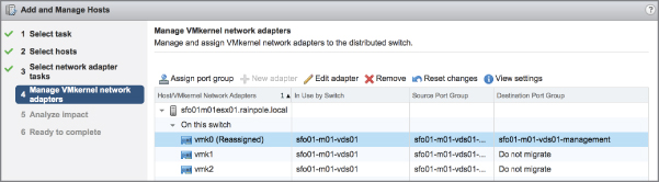
FIGURE 5.59 Migrating a virtual adapter involves assigning it to an existing distributed port group.
After you create or migrate a virtual adapter, you use the same wizard to make changes to the virtual port, such as modifying the IP address, changing the distributed port group to which the adapter is assigned, or enabling features such as vMotion or Fault Tolerance logging. To edit an existing virtual adapter, you'd select the Edit Adapter link seen in Figure 5.59. You would remove VMkernel adapters using this wizard as well, using the Remove link on the Manage Virtual Network Adapters screen of the Add And Manage Hosts wizard.
Not surprisingly, the vSphere Web Client also allows you to add or remove physical adapters connected to ports in the uplinks port group on the distributed switch. Although you can specify physical adapters during the process of adding a host to a distributed switch, as shown earlier, it might be necessary at times to connect a physical NIC to the distributed switch after the host is already participating in it.
Perform the following steps to add a physical network adapter in an ESXi host to a distributed switch:
- Connect to a vCenter Server instance using the vSphere Web Client.
- From the vSphere Web Client home screen, navigate to the distributed switch you'd like to modify.
- From the Actions menu, select Add And Manage Hosts.
- Select the Manage Host Networking radio button, and then click Next.
- Use the green plus icon to add ESXi hosts to the list of hosts that will be affected by the changes in the wizard. Click Next when you're finished adding ESXi hosts to the list.
- Make sure only the Manage Physical Adapters option is selected, as shown in Figure 5.60, and click Next.

FIGURE 5.60 To manage uplinks on a distributed switch, make sure only the Manage Physical Adapters option is selected.
- At the Manage Physical Network Adapters screen, you can add or remove physical network adapters to the selected distributed switch.
- To add a physical adapter as an uplink, select an unassigned adapter from the list and click the Assign Uplink link. You can also use the Assign Uplink link to change the uplink to which a given physical adapter is assigned (for example, to move it from uplink 2 to uplink 3).
- To remove a physical adapter as an uplink, select an assigned adapter from the list and click the Unassign Adapter link.
- To migrate a physical adapter from another switch to this distributed switch, select the already assigned adapter and use the Assign Uplink link. This will automatically remove it from the other switch and assign it to the selected switch.
Repeat this process for each host in the list. Click Next when you're ready to proceed.
- At the Analyze Impact screen, the vSphere Web Client will provide feedback on the anticipated impact of the changes. If the impact of the changes is undesirable, use the Back button to go back and make any necessary changes. Otherwise, click Next.
- Click Finish to complete the wizard and commit the changes.
In addition to migrating VMkernel adapters and modifying the physical adapters, you can use vCenter Server to assist in migrating virtual machine adapters, that is, migrating a virtual machines networking between vSphere standard switches and vSphere distributed switches, as shown in Figure 5.61.
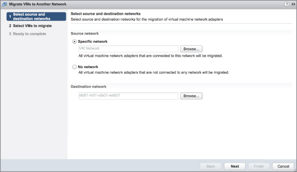
FIGURE 5.61 The Migrate Virtual Machine Networking wizard automates the process of migrating virtual machines between a source and a destination network.
This tool, accessed using the Actions menu when a distributed switch is selected, will reconfigure all selected virtual machines to use the selected destination network. This is much easier than individually reconfiguring virtual machines! In addition, this tool allows you to easily migrate virtual machines both to a distributed switch and from a distributed switch. Let's walk through the process so that you can see how it works.
Perform the following steps to migrate virtual machines from a vSphere Standard Switch to a vSphere Distributed Switch:
- Connect to a vCenter Server instance using the vSphere Web Client.
- Select Networking in the navigator.
- Select a distributed switch from the inventory tree on the left, and then select Migrate VMs To Another Network from the Actions menu. This launches the Migrate Virtual Machine Networking wizard.
- Use the Browse button to select the source network that contains the virtual machines you'd like to migrate. You can use the Filter and Find search boxes to limit the results if you need to. Click OK once you've selected the source network.
- Click the Browse button to select the destination network to which you'd like the virtual machines to be migrated. Again, use the Filter and Find search boxes, where needed, to make it easier to locate the desired destination network. Click OK to return to the wizard once you've selected the destination network.
- Click Next after you've finished selecting the source and destination networks.
- A list of matching virtual machines is generated, and each virtual machine is analyzed to determine if the destination network is accessible or inaccessible to the virtual machine.
Figure 5.62 shows a list with both accessible and inaccessible destination networks. A destination network might show up as inaccessible if the ESXi host on which that virtual machine is running isn't part of the distributed switch. Select the virtual machines you want to migrate; then click Next.
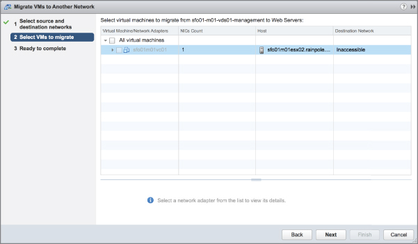
FIGURE 5.62 You cannot migrate virtual machines matching your source network selection if the destination network is listed as inaccessible.
- Click Finish to start the migration of the selected virtual machines from the specified source network to the selected destination network.
You'll see a Reconfigure Virtual Machine task spawn in the Tasks pane for each virtual machine that needs to be migrated.
Keep in mind that this tool can migrate virtual machines from a vSphere standard switch to a distributed switch or from a distributed switch to a standard switch—you only need to specify the source and destination networks accordingly.
Now that we've covered the basics of distributed switches, let's delve into a few advanced topics. First up is network monitoring using NetFlow.
Using NetFlow on vSphere Distributed Switches
NetFlow is a mechanism for efficiently reporting IP-based traffic information as a series of traffic flows. Traffic flows are defined as the combination of source and destination IP addresses, source and destination TCP or UDP ports, IP, and IP Type of Service (ToS). Network devices that support NetFlow will track and report information on the traffic flows, typically sending this information to a NetFlow collector. Using the data collected, network administrators gain detailed insight into the types and amount of traffic flows across the network.
In vSphere 5.0, VMware introduced support for NetFlow with vSphere Distributed Switches (only on distributed switches that are version 5.0.0 or higher). This allows ESXi hosts to gather detailed per-flow information and report that information to a NetFlow collector.
Configuring NetFlow is a two-step process:
- Configure the NetFlow properties on the distributed switch.
- Enable or disable NetFlow (the default is disabled) on a per–distributed port group basis.
To configure the NetFlow properties for a distributed switch, perform these steps:
- Connect to a vCenter Server instance using the vSphere Web Client.
- Navigate to the list of distributed switches and select the distributed switch where you want to enable NetFlow.
- With the desired distributed switch selected, from the Actions menu, select Settings ⇒ Edit NetFlow.
This opens the Edit NetFlow Settings dialog box.
- As shown in Figure 5.63, specify the IP address of the NetFlow collector, the port on the NetFlow collector, and an IP address to identify the distributed switch.
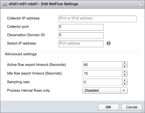
FIGURE 5.63 You'll need the IP address and port number for the NetFlow collector in order to send flow information from a distributed switch.
- You can modify the Advanced Settings if advised to do so by your NetFlow collector.
- If you want the distributed switch to process only internal traffic flows, that is, traffic flows from virtual machine to virtual machine on the same ESXi host—set Process Internal Flows Only To Enabled.
- Click OK to commit the changes and return to the vSphere Web Client.
After you configure the NetFlow properties for the distributed switch, you then enable NetFlow on a per–distributed port group basis. The default setting is Disabled.
Perform these steps to enable NetFlow on a specific distributed port group:
- In the vSphere Web Client, navigate to the distributed switch hosting the distributed port group where you want to enable NetFlow. You must have already performed the previous procedure to configure NetFlow on that distributed switch.
- From the Actions menu, select Distributed Port Groups ⇒ Manage Distributed Port Groups. This opens the Manage Distributed Port Groups wizard. This can also be accomplished by right-clicking the distributed port group and selecting Edit Settings.
- Place a check mark next to Monitoring, and then click Next.
- In the Select port groups window, click the Select Distributed Port Groups icon, select the distributed ports groups to edit, and click OK.
Click Next once you've selected the desired distributed port groups.
- At the Monitoring screen, shown in Figure 5.64, set NetFlow to Enabled; then click Next.
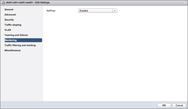
FIGURE 5.64 NetFlow is disabled by default. You enable NetFlow on a per–distributed port group basis.
- Click Finish to save the changes to the distributed port group.
This distributed port group will start capturing NetFlow statistics and reporting that information to the specified NetFlow collector.
Another feature that is quite useful is vSphere's support for switch discovery protocols, like Cisco Discovery Protocol (CDP) and Link Layer Discovery Protocol (LLDP). The next section shows you how to enable these protocols in vSphere.
Enabling Switch Discovery Protocols
Previous versions of vSphere supported Cisco Discovery Protocol (CDP), a protocol for exchanging information between network devices. However, it required using the command line to enable and configure CDP.
In vSphere 5.0, VMware added support for Link Layer Discovery Protocol (LLDP), an industry standard discovery protocol, and provided a location within the vSphere Client where CDP/LLDP support can be configured.
Perform the following steps to configure switch discovery support:
- Connect to a vCenter Server instance using the vSphere Web Client.
- With the distributed switch selected, select the Configure tab.
- Under Settings, select Properties.
- Click the Edit button and then select Advanced in the Edit Settings dialog box to configure the distributed switch for CDP or LLDP support, as shown in Figure 5.65.

FIGURE 5.65 LLDP support enables distributed switches to exchange discovery information with other LLDP-enabled devices over the network.
This figure shows the distributed switch configured for LLDP support, both listening (receiving LLDP information from other connected devices) and advertising (sending LLDP information to other connected devices).
- Click OK to save your changes.
Once the ESXi hosts participating in this distributed switch start exchanging discovery information, you can view that information from the physical switch(es). For example, on most Cisco switches, the show cdp neighbor command will display information about CDP-enabled network devices, including ESXi hosts. Entries for ESXi hosts will include information on the physical NIC used and the vSwitch involved.
vSphere Standard Switches also support CDP, though not LLDP, but there is no GUI for configuring this support; you must use esxcli. This command will set CDP to Both (listen and advertise) on vSwitch0:
esxcli network vswitch standard set --cdp-status=both --vswitch-name=vSwitch0 Enabling Enhanced Multicast Functions
On top of basic multicast filtering supported by the vSphere Standard Switch, the vSphere Distributed Switch also supports multicast snooping.
In this mode, the distributed switch learns about the membership of a virtual machine dynamically. This is achieved by monitoring virtual machine traffic and capturing IGMP or multicast listener discovery (MLD) details when a virtual machine sends a packet containing this information. The distributed switch then creates a record of the destination IP address of the group, and for IGMPv3 it also records the source IP address from which the virtual machine prefers to receive traffic. The distributed switch will remove the entry containing the group details if a virtual machine does not renew its membership within a certain period of time.
Perform the following steps to enable multicast snooping on a vSphere Distributed Switch:
- Connect to a vCenter Server instance using the vSphere Web Client.
- Select Networking in the navigator.
- Select an existing distributed switch, right-click the distributed switch, and select Settings ⇒ Edit Settings.
- In the dialog box, select Advanced and then change the multicast filtering mode to IGMP/MLD snooping, as shown in Figure 5.66.
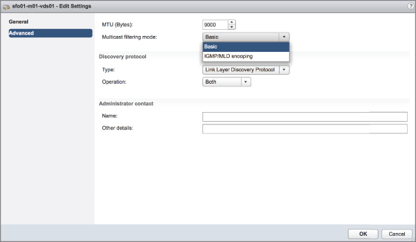
FIGURE 5.66 The vSphere Distributed Switch supports both basic multicast filtering and IGMP/MLD snooping.
Setting Up Private VLANs
Private VLANs (PVLANs) are an advanced networking feature of vSphere that build on the functionality of vSphere Distributed Switches. Within the vSphere environment, PVLANs are possible only when using distributed switches and are not available to use with vSphere Standard Switches. Further, you must ensure that the upstream physical switches to which your vSphere environment is connected also support PVLANs.
Here is a quick overview of private VLANs. PVLANs are a way to further isolate ports within a given VLAN. For example, consider the scenario of hosts within a demilitarized zone (DMZ). Hosts within a DMZ rarely need to communicate with each other, but using a VLAN for each host quickly becomes unwieldy for a number of reasons. By using PVLANs, you can isolate hosts from each other while keeping them on the same IP subnet. Figure 5.67 provides a graphical overview of how PVLANs work.

FIGURE 5.67 Private VLAN entries consist of a primary VLAN and one or more secondary VLAN entries.
PVLANs are configured in pairs: the primary VLAN and any secondary VLANs. The primary VLAN is considered the downstream VLAN; that is, traffic to the host travels along the primary VLAN. The secondary VLAN is considered the upstream VLAN; that is, traffic from the host travels along the secondary VLAN.
To use PVLANs, first configure the PVLANs on the physical switches connecting to the ESXi hosts, and then add the PVLAN entries to the distributed switch in vCenter Server.
Perform the following steps to define PVLAN entries on a distributed switch:
- Connect to a vCenter Server instance using the vSphere Web Client.
- Select Networking in the navigator.
- Select an existing distributed switch and click the Configure tab.
- Select Private VLAN; then click the Edit button.
- In the Edit Private VLAN Settings dialog box, click Add to add a primary VLAN ID to the list on the left.
- For each primary VLAN ID in the list on the left, add one or more secondary VLANs to the list on the right, as shown previously in Figure 5.67.
Secondary VLANs are classified as one of the two following types:
- Isolated: Ports placed in secondary PVLANs configured as isolated are allowed to communicate only with promiscuous ports in the same secondary VLAN. (We'll explain promiscuous ports later in this chapter.)
- Community: Ports in a secondary PVLAN are allowed to communicate with other ports in the same secondary PVLAN as well as with promiscuous ports.
Only one isolated secondary VLAN is permitted for each primary VLAN. Multiple secondary VLANs configured as community VLANs are allowed.
- When you finish adding all the PVLAN pairs, click OK to save the changes and return to the vSphere Web Client.
After you enter the PVLAN IDs for a distributed switch, you must create a distributed port group that takes advantage of the PVLAN configuration. The process for creating a distributed port group was described earlier. Figure 5.68 shows the New Distributed Port Group wizard for a distributed port group that uses PVLANs.
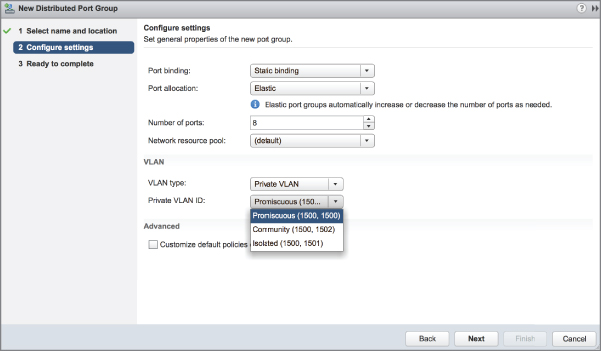
FIGURE 5.68 When a distributed port group is created with PVLANs, the distributed port group is associated with both the primary VLAN ID and a secondary VLAN ID.
In Figure 5.68, you can see the term promiscuous again. In PVLAN parlance, a promiscuous port is allowed to send and receive Layer 2 frames to any other port in the VLAN. This type of port is typically reserved for the default gateway for an IP subnet—for example, a Layer 3 router.
PVLANs are a powerful configuration tool but also a complex configuration topic and one that can be difficult to understand, let alone troubleshoot when communications issues occur. For additional information on PVLANs, we recommend that you visit https://kb.vmware.com/s/article/1010691.
As with vSphere Standard Switches, vSphere Distributed Switches provide a tremendous amount of flexibility in designing and configuring a virtual network. But, as with all things, there are limits to the flexibility. Table 5.2 lists some of the configuration maximums for vSphere Distributed Switches.
TABLE 5.2: Configuration maximums for ESXi networking components (vSphere Distributed Switches)
| CONFIGURATION ITEM | MAXIMUM |
| Switches per vCenter Server | 128 |
| Maximum ports per host (vSS/vDS) | 4,096 |
| vDS ports per vCenter instance | 60,000 |
| ESXi hosts per vDS | 2,000 |
| Static port groups per vCenter instance | 10,000 |
| Ephemeral port groups per vCenter instance | 1,016 |
Configuring LACP
Link Aggregation Control Protocol (LACP) is a standardized protocol for supporting the aggregation, or joining, of multiple individual network links into a single, logical network link. Note that LACP support is available only when you are using a vSphere Distributed Switch; vSphere Standard Switches do not support LACP.
We'll start with a review of how to configure basic LACP support on a version 5.1.0 vSphere Distributed Switch; then we'll show you how the LACP support has been enhanced in vSphere 5.5 and above.
Using a version 5.1.0 vSphere Distributed Switch, you must configure the following four areas:
- Enable LACP in the properties for the distributed switch's uplink group.
- Set the NIC teaming policy for all distributed port groups to Route Based On IP Hash.
- Set the network detection policy for all distributed port groups to link status only.
- Configure all distributed port groups so that all uplinks are active, not standby or unused.
Figure 5.69 shows the Edit Settings dialog box for the uplink group on a version 5.1.0 vSphere Distributed Switch. You can see here the setting for enabling LACP as well as the reminder of the other settings that are required.

FIGURE 5.69 Basic LACP support in a version 5.1.0 vSphere Distributed Switch is enabled in the uplink group but requires other settings as well.
You must configure LACP on the physical switch to which the ESXi host is connected; the exact way you enable LACP will vary from vendor to vendor. The Mode setting shown in Figure 5.69—which is set to either Active or Passive—helps dictate how the ESXi host will communicate with the physical switch to establish the link aggregate:
- When LACP Mode is set to Passive, the ESXi host won't initiate any communications to the physical switch; the switch must initiate the negotiation.
- When LACP Mode is set to Active, the ESXi host will actively initiate the negotiation of the link aggregation with the physical switch.
You can probably gather from this discussion of using LACP with a version 5.1.0 vSphere Distributed Switch that only a single link aggregate (a single bundle of LACP-negotiated links) is supported and LACP is enabled or disabled for the entire vSphere Distributed Switch.
When you upgrade to a version 5.5.0 or 6.0.0 vSphere Distributed Switch, though, the LACP support is enhanced to eliminate these limitations. Version 5.5.0 and later distributed switches support multiple LACP groups, and how those LACP groups are used (or not used) can be configured on a per–distributed port group basis. Let's take a look at how you'd configure LACP support with a version 6.6 distributed switch.
As was introduced with the version 5.5.0 distributed switch, a new LACP section appears in the Settings area of the Configure tab, as shown in Figure 5.70. From this area, you'll define one or more link aggregation groups (LAGs), each of which will appear as a logical uplink to the distributed port groups on that distributed switch. vSphere 5.5 and later support multiple LAGs on a single distributed switch, which allows administrators to dual-home distributed switches (connect distributed switches to multiple upstream physical switches) while still using LACP. There are a few limitations, which are described near the end of this section.

FIGURE 5.70 Enhanced LACP support in vSphere 5.5 and later eliminates many of the limitations of the support found in vSphere 5.1.
To use LACP with a version 5.5.0 or later distributed switch, you must follow three steps:
- Define one or more LAGs in the LACP section of the Settings area of the Manage tab.
- Add physical adapters into the LAG(s) you've created.
- Modify the distributed port groups to use those LAGs as uplinks in the distributed port groups' teaming and failover configuration.
Let's take a look at each of these steps in a bit more detail.
To create a LAG, perform these steps:
- Connect to a vCenter Server instance using the vSphere Web Client.
- Navigate to the specific distributed switch for which you want to configure a LACP link aggregation group.
- With the distributed switch selected, click the Configure tab, and then click LACP. This displays the screen shown earlier in Figure 5.70.
- Click the green plus symbol to add a LAG. This displays the New Link Aggregation Group dialog box, shown in Figure 5.71.
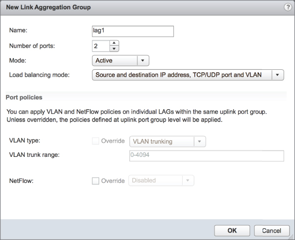
FIGURE 5.71 With a version 5.5.0 or newer distributed switch, the LACP properties are configured on a per-LAG basis instead of for the entire distributed switch.
- In the New Link Aggregation Group dialog box, specify a name for the new LAG.
- Specify the number of physical ports that will be included in the LAG.
- Specify the LACP mode—either Active or Passive, as we described earlier—that this LAG should use.
- Select a load-balancing mode. Note that this load-balancing mode affects only outbound traffic; inbound traffic will be load balanced according to the load-balancing mode configured on the physical switch. (For best results and ease of troubleshooting, the configuration here should match the configuration on the physical switch where possible.)
- If you need to override port policies for this LAG, you can do so at the bottom of this dialog box.
- Click OK to create the new LAG and return to the LACP area of the vSphere Web Client.
Now that at least one LAG has been created, you need to assign physical adapters to it. To do this, you'll follow the process outlined earlier for managing physical adapters (see the section “Managing VMkernel Adapters” for the specific details). The one change you'll note is that when you click the Assign Uplink link for a selected physical adapter, you'll now see an option to assign that adapter to one of the available uplink ports in the LAG(s) that you created. Figure 5.72 shows the dialog box for assigning an uplink for a distributed switch with two LAGs.

FIGURE 5.72 Once a LAG has been created, physical adapters can be added to it.
Once you've added physical adapters to the LAG(s), you can proceed with the final step: configuring the LAG(s) as uplinks for the distributed port groups on that distributed switch. Specific instructions for this process were given earlier, in the section “Editing a Distributed Port Group.” Note that the LAG(s) will appear as physical uplinks in the teaming and failover configuration, as you can see in Figure 5.73. You can assign the LAG as an active uplink, a standby uplink, or an unused uplink.

FIGURE 5.73 LAGs appear as physical uplinks to the distributed port groups.
When using LAGs, you should be aware of the following limitations:
- Some vSphere features such as Host Profiles, Port Mirroring, teaming Health Check, and the Netdump collector cannot be used with a LAG. See VMware KB 2051307.
- When you use a LAG, you lose benefits of the distributed switch such as the Route based on physical NIC load teaming algorithm.
- You can't mix LAGs and physical uplinks for a given distributed port group. Any physical uplinks must be listed as unused adapters.
- You can't use multiple active LAGs on a single distributed port group. Place one LAG in the active uplinks list; place any other LAGs in the list of unused uplinks.
- VMware only supports a LAG connected to the same physical switch, or switch stack. When coupled with the previous bullet point, you can see that traffic can only use one physical switch until a switch or LAG failure. See VMware KB 1001938.
Note that some of these limitations are per distributed port group; you can use different active LAGs or stand-alone uplinks with other distributed port groups because the teaming and failover configuration is set for each individual distributed port group.
Configuring Virtual Switch Security
Even though vSwitches and distributed switches are considered to be “dumb switches,” you can configure them with security policies to enhance or ensure Layer 2 security. For vSphere Standard Switches, you can apply security policies at the vSwitch or at the port group level. For vSphere Distributed Switches, you apply security policies only at the distributed port group level. The security settings include the following three options:
- Promiscuous mode
- MAC address changes
- Forged transmits
Applying a security policy to a vSwitch is effective, by default, for all connection types within the switch. However, if a port group on that vSwitch is configured with a competing security policy, it will override the policy set at the vSwitch. For example, if a vSwitch is configured with a security policy that rejects MAC address changes, but a port group on the switch is configured to accept MAC address changes, then any virtual machines connected to that port group will be allowed to communicate even though it is using a MAC address that differs from what is configured in its VMX file.
The default security profile for a vSwitch, shown in Figure 5.74, is set to reject Promiscuous mode and to accept MAC address changes and forged transmits. Similarly, Figure 5.75 shows the default security profile for a distributed port group on a distributed switch.

FIGURE 5.74 The default security profile for a standard switch prevents Promiscuous mode but allows MAC address changes and forged transmits.
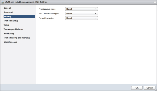
FIGURE 5.75 The default security profile for a distributed port group on a distributed switch also denies MAC address changes and forged transmits.
Each of these security options is explored in more detail in the following sections.
Understanding and Using Promiscuous Mode
The Promiscuous Mode option is set to Reject by default to prevent virtual network adapters from observing any of the traffic submitted through a vSwitch or distributed switch. For enhanced security, allowing Promiscuous mode is not recommended, because it is an insecure mode of operation that allows a virtual adapter to access traffic other than its own. Despite the security concerns, there are valid reasons for permitting a switch to operate in Promiscuous mode. An intrusion-detection system (IDS) must be able to identify all traffic to scan for anomalies and malicious patterns of traffic, for example.
Previously in this chapter, we talked about how port groups and VLANs did not have a one-to-one relationship and that occasions may arise when you have multiple port groups on a standard/distributed switch configured with the same VLAN ID. This is exactly one of those situations—you need a system, the IDS, to see traffic intended for other virtual network adapters. Rather than granting that ability to all the systems on a port group, you can create a dedicated port group for just the IDS system. It will have the same VLAN ID and other settings but will allow Promiscuous mode instead of rejecting it. This enables you, the administrator, to carefully control which systems are allowed to use this powerful and potentially security-threatening feature.
As shown in Figure 5.76, the virtual switch security policy will remain at the default setting of Reject for the Promiscuous Mode option, while the Virtual Machine Port Group for the IDS will be set to Accept. This setting will override the virtual switch, allowing the IDS to monitor all traffic for that VLAN.
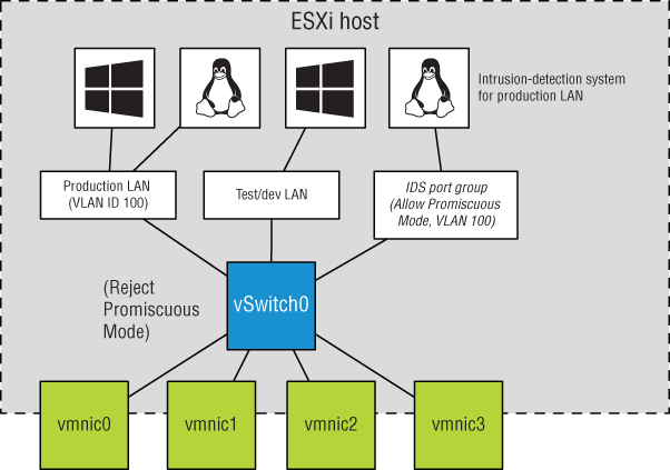
FIGURE 5.76 Promiscuous mode, though it reduces security, is required when using an intrusion-detection system.
Allowing MAC Address Changes and Forged Transmits
When a virtual machine is created with one or more virtual network adapters, a MAC address is generated for each virtual adapter. Just as Intel, Broadcom, and others manufacture network adapters that include unique MAC address strings, VMware is a network adapter manufacturer that has its own MAC prefix to ensure uniqueness. Of course, VMware doesn't actually manufacture anything, because the product exists as a virtual NIC in a virtual machine. You can see the 6-byte, randomly generated MAC addresses for a virtual machine in the configuration file (VMX) of the virtual machine as well as in the Settings area for a virtual machine within the vSphere Web Client, shown in Figure 5.77. A VMware-assigned MAC address begins with the prefix 00:50:56 or 00:0C:29. The fifth and sixth sets (YY:ZZ) are generated randomly based on the universally unique identifier (UUID) of the virtual machine that is tied to the location of the virtual machine. For this reason, when a virtual machine location is changed, a prompt appears prior to successful boot. The prompt inquires about keeping the UUID or generating a new UUID, which helps prevent MAC address conflicts.

FIGURE 5.77 A virtual machine's initial MAC address is automatically generated and listed in the configuration file for the virtual machine and displayed within the vSphere Web Client.
All virtual machines have two MAC addresses: the initial MAC and the effective MAC. The initial MAC address is the MAC address discussed in the previous paragraph that is generated automatically and resides in the configuration file. The guest OS has no control over the initial MAC address. The effective MAC address is the MAC address configured by the guest OS that is used during communication with other systems. The effective MAC address is included in network communication as the source MAC of the virtual machine. By default, these two addresses are identical. To force a non-VMware-assigned MAC address to a guest operating system, change the effective MAC address from within the guest OS, as shown in Figure 5.78.
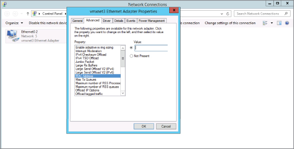
FIGURE 5.78 A virtual machine's source MAC address is the effective MAC address, which by default matches the initial MAC address configured in the VMX file. The guest OS, however, may change the effective MAC address.
The ability to alter the effective MAC address cannot be removed from the guest OS. However, you can deny or allow the system to function with this altered MAC address through the security policy of a standard switch or distributed port group. The remaining two settings of a virtual switch security policy are MAC Address Changes and Forged Transmits. These security policies allow or deny differences between the initial MAC address in the configuration file and the effective MAC address in the guest OS. As noted earlier, the default security policy is to accept the differences and process traffic as needed.
The difference between the MAC Address Changes and Forged Transmits security settings involves the direction of the traffic. MAC Address Changes is concerned with the integrity of incoming traffic. If the option is set to Reject, traffic will not be passed through the standard switch or distributed port group to the virtual machine (incoming) if the initial and the effective MAC addresses do not match. Forged Transmits oversees the integrity of outgoing traffic, and if this option is set to Reject, traffic will not be passed from the virtual machine to the standard switch or distributed port group (outgoing) if the initial and the effective MAC addresses do not match. Figure 5.79 highlights the security restrictions implemented when MAC Address Changes and Forged Transmits are set to Reject.
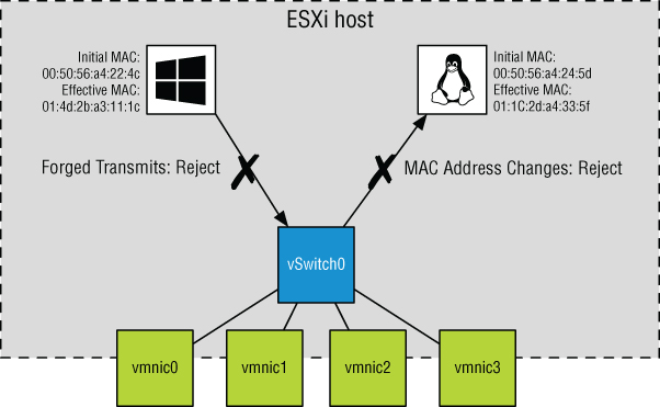
FIGURE 5.79 The MAC Address Changes and Forged Transmits security options deal with incoming and outgoing traffic, respectively.
For the highest level of security, VMware recommends setting MAC Address Changes, Forged Transmits, and Promiscuous Mode on each standard switch or distributed port group to Reject. When warranted or necessary, use port groups to loosen the security for a subset of virtual machines to connect to the port group.
Perform the following steps to edit the security profile of a vSwitch:
- Connect to a vCenter Server instance using the vSphere Web Client.
- Navigate to the specific ESXi host that has the vSphere Standard Switch you'd like to edit.
- With an ESXi host selected in the inventory list on the left, click the Configure tab, and then click Virtual Switches.
- From the list of virtual switches, select the vSphere Standard Switch you'd like to edit, and click the Edit link (it looks like a pencil). This opens the Edit Settings dialog box for the selected vSwitch.
- Click Security on the list on the left side of the dialog box and make the necessary adjustments.
- Click OK.
Perform the following steps to edit the security profile of a port group on a vSwitch:
- Connect to a vCenter Server instance using the vSphere Web Client.
- Navigate to the specific ESXi host and vSphere Standard Switch that contains the port group you wish to edit.
- Click the name of the port group under the graphical representation of the virtual switch, and then click the Edit link.
- Click Security and make the necessary adjustments. You'll need to place a check mark in the Override box to allow the port group to use a different setting than its parent virtual switch.
- Click OK to save your changes.
Perform the following steps to edit the security profile of a distributed port group on a vSphere Distributed Switch:
- Connect to a vCenter Server instance using the vSphere Web Client.
- Select Networking in the navigator.
- Select an existing distributed port group, and then click the Edit Distributed Port Group sSettings icon.
- Select Security from the list of policy options on the left side of the dialog box.
- Make the necessary adjustments to the security policy.
- Click OK to save the changes.
If you need to make the same security-related change to multiple distributed port groups, you can use the Manage Distributed Port Groups command on the Actions menu to perform the same configuration task for multiple distributed port groups at the same time.
Managing the security of a virtual network architecture is much the same as managing the security for any other portion of your information systems. Security policy should dictate that settings be configured as secure as possible to err on the side of caution. Only with proper authorization, documentation, and change management processes should security be reduced. In addition, the reduction in security should be as controlled as possible to affect the least number of systems if not just the systems requiring the adjustments.
In the next chapter, we'll dive deep into storage in VMware vSphere, a critical component of your vSphere environment.
The Bottom Line
- Identify the components of virtual networking. Virtual networking is a blend of virtual switches, physical switches, VLANs, physical network adapters, VMkernel adapters, uplinks, NIC teaming, virtual machines, and port groups.
- Master It What factors contribute to the design of a virtual network and the components involved?
- Create virtual switches and distributed virtual switches. vSphere supports both vSphere Standard Switches and vSphere Distributed Switches. vSphere Distributed Switches bring new functionality to the vSphere networking environment, including private VLANs and a centralized point of management for ESXi clusters.
- Master It You've asked a fellow vSphere administrator to create a vSphere Distributed Switch for you, but the administrator can't complete the task because he can't find out how to do this with an ESXi host selected in the vSphere Client. What should you tell this administrator?
- Create and manage NIC teaming, VLANs, and private VLANs. NIC teaming allows virtual switches to have redundant network connections to the rest of the network. Virtual switches also provide support for VLANs, which provide logical segmentation of the network, and private VLANs, which provide added security to existing VLANs while allowing systems to share the same IP subnet.
- Master It You'd like to use NIC teaming to make the best use of physical uplinks for both greater redundancy and improved throughput, even under network contention. Which load-balancing policy on the distributed switch should you use?
- Master It How do you configure both a vSphere Standard Switch and a vSphere Distributed Switch to pass VLAN tags all the way up to a guest OS?
- Configure virtual switch security policies. Virtual switches support security policies for allowing or rejecting Promiscuous mode, allowing or rejecting MAC address changes, and allowing or rejecting forged transmits. All of the security options can help increase Layer 2 security.
- Master It You have a networking application that needs to see traffic on the virtual network that is intended for other production systems on the same VLAN. The networking application accomplishes this by using Promiscuous mode. How can you accommodate the needs of this networking application without sacrificing the security of the entire virtual switch?
- Master It Another vSphere administrator on your team is trying to configure the security policies on a distributed switch but is having some difficulty. What could be the problem?