Chapter 11
Managing Resource Allocation
The ability for a single physical server to host many virtual machines (VMs) has a massive value in today's modern datacenters. But let's face it: there are limits to how many VMs can run on a VMware ESXi host. To make the most of the platform, you need to understand how the four key resources—memory, processors, disks, and networks—are consumed by the VMs running on the host, and how the host consumes those resources. The methods used to arbitrate access to each of these resources on an ESXi host are a bit different. This chapter discusses how an ESXi host allocates these resources and how you can change the way these resources are consumed.
Reviewing Virtual Machine Resource Allocation
A significant advantage of server virtualization is the ability to allocate resources to a virtual machine (VM) based on the actual performance requirements for the guest OS and application or services. In legacy physical server environments, a server was often provided more resources than the application or services required because it was purchased with a specific budget and the server specifications were maximized for the budget provided.
For example, consider a simple Dynamic Host Configuration Protocol (DHCP) server. Based on an average, entry-level rackmount server, would DHCP services really benefit from a server with dual socket, 10-core processors, 32 GB of memory, and mirrored 240 GB solid state drives? And does it really need to consume a minimum of 1U of rack space in the datacenter along with its own three- or five-year service contract? In most situations, the services will underutilize the server resources.
With server virtualization, you can create a VM that is ideally suited for the DHCP server role. For example, you could create a VM with a more-suitable 2 GB or 4 GB of memory (depending on the guest OS), a single CPU, and 20 GB to 40 GB of disk space, all of which are provided by the ESXi host on which the VM is running. With the remaining resources, you can create additional VMs with the resources they need to effectively operative without the overallocation of valuable memory, CPU, and storage.
Allocating resources based on the required or the anticipated need of the guest OS and the applications or services that will run inside a VM is the essence of right-sizing your workloads, which we discussed in Chapter 9, “Creating and Managing Virtual Machines.” By right-sizing the VMs in your organization, it allows you to achieve greater efficiency and higher consolidation ratios—more VMs per physical server in your datacenter.
However, even when you right-size and add more and more VMs to the platform, each VM places additional demands on the ESXi host as the resources are consumed to support the workloads. At some point, a host will run out of one, or more, of these key resources. For example, consider the following resource management situations.
- What does an ESXi host do when it runs out of resources?
- How does an ESXi host manage VMs that are requesting more resources than the physical server can provide?
- How can you guarantee that a guest OS and its applications and services get the resources they need without being starved by VMs (e.g., a “noisy neighbor”)?
VMware vSphere offers a set of controls designed to guarantee access to resources when necessary, control the use of resources, and prioritize access to resources when available resources are low. Specifically, VMware vSphere offers three methods for controlling or modifying resource allocation: reservations, limits, and shares.
The behavior of these mechanisms varies based on the resource, but the fundamental concepts of each mechanism are as follows:
- Reservations Reservations act as guarantees for a resource type. Reservations may be used when you want to ensure that, no matter what else is going on, a specific VM or set of VMs is assured access to a set amount of a resource from startup through shutdown.
- Limits Limits restrict the amount of a resource type that a VM can consume. By default, a VM has a limit applied based on how it's constructed. For example, a VM that is configured with a single virtual CPU (vCPU) is limited to using only that single vCPU. This vSphere feature offers you an even greater level of granularity over how the resources are used. Depending on the resource type for which the limit is being applied, the specific behavior of ESXi will change. We will discuss this in detail in this chapter under the sections for each resource type.
- Shares Shares establish priority during periods of contention. When VMs compete for limited resources, an ESXi host prioritizes which VMs move to the front of the queue to gain access to the resources. The feature determines the priority. The VMs with higher share value will be marked for higher priority and therefore will receive prioritized access to an ESXi host's resources.
Figure 11.1: shows these three mechanisms displayed in the properties of a VM.

FIGURE 11.1 Reservations, limits, and shares offer fine-grained control over resource allocation.
Throughout the chapter, we will discuss how one or more of these three methods—reservations, limits, and shares—are applied to control or modify resource allocation across all four key resources in a vSphere environment: memory, CPU, storage, and network.
The first VM resource-type that we will examine is memory. Memory is often the first resource to become constrained in an environment, so let's start there.
Working with Virtual Machine Memory
We will begin with a discussion of how memory is allocated to a VM. Later, we will discuss how you can use reservations, shares, and limits to help control or modify how your VMs consume memory.
When you create a new VM in the vSphere Web Client, you are asked how much memory you would like to assign. The vSphere Web Client will suggest a default value based on the recommended configuration for the selected guest OS (the selected guest OS in this case is Microsoft Windows Server 2016 64-bit), as shown in Figure 11.2.

FIGURE 11.2 The memory configuration settings for a VM indicate the amount of memory the VM “thinks” it has.
The amount of memory you allocate is the amount the guest OS will see—in this example, 4,096 MB. This is the same as if you build a physical server and insert a set of four 1,024 MB DIMMs into the system board. When you install the Microsoft Windows Server 2016 guest OS onto this VM, the guest OS will report 4,096 MB of memory. Additionally, the memory that the VM has been allocated during the configuration is the maximum amount of memory the guest OS will be able to access—the default upper limit. Like a physical server with four 1,024 MB DIMMs installed, this VM will not be able to use more than 4,096 MB of memory provided by an ESXi host.
Assume for a moment that you have a single ESXi host with 32 GB of memory available to run VMs for your organization. For the sake of math, let's also assume that hypervisor is using some host memory and there's 32 GB available for the VMs to consume. In the case of the new VM, it will comfortably run, leaving approximately 28 GB of memory for other workloads. (There is some additional overhead that we will discuss later, but for now let's assume that the 28 GB is available to other workloads.)
What happens when you run seven more VMs, each configured with 4 GB? Each additional VM will request 4 GB of memory from the ESXi host. At this point, eight VMs will be accessing the physical memory, and you will have allocated all 32 GB of memory to the workloads. The ESXi hypervisor has now run out of a critical resource: memory.
What happens when you create a ninth VM—will it power on? If this is a cluster and you have configured vSphere High Availability admission control to allow it, then the short answer is yes, and some of the key technologies that enable administrators to overcommit memory—that is, to allocate more memory to VMs than is physically installed on the ESXi host—are quite advanced. Because these technologies are integral to understanding how memory allocation works with VMware vSphere, let's examine these technology features and how they work.
Understanding ESXi Advanced Memory Technologies
VMware ESXi supports many technology features for advanced memory management. ESXi is capable of performing memory over commitment in a manner that is guest OS agnostic.
VMware ESXi uses five different memory-management technologies to ensure the host memory is used as efficiently as possible: idle memory tax, transparent page sharing, ballooning, memory compression, and swapping.
If you are interested in more in-depth information on some of these memory management technologies, we recommend reading “Memory Resource Management in VMware ESX Server,” by Carl A. Waldspurger, available online at
http://www.waldspurger.org/carl/papers/esx-mem-osdi02.pdf.
IDLE MEMORY TAX
Before VMware ESXi actively starts making changes to relieve memory pressure, it ensures that VMs are not actively hording memory by charging more for the idle memory. Up to 75% of the memory allocated to each VM can be borrowed to service another through the Idle Memory Tax (IMT).
This setting is configurable on a per-VM basis within the Advanced Virtual Machine Settings (see Chapter 9). Under most circumstances, it is not necessary, nor recommended, to modify the IMT unless there is a specific requirement.
Inside each guest OS, VMware Tools should be installed and running where it will use the balloon driver to determine which memory blocks are allocated but idle and, therefore, available to be borrowed. The balloon driver is also used in a more active fashion, which we will discuss later in this chapter.
TRANSPARENT PAGE SHARING
The next memory-management technology ESXi uses is transparent page sharing (TPS), in which identical memory pages are shared among VMs to reduce the total number of memory pages consumed. The hypervisor computes hashes of the contents of memory pages to identify pages that contain identical memory. If it finds a match, TPS compares the matching memory pages to exclude any false positives. Once the pages are confirmed to be identical, the hypervisor will transparently remap the memory pages of the VMs to share the same physical memory page and thereby reduce overall host memory consumption. Advanced parameters are also available to fine-tune the behavior of the page-sharing techniques.
Normally, ESXi works on 4 KB memory pages and will use transparent page sharing on all memory pages. However, when the hypervisor is taking advantage of hardware offloads available in the CPUs—such as Intel Extended Page Tables (EPT) Hardware Assist or AMD Rapid Virtualization Indexing (RVI) Hardware Assist—then the hypervisor uses 2 MB memory pages, also known as large pages. In these cases, ESXi will not share these large pages, but it will compute hashes for the 4 KB pages inside the large pages. If the hypervisor needs to invoke swapping, the large pages are broken into small pages. Having these hashes already computed allows the hypervisor to invoke the page sharing before they are swapped out.
BALLOONING
As we previously discussed, ESXi memory-management technologies are guest OS agnostic—the choice of VM guest OS does not matter. While any supported guest OS can take advantage of all the ESXi memory management techniques, these technologies are not necessarily guest OS independent—meaning that they operate without interaction from the guest OS. While transparent page sharing operates independently of the guest OS, ballooning does not.
Ballooning involves the use of a driver—referred to as the balloon driver—installed into the guest OS. The balloon driver is included as part of VMware Tools and is subsequently deployed when the package is installed on a guest OS. The balloon driver responds to commands from the hypervisor to reclaim memory from the VM's guest OS. The balloon driver does this by requesting memory from the guest OS—a process called inflating—and then passing that memory back to the hypervisor for use by other VM workloads.
Because the guest OS can surrender the pages it is no longer using when the balloon driver requests memory, the hypervisor reclaims memory without any performance impact on the applications running inside that guest OS. If the guest OS is already under memory pressure such that the memory configured for the VM is insufficient for the guest OS and its applications, it is likely that inflating the balloon driver will invoke guest OS paging (swapping). This will impair the workload performance.
MEMORY COMPRESSION
Memory compression is an additional memory-management technique that an ESXi host has at its disposal. When an ESXi host reaches the point where hypervisor swapping is necessary, the VMkernel will attempt to compress memory pages and keep them in memory in a compressed memory cache. Pages that can be successfully compressed by at least 50% are placed into the compressed memory cache instead of being written to disk and can then be recovered far faster if the guest OS needs to access the memory page. Memory compression can dramatically reduce the number of pages that must be swapped to disk and improves the performance of an ESXi host that is under strong memory pressure. By default, 10% of VM memory is used for the compression cache; however, this figure is configurable. The percentage initiates at zero and grows to the default or configured value when the VM memory starts to swap. Compression is only invoked when the ESXi host reaches the point that VMkernel swapping is required.
SWAPPING
Two forms of swapping are involved in managing memory in ESXi. The first is guest OS swapping, in which the guest OS inside the VM swaps pages out to its own virtual disk according to its memory management algorithms. Generally, this is due to memory requirements that are higher than available memory. In a virtualized environment, this translates to a VM being configured with less memory than the guest OS and its applications or services require, such as trying to run Windows Server 2016 with only 1 GB of memory and an application server. Guest OS swapping falls strictly under the control of the guest OS and is not controlled by the hypervisor.
The second type of swapping is hypervisor swapping. When none of the previously described technologies—transparent page sharing, ballooning, and memory compression—trim guest OS memory usage enough, the ESXi host will invoke hypervisor swapping. Hypervisor swapping means that ESXi will begin swapping memory pages to disk in an effort to reclaim memory that is required for workloads. This swapping takes place without regard to whether the pages are being actively used by the guest OS. Since disk response times are significantly slower than memory response times, virtual-machine guest OS performance will be severely impacted when hypervisor swapping is invoked. For this reason, ESXi will not invoke swapping unless it is necessary. Hypervisor swapping is the last-resort option after all previously discussed memory-management techniques have been exhausted.
A key takeaway is that you should avoid hypervisor swapping, if at all possible, because it can have a significant and noticeable impact on your workload performance. Even hypervisor swapping to a flash device is considerably slower than directly accessing memory.
Although these advanced memory management technologies allow ESXi to effectively allocate more memory to VMs than there is actual physical memory in the host, they do not guarantee memory or prioritize access to memory. Even with these advanced memory management technologies, at some point it becomes necessary to exercise some control over how VMs access and consume the memory allocated to them. This is where you, as the vSphere administrator, can use reservations, limits, and shares—the three mechanisms described previously—to modify or control how the resources are allocated. Next, we will discuss how these mechanisms are used to control memory allocation.
Controlling Memory Allocation
Like all physical resources, memory is finite. The advanced memory-management technologies in ESXi assist with the efficient use of this finite resource by making it “go further” than it normally would. For fine-grained control over how ESXi allocates memory, you must turn to the three resource allocation mechanisms mentioned previously—reservations, shares, and limits. Figure 11.3 shows these three settings in the Virtual Machine Properties dialog box.

FIGURE 11.3 vSphere supports the use of reservations, limits, and shares to control memory allocation.
The steps for editing a Reservation, Limit, or Shares value for either memory or CPU are the same. Storage I/O and network I/O are handled a bit differently—we will discuss those in the appropriate sections later in this chapter. Storage I/O is covered in the section “Controlling Storage I/O Utilization,” and network I/O is discussed in the section “Regulating Network I/O Utilization.”
Perform the following steps to edit a VM's memory or CPU Reservation, Limit, or Shares value:
- If vSphere Web Client is not already running, open a browser, connect to the vSphere Web Client on your vCenter Server instance, and log on.
- Navigate to either the Hosts And Clusters view or the VMs And Templates view.
- In the inventory, find the VM to edit.
- Select the VM and select the Edit Resource Settings option from the Actions menu.
- Adjust the Reservation, Limit, and/or Shares values as desired.
Now that you have seen how to adjust the Reservation, Limit, and Shares values, we will take a detailed look at the specific behaviors and how these mechanisms apply to memory usage and allocation.
USING MEMORY RESERVATIONS
Memory reservations are optional settings that may be applied on each VM. In the previous section, Figure 11.3 showed that the default memory reservation is 0 MB, which is the equivalent of no memory reservation. You can adjust the reservation value, but what does this value do?
When a memory reservation is specified in the virtual-machine resource settings, it is the amount of actual physical-server memory that the ESXi host must provide to this VM for it to power on. This memory reservation guarantees the designated amount of RAM configured in the Reservation setting. Recall that by default, the reservation is 0 MB, or no reservation. Using our previous example, where we configured a VM with 4 GB of RAM, a default reservation of 0 MB means the ESXi host is not required to provide the VM with any physical memory. If the host is not required to provide memory to the VM, then where will the VM get its memory? In the absence of a reservation, the VMkernel has the option to provide virtual-machine memory from the VMkernel swap.
VMkernel swap is the hypervisor swapping memory-management technique we previously discussed. VMkernel swap is implemented as an on-disk file with the .vswp
In theory, this means that a VM could obtain its memory allocation entirely from VMkernel swap—or disk—resulting in a drastic performance degradation for the VM because disk access time is several orders of magnitude slower than RAM access time.
Just because a VM without a reservation could technically obtain all its memory from VMkernel swap does not mean all of its memory will come from swap when ESXi host memory is available. The ESXi hypervisor attempts to provide each VM with all of its requested memory, up to the maximum amount configured for that VM. Obviously, if a VM is configured with only 4 G or 4,096 MB of memory, it cannot request more. However, when an ESXi host does not have enough available memory to satisfy the VM's memory allocation, and when memory-management techniques—such as transparent page sharing, the balloon driver, and memory compression—are not enough, the VMkernel is forced to page some of each VM's memory out to its VMkernel swap file.
Reservations enable you to control how much of an individual VM's memory allocation must be provided by physical memory and may be provided by swap. Recall that a memory reservation specifies the amount of physical memory the ESXi host must provide a VM and that, by default, a VM has a memory reservation of 0 MB. This means that the ESXi host is not required to provide any real, physical memory. If necessary, all a VM's memory could be paged out to the VMkernel swap file.
What happens if you decide to set a memory reservation of 1,024 MB for the VM, as shown in Figure 11.4? How does this change the way this VM is allocated memory?
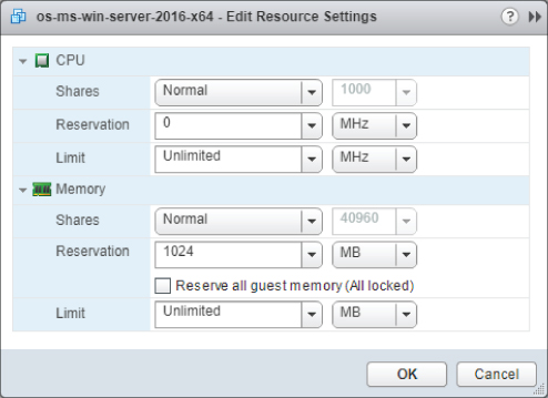
FIGURE 11.4 This memory reservation guarantees 1,024 MB of physical memory for the VM.
In this example, when the VM is powered on, the ESXi host must provide at least 1,024 MB of physical memory to support the VM's memory allocation. In fact, the VM is guaranteed 1,024 MB of physical memory. The host can provide the remaining 3,072 MB of memory from either physical memory or the VMkernel swap, as shown in Figure 11.5. Because a portion of the VM memory is guaranteed to be allocated directly from physical memory, ESXi reduces the size of the VMkernel swap file by the amount of the reservation. In this example, the VMkernel swap file is reduced in size by 1,024 MB to a total of 3,072 MB. This behavior is consistent with what you have seen so far: with a reservation of 0 MB, the VMkernel swap file is the same size as the amount of configured memory. As the reservation increases, the size of the VMkernel swap file subsequently decreases.
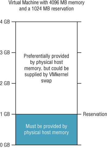
FIGURE 11.5 The memory reservation reduces the potential need for VMkernel swap space by the size of the reservation.
The behavior ensures that a VM has at least some physical memory available to it even if the ESXi host is running more VMs than it has actual physical memory to support, but there is a downside. If you assume that each of the powered-on VMs on the host has a 1,024 MB reservation, and you have 8 GB of available physical memory in the host, then you will only be able to concurrently power-on eight VMs (8 × 1,024 MB = 8,192 MB). On a more positive note, if each VM is configured with an initial allocation of 4,096 MB, then you are now capable of running VMs that would need 32 GB of memory on a host with only 8 GB. ESXi uses the technologies described previously—transparent page sharing, the balloon driver, memory compression, and VMkernel swap—to manage the allocation of more memory than is physically available on the host.
There is one additional side effect from using memory reservations. We previously discussed that using a memory reservation guarantees physical memory for the VM. This is true, but only as the guest OS in the VM requests memory. If you have a VM with a 1,024 MB reservation configured, then the ESXi host will allocate memory to the VM on an as-needed basis after the initial 1,024 MB of memory is allocated as part of the reservation. Memory is allocated on-demand; the presence of a reservation does not change this behavior. However, once the memory reservation is allocated, it is locked to the VM—it cannot be reclaimed via the balloon driver, and it will not be swapped out to disk or compressed.
On one hand, this is a good thing; it underscores the fact that the memory is guaranteed to this VM. On the other hand, it should be used carefully; once allocated to VM, reserved memory cannot be reclaimed for use by other VMs or the hypervisor.
Like all the mechanisms described in this chapter, use memory reservations carefully and with a full understanding of the impact on the behavior and operations of an ESXi host.
USING MEMORY LIMITS
If you refer to Figure 11.3 (which was shown earlier in this chapter), you will also see a setting for a memory limit. By default, all new VMs are created without a limit, which means the memory assigned during a VM's creation is its effective limit. So, what is the purpose of the memory limit setting? It sets the actual limit on how much physical memory may be used by that VM.
To see this behavior in action, we will change the limit on this VM from the default setting of Unlimited to 2,048 MB.
The effective result of the configuration change is as follows:
- The VM is configured with 4,096 MB of memory and the guest OS inside the VM has 4,096 MB available to use.
- The VM has a reservation of 1,024 MB of memory, which means that the ESXi host must allocate and guarantee 1,024 MB of physical memory to the VM.
- Assuming the ESXi host has enough physical memory available the hypervisor will allocate memory to the VM, as needed, up to 2,048 MB (the limit). Upon reaching 2,048 MB, the balloon driver inflates to prevent the guest OS from using more memory beyond the limit. When the memory demand on the guest OS drops below 2,048 MB, the balloon driver deflates and returns memory to the guest. The effective result of this behavior is that the memory the guest OS uses remains below 2,048 MB (the limit).
- The “memory gap” of 1,024 MB between the reservation and the limit may be provided by either physical host memory or the VMkernel swap space. As always, the ESXi hypervisor will allocate physical memory if available.
The key concern with the use of memory limits is that they are enforced without guest OS awareness. When a VM is configured with 4 GB, the guest OS will think it has 4 GB of memory with which to operate, and it will behave accordingly. By placing a 2 GB limit on this VM, the VMkernel will enforce the VM to only use 2 GB of memory, and it will do so without the knowledge or cooperation of the guest OS. The guest OS will continue to behave as if it has 4 GB of memory, unaware that a limit has been placed on it by the hypervisor. If the working set size of the guest OS and its applications exceeds the memory limit, setting a limit will degrade the performance of the VM because the guest OS will be forced to swap pages to disk (guest OS swapping; not hypervisor swapping).
Generally, memory limits should be a temporary stop-gap measure when you need to reduce physical memory usage on an ESXi host and when a negative impact to performance is an acceptable implication. Ideally, you would not want to overprovision a VM and then constrain the memory usage with a limit on a long-term basis. In this scenario, the VM will typically perform poorly and would perform better if configured with less memory and no limit.
When used together, an initial memory allocation, a memory reservation, and a memory limit, can be powerful techniques in efficiently managing the available memory on an ESXi host.
USING MEMORY SHARES
In Figure 11.3 (shown earlier in this chapter), there is a third setting labeled Shares that we have not yet discussed. The memory-reservation and memory-limit mechanisms help provide finer-grained controls over how ESXi should allocate memory to a VM. These mechanisms are always in use—that is, a Limit is enforced even if the ESXi host has plenty of physical memory available for a VM to use.
Memory shares perform quite differently. Shares are a proportional system that allows you to assign resource prioritization to VMs, but shares are used only when the ESXi host is experiencing physical memory contention—the VMs on a host are requesting more memory than the host can provide. If an ESXi host has plenty of memory available, shares do not play a role. However, when memory resources are scarce and the hypervisor needs to decide which VM should be given access to memory, shares establish a priority setting for a VM requesting memory that is greater than the reservation but less than the limit. Recall that memory under the reservation is guaranteed to the VM, and memory over the limit would not be allocated. Shares only affect the allocation of memory between the reservation and the limit.
In other words, if two VMs are requesting more memory than their reservation limit and more than the ESXi host can satisfy, share values can ensure that higher-priority access to the physical memory for one VM over the other.
While you could just increase the reservation for that VM, and it may be a valid technique, it may limit the total number of VMs that a host can run. Increasing the configured amount of memory may also require a reboot of the VM to become the effective allocation (unless the guest OS supports hot-add of memory and that feature has been enabled as described in Chapter 9), but shares can be dynamically adjusted while the VM is powered on.
Shares only come into play when an ESXi host cannot satisfy the requests for physical memory—contention. If an ESXi host has enough free physical memory to satisfy the allocation requests from the VMs, it does not need to prioritize those requests. It's only when an ESXi host does not have enough of a resource to go around that decisions are made on how the resource should be allocated.
For the sake of this discussion, assume you have two VMs—VM1 and VM2—each with a 1,024 MB reservation and a configured maximum of 4,096 MB, and both are running on an ESXi host with less than 2 GB of memory available to the VMs. If the VMs have an equal number of shares, such as 1,000 each (we will discuss values later), then as each VM requests memory above its reservation value, each will receive an equal quantity of memory from the ESXi host. Furthermore, because the host cannot supply all the memory to both VMs, each will swap equally to disk (VMkernel swap file). This assumes, of course, that ESXi cannot reclaim memory from other running VMs using the balloon driver or other memory-management technologies described earlier. If you change VM1's Shares setting to 2,000, then VM1 will have twice the shares VM2 has assigned to it. This means that when VM1 and VM2 are requesting the memory above their respective Reservation values, VM1 gets two memory pages for every one memory page that VM2 receives. If VM1 has more shares, VM1 has a higher-priority access to available memory in the host. Because VM1 has 2,000 out of 3,000 shares allocated, it will get 67%; VM2 has 1,000 out of 3,000 shares allocated and therefore gets only 33% percent. This creates the two-to-one behavior described previously. Each VM is allocated memory pages based on the proportion of the total number of shares allocated across all VMs. Figure 11.6 illustrates this behavior.
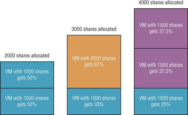
FIGURE 11.6 Shares establish relative priority based on the number of shares assigned out of the total shares allocated.
If you do not specifically assign shares to a VM, vSphere automatically assigns shares to a VM when it is created. Back in Figure 11.3, you can see the default Shares value is equal to 10 times the configured memory value when the memory allocation is expressed in terms of MB—more accurately, by default, 10 shares are granted to every MB assigned to a VM. The VM shown in Figure 11.3 has 4,096 MB of memory configured; therefore, its default memory Shares value is 40,960. This default allocation ensures that each VM is granted priority to memory on a measure that is directly proportional to the amount of memory configured for it.
As more and more VMs on an ESXi host are powered on, it gets more difficult to predict the actual memory utilization and the amount of access each VM gets. Later in this chapter, in the section “Using Resource Pools,” we will discuss more sophisticated methods of assigning memory limits, reservations, and shares to a group of VMs using resource pools.
We have discussed how VMware ESXi uses advanced memory management technologies, but there is another aspect that you must also consider: overhead. The next section provides information on the memory overhead figures when using ESXi.
EXAMINING MEMORY OVERHEAD
As the saying goes, “nothing is free,” and in the case of memory on an ESXi host, there is a cost. That cost is memory overhead. Several basic processes on an ESXi host will consume host memory. The VMkernel itself, various running hypervisor service daemons, and each powered on VM will result in the VMkernel allocating some memory to host each VM above the initial configured amount. The amount of physical memory allocated to power on each VM depends on the virtual CPU and memory configuration for each. VMware has improved the overhead requirements significantly over the last few vSphere releases. To give you an indication of what they are for version 6.7, see Table 11.1. The values have been rounded to the nearest whole number.
TABLE 11.1: Virtual machine memory overhead
Source: “Overhead Memory on Virtual Machines” - VMware vSphere 6.7 official documentation: https://docs.vmware.com/
| VIRTUAL MEMORY ASSIGNED (MB) | 1 VCPU | 2 VCPUS | 4 VCPUS | 8 VCPUS |
| 256 | 20 MB | 20 MB | 32 MB | 48 MB |
| 1,024 | 26 MB | 30 MB | 38 MB | 54 MB |
| 4,096 | 49 MB | 53 MB | 61 MB | 77 MB |
| 16,384 | 140 MB | 144 MB | 152 MB | 169 MB |
As you plan the allocation of memory to your VMs, be sure to refer to these memory-overhead figures and include the overhead values in your calculations for how memory will be assigned and used. This is especially essential if you plan on using several VMs with large amounts of memory and virtual CPUs. As you can see in Table 11.1, in this situation, the memory overhead required could become a substantial factor.
SUMMARIZING HOW RESERVATIONS, LIMITS, AND SHARES WORK WITH MEMORY
The behavior of reservations, limits, and shares is slightly different for each of the four key resources. Here's a quick review of their behavior when used for controlling memory allocation:
- Reservations guarantee memory for a specific VM. Memory is not allocated until it's requested by the VM, but an ESXi host must have enough free memory to satisfy the entire reservation before the VM can power on. Therefore, you cannot reserve more memory than the server has physically available. Once allocated to a VM, reserved memory is not swapped, nor is it reclaimed by the ESXi host. It is locked for that VM.
- Limits enforce an upper boundary on the use of memory. Limits are enforced using the VMware Tools balloon driver and—depending on the VM's working set size—could have a negative impact on performance. As the VM approaches the limit—of which the guest OS is unaware—the balloon driver will inflate to keep memory usage under the limit. This will result in the guest OS swapping to its disk, which will typically degrade performance.
- Shares apply only during periods of contention for the physical memory resources. They establish prioritized access to host memory. The VMs are prioritized based on a percentage of shares allocated versus total shares granted. During periods when the host is not experiencing memory contention, shares do not apply and will not affect memory allocation or usage.
A similar summary of the behavior of reservations, limits, and shares will be provided when they are used to control CPU usage, which is the topic of the next sections.
Managing Virtual Machine CPU Utilization
When creating a VM using the vSphere Web Client, you must configure two CPU-related fields. First, select how many virtual CPUs you want to allocate to the VM, and then assign the number of cores to those CPUs (see Figure 11.7). These CPU settings allow the VM's guest OS to use between 1 and 128 virtual CPUs from the ESXi host, depending on the guest OS and the vSphere edition license.
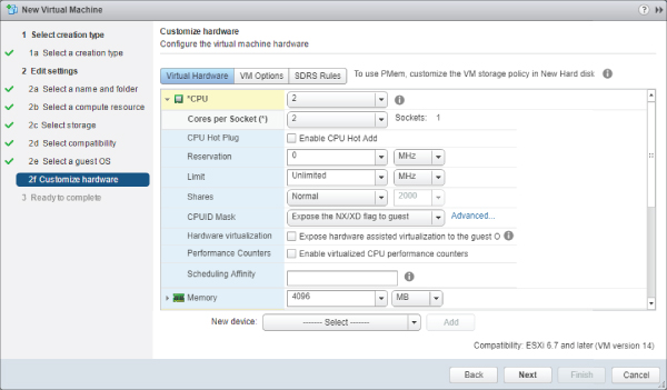
FIGURE 11.7 Both the number of sockets and number of cores per socket can be configured for VMs.
When VMware's engineers designed the hypervisor platform, they began with a real system board and used it to model the VM—in this case, it was based on the Intel 440BX chipset. The VM could emulate the PCI bus, which could be mapped to I/O devices through a standard interface, but how could a VM emulate a CPU?
The answer was “no emulation.”
Think about a virtual system board that has a CPU socket “hole” where the CPU is added—and the guest OS simply looks through the socket and sees one of the cores in the host server. This allowed the engineers to avoid writing CPU emulation software that could change each time chipset vendors introduced a new instruction set. If there was an emulation layer, it would also add significant overhead, which would reduce the hypervisor-platform performance by adding more computational overhead.
How many CPUs should a VM have? Assume a VM is replacing a legacy, physical DHCP server that runs at less than 10% CPU utilization at its busiest point in the day. Most certainly, it does not need more than one virtual CPU. In fact, if you configure the VM with two virtual CPUs (vCPUs), then you may limit the scalability of the entire host.
The VMkernel simultaneously schedules CPU cycles for multi-vCPU VMs. When a dual-vCPU VM places a request for CPU cycles, the request goes into a queue for the host to process, and the host must wait until there are at least two physical cores or hyperthreads (if hyperthreading is enabled) with concurrent idle cycles to schedule that VM. A relaxed co-scheduling algorithm provides a bit of flexibility in allowing the cores to be scheduled on a slightly skewed basis, but even so, it can be more difficult for the hypervisor to find open time slots across two cores. This occurs even if the VM needs only a few clock cycles to do a task that can be scheduled with only a single processor.
On the other hand, if a VM needs two vCPUs because of the application or service design it will be processing on a constant basis, then it makes sense to assign two vCPUs to that VM—but only if the host has four or more total CPU cores. If your ESXi host is an older-generation dual-processor single-core system, then assigning a VM two vCPUs will mean that it owns all the CPU processing power on that host every time it gets CPU cycles. You will find that the overall performance of the host and any other VMs will be less than ideal. Of course, in today's market of multicore CPUs, this consideration is less significant than it was in previous hardware generations.
Default CPU Allocation
Like the memory settings discussed previously, the Reservation, Limit, and Shares settings can be configured for CPU resources as well.
When a VM is created with a single vCPU, the total maximum CPU cycles for the VM are equal to the clock speed of the host system's core. In other words, if you create a new VM, it can see through the “hole in the system board,” and it sees whatever the core is in terms of clock cycles per second—an ESXi host with a 2.2 GHz CPU's 10-core processer in it will allow the VM to see one 2.2 GHz core.
Figure 11.8 shows the default settings for CPU Reservation, Limits, and Shares.

FIGURE 11.8 By default, vSphere provides no CPU reservation, no CPU limit, and 1,000 CPU shares.
Setting CPU Affinity
In addition to reservations, limits, and shares, vSphere offers a fourth option for managing CPU usage: CPU affinity. CPU affinity allows you to statically associate a VM to a specific physical CPU core. CPU affinity is generally not recommended; it has a list of rather significant drawbacks:
- CPU affinity prevents vMotion.
- The hypervisor is unable to load-balance the VM across all the processing cores in the server. This prevents the hypervisor's CPU scheduler from making efficient use of the host resources.
- Because vMotion is inhibited, you cannot use CPU affinities in a cluster where vSphere DRS isn't set to Manual operation.
Because of these limitations, most organizations avoid using CPU affinity. However, if, for example, you find that you need to use CPU affinity to adhere to licensing requirements or an extreme latency sensitive workload, you can configure your VM to use it.
Perform the following steps to configure CPU affinity:
- If vSphere Web Client is not already running, open a browser, connect to the vSphere Web Client on your vCenter Server instance, and log on.
- Navigate to either the Hosts And Clusters view or the VMs And Templates view.
- In the inventory, find the VM to edit.
- Select the VM and select the Edit Settings option from the Actions menu.
- On the Virtual Hardware tab, click the triangle next to CPU.
- In the Scheduling Affinity section, provide a list of the CPU cores this VM can access. For example, if you wanted the VM to run on cores 1 through 4, you could type 1–4.
- Click OK to save the changes.
Rather than using CPU affinity to guarantee CPU resources, consider using reservations.
Using CPU Reservations
As you saw in Figure 11.7, the default CPU reservation for a new VM is 0 MHz (no reservation). Recall that a reservation is a resource guarantee. By default, a VM is not guaranteed any CPU scheduling time by the VMkernel. When the VM has work to be done, it places its CPU request into the CPU queue, and the VMkernel schedules the request in sequence along with all of the other VM requests. On a lightly loaded ESXi host, it is unlikely the VM will wait long for CPU time; however, on a heavily loaded host, the time the VM may wait could be significant.
If you were to set a 1,024 MHz reservation, as shown in Figure 11.9, this would effectively ensure the amount of CPU available instantly to this VM when there is a need for CPU cycles.

FIGURE 11.9 A VM configured with a 1,024 MHz reservation for CPU activity is guaranteed that amount of CPU capacity.
A CPU reservation has a notable impact on the behavior of the ESXi host and, as such, CPU reservations and memory reservations behave identically. The ESXi host must satisfy the reservation by providing enough resources to meet the reservations. If each VM you create has a 1,024 MHz reservation and your host has 12,000 MHz of CPU capacity, you can power on no more than 11 VMs (1,024 MHz × 11 = 11,264 MHz), even if each machine is idle. Notice the term “power on” instead of “create” was used; resources are allocated only when a VM is powered on, not created.
Although a CPU reservation behaves like a memory reservation, a CPU reservation is very different from a memory reservation when it comes to “sharing” reserved CPU cycles. Recall from the previous section that once reserved memory is allocated to the VM, it is never reclaimed, paged out to disk, or shared in any way. The same is not true for CPU reservations.
Suppose you have two VMs, VM1 and VM2, and VM1 has a CPU reservation of 1,024 MHz and VM2 has no reservation. If VM1 is idle and not using its reserved CPU cycles, those cycles can be given to VM2. If VM1 suddenly needs cycles, VM2 doesn't get them anymore, and they are assigned to VM1.The Reservation setting on a CPU is similar using the Reservation setting for memory, but it is also very different.
Earlier, we discussed how using a Limit setting with memory had some significant drawbacks, but what about CPU limits? We will cover that next.
Using CPU Limits
In addition to CPU reservations, you can set a limit on the amount of CPU allocated. This effectively limits the ability of a VM to use a maximum number of clock cycles per second, regardless of what the host has available. Keep in mind that a VM with a single-core vCPU hosted on a 2.2 GHz, dual-socket, 10-core processor host will see only a single 2.2 GHz core as its maximum, but as an administrator, you could alter the limit to prevent the VM from using the maximum core speed. For instance, you could set a 500 MHz limit on the DHCP server so that when it re-indexes the DHCP database, it will not attempt to take all the 2.2 GHz on the processor core that it can see. The CPU limit allows you to throttle the VM down to use less processing power than is available on the physical core. Not every VM needs to have access to the entire processing capability of the physical processor core.
The key drawback to using a CPU Limit setting is its performance impact on the guest OS and the applications or services running on the VM. The Limit setting is a true limit; the VM will not be scheduled to run on a physical CPU core more than the limit specifies, even if there are plenty of CPU cycles available. It is important, therefore, to understand the CPU processing needs of your workloads before arbitrarily setting any CPU limits in order to avoid significantly impacting their performance.
Using CPU Shares
The shares model in vSphere, which lets you prioritize access to resources when resource contention occurs, behaves similarly for both memory and CPU. Shares of CPU determine how much CPU is provided to a VM in the face of contention with other VMs needing CPU activity. By default, all VMs begin with an equal number of shares, which means that if VMs compete for CPU cycles on an ESXi host, each is serviced with equal priority. Keep in mind that the share value only affects those CPU cycles that are greater than the reservation set for the VM, and the share value applies only when the ESXi host has more requests for CPU cycles than it has CPU cycles to allocate.
In other words, the VM is granted access to its reservation cycles regardless of what else is happening on the host, but if the VM needs more CPU cycles—and there is competition—then the share values come into play. If there is no CPU contention on the host, and it has enough CPU cycles to go around for all VMs, the CPU Shares value will not impact CPU allocations.
Several conditions must be met for shares to be considered for allocating CPU cycles. The best way to determine this is to consider several scenarios. For the scenarios we will cover, assume the following details about the environment:
- The ESXi host includes dual, single-core, 3 GHz CPUs.
- The ESXi host has one or more VMs, each configured with a single vCPU.
- Scenario 1 The ESXi host has a single VM powered on. The shares are set at the defaults for any running VMs. The Shares value will have no effect in this scenario because there is no competition between VMs for CPU time.
- Scenario 2 The ESXi host has two idle VMs powered on. The shares are set at the defaults for the VMs. The Shares values have no effect in this scenario; there is no competition between VMs for CPU time, because both are idle.
- Scenario 3 The ESXi host has two equally busy VMs powered on, and both are requesting maximum CPU capacity. The shares are set at the defaults for the VMs. Again, the Shares values have no effect in this scenario, because there is no competition between VMs for CPU time. In this scenario, each VM is serviced by a different core in the host.
- Scenario 4 To force contention, both VMs are configured to use the same physical CPU by setting the CPU affinity. The ESXi host has two equally busy VMs powered on, and both are requesting maximum CPU capacity. This ensures contention between the VMs. The shares are set at the defaults for the VMs. Will the Shares values have any effect in this scenario? Yes! Because all VMs have equal Shares values, each VM has equal access to the host CPU queue, so you do not see any effects from the Shares values.
- Scenario 5 The ESXi host has two equally busy VMs powered on, and both are requesting maximum CPU capacity with CPU affinity set to the same physical core. The shares are set as follows: VM1 is set to 2,000 CPU shares, and VM2 is set to the default 1,000 CPU shares. Will the Shares values have any effect in this scenario? Yes! VM1 has double the number of shares than what VM2 has. For every clock cycle that VM2 is assigned by the host, VM1 is assigned two clock cycles. Stated another way, out of every three clock cycles assigned to VMs by the ESXi host, two are assigned to VM1, and one is assigned to VM2. The diagram shown earlier in Figure 11.6 helps graphically reinforce how shares are allocated based on a percentage of the total number of shares assigned to all VMs.
- Scenario 6 The ESXi host has three equally busy VMs powered on, and each is requesting maximum CPU capabilities with CPU affinity set to the same physical core. The shares are set as follows: VM1 is set to 2,000 CPU shares, and VM2 and VM3 are set to the default 1,000 CPU shares. Will the Shares values have any effect in this scenario? Yes! VM1 has double the number of shares that VM2 and VM3 have assigned. This means that for every two clock cycles that VM1 is assigned by the host, VM2 and VM3 are each assigned a single clock cycle. Stated another way, out of every four clock cycles assigned to VMs by the ESXi host, two cycles are assigned to VM1, one is assigned to VM2, and one is assigned to VM3. You can see that this has effectively watered down VM1's CPU capabilities.
- Scenario 7 The ESXi host has three VMs powered on. VM1 is idle while VM2 and VM3 are equally busy, each VM is requesting maximum CPU capabilities, and all three VMs are set with the same CPU affinity. The shares are set as follows: VM1 is set to 2,000 CPU shares, and VM2 and VM3 are set to the default 1,000 CPU shares. The Shares values will still have an effect in this scenario. In this case, VM1 is idle, which means it is not requesting any CPU cycles; therefore, this means that VM1's Shares value is not considered when apportioning the host CPU to the active VMs. VM2 and VM3 would equally share the host CPU cycles because their shares are set to an equal value.
Given the preceding scenarios, if you were to extrapolate to a 10-core host with 30 or so VMs, it would be difficult to set Shares values on a VM-by-VM basis and to predict how the system will respond. The question then becomes, “Are shares a useful tool?”
The answer is yes, but in large enterprise environments, you must examine resource pools and the ability to set share parameters along with reservations and limits on collections of VMs. We will discuss resource pools in the upcoming “Using Resource Pools” section, after summarizing the behavior of reservations, limits, and shares when used to control CPU allocation and usage.
Summarizing How Reservations, Limits, and Shares Work with CPUs
The following list includes some key behaviors and facts surrounding the use of reservations, limits, and shares, when applied to controlling or modifying CPU usage:
- Reservations set on CPU cycles provide guaranteed processing power for VMs. Unlike memory, reserved CPU cycles can and will be used by ESXi to service other requests when needed. As with memory, the ESXi host must have enough real, physical CPU capacity to satisfy a reservation to power on a VM. Therefore, you cannot reserve more CPU cycles than the host can deliver.
- Limits on CPU usage simply prevent a VM from gaining access to additional CPU cycles even if CPU cycles are available to use. Even if the host has plenty of CPU processing power available to use, a VM with a CPU limit will not be permitted to use more CPU cycles than specified in the limit. Depending on the guest OS and the applications or services, this may or may not have an adverse effect on performance.
- Shares are used to determine CPU allocation when the ESXi host is experiencing CPU contention. Like memory, shares grant CPU access on a percentage basis calculated on the number of shares granted out of the total number of shares assigned. This means that the percentage of CPU cycles granted to a VM based on its Shares value is always relative to the number of other VMs and the total number of shares granted, and it is not an absolute value.
As you can see, there are some key differences as well as several similarities in how these mechanisms work for memory when compared to how they work for CPU.
We have discussed two of the four major resource types—memory and CPU. Before we can move on to the third resource type—networking—we need to discuss the concept of resource pools.
Using Resource Pools
The settings for VM resource allocation—memory and CPU reservations, limits, and shares—are methods that modify or control how resources are distributed to individual VMs or that modify the priority of VMs seeking access to resources.
In much the same logical way that you assign users to groups and then assign permissions to the groups, you can leverage resource pools to allocate resources to collections of VMs in a less tedious and more effective process. In other words, instead of configuring reservations, limits, or shares on a per-VM basis, you can use a resource pool to set those values on a group of VMs all at once.
A resource pool is a special type of container object, much like a folder, in the Hosts And Clusters view. You can create a resource pool on a standalone host or as a management object in a vSphere DRS-enabled cluster. Figure 11.10 shows the creation of a resource pool.

FIGURE 11.10 You can create resource pools on individual hosts and within clusters. A resource pool provides a management and performance configuration layer in the vCenter Server inventory.
If you examine the properties of the resource pool, you will see two sections: one for CPU settings and one for Memory settings, expressed as Shares, Reservation, and Limit. When you apply resource settings to a resource pool, those settings affect all the VMs found within that resource pool container object. This provides a scalable method to adjust the resource settings for groups of VMs. Setting CPU and memory shares, reservations, and limits on a resource pool is similar to setting the same values on individual VMs. The behavior of these values, however, can be quite different on a resource pool than on an individual VM.
To illustrate how to set reservations, limits, and shares on a resource pool, as well as to explain how these values work when applied to a resource pool, we will use an example vSphere cluster with two resource pools. The resource pools are named Production and Development. Figure 11.11 and Figure 11.12 show the values that have been configured for the Production and Development resource pools, respectively.
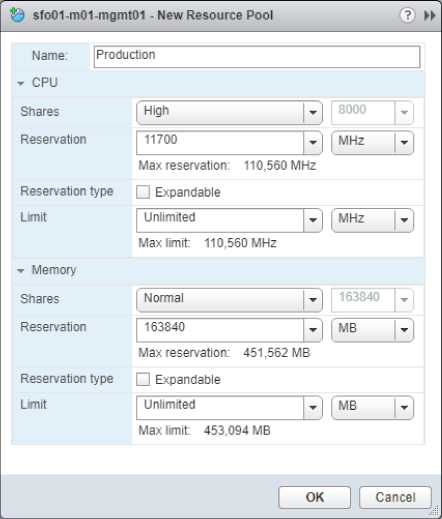
FIGURE 11.11 The Production resource pool is guaranteed CPU and memory resources and higher-priority access to resources in the face of contention.

FIGURE 11.12 The Development resource pool is configured for lower-priority access to CPU and memory in the event of resource contention.
Configuring Resource Pools
Before we discuss how resource pools behave with resource allocations, you must first create and configure the resource pools. Use the resource pools, shown earlier in Figure 11.11 and Figure 11.12, as examples for creating and configuring resource pools.
To create a resource pool, simply right-click either an individual ESXi host or a vSphere cluster, and select New Resource Pool. In the Create Resource Pool dialog box, you will need to supply a name for the new resource pool and set the CPU and Memory values as desired.
After creating the resource pool, simply move the VMs into it by clicking the VM in the inventory and dragging it onto the appropriate resource pool. The result is a hierarchy similar to the one that's shown in Figure 11.13.

FIGURE 11.13 VMs assigned to a resource pool consume resources allocated to the resource pool.
In this example, you have two classifications of servers—production and development—and you have created a resource pool for each classification. The goal is to ensure that if there is competition for a resource, the production VMs will be assigned higher-priority access to that resource. In addition to that goal, you need to ensure that the VMs in development cannot consume more than 24 GB of physical memory with their powered-on VMs. You do not care how many VMs run concurrently as part of the development group, only that they do not collectively consume more than 24 GB of physical memory. Finally, you need to guarantee that a minimum amount of resources is available for both groups.
To achieve your goal of guaranteeing resources for the production VMs, you will set the Production resource pool to use the following settings (refer to Figure 11.11):
- CPU resources area: Shares value of High.
- CPU resources area: Reservation value of 11,700 MHz.
- CPU resources area: Expandable check box Reservation Type is deselected.
- CPU resources area: No CPU limit (the Unlimited option in the Limit drop-down menu is selected).
- Memory resources area: Shares value of Normal.
- Memory resources area: Reservation value of 16,384 MB.
- Memory resources area: Expandable check box for Reservation Type is deselected.
- Memory resources area: No memory limit (the Unlimited option in the Limit drop-down menu is selected).
Similarly, you will apply the following settings to the development VMs in the Development resource pool (see Figure 11.12):
- CPU resources area: Shares value of Low.
- CPU resources area: Reservation value of 2,925 MHz.
- CPU resources area: Expandable check box for Reservation Type is deselected.
- CPU resources area: Limit value of 11,700 MHz.
- Memory resources area: Shares value of Low.
- Memory resources area: Reservation value of 4,096 MB.
- Memory resources area: Expandable check box for Reservation Type is deselected.
- Memory resources area: Limit value of 24,576 MB.
Setting these values on the resource pools involves right-clicking the resource pool, selecting Edit Settings, and then setting the required values.
Now that you have an example to work with, we will discuss what these settings will do to the VMs contained within each of the resource pools.
Understanding Resource Allocation with Resource Pools
In the previous section, you created two resource pools called Production and Development. The values for these resource pools are illustrated in Figure 11.11 and Figure 11.12. The goal behind creating these resource pools and setting the values on them was to ensure that a certain level of resources would always be available to production VMs—those found in the Production resource pool—and to limit the resources used by the development VMs—those found in the Development resource pool. In this example, you used all three values—Shares, Reservation, and Limit—to accomplish this goal. Next, we will review the behavior of each of these values when used on a resource pool.
MANAGING CPU USAGE WITH RESOURCE POOLS
First, we will examine the CPU Shares value assigned to the resource pools. As you saw in Figure 11.11, the CPU Shares value for the Production resource pool is set to High (8,000). Figure 11.12 shows that the Development CPU Shares value is set to Low (2,000). The impact of these two settings is similar to comparing the Shares values for CPU for two VMs—except in this case, if there is any competition for CPU resources between VMs in the Production and Development resource pools, the entire Production resource pool and all the VMs within the object have a higher priority. Figure 11.14 shows how this would break down with two VMs in each resource pool.

FIGURE 11.14 Two resource pools with different Shares values will be allocated resources proportional to their percentage of share ownership.
As you consider the details previously shown in Figure 11.13, keep in mind that the resource allocation occurs at each level. There are only two resource pools under the vSphere cluster, so the CPU is allocated 80/20 according to its Shares value. This means that the Production resource pool is allocated 80% of the CPU time, whereas, the Development resource pool receives only 20% of the CPU time.
Let's expand on Figure 11.13 and add the two VMs in each resource pool to get a more complete view of how Shares values work with a resource pool. In the resource pool, the CPU Shares values assigned to the VMs, if any, come into play. Figure 11.15 shows how this works.

FIGURE 11.15 The percentage of resources assigned to a resource pool via its Shares values is further subdivided according to the Shares values of the VMs within the pool.
In Figure 11.15, there are no custom CPU shares assigned to the VMs. Recall that each VM will therefore use the default value of 1,000 CPU shares. With two VMs in the resource pool, this means each VM receives 50% of the available CPU resources for the resource pool in which it is located, therefore each has 50% of the total number of shares assigned within the resource pool. In this example, 40% of the host CPU capacity will be allocated to each of the two VMs in the Production resource pool. If there were three VMs in each resource pool, then the CPU allocated to the parent resource pool would be split three ways. Similarly, if there were four VMs, then the CPU would be split four ways. You can verify this breakdown of resource allocation using the Monitor tab on the selected cluster, ESXi host, or resource pool. Figure 11.16 shows the Resource Reservation section for a cluster with the Production and Development resource pools. The CPU button is selected, meaning that the vSphere Web Client is showing you the breakdown of CPU allocation for the selected cluster.
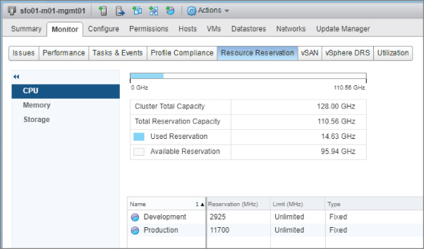
FIGURE 11.16 The Resource Reservation section of the Monitor tab can verify the allocation of resources to objects within the vCenter Server hierarchy.
Note that in the Figure 11.16 screenshot, both the resource pools and VMs are directly in the root of the cluster, which, for all intents and purposes, is a resource pool itself. In this case, the sum of all the Shares values—for both resource pools as well as VMs—is used to calculate the percentage of CPU allocated.
We now need to discuss an important consideration about the use of resource pools. It is possible to use resource pools as a form of inventory organization, as you would use VM folders. Some organizations and administrators have taken to using resource pools in this way to help keep the inventory organized in a specific fashion. Although this is possible, this approach is not recommended.
We will review the Resource Allocation section as seen in the HTML5-based vSphere Web Client. Although the HTML5 client is not covered in this book, the Flash-based vSphere Web Client no longer provides a view that presents the share. The view in the HTML5-based vSphere Web Client helps to illustrate why using resources pools merely for organization is not recommended.
Look at Figure 11.17, which shows the Resource Allocation section for a cluster of ESXi hosts. In the root of this cluster are 12 VMs assigned a total of 22,000 shares. Because each of these VMs is using the default CPU Shares value (1,000 shares per vCPU), they each get equal access to the host CPU capacity—in this case, 4.5% per vCPU (the VM with 2,000 shares and 9% shares has two vCPUs, and the VMs with 4,000 shares and 18% have four vCPUs).
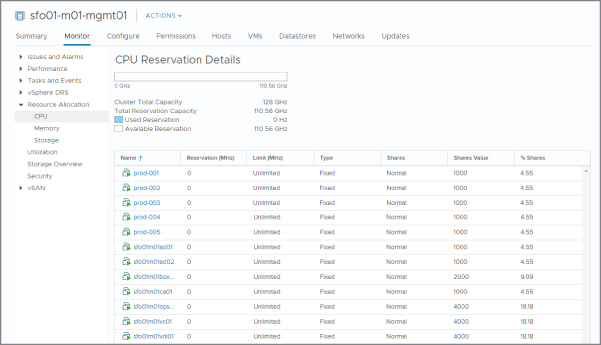
FIGURE 11.17 In the absence of custom CPU shares, CPU capacity is equally allocated to all VMs.
Now look at Figure 11.18. The only change here is that a “Production” resource pool has been added. No changes were made to any of the default values for the resource pool. The resource pool has a default CPU Shares value of 4,000. Note how the simple addition of this resource pool changes the default CPU allocation for the individual VMs by dropping it from 4.5% per vCPU to 3.8% per vCPU. The resource pool, on the other hand, now gets 15.3%. If you added a single VM with one vCPU to the resource pool, it would receive 15.3% of the CPU capacity, whereas other VMs would only receive 3.8% (or 7.6%percent for VMs with two vCPUs).

FIGURE 11.18 By default, the addition of a resource pool will alter the resource allocation policy even if you do not set any custom values.
It is for this reason—the change on the resource allocation distribution—that it is not recommended to use resource pools merely for the purposes of organizing the VM inventory. However, if you insist on using resource pools in this way, be sure you understand the impact of configuring your environment in this manner. A better way to organize your inventory, and one that will not impact the performance, is to use VMs' folders or vSphere tags; for more information, see Chapter 3, “Installing and Configuring vCenter Server.”
The next setting in the resource pool properties to evaluate is CPU Reservation for the CPU. Continuing with the examples shown earlier in Figure 11.11 and Figure 11.12, you can see a CPU Reservation value of 11,700 MHz has been set on the Production resource pool. The Development resource pool has a CPU Reservation value of 2,925 MHz.
Note that the four ESXi hosts in the cluster hosting the resource pools have two eight-core 2.00 GHz Intel Xeon CPUs each, so this scenario essentially reserves six cores for the Production resource pool and two cores for the Development resource pool. This setting ensures that at least 11,700 MHz of CPU time is available for all the VMs located in the Production resource pool, or 2,925 MHz of CPU for VMs in the Development resource pool.
If the four ESXi hosts in the cluster have a total of 128,000 MHz CPU (4 hosts × 16 cores × 2,000 MHz = 128,000 MHz), this means 116,300 MHz of CPU time is available on the cluster for other reservations. If one more resource pool was created with a Reservation value of 116,300 MHz, then all available host CPU capacity would be reserved. This configuration means you will not be able to create any additional resource pools or any individual VMs with Reservation values set. Remember that the ESXi host or cluster must have enough resource capacity—CPU capacity, in this case—to satisfy all reservations. You cannot reserve more capacity than the host has.
The CPU Reservation setting has the option to make the reservation expandable. An expandable reservation—which can be enabled by selecting the Expandable check box next to Reservation Type—allows a resource pool to “borrow” resources from its parent host or parent resource pool to satisfy reservations set on individual VMs within the resource pool. Note however, that resource pools with an expandable reservation “borrow” from the parent only to satisfy reservations, not to satisfy requests for resources that exceed what was originally specified in the reservations. Neither of the resource pools has expandable reservations, so you can assign only 5,850 MHz of CPU capacity as reservations to individual VMs within each resource pool. Any attempt to reserve more than this amount will result in an error message explaining that you have exceeded the allowed limit.
Deselecting the Expandable check box does not limit the total amount of CPU capacity available to the resource pool; it limits only the total amount of CPU capacity that can be reserved within the resource pool. To set an upper limit on actual CPU usage, you must use a CPU Limit setting.
CPU Limit is the third setting on each resource pool. The behavior of the CPU limit on a resource pool is akin to its behavior on individual VMs except, in this case, the limit applies to all VMs placed in the resource pool object. All VMs combined are allowed to consume up to this Limit value. In the example, the Production resource pool does not have a CPU limit assigned. In this case, the VMs in the Production resource pool are allowed to consume as many CPU cycles as the ESXi hosts in the cluster can provide. The Development resource pool, on the other hand, has a CPU Limit setting of 11,700 MHz. The result is that all the VMs in the Development resource pool are allowed to consume up to a maximum of 11,700 MHz of CPU capacity.
For the most part, CPU reservations, limits, and shares behave similarly on resource pools and on individual VMs. The same is also true for memory reservations, limits, and shares, as you will see in the next section.
MANAGING MEMORY USAGE WITH RESOURCE POOLS
In the memory portion of the resource pool settings, the first setting is the Shares value. This setting works in much the same way as memory shares works on individual VMs. It determines which group of VMs will be the first to release memory via the balloon driver—or if memory pressure is severe enough to activate memory compression or hypervisor swapping—in the face of contention. However, this setting specifies a priority value for all VMs in the resource pool when they compete for resources from other resource pools. Looking at the memory share settings in our example (Production = Normal and Development = Low), this means that if host memory is limited, VMs in the Development resource pool that need more memory than their reservation would have a lower priority than an equivalent VM in the Production resource pool. Figure 11.14, used earlier to help explain CPU shares on resource pool, applies here as well. As with CPU shares, you can also use the Resource Reservation section to view how memory resources are assigned to resource pools or VMs within resource pools.
The second setting is the resource pool's memory reservation. The memory Reservation value will reserve this amount of host memory for VMs in this resource pool, which effectively ensures that some physical memory is guaranteed to the VMs. As explained in the discussion on CPU reservations, the Expandable check box next to Reservation Type does not limit how much memory the resource pool can use, but rather how much memory you can reserve there.
With the memory Limit value, you set a limit on how much host memory a group of VMs can consume. If an administrative user has been added to a role with the Create VMs permission, the memory Limit value would prevent the administrator from powering on VMs that consume more than that amount of physical host memory. In our example, the memory Limit value on the Development resource pool is set to 24,576 MB. How many VMs can administrators in development create? As many as they wish.
Although this setting does nothing to limit the creation of VMs, it does place a limit on the powered-on VMs. So, how many can they run? The cap placed on memory use is not a per-VM setting but a cumulative setting. Administrators might be able to power on only one VM with all the memory or multiple VMs with lower memory configurations. If each VM is created without an individual memory Reservation value set, an administrator can operate as many concurrently powered-on VMs as they want. However, once the VMs consume 24,576 MB of host memory, the hypervisor will step in and prevent the VMs in the resource group from using any additional memory. Refer to our discussion of memory limits in the section “Using Memory Limits” for the techniques that the VMkernel uses to enforce the memory limit. If the administrator builds six VMs with 4,096 MB as the initial memory amount, then all four VMs will consume 24,576 MB (assuming no overhead, which we have already shown is not the case) and will run in physical memory. If an administrator tried to run 20 VMs configured for 2,048 MB of memory, then all 20 VMs will share the 24,576 MB of memory, even though their requirement is for 40,960 MB (20 × 2,048 MB)—the remaining amount of memory would most likely be provided by VMkernel swap. At this point, workload performance would be noticeably degraded.
If you want to clear a limit, select Unlimited from the Limit drop-down menu. This is true for both CPU limits as well as memory limits. By now, you should have a fair idea of how ESXi allocates resources to VMs as well as how you can tweak those settings to meet your specific demands and workloads.
As you can see, if you have groups of VMs with similar resource demands, using resource pools is a great way of ensuring consistent resource allocation. If you understand the hierarchical nature of resource pools—that resources are allocated first to the pool at its level in the hierarchy, and then the VMs in the resource pool—you should be able to effectively use resource pools.
As you have seen so far, you can control the use of CPU and memory; however, those are only two of the four core resources consumed by VM. In the next section, we will discuss how to control network traffic through network resource pools.
Regulating Network I/O Utilization
The resource pools we have discussed thus far only control CPU and memory usage. However, vSphere offers another type of resource pool, a network resource pool, which allows you to control and prioritize network utilization. Using network resource pools—to which you assign shares and limits—you can control incoming and outgoing network traffic. This feature is referred to as vSphere Network I/O Control or NIOC.
When you enable NIOC on a vSphere Distributed Switch (vDS), vSphere activates the following nine predefined network resource pools:
- Fault Tolerance (FT) Traffic
- Management Traffic
- NFS Traffic
- Virtual Machine Traffic
- vSAN Traffic
- iSCSI Traffic
- vMotion Traffic
- vSphere Data Protection Backup Traffic
- vSphere Replication (VR) Traffic
Each of these network resource pools is visible on the Resource Reservation section of a vDS, as you can see in Figure 11.19.
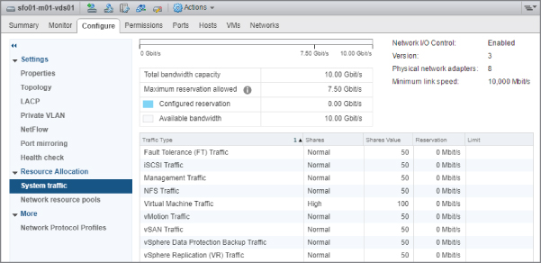
FIGURE 11.19 Network resource pools on a vDS provide granular control of network traffic.
Two steps are involved in setting up and using NIOC. First, you must enable NIOC on a vDS, and second, you must create and configure the network resource pools as necessary. The first of these steps is already complete if you create a vDS with a version set to 6.0.0 or higher, since NIOC is enabled by default.
Perform the following steps to enable NIOC on an existing vDS:
- If vSphere Web Client is not already running, open a browser, connect to the vSphere Web Client on your vCenter Server instance, and log on. Because NIOC relies on vDS, and vDS is available only with vCenter, NIOC cannot be used when connected directly to an ESXi host with the ESXi Host Client.
- Navigate to the Networking view using the navigation bar or the Home screen.
- Select the vDS for which you want to enable NIOC.
- Right-click the vDS.
- Click Edit and then Edit Settings.
- Select Enabled in the Network I/O Control drop-down menu, and then click OK.
This enables NIOC on the distributed switch. The Resource Allocation section of the vDS object will note that NIOC is enabled, as shown in Figure 11.20.
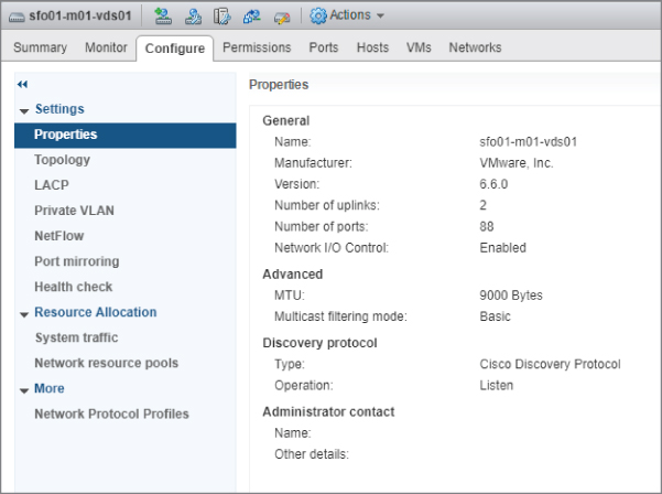
FIGURE 11.20 vCenter Server provides a clear indication that NIOC is enabled for a vDS.
In addition to enabling NIOC, you can modify the pre-defined network resource pools or create new resource pools, if you are using a vDS version 6.0.0 or above.
A network resource pool consists of three settings:
- The first value is Shares. Like the shares you used to prioritize access to CPU or memory when there was contention, physical adapter shares in a network resource pool establish priority for access to the physical network adapters when network contention exists. As with other types of shares, this value does not apply when no contention exists.
This value can be set to one of three predefined values, or you can set a custom value of up to 100. For the predefined values, Low translates to 25 shares, Normal equates to 50 shares, and High equals 100 shares.
- The second value is Reservation. This value guarantees an amount of bandwidth (in Mbps) to the network resource pool.
- The final value is Limit. This value specifies an upper limit on the amount of network traffic (in Mbps) that the network resource pool may consume. Leaving Unlimited selected means that only the physical adapters can limit the network resource pool.
Figure 11.21 shows all three of the values for the predefined Fault Tolerance (FT) Traffic network resource pool.
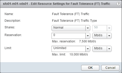
FIGURE 11.21 vSphere allows you to modify the predefined network resource pools.
You have the option of editing the predefined network resource pools or creating your own network resource pools. Perform the following steps to edit an existing network resource pool:
- If vSphere Web Client is not already running, open a browser, connect to vSphere Web Client on your vCenter Server instance, and then log on.
- Navigate to the Networking view.
- Select the vDS that contains the network resource pool you want to modify.
- Click the Resource Allocation section and ensure that you are on the System Traffic page.
- Select the network resource pool you want to edit and click the Edit (pencil) icon.
- In the Network Resource Pool Settings dialog box, modify the Shares, Reservation, and Limits settings as desired.
- Click OK to save the changes to the network resource pool.
You might prefer to leave the predefined network resource pools intact and create your own.
Follow these steps to create a new network resource pool:
- If vSphere Web Client is not already running, open a browser, connect to vSphere Web Client on your vCenter Server instance, and log on.
- Navigate to the Networking view.
- Select the vDS on which you want to create the new network resource pool.
- Click the Configure tab, and then click the Resource Allocation section.
- Select Network Resource Pools; then click the Create a Network Resource Pool plus icon. The New Network Resource Pool dialog box appears (Figure 11.22).

FIGURE 11.22 You have the option of creating new network resource pools for custom network traffic control. - Supply a name and description for the new network resource pool.
- Define a reservation quota in Mbps or Gbps.
- Click OK to create the new network resource pool with the values you specified.
After you have at least one user-defined network resource pool, you can map port groups to the network resource pool.
Follow these steps to assign a port group to a user-defined network resource pool:
- If vSphere Web Client is not already running, open a browser, connect the vSphere Web Client on your vCenter Server instance, and log on.
- Navigate to the Networking view.
- Select the vDS that hosts the network resource pool you would like to map to a port group.
- Right-click the distributed port group you wish to map and select Edit Settings.
- In the settings, select the appropriate network resource pool, as shown in Figure 11.23.
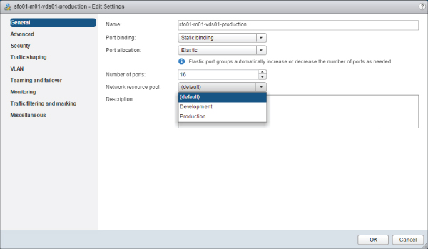
FIGURE 11.23 Users can map a distributed port group to any user-defined network resource pool, and multiple distributed port groups can be associated to a single network resource pool. - Click OK to save the changes and return to the Resource Allocation section.
In large environments with many distributed port groups, it may be tedious to determine which port groups are mapped to which network resource pools. To help ease this administrative burden, vCenter Server offers an easy way to show all the port groups linked to a specific network resource pool. With a network resource pool selected, click the Distributed Port Groups tab near the bottom of the screen. The view will switch to show you the specific port groups associated with the selected network resource pool. You can see this in Figure 11.24, which shows the port groups associated with the user-defined network resource pool named Production. You will also notice networking-specific details—such as VLAN ID, port binding, and the number of attached VMs—are shown in this view.

FIGURE 11.24 The vSphere Web Client provides a consolidated view of all the distributed port groups associated with a network resource pool.
NIOC offers a powerful way to help ensure that all the various types of converged network traffic present in a vSphere environment will coexist properly, especially as organizations move to (or beyond) 10 Gbe Ethernet. Fewer faster connections means more consolidated traffic and therefore a greater need to control how that traffic coexists on the same physical medium.
We have discussed three of the four core resources and demonstrated how vSphere manages the use of and access to each. Only one resource remains: storage.
Controlling Storage I/O Utilization
For vSphere, controlling memory or CPU allocation and utilization is relatively easy. The hypervisor determines how busy the CPU is and whether physical memory has been depleted. When resource contention occurs for either of these resources, not only is it easy to detect, but it is also easy to correct. If the CPU is too busy and there are not enough CPU cycles to go around, then you do not schedule cycles for lower-priority VMs—instead, you assign more cycles to higher-priority VMs.
How is this priority determined? Recall that Shares values are the mechanism that vSphere uses to determine the priority. Likewise, if memory becomes constrained, the balloon driver is inflated in the VMs' guest OS. It then reclaims some memory or slows down the rate of allocation to lower-priority VMs and increases the rate of allocation to higher-priority VMs. Not only does the hypervisor have complete visibility into the utilization of these resources, it also has complete control over the resources. Nothing gets scheduled on the CPU without going through the hypervisor, and nothing gets stored in memory without the hypervisor knowing about it. This complete control is what enables vSphere to offer shares as a way of establishing priority and offer reservations (guaranteed access to resources) and limits (caps on the usage of a resource). You learned about these mechanisms earlier in this chapter.
Network utilization begins to change the approach a little. The hypervisor has some visibility into the network; it can see how many Mbps are being generated and by which VMs. However, the hypervisor does not have complete control over network utilization. It can control inbound and outbound traffic, but it cannot control traffic generated somewhere else in the network. vSphere provides shares (to establish priority) and limits (to enforce a cap on the amount of network bandwidth a VM can consume). This is Network I/O Control, which we discussed in the previous section.
In many ways, resource allocation and utilization for storage is similar to networking. Other workloads are likely to be present on the shared storage (non-vSAN) vSphere requires for so many features. These other workloads will be external to vSphere and cannot be controlled or influenced in any way. Therefore, vSphere does not have complete control over the resource. Generally, the hypervisor also will not have as much visibility into the storage as it does with CPU and memory. As such, it is more difficult to detect and adjust storage resources. However, there are two metrics that vSphere can use to help determine storage utilization. The first is latency, and the second is peak throughput. Using one of these two metrics to detect contention, vSphere can offer shares (to establish priority when contention occurs) as well as limits (to ensure that a VM does not consume more than its fair share of storage resources). The feature that enables this functionality is called Storage I/O Control or SIOC.
Longtime users of vSphere are typically aware that the ability to assign Shares values to disks has been around for quite some time. The difference between that functionality and what SIOC offers is a matter of scope. Without SIOC, enabling shares on a VM virtual disk(s) is only effective for that specific host; the hosts in a cluster did not exchange information about how many shares each VM was allocated or how many shares were assigned in total. This made it virtually impossible to properly align the Shares values with the correct ratios of access to storage resources across multiple hosts.
SIOC addresses this by extending shares assignments across all hosts accessing a designated datastore. By using vCenter Server as its central information store, SIOC combines all the assigned shares across all the VMs on all the hosts and allocates storage I/O resources in the proper ratios according to the shares assignment. To make this work, SIOC has a few requirements that must be met:
- All datastores that are SIOC-enabled must be managed under a single vCenter Server instance. vCenter Server is the “central clearinghouse” for all the shares assignments.
- SIOC is supported on VMFS datastores connected via Fibre Channel (including FCoE) and iSCSI. NFS datastores are also supported. Raw device mappings (RDMs) are not supported.
- Datastores must have only a single extent. Datastores with multiple extents are not supported.
Assuming your environment meets the requirements, you can take advantage of SIOC. Configuring SIOC is a two-step process. First, enable SIOC on one or more datastores. Then, assign shares or limits to storage I/O resources on individual VMs.
Next, we will look at how to enable SIOC a designated datastore.
Enabling Storage I/O Control
SIOC is enabled on a per-datastore basis. By default, SIOC is disabled for a datastore, meaning that you must explicitly enable SIOC to take advantage of its functionality.
Perform the following steps to enable SIOC for a datastore:
- If vSphere Web Client is not already running, open a browser, connect the vSphere Web Client on your vCenter Server instance, and log on.
SIOC is available only when connected to vCenter Server, not when you are connected to an individual ESXi host with the ESXi Host Client.
- Navigate to the Storage view.
- Select the datastore for which you want to enable SIOC.
- Click the Configure tab.
- Under the Datastore Capabilities section on the General page, select Edit (Figure 11.25).
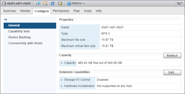
FIGURE 11.25 This dialog box allows you to manage the SIOC configuration of a specific datastore. - In the Datastore Capabilities dialog box, select the check box next to Enable Storage I/O Control.
- Click OK.
SIOC is now enabled for the selected datastore; this is reflected in the Datastore Capabilities section of the vSphere Web Client in the Configure tab, as you can see in Figure 11.26.

FIGURE 11.26 The status of SIOC for a datastore is displayed in the vSphere Web Client.
Generally, enabling SIOC using these steps is all you need to do to get started using SIOC and control use of storage I/O resources. However, in some cases, you may need to adjust the configuration of SIOC to ensure it functions properly for a specific vendor array and array configuration. Previously in this section, we discussed the two metrics in vSphere that can be used to detect contention: latency and peak throughput.
SIOC can use latency as the threshold to determine when it should activate and enforce Shares values for access to storage I/O resources. Specifically, when vSphere detects latency above a specific threshold value (measured in milliseconds), SIOC is activated. Because of the vast differences in array architectures and array performance, VMware recognized that users may need to adjust the default congestion threshold value for SIOC. After all, a specific latency measurement may indicate congestion (or contention) on some arrays and configurations but not on others. By making the congestion threshold adjustable, this allows vSphere administrators to fine-tune the behavior of SIOC to best match an array and its required configuration.
The other metric is the one that is enabled by default in vSphere 6.0: Peak Throughput. SIOC uses a tool called the IO Injector to test the characteristics of a storage array and perform two main checks. The first check is for overlaps in the underlying disk system of a datastore; this allows Storage DRS to make correct placement decisions for workload balancing, which is explained more in Chapter 12. The other check performed by the IO Injector—more relevant to this section—is the Peak Throughput check. Unlike checking for latency spikes, knowing the maximum capability of a specific datastore ensures that SIOC kicks in before congestion (or contention) occurs. Just like latency, you can adjust this threshold with a percentage setting.
Perform the following steps to adjust the congestion threshold setting for SIOC on a datastore:
- If vSphere Web Client is not already running, open a browser, connect the vSphere Web Client on your vCenter Server instance, and then log on.
- Navigate to the Storage view.
- Select the desired datastore from the inventory tree.
- Select the datastore for which you want to enable SIOC.
- Click the Configure tab.
- Under the Datastore Capabilities section on the General page, select Edit.
The Configure Storage I/O Control dialog box appears.
- Enter the desired congestion threshold setting, as a percentage or in milliseconds, and then click OK.
Once you have enabled SIOC on one or more datastores and you have (optionally) adjusted the congestion threshold per the storage vendor recommended values, you can start setting storage I/O resource values on your VMs.
Configuring Storage Resource Settings for a Virtual Machine
SIOC provides two mechanisms for controlling the use of storage I/O by VMs: shares and limits. These mechanisms operate in the same way here as with other resources; the Shares value establishes a relative priority as a ratio of the total number of shares assigned, and the Limit value defines the upper ceiling on the number of I/O operations per second (IOPS) that a VM may generate. As with memory, CPU, and network I/O, vSphere provides default settings for disk shares and limits. By default, every VM you create is assigned 1,000 disk shares per virtual disk and no IOPS limits.
If you need settings different from the default values, you can easily modify either the assigned storage I/O shares or the assigned storage I/O limit.
ASSIGNING STORAGE I/O SHARES
You modify the default storage I/O Shares value, open the Edit Settings for a VM, as you would when modifying memory and CPU allocation. Figure 11.27 shows the disk shares for a VM.

FIGURE 11.27 Storage I/O shares are not available in the Edit Resource Settings page of a VM. They need to be modified in the Edit Settings dialog box.
Perform the following steps to modify the storage I/O Shares value for a VM:
- If vSphere Web Client is not already running, open a browser, connect the vSphere Web Client on your vCenter Server instance, and log on.
- Navigate to either the Hosts And Clusters view or the VMs And Templates view.
- Right-click the VM on which you would like to change the storage I/O settings, and select Edit Settings from Actions menu..
- Click the triangle next to the hard disk. This displays the dialog box shown previously in Figure 11.27.
- For each virtual disk, click the Shares drop-down menu to change the setting from Normal to Low, High, or Custom, as shown in Figure 11.28.
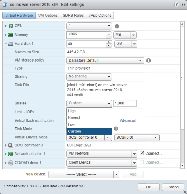
FIGURE 11.28 You must change the setting to Custom if you want to assign a specific storage I/O Shares value. - If you selected Custom in step 5, modify the storage I/O Shares value.
- Repeat steps 4, 5, and 6 for each virtual disk attached to the VM.
- Click OK to save the changes and return to the vSphere Web Client.
The selected virtual disks attached to the VM will now receive a proportional allocation of storage I/O resources based on the Shares value whenever SIOC detects contention (or congestion) on the datastore. Keep in mind that vSphere can use latency or peak bandwidth, as specified in the congestion threshold described earlier, as the trigger for activating SIOC. As with all other Shares values, SIOC enforces Shares values only when contention for storage I/O resources is detected. If there is no contention—as indicated by low latency or bandwidth values for that datastore or datastore cluster—then SIOC will not be activated.
CONFIGURING STORAGE I/O LIMITS
You can also set a limit on the number of IOPS that a VM may generate. By default, this value is unlimited. However, if you feel that you need to set an IOPS limit, you can set it in the same place as you would set storage I/O shares.
Perform these steps to set a storage I/O limit on IOPS:
- If vSphere Web Client is not already running, open a browser, connect the vSphere Web Client on your vCenter Server instance, and log on.
- Navigate to either the Hosts And Clusters view or the VMs And Templates view.
- Right-click the VM on which you would like to change the storage I/O settings, and select Edit Settings from the actions.
- Click the triangle next to the hard disk on which you would like to set an IOPS limit.
- Click in the Limit – IOPs drop-down option, and type in a value for the maximum number of IOPS that this VM will be allowed to generate against this virtual disk.
- Repeat steps 4 and 5 for each virtual disk attached to the VM.
- Click OK to save the changes and return to the vSphere Web Client.
Like the limits you apply to memory, CPU, or network I/O, the storage I/O limits are absolute values. The hypervisor will enforce the assigned storage I/O limit, even when there is plenty of storage I/O available.
Setting storage I/O resource values on a per-VM basis is fine, but what about when you need to have a consolidated view of what settings have been applied to all the VMs on a datastore? The vSphere Web Client provides a way to easily see a summary of these settings.
VIEWING STORAGE I/O RESOURCE SETTINGS FOR VIRTUAL MACHINES
In the Datastores And Datastore Clusters view, you can view a list of all the datastores managed by a vCenter Server instance. You enabled SIOC from this view previously, in the section “Enabling Storage I/O Control,” and here you can review the consolidated view of all the storage I/O settings applied to the VMs on a datastore.
On the VMs tab of a selected datastore in the Datastores And Datastore Clusters view, the vSphere Web Client provides a list of all the VMs resident on a datastore. If you scroll to the right using the scroll bar at the bottom of the vSphere Web Client window, you will see three SIOC-specific columns:
- Shares Value
- Limit – IOPs
- Datastore % Shares
Figure 11.29 shows these three columns on a datastore for which SIOC has been enabled. Note that the default values for the VMs on the selected SIOC-enabled datastore have not been modified.

FIGURE 11.29 The Virtual Machines view under the VMs tab of a datastore provides a useful summary view of storage-related information for all the VMs on that datastore.
As you can see in Figure 11.29, vCenter Server has used the assigned Shares values to establish relative percentages of access to storage I/O resources in the event of contention. This consistent behavior makes the task of managing resource allocation a bit easier for vSphere administrators.
Thus far, we have discussed shared storage where the features and settings are all array agnostic—Fibre Channel, iSCSI, or NFS. It does not matter how it is presented to your ESXi hosts. In the next section, we will discuss some features that are used solely with local flash-based storage.
Using Flash Storage
As physical-to-virtual ratios increase, and environments become denser, the need for faster storage grows. Flash storage has quickly become an industry standard and many servers and arrays ship with flash-based storage. Traditionally, storage arrays have used smaller portions of flash storage as caches to increase the response times to slower spindles, but as their sizes increase, so has the need for flash cache. Depending on the scenario, a more cost-effective solution can be to provision rackmount or blade servers with local flash storage.
vSphere offers two ways of using local flash-based host storage. vSphere Flash Read Cache is a feature that acts as a buffer for I/O on a per-VM basis. The other feature, Swap to Host Cache, is used to allocate local flash disks as swap space. These features are not mutually exclusive; they can be enabled at the same time and can even be backed by the same device, but they work in completely different ways.
ENABLING VSPHERE FLASH READ CACHE FOR VIRTUAL MACHINES
vSphere Flash Read Cache (or simply flash cache) can be allocated on a per-VM basis just like CPU or memory. In fact, it can be allocated down to an individual virtual disk (VMDK) level. However, a VM does not need to have flash cache allocated to function. Just like CPU and Memory allocations, no flash cache resources are consumed and the contents of the VM cache are flushed when the VM is powered off. Also, like CPU and Memory allocation, provided you have enough resources configured on each host in a cluster, flash cache is compatible with vSphere HA and vMotion, and therefore vSphere DRS.
The following steps outline how to enable vSphere Flash Read Cache:
- If vSphere Web Client is not already running, open a browser, connect the vSphere Web Client on your vCenter Server instance, and then log on.
- Navigate to the Hosts And Clusters view.
- Select a host from the Inventory tab.
- With a host selected, click the Configure tab. Then select the Virtual Flash Resource Management page under the Virtual Flash section.
- Click the Add Capacity button in the top-right corner of the content area.
- Select the SSD from the list, as shown in Figure 11.30. Click OK to close the dialog box. The SSD is now allocated to the flash resource pool.

FIGURE 11.30 You can add local SSDs to the flash resource capacity. - Navigate to the VM in the inventory that you wish to allocate flash cache resources to, select the Actions drop-down menu, and click Edit Settings.
- In the Edit Settings dialog box, expand the Hard Disk area of the VM properties. In the Virtual Flash Read Cache, allocate an amount of desired resources in GB or MB, as shown in Figure 11.31.
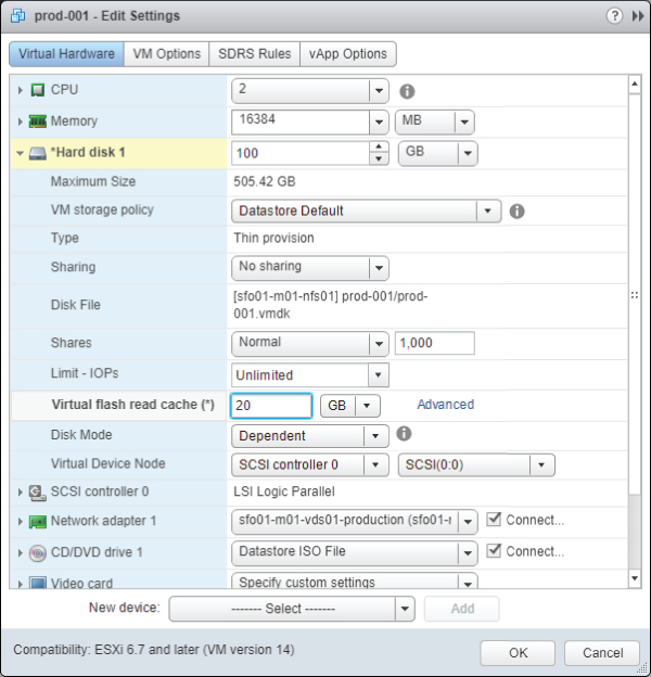
FIGURE 11.31 Allocating flash cache to a VM is as easy as allocating it as you would CPU or memory. - Click OK to close the dialog box and commit the configuration change to the VM.
As you can see, configuring and allocating flash cache is a simple task. However, it will not be so simple to determine which VM hard disks will benefit from allocating flash cache and how much to allocate. Chapter 13, “Monitoring VMware vSphere Performance,” discusses monitoring vSphere Performance in detail. The use of performance graphs and resxtop
CONFIGURING SWAP TO HOST CACHE
Swap to Host Cache is a feature that allocates a portion of local flash storage to be the location of a VM swap file. As discussed earlier in this chapter, the VM swap file is very different from the guest OS swap/page file.
An important point to note: this feature is beneficial only within environments that have memory contention to the point that the hypervisor must swap unreserved VM memory to disk. Based on the figures explained earlier in this chapter, accessing memory swapped to disk (even SSD) is still significantly slower than accessing it from memory. However, if your environment fits within this category, you will realize significant performance benefits by enabling the Swap to Host Cache feature.
To configure a host for Swap to Cache, a VMFS datastore that has been identified as being backed by a flash needs to be present. The following steps outline how to enable this feature:
- If vSphere Web Client is not already running, open a browser, connect the vSphere Web Client on your vCenter Server instance, and then log on.
- Navigate to the Hosts And Clusters view.
- Select a host from the Inventory tab.
- Click the Configure tab.
- Select Host Cache Configuration as shown in Figure 11.32.
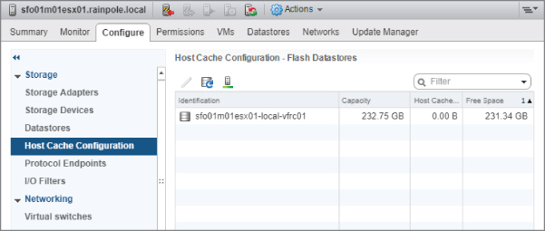
FIGURE 11.32 The Host Cache Configuration feature is designed specifically for flash-based datastores. - Highlight the appropriate flash-backed VMFS datastore and click the Edit pencil icon.
- Ensure the Allocate Space For Host Cache option is checked. A custom size may be provided if you would like to use this datastore for other purposes.
- Click OK to complete the configuration.
Once the Swap to Host Cache feature is enabled, the host proceeds to fill the allocated size on the datastore with .vswp.vswp
Throughout this chapter, we have discussed how you can use reservations, shares, and limits to modify the resource allocation and resource utilization behaviors of vSphere. In the next chapter, we will discuss some additional capabilities for balancing resource utilization across groups of servers.
The Bottom Line
- Manage virtual machine memory allocation. In almost every modern virtualized datacenter, memory is the resource that typically comes under contention first. Most organizations run out of memory on their ESXi hosts before other resources become constrained. Fortunately, vSphere offers advanced memory management technologies as well as extensive controls for managing the allocation of memory and utilization of memory by VMs.
- Master It To guarantee levels of performance, your IT Director believes that all VMs must be configured with at least 8 GB of memory. However, you know that many of your applications rarely use this much memory. What might be an acceptable compromise to help ensure performance?
- Master It You are configuring a new large-scale virtual desktop infrastructure environment, but you are worried that the cluster hosts will not have enough memory to handle the expected load. Which advanced memory management technique will ensure that your virtual desktops have enough memory without having to use the swap file?
- Manage CPU utilization. In a vSphere environment, the ESXi hosts control VM access to physical CPUs. To effectively manage and scale vSphere, you must understand how to allocate CPU resources to VMs, including how to use reservations, limits, and shares. Shares help adjust the allocation of resources in a constrained environment, reservations provide guarantees to resources, and limits provide a cap on resource usage.
- Master It A fellow vSphere administrator is concerned about the use of CPU reservations. She is worried that using CPU reservations will “strand” CPU resources, preventing those reserved but unused resources from being used by other VMs. Are the concerns of the administrator well founded?
-
Create and manage resource pools. Managing resource allocation and usage for large numbers of VMs can create an administrative overhead. Resource pools provide a mechanism for administrators to apply resource allocation policies to groups of VMs at the same time. Resource pools use shares, reservations, and limits to control and modify resource allocation behavior, but only for memory and CPU.
- Master It Your organization runs both development workloads and production workloads on the same hardware. How can you help ensure that development workloads do not consume too many resources and impact the performance of production workloads?
- Control network and storage I/O utilization. Memory, CPU, network I/O, and storage I/O make up the four major resource types that vSphere administrators must effectively manage for an efficient virtualized datacenter. By applying controls to network I/O and storage I/O, you can help ensure consistent performance, meet service-level objectives, and prevent one workload from unnecessarily consuming resources at the expense of other workloads.
- Master It Name two limitations of Network I/O Control.
- Master It What are the requirements for using Storage I/O Control?