
Now that we’ve had a tutorial of how to design, wire, and implement a MicroPython project, let’s now look at a more advanced project. In this case, we will use some very basic components to learn further how to work with hardware. The hardware of choice for this project will be LEDs, resistors, and a button. A button is the most basic of sensors. That is, when the button is pressed, we can make our MicroPython code respond to that action.
Working with LEDs is perhaps more of a “Hello, World!” style project for hardware because turning LEDs on and off is easy and except for figuring out what size of current limiting resistor is needed, wiring LEDs is also easy. Like most LED-based projects, we will be implementing a simulation. More specifically, we will implement a traffic light and a pedestrian walk button. The walk button is a button that pedestrians can use to trigger the traffic signal to change and stop traffic so they can cross the street.
Simulation projects can be a lot of fun because we already have an idea of how it should work and we are simulating something we have encountered. For example, unless you’ve lived in a very rural area, you most likely have encountered a traffic signal at an intersection that included walk/don’t walk signs with a button. If you live in the city, you will have encountered these in various configurations. When a pedestrian (or bicyclist) presses the walk button, the traffic lights all cycle to red and the walk sign is illuminated. After some time (30 seconds or so), the walk sign flashes and then about 15 seconds later, the walk signal cycles to don’t walk and the traffic signals resume their normal cycle.
Note
The word “cycle” refers to a set of states that are linear in action. Thus, cycle refers to the changing of one state to another.
We will also add a new twist to the traffic light simulation concept. We will use a web page to trigger the walk request. But first, we will learn how to wire and code the LED lights and add the web interface in a second step.
Overview
In this chapter, we will implement a traffic signal with a pedestrian walk button. This project works with LEDs, which allows us to see the state of our code as it executes. For the traffic light (also called a stoplight), we will use a red, yellow, and green LED to match the same colored lights on the traffic light. We will also use a red and yellow LED to correspond to the don’t walk (red) and walk (yellow) lights.
We will use a pushbutton (also called a momentary button) because it triggers (is on) only when pushed. When released, it is no longer triggered (is off). Trigger is the word used to describe the state of the button where triggered means the connections from one side of the button to another are connected (on). A button that remains triggered (latched) is called a latching button, which typically must be pressed again to turn off.
We will simulate the traffic light and walk signal by first turning on only the green traffic light LED and the red walk LED signal. This is the normal state we will use. When the button is pressed, the traffic light will cycle to yellow for a few seconds then cycle to red. After a few seconds, the walk signal will cycle to yellow and after a few seconds will begin flashing. After a few more seconds, the walk signal will cycle back to red and the traffic light to green.
To make things even more interesting, we will also see how to modify this project to use a button simulated from a web page. Yes, we will see how to remotely control the hardware and our code over the network. If you are using the Pyboard or another MicroPython board that does not have any networking capabilities, you will need a network module. We will revisit networking for the Pyboard as we develop the project.
Now let’s see what components are needed for this project and then we will see how to wire everything together.
Required Components
Table 9-1 lists the components you will need. You can purchase the components separately from Adafruit (adafruit.com), Sparkfun (sparkfun.com), or any electronics store that carries electronic components. Links to vendors are provided should you want to purchase the components. When listing multiple rows of the same object, you can choose one or the other - you do not need both. Also, you may find other vendors that sell the components. You should shop around to find the best deal. Costs shown are estimates and do not include any shipping costs.
Table 9-1. Required Components
Component | Qty | Description | Cost | Links |
|---|---|---|---|---|
MicroPython board | 1 | Pyboard v1.1 with headers | $45-50 | https://www.adafruit.com/product/2390 https://www.adafruit.com/product/3499 |
WiPy | $25 | |||
LED | 2 | Red LEDs | kit | |
LED | 2 | Yellow LEDs | kit | |
LED | 1 | Green LEDs | kit | |
Resistor | 5 | 220 or 330 ohm resistors | $8-12 | |
Button | 1 | Momentary button, breadboard friendly | kit | |
Breadboard | 1 | Prototyping board, half-sized | $5 | |
Networking Module (Pyboard) | 1 | CC3000 breakout board (or equivalent) | $15+ | various |
Jumper wires (WiPy) | 9 | M/M jumper wires, 6” (cost is for a set of 10 jumper wires) | $4 | |
Jumper wires (Pyboard) | 17 | M/M jumper wires, 6” (cost is for a set of 10 jumper wires) | $4 | |
Power | 1 | USB cable to get power from PC | Use from your spares | |
1 | USB 5V power source and cable | Use from your spares |
Notice in the cost, “kit” for the LEDs and button. This refers to the fact that these components can be found in the Parts Pal kit from Adafruit that we saw in Chapter 2. Other vendors may have similar kits. Buying basic components like LEDs, buttons, and resistors are much cheaper when bought in a kit.
Similarly, you can pick up a set of resistors of various sizes much cheaper than if you bought a few at a time. In fact, you most likely will find buying a small set of 5 or 10 of each size resistor that you will eventually need will be far more expensive than if you purchased a set. The set from Sparkfun will provide you all the resistors you need for most projects.
Also, notice we need far fewer jumper wires for the WiPy. This is because we will be using a networking breakout board (in this example, a CC3000 module) to allow the Pyboard to connect to our network.
Finally, notice we need a Pyboard friendly networking module for the Pyboard. Once again, currently this must be a CC3000-based board or a WIZNET5K-based board. Refer to the previous chapters for samples of the networking breakout boards that work with the Pyboard.
Recall from Chapter 7 that LEDs require a current limiting resistor that reduces the current to safe levels for the LED. To determine what size resistor we need, we need to know several things about the LED. This data is available from the manufacturer who provides the data in the form of a datasheet or in the case of commercially packaged products, lists the data on the package. The data we need includes the maximum voltage, the supply voltage (how many volts are coming to the LED), and the current rating of the LED.
For example, if I have an LED like the ones in the Adafruit Parts Pal, in this case a 5mm red LED, we find on Adafruit's website (adafruit.com/products/297) that the LED operates at 1.8-2.2V and 20mA of current. Let's say we want to use this with a 5V supply voltage. We can then take these values and plug them into this formula:
R = (Vcc-Vf)/IUsing more descriptive names for the variable, we get the following.
Resistor = (Volts_supply - Volts_forward) / Desired_currentPlugging our data in, we get this result. Note that we have mA so we must use the correct decimal value (divide by 1000). In this case, it is 0.020 and we will pick a voltage in the middle.
Resistor = (5 – 1.8) / 0.020= 3.2 / 0.020= 160
Thus, we need a resistor of 160 ohms. However, there is no resistor with that rating. When this happens, we use the next size up. For example, if you have only 220 or even 330 ohm resistors, you can use those. The result will be the LEDs will not be as bright but having a higher resistor is much safer than using one that is too small. Too much current and an LED will burn out.
Now, let’s see how to wire the components together.
Set Up the Hardware
While there are a lot of wires you will need to connect for this project using a WiPy and even more for the Pyboard, the components we will use are easy to plug into a breadboard. Table 9-2 shows the connections needed for this project.
Table 9-2. Connections for the MicroPython (Pyboard and WiPy)
MicroPython Board | |||
|---|---|---|---|
WiPy | Pyboard | Component | Wire Color |
P3 | X7 | Stoplight: Red LED | |
P4 | X6 | Stoplight: Yellow LED | |
P5 | X5 | Stoplight: Green LED | |
P6 | X4 | Walk signal: Red LED | |
P7 | X3 | Walk signal: Yellow LED | |
P23 | X1 | Button | |
GND | GND | Breadboard | |
Let’s review some tips for wiring components. The best way to wire components to your board is to use a breadboard. As we saw in Chapter 7, a breadboard allows us to plug our components in and use jumper wires to make the connections. In this project, we will use one jumper wire for ground from the MicroPython board to the breadboard and then jumpers on the breadboard to connect to the button. In fact, we will use the ground rail on one side of the breadboard to plug in to one side of the LEDs.
The button works in either position so long as the pins are oriented as shown – with two legs on one side of the center trough. If you orient the button with the legs that can reach either side of the trough, it will be oriented correctly. If you get it off by 90 degrees, the button either will not work or will always be triggered. If you have any doubts, use a multimeter to test the continuity of the button connections. You should find the connections open when not pressed and closed when pressed.
The only component that is polarized is the LED (it has a positive and negative leg). When you look at the LED, you will see one leg (pin) of the LED is longer than the other. This longer side is the positive side. We will plug the LEDs in so that the negative leg is plugged into the ground rail and the positive side is plugged into the main area of the breadboard. We then plug the resistor in to jump over the center trough, connecting the resistor to the GPIO pin on the MicroPython board. It doesn’t matter which direction you plug the resistor in – they will work both directions.
If this sounds confusing, don’t worry as the wiring diagrams makes the connections more obvious. Let us see how to make the connections shown in the chart for the WiPy and Pyboard.
WiPy
Wiring for the WiPy is also best done orienting the expansion board with the USB connector to the right. Figure 9-1 shows the wiring diagram for the WiPy. Notice how the LEDs, resistors, and button are oriented. You should be able to use the drawing and the wiring plan to wire your own components. Also, notice the orientation of the WiPy. This should help you align the pins with the wires to the breadboard easier, but the physical orientation doesn’t matter so long as you are using the correct GPIO pins.
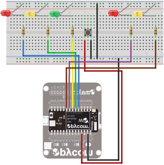
Figure 9-1. Wiring the Stoplight Simulation (WiPy)
Now, let’s look at the wiring diagram for the Pyboard. It is made a bit more complex due to the need for adding a networking breakout board.
Pyboard
Wiring for the Pyboard is best done orienting the board with the USB connector to the left. This will allow you to read the pin numbers on the board even after the wires are plugged into the board. There are additional connections needed here for the network module. Recall that the CC3000 breakout board requires additional wiring to connect the SPI interface to the Pyboard. Like we did for the LEDs, resistors, and button, we should plan for how to connect the breakout board. Table 9-3 shows the connections needed for the Pyboard when used with the CC3000 breakout board. If you are using a different breakout board, be sure to annotate this plan with your connections.
Table 9-3. Additional Connections for the Pyboard and CC3000 Breakout Board
Pyboard | CC3000 | Wire Color |
|---|---|---|
Y3 | IRQ | |
Y4 | VBEN | |
Y5 | CS | |
Y6 | CLK | |
Y7 | MISO | |
Y8 | MOSI | |
V+ | VIN | |
GND | GND |
With these additional wires needed, the Pyboard wiring diagram is a bit more complicated. Figure 9-2 shows the wiring diagram for the Pyboard with the CC3000 breakout board.
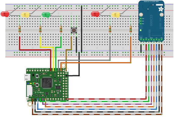
Figure 9-2. Wiring the Stoplight Simulation (WiPy)
Wow, that is a lot of wires! You can see the advantage of using a MicroPython board that has built-in WiFi – you don’t have to dedicate additional wires that can sometimes make a simple project more complex or when you look at your project all wired up – it looks like a nest of wiring.
Note
If you are using the Pyboard, you may be able to use the onboard LEDs instead of separate LEDs.
Finally, always make sure you wire your project carefully, double-checking all the connections – especially power, ground, and any pins used for signaling (will be set to “high” or “on”) such as those pins used for SPI interfaces. Most importantly, never plug or unplug jumper wires when the project (or your board) is powered on. This will very likely damage your board or components.
Caution
Never plug or unplug jumper wires when the project is powered on. You risk damaging your board or the components.
Once again, always make sure to double-check your connections before powering the board on. Now, let’s talk about the code we need to write. Don’t power on your board just yet – there is a fair amount of discussion needed before we’re ready to test the project.
Write the Code
Now it’s time to write the code for our project. The code isn’t overly complicated but it is a bit longer than the examples thus far. So, we are going to write the code in two parts. In the first part, we will see how to write code to simulate the pedestrian crosswalk button and traffic light. In the second part, we will forgo the use of a hardware button and instead use a web browser to control the button action remotely.
Note
These sections demonstrate the code for the WiPy and describe the differences for the Pyboard. See the complete code listing at the end of the chapter for the code for each board.
As you will see, part 2 will reuse most of the code from the first part but will be a bit more complicated with the HTML server code. Let’s begin with a look at part 1 of the project.
Part 1: Stoplight Simulator – Using a Pushbutton
The code for part 1 of the project will need to monitor the button and when pressed, cycle the lights as described above. We also need code to initialize the LEDs setting them to off initially. We can write functions for monitoring the button and cycling the LEDs. We will use an interrupt to tie the function for the button to the hardware so that we can avoid using a polling loop.
Imports
The imports for the project will require the Pin class from the machine library and the utime library. The following shows the imports for the WiPy.
from machine import Pinimport utime
The imports for the Pyboard also require the Pin class from the pyb library as well as the delay function and ExtInt class. The ExtInt class is used to set up an interrupt for the button to fire when the button is pressed.
from pyb import Pin, delay, ExtIntSetup
The setup code for this project will need to initialize the button and LED instances and then turn off all the LEDs (as a precaution) and turn on the green stoplight LED and the red walk signal LED. Listing 9-1 shows the code for setup and initialization.
Listing 9-1. Setup and Initialization of the Button and LEDs (WiPy)
# Setup the button and LEDsbutton = Pin('P23', Pin.IN, Pin.PULL_UP)led1 = Pin('P3', Pin.OUT)led2 = Pin('P4', Pin.OUT)led3 = Pin('P5', Pin.OUT)led4 = Pin('P6', Pin.OUT)led5 = Pin('P7', Pin.OUT)# Setup lists for the LEDsstoplight = [led1, led2, led3]walklight = [led4, led5]# Turn off the LEDsfor led in stoplight:led.value(0)for led in walklight:led.value(0)# Start with green stoplight and red walklightstoplight[2].value(1)walklight[0].value(1)
One thing to notice is how the button is initialized. This is a Pin object instance that is set up as an input (read) and the pull-up resistors are turned on. This allows the board to detect when the button is pressed because the value of the pin will be a positive value when the connection is made (the button is pressed).
Notice also I create a list that contains the LEDs for the stoplight and walk signal (named walklight in the code). This is mostly for demonstration so you can see how to manage lists of class objects. As you can see, it makes it easier to call the same function for all the objects in the list using a loop. Take note of this technique as you will need it from time to time in other projects.
The code for the Pyboard is largely the same. The differences include different pin numbers for the LEDs and buttons (see wiring diagram), different options for the initialization of the pins (Pin.OUT_PP instead of Pin.OUT), and the use of different functions for the Pin class: high() for value(1) and low() for value(0).
Functions
There are two functions needed for this part of the project. First, we need a function to cycle through the lights. Second, we need a function to monitor the button press. Let’s look at the cycle light function.
We will name the cycle lights function cycle_lights(). Recall we need to control how the lights change state. We do this with a specific cycle as described earlier. To recap, we call this function when we want to simulate changing the stoplight when the walk request button is pressed. Thus, this function will be called from the code for the button. Listing 9-2 shows the code for the cycle_lights() button. As you will see, the code is rather straightforward. The only tricky part may be the loop used to flash the yellow walk LED. Be sure to read through it so that you understand how it works.
Listing 9-2. The cycle_lights() Function (WiPy)
# We need a method to cycle the stoplight and walklight## We toggle from green to yellow for 2 seconds# then red for 20 seconds.def cycle_lights():# Go yellow.stoplight[2].value(0)stoplight[1].value(1)# Wait 2 secondsutime.sleep(2)# Go red and turn on walk lightstoplight[1].value(0)stoplight[0].value(1)utime.sleep_ms(500) # Give the pedestrian a chance to see itwalklight[0].value(0)walklight[1].value(1)# After 10 seconds, start blinking the walk lightutime.sleep(1)for i in range(0,10):walklight[1].value(0)utime.sleep_ms(500)walklight[1].value(1)utime.sleep_ms(500)# Stop=green, walk=redwalklight[1].value(0)walklight[0].value(1)utime.sleep_ms(500) # Give the pedestrian a chance to see itstoplight[0].value(0)stoplight[2].value(1)
The code for the Pyboard is very similar with the changes as noted previously for controlling the LEDs and use of the delay() function instead of the utime class sleep functions.
We will name the button function button_pressed(). This function is used as a callback for the button press interrupt. Technically, we tell MicroPython to associate this method with the pin interrupt but we will see that in a moment. However, there is another element to this function that requires explanation.
When we use a component like a button and the user (you) press the button, the contacts in the button do not go from an off state to and on state instantaneously. There is a very small period where the value read is erratic. Thus, we cannot simply say, “when the pin goes high” because the value read on the pin may “bounce” from low to high (or high to low) rapidly. This is called bouncing. We can overcome this artificially with code (as well as other techniques) – called debouncing.
In this case, we can check the value of the pin (button) over time and only “trigger” the button press if and only if the value remains stable during that time. Code for debouncing the pin is shown in Listing 9-3. Notice in the loop we wait for a value of 50. This is 50 milliseconds. If the trigger is long enough, we call the cycle_lights() function.
Listing 9-3. The button_pressed() Function (WiPy)
def button_pressed(line):cur_value = button.value()active = 0while (active < 50):if button.value() != cur_value:active += 1else:active = 0utime.sleep_ms(1)print("")if active:cycle_lights()else:print("False press")
Tip
For more information about debouncing and the techniques available to avoid it, see http://www.eng.utah.edu/∼cs5780/debouncing.pdf .
Finally, we need to set up the button to call the button_pressed() function when the board detects the interrupt. The following sets the callback function on the WiPy.
# Create an interrupt for the buttonbutton.callback(Pin.IRQ_FALLING, button_pressed)
The code on the Pyboard is also a single line of code but in this case, we must use the ExtInt class to set up the interrupt handler as shown below.
# Create an interrupt for the buttone = ExtInt('X1', ExtInt.IRQ_FALLING, Pin.PULL_UP, button_pressed)
Tip
See the online MicroPython documentation for more information about using the Pin callback for the WiPy and the interrupt for the Pyboard.
Now we’re all set to test the code. Go ahead and open a new file named ped_part1_wipy.py (or ped_part1_pyb.py for the Pyboard) and enter the code above. Listing 9-4 shows the complete code for part 1 of the project. If you’re using the Pyboard, it’s OK to cheat by looking at the complete listing at the end of the chapter.
Listing 9-4. Stoplight Simulation – Part 1 (WiPy)
# MicroPython for the IOT - Chapter 9## Project 2: A MicroPython Pedestrian Crosswalk Simulator# Part 1 - controlling LEDs and button as input## Required Components:# - WiPy# - (2) Red LEDs# - (2) Yellow LEDs# - (1) Green LED# - (5) 220 Ohm resistors# - (1) breadboard friendly momentary button## Note: this only runs on the WiPy.## Imports for the projectfrom machine import Pinimport utime# Setup the button and LEDsbutton = Pin('P23', Pin.IN, Pin.PULL_UP)led1 = Pin('P3', Pin.OUT)led2 = Pin('P4', Pin.OUT)led3 = Pin('P5', Pin.OUT)led4 = Pin('P6', Pin.OUT)led5 = Pin('P7', Pin.OUT)# Setup lists for the LEDsstoplight = [led1, led2, led3]walklight = [led4, led5]# Turn off the LEDsfor led in stoplight:led.value(0)for led in walklight:led.value(0)# Start with green stoplight and red walklightstoplight[2].value(1)walklight[0].value(1)# We need a method to cycle the stoplight and walklight## We toggle from green to yellow for 2 seconds# then red for 20 seconds.def cycle_lights():# Go yellow.stoplight[2].value(0)stoplight[1].value(1)# Wait 2 secondsutime.sleep(2)# Go red and turn on walk lightstoplight[1].value(0)stoplight[0].value(1)utime.sleep_ms(500) # Give the pedestrian a chance to see itwalklight[0].value(0)walklight[1].value(1)# After 10 seconds, start blinking the walk lightutime.sleep(1)for i in range(0,10):walklight[1].value(0)utime.sleep_ms(500)walklight[1].value(1)utime.sleep_ms(500)# Stop=green, walk=redwalklight[1].value(0)walklight[0].value(1)utime.sleep_ms(500) # Give the pedestrian a chance to see itstoplight[0].value(0)stoplight[2].value(1)# Create callback for the buttondef button_pressed(line):cur_value = button.value()active = 0while (active < 50):if button.value() != cur_value:active += 1else:active = 0utime.sleep_ms(1)print("")if active:cycle_lights()else:print("False press")# Create an interrupt for the buttonbutton.callback(Pin.IRQ_FALLING, button_pressed)
Test and Debug the Code
Testing this part of the project requires copying the source code file to the board and then executing it. Since the code was written without a run() function, simply importing it is all you need to do to run the code. Be sure to check all connections before powering on the board. Recall, the command we use to import and run the code once we connect to the board is shown below.
>>> import ped_part1_wipyOnce imported, the code will run and you can press the button to see the lights cycle through the stages. If you do not see any of the lights on (the green stoplight and red walk signal should be on), check the setup and initialization code. If the lights do not cycle when the button is pressed, check the code for the button to ensure you have it correct. If they do not illuminate in order, you may have the pins wired incorrectly. Be sure to check all wiring connections when encountering problems, always powering off the board before disconnecting or reconnecting any wires or components.
When the project is working, try it out a few times to ensure it works as expected. Then you should congratulate yourself! You’ve just wired together several discrete electronic components and made a working simulation of a pedestrian walk button and stoplight. Cool!
Now, let’s kick this project up a notch and make it accessible over the Internet. After all, that is what IOT is all about!
Part 2: Stoplight Simulator – Remote Control with HTML
The code for this part will use all the code from the first part but we will not need the code for the button. Instead, we will use the Socket class to create a listener to listen for a connection from a web browser. The code will send a short HTML-based response (a simple web page) to the client that includes a form containing two buttons – one for the walk request and another for shutting down the server code. The listener will listen on port 80.
Note
If you’re using the WiPy, you don’t need to add any networking code, but I’ll show you how to do so in case you want to run the project on your own network or connect it to the Internet.
The concept of the HTML server is quite simple. The code listens for a connection on the socket port then receives the request (in this case in the form of HTML GET method) and sends an HTML response (the web page). The code then checks to see if the request contains the form data from one of the two buttons: a button to request the walk cycle and another to shut down the server. As you will see, shutting down the server forces us to write the code a bit tidier.
If you’ve never used HTML code before, don’t worry as the example code will provide everything you need. You don’t have to learn HTML to use the project in this chapter (or the next), but a basic knowledge would be helpful if you want to elaborate on the project or use the HTML server concept for your own projects. A good source of information about HTML can be found at https://www.w3schools.com/html/ .
Let’s look at the changes needed for the imports section.
Imports
We need a few more libraries in the import section. We need the socket library (renamed with an alias for clarity), the machine library, and the WLAN class from the network library. It is perfectly normal to write the imports this way, but with a little imagination you can simplify them. Do you see how? The following shows the complete import section for the WiPy.
from machine import Pinimport usocket as socketimport utimeimport machinefrom network import WLAN
The imports for the Pyboard are a bit shorter. We need to add the SPI library for the network board and the network library as well as the socket library. The following shows the complete import section for the Pyboard.
from pyb import Pin, delay, ExtInt, SPIimport networkimport usocket as socket
Now, let’s look at the changes in the setup section.
Setup
For this part of the project, we need to add the code to connect our board to our network (or the Internet) via a wireless connection. We also need to place the HTML code here in the form of a string. This is typically where (and how) one defines a large string for use in Python. Using triple quotes on either side makes the string a documentation string (also called a docstring). See https://www.python.org/dev/peps/pep-0257/ for more details.
The networking code for the WiPy is the same code we saw earlier in the book. In this case, it sets up the wireless networking feature to connect to an existing wireless network rather than the default access point behavior of the WiPy. Listing 9-5 shows the network code for the WiPy.
Listing 9-5. Wireless Network Setup (WiPy)
# Setup the board to connect to our network.wlan = WLAN(mode=WLAN.STA)nets = wlan.scan()for net in nets:if net.ssid == 'YOUR_SSID':print('Network found!')wlan.connect(net.ssid, auth=(net.sec, 'YOUR_PASSWORD'), timeout=5000)while not wlan.isconnected():machine.idle() # save power while waitingprint('WLAN connection succeeded!')print("My IP address is: {0}".format(wlan.ifconfig()[0]))break
The networking code for the Pyboard is the same code we saw earlier in the book. In this case, it first sets up the SPI interface to a networking board (in this example a CC3000 breakout board), then initiates a wireless connection to an existing wireless network rather than the default access point behavior of the WiPy. Listing 9-6 shows the network code for the Pyboard.
Listing 9-6. Wireless Network Setup (Pyboard)
# Setup network connectionnic = network.CC3K(SPI(2), Pin.board.Y5, Pin.board.Y4, Pin.board.Y3)# Replace the following with yout SSID and passwordnic.connect("YOUR_SSID", "YOUR_PASSWORD")print("Connecting...")while not nic.isconnected():delay(50)print("Connected!")print("My IP address is: {0}".format(nic.ifconfig()[0]))
Tip
You must change the SSID and password in the code to match your network.
Another part of the setup is the HTML response code. This may seem like a difficult part of the code, but it is simple. We are constructing a string that we will send back to the client through the socket. This string contains HTML code starting with a header. Then, we supply a title (which appears in the title bar of your browser), some text to display on the page, and a form that contains the two buttons. These buttons are in a form that, when each is pressed, will send a HTML GET request through the socket to the server. Simple! Listing 9-7 shows the HTML string for the project. Again, don’t worry about the details. You can work on improving the web page later.
Listing 9-7. HTML Response String
# HTML web page for the projectHTML_RESPONSE = """<!DOCTYPE html><html><head><title>MicroPython for the IOT - Project 2</title></head><center><h2>MicroPython for the IOT - Project 2</h2></center><br><center>A simple project to demonstrate how to control hardware over the Internet.</center><br><br><form><center><button name="WALK" value="PLEASE" type="submit" style="height: 50px; width: 100px">REQUEST WALK</button><br><br><button name="shutdown" value="now" type="submit" style="height: 50px; width: 100px">Stop Server</button></center></form></html>"""
Notice the buttons in the code (<button></button> tags). The name and value will be sent in the request to the server. The type of the button is defined as submit and when placed on a form, causes the client to post the form data to the server when the button is pressed. Finally, the string before the end tag is the label that will be displayed on the button.
If you’re concerned about this being a huge string that takes up memory, you’re right it is and it does. If you are planning a project that uses a large HTML response or perhaps several responses, you may want to consider storing those in a file (one response per file) and reading the data from a file before sending it to the client. This will save some data space and could make the difference for larger projects that use more memory.
Don’t be concerned about the number of lines used here. The whitespace is used for decoration (mostly) so if you wanted to reduce its overall visual size, you can remove the whitespace but it is common practice to indent the HTML code like this for easier reading.
Tip
If you are concerned about security (who isn’t?), you can use secure socket layer connections to make your connection to your MicroPython board more secure. MicroPython provides a class named ussl that you can use. See the ussl class documentation for more information or you can look at the example at https://github.com/micropython/micropython/blob/master/examples/network/http_server_ssl.py .
There is one other important thing about using HTML on your MicroPython board that should be made clear: this example and many others you may find on the Internet should not be confused with a robust web server. More specifically, this example merely sends HTML back to the client once it detects a HTML GET method (request) from the client while listening on a network socket. So, this example is merely a simple HTML server and not a web server in the sense that it can do all manner of things a web server can do – it doesn’t. Thus, you should take care to code your projects to restrict operation to specific GET (or POST) requests and return the appropriate HTML response.
Now let’s look at how to make the run() function.
Functions
All that remains to do in the code is to change the code for the hardware button and make a run() function to contain the main portion of the code. In this project, that includes the code for setting up the socket and the listen and respond code. You can leave the button_pressed() function, but it is not needed. Listing 9-8 shows the code for the run() function.
Listing 9-8. The run() Function (WiPy)
# Setup the socket and respond to HTML requestsdef run():sock = socket.socket(socket.AF_INET, socket.SOCK_STREAM)sock.bind(('', 80))sock.listen(5)server_on = Truewhile server_on:client, address = sock.accept()print("Got a connection from a client at: %s" % str(address))request = client.recv(1024)# Process the request from the client. Payload should appear in pos 6.# Check for walk button clickwalk_clicked = (request[:17] == b'GET /?WALK=PLEASE')# Check for stop server button clickstop_clicked = (request[:18] == b'GET /?shutdown=now')if walk_clicked:print('Requesting walk now!')cycle_lights()elif stop_clicked:server_on = Falseprint("Goodbye!")client.send(HTML_RESPONSE)client.close()
Notice we begin the function with setting up the socket and binding it to port 80. The bind() function uses an empty string to instruct the socket to use the current IP address. Next, we tell the socket to listen on the socket with a five-second timeout using the listen(5) function. Then, we set a Boolean variable to loop over the listen and respond code while it is true. In this case, we use the Boolean and set it to False when the shutdown button is pressed.
Inside the loop is where things get interesting. The first thing we do is accept a connection from the socket using sock.accept(), which returns two items: the client object instance and the address of the client. We can print the address of the client for debugging purpose.
Next, we tell the client to receive up to 1024 bytes with the client.recv(1024) call. This will wait until there is a response from the client, so be aware this is not a preemptive loop – it will wait until the client responds. When the client does send data (like first connect or when a button is pressed), we can then search the string sent for the command.
Notice in the code we check for either the walk request searching for b'GET /?WALK=PLEASE' or the shutdown event searching for b'GET /?shutdown=now'. There is a bit of trickery going on here that warrants explanation. We use the request string as an array starting our search from the start for the number of characters in the string (17 or 18), which is represented with [:17] or [:18].
If the walk request is detected, we call the cycle_lights() function, which is unmodified from part 1. If the shutdown event is detected, we set the loop to terminate and then exit the run() function.
Take some time to read through the code until you understand how it works. When ready, go ahead and open a new file named ped_part2_wipy.py (or ped_part2_pyb.py for the Pyboard) and enter the code above.
Finally, you must remove the line of code that sets up the button callback (or on the Pyboard the ExtInt() call). It won’t hurt the code to leave it in, but since we’re not using the button, it is not needed and all unnecessary code should be removed.
Now, let’s look at the complete code for both the WiPy and Pyboard.
Completed Code
In this section, we will see the final, completed code for the WiPy and Pyboard. These listings are provided as a reference for you to ensure you have the correct code for your board. Listing 9-9 shows the complete code for running the project on the WiPy.
Listing 9-9. Complete Code for the Stoplight Simulation (WiPy)
# MicroPython for the IOT - Chapter 9## Project 2: A MicroPython Pedestrian Crosswalk Simulator# Part 3 - controlling LEDs over the Internet## Required Components:# - WiPy# - (2) Red LEDs# - (2) Yellow LEDs# - (1) Green LED# - (5) 220 Ohm resistors## Note: this only runs on the WiPy.## Imports for the projectfrom machine import Pinimport usocket as socketimport utimeimport machinefrom network import WLAN# Setup the board to connect to our network.wlan = WLAN(mode=WLAN.STA)nets = wlan.scan()for net in nets:if net.ssid == 'YOUR_SSID':print('Network found!')wlan.connect(net.ssid, auth=(net.sec, 'YOUR_PASSWORD'), timeout=5000)while not wlan.isconnected():machine.idle() # save power while waitingprint('WLAN connection succeeded!')print("My IP address is: {0}".format(wlan.ifconfig()[0]))break# HTML web page for the projectHTML_RESPONSE = """<!DOCTYPE html><html><head><title>MicroPython for the IOT - Project 2</title></head><center><h2>MicroPython for the IOT - Project 2</h2></center><br><center>A simple project to demonstrate how to control hardware over the Internet.</center><br><br><form><center><button name="WALK" value="PLEASE" type="submit" style="height: 50px; width: 100px">REQUEST WALK</button><br><br><button name="shutdown" value="now" type="submit" style="height: 50px; width: 100px">Stop Server</button></center></form></html>"""# Setup the LEDs (button no longer needed)led1 = Pin('P3', Pin.OUT)led2 = Pin('P4', Pin.OUT)led3 = Pin('P5', Pin.OUT)led4 = Pin('P6', Pin.OUT)led5 = Pin('P7', Pin.OUT)# Setup lists for the LEDsstoplight = [led1, led2, led3]walklight = [led4, led5]# Turn off the LEDsfor led in stoplight:led.value(0)for led in walklight:led.value(0)# Start with green stoplight and red walklightstoplight[2].value(1)walklight[0].value(1)# We need a method to cycle the stoplight and walklight## We toggle from green to yellow for 2 seconds# then red for 20 seconds.def cycle_lights():# Go yellow.stoplight[2].value(0)stoplight[1].value(1)# Wait 2 secondsutime.sleep(2)# Go red and turn on walk lightstoplight[1].value(0)stoplight[0].value(1)utime.sleep_ms(500) # Give the pedestrian a chance to see itwalklight[0].value(0)walklight[1].value(1)# After 10 seconds, start blinking the walk lightutime.sleep(1)for i in range(0,10):walklight[1].value(0)utime.sleep_ms(500)walklight[1].value(1)utime.sleep_ms(500)# Stop=green, walk=redwalklight[1].value(0)walklight[0].value(1)utime.sleep_ms(500) # Give the pedestrian a chance to see itstoplight[0].value(0)stoplight[2].value(1)# Setup the socket and respond to HTML requestsdef run():sock = socket.socket(socket.AF_INET, socket.SOCK_STREAM)sock.bind(('', 80))sock.listen(5)server_on = Truewhile server_on:client, address = sock.accept()print("Got a connection from a client at: %s" % str(address))request = client.recv(1024)# Process the request from the client. Payload should appear in pos 6.# Check for walk button clickwalk_clicked = (request[:17] == b'GET /?WALK=PLEASE')# Check for stop server button clickstop_clicked = (request[:18] == b'GET /?shutdown=now')if walk_clicked:print('Requesting walk now!')cycle_lights()elif stop_clicked:server_on = Falseprint("Goodbye!")client.send(HTML_RESPONSE)client.close()sock.close()
Now, let’s see the code for the Pyboard. As you will see, it is largely the same except for the networking code, imports, and pin function calls. Listing 9-10 shows the complete code for running the project on the Pyboard.
Listing 9-10. Complete Code for the Stoplight Simulation (Pyboard)
# MicroPython for the IOT - Chapter 9## Project 2: A MicroPython Pedestrian Crosswalk Simulator# Part 2 - Controlling the walklight remotely## Required Components:# - Pyboard# - (2) Red LEDs# - (2) Yellow LEDs# - (1) Green LED# - (5) 220 Ohm resistors# - (1) breadboard friendly momentary button# - (1) CC3000 breakout board## Note: this only runs on the Pyboard.## Imports for the projectfrom pyb import Pin, delay, ExtInt, SPIimport networkimport usocket as socket# Setup network connectionnic = network.CC3K(SPI(2), Pin.board.Y5, Pin.board.Y4, Pin.board.Y3)# Replace the following with yout SSID and passwordnic.connect("YOUR_SSID", "YOUR_PASSWORD")print("Connecting...")while not nic.isconnected():delay(50)print("Connected!")print("My IP address is: {0}".format(nic.ifconfig()[0]))# HTML web page for the projectHTML_RESPONSE = """<!DOCTYPE html><html><head><title>MicroPython for the IOT - Project 2</title></head><center><h2>MicroPython for the IOT - Project 2</h2></center><br><center>A simple project to demonstrate how to control hardware over the Internet.</center><br><br><form><center><button name="WALK" value="PLEASE" type="submit" style="height: 50px; width: 100px">REQUEST WALK</button><br><br><button name="shutdown" value="now" type="submit" style="height: 50px; width: 100px">Stop Server</button></center></form></html>"""# Setup the LEDsled1 = Pin('X7', Pin.OUT_PP)led2 = Pin('X6', Pin.OUT_PP)led3 = Pin('X5', Pin.OUT_PP)led4 = Pin('X4', Pin.OUT_PP)led5 = Pin('X3', Pin.OUT_PP)# Setup lists for the LEDsstoplight = [led1, led2, led3]walklight = [led4, led5]# Turn off the LEDsfor led in stoplight:led.low()for led in walklight:led.low()# Start with green stoplight and red walklightstoplight[2].high()walklight[0].high()# We need a method to cycle the stoplight and walklight## We toggle from green to yellow for 2 seconds# then red for 20 seconds.def cycle_lights():# Go yellow.stoplight[2].low()stoplight[1].high()# Wait 2 secondsdelay(2000)# Go red and turn on walk lightstoplight[1].low()stoplight[0].high()delay(500) # Give the pedestrian a chance to see itwalklight[0].low()walklight[1].high()# After 10 seconds, start blinking the walk lightdelay(10000)for i in range(0,10):walklight[1].low()delay(500)walklight[1].high()delay(500)# Stop=green, walk=redwalklight[1].low()walklight[0].high()delay(500) # Give the pedestrian a chance to see itstoplight[0].low()stoplight[2].high()# Setup the socket and respond to HTML requestsdef run():sock = socket.socket(socket.AF_INET, socket.SOCK_STREAM)sock.bind(('', 80))sock.listen(5)server_on = Truewhile server_on:client, address = sock.accept()print("Got a connection from a client at: %s" % str(address))request = client.recv(1024)# Process the request from the client. Payload should appear in pos 6.# Check for walk button clickwalk_clicked = (request[:17] == b'GET /?WALK=PLEASE')# Check for stop server button clickstop_clicked = (request[:18] == b'GET /?shutdown=now')if walk_clicked:print('Requesting walk now!')cycle_lights()elif stop_clicked:server_on = Falseprint("Goodbye!")client.send(HTML_RESPONSE)client.close()sock.close()
Ok, now we’re ready to execute the project.
Execute!
Now is the fun part! We’ve got the code all set up to control our LEDs and we know it works from part 1. We also have code to set up a socket listener to accept connections over port 80 on our MicroPython board. All we need now is the IP address of that board to point our web browser. We can get that from our debug statements by running the code. Listing 9-11 shows the initial run for the project on a WiPy (results for the Pyboard are similar).
Listing 9-11. Running the Stoplight Simulation (WiPy)
MicroPython v1.8.6-694-g25826866 on 2017-06-29; WiPy with ESP32Type "help()" for more information.>>> import ped_part3_wipy as wNetwork found!WLAN connection succeeded!My IP address is: 192.168.42.128>>> w.run()Got a connection from a client at: ('192.168.42.127', 49236)Got a connection from a client at: ('192.168.42.127', 49237)Got a connection from a client at: ('192.168.42.127', 49243)Requesting walk now!Got a connection from a client at: ('192.168.42.127', 49254)Goodbye!>>>
Notice in this case the IP address is 192.168.42.127. All we need to do is put that in our browser and shown in Figure 9-3.
Caution
If you’re using the WiPy and telnet to open a REPL console, be advised that as soon as you run the networking portion of the code, your REPL console will disconnect. This is because the IP address will change! So, when working with the WiPy connecting it to your network, it is best to use the screen or another terminal program over USB to get a REPL console.
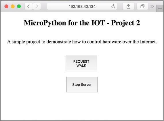
Figure 9-3. Stoplight Simulation Project
Once you enter the URL, you should see a web page like the image shown. If you don’t, be sure to check the HTML in your code to ensure it is exactly like what is shown; otherwise, the page may not display properly. You should also ensure the network your PC is connected to can reach the network to which your board is connected. If your home office is set up like mine, there may be several WiFi networks you can use. It is best if your board and your PC are on the same network (and same subnet).
Once you get that sorted out, go ahead and play with the buttons. Remember, the walk button will engage and you will see the lights cycle but you won’t be able to do anything until the walk cycle is complete. This is because we don’t return the response HTML until after the cycle is complete (see the code to convince yourself). Also, when you click the shutdown button, you will need to restart the code to rerun it. Simply call the run() function again.
Take another look at the listing above. Notice there are debug messages printed for each time the client connects (the code accepts the connection and GET request) as well as a statement about what it is doing. You should see something similar in your REPL console.
It is at this point that you should be basking in the wonder of your first successful MicroPython IOT remote control hardware project. Take some time to enjoy a job well done.
The final step in the process is optional for this project since you are unlikely to want it to run more than to just test it. However, if you do want to make it run every time you boot your board, you can modify the main.py code module on the board to import your code and call the run() function.
At this point, you’ve completed your first real MicroPython IOT project. We can call it an IOT project because it uses the Internet, but it is only a simulation and doesn’t actually control a real traffic light, but the techniques we saw in this project permit us to connect our MicroPython board to the Internet and interact with it - which is what the IOT is all about!
Taking it Further
This project shows excellent prospects for reusing the techniques in other projects. This is especially true for the HTML server aspect. If you liked controlling your MicroPython board over the Internet, you should consider taking time to explore some embellishments. Here are a few you may want to consider. Some are easy and some may be a challenge or require more research.2
Use NeoPixels ( https://www.adafruit.com/category/168 ) instead of LEDs. These are RGB LEDs so you need only two - one for the stoplight and one for the walk light. See https://github.com/JanBednarik/micropython-ws2812 for more information and examples.
Modify the HTML response to show the state of the lights.
Explore the HTML code to change the web page to your liking. Consider using cascading style sheets to change the background of the button when pressed.
Connect your board to the Internet and call a friend to connect to your board and try it out.
Use a display in place of the LEDs for the walk sign to show “WALK” or “DON’T WALK.”
Of course, if you want to press on to the next project, you’re welcome to do so but take some time to explore these potential embellishments – it will be good practice.
If you’re up for a real challenge, you can reuse the code for this project and replace the button logic with a relay board that allows you to use a low-voltage device like the MicroPython board to turn on or off a higher voltage circuit. In this case, you can use the HTML button to turn the relay on or off over the Internet.
Summary
Working with discrete electronic components can be a lot of fun. Just making the circuit work is a real thrill when you’re just starting out with electronics. Now that we know a lot more about MicroPython, we can see how powerful it is to have an easy-to-program language like Python at our disposal to work with directly with hardware – even over the Internet.
In this chapter, we implemented a simulation of a pedestrian crosswalk button and stoplight. We used a series of LEDs to represent the stoplight and walk signal. We also added a hardware button to simulate pressing the real walk button and then turned that into a remote-control button we hosted via simple HTML right from our MicroPython board. If you liked this project, you will enjoy the next two projects even more.
In the next chapter, we will explore a project that uses a sensor to read values and then archive the data and display it on a web page when requested. This is the next-to-last step in our journey of building a true MicroPython IOT project. This chapter and the next one show you how to make data available over the Internet and the final project chapter will show you how to make your sensor data available through cloud services.
Footnotes
1 A highly technical term that describes a state of extreme chaos and general failure to execute. Not to be confused with hinky, which indicates a slightly less severe case when something works but isn’t quite right.
2 I include these so you can grow your knowledge beyond the confines of this book. Try these when you’ve finished the other projects in the book.