
The MicroPython firmware, at the most basic of functionality, is the same from board to board for all the general Python language supported and many of the built-in functions. However, some of the libraries in the MicroPython firmware have a few minor differences from one board to another. In some cases, there are more libraries or classes available than others or perhaps the classes are organized differently, but most implement the same core libraries in one form or another. The same cannot be said to be true at the lower-level hardware abstraction layers . This is simply because one board vendor may implement different hardware than others. In some cases, the board has features that are not present on other boards. For example, the WiPy has WiFi and Bluetooth but the Pyboard has neither.
In this chapter, we will look at several examples of the low-level hardware support in MicroPython. We will learn about the board-specific libraries as well as some of the lower-level specialized libraries such as those for Bluetooth, SPI, I2C, and more. We will also see short code examples to illustrate the capabilities of the board-specific libraries. Some of these will be short snippets of code rather than actual projects you can implement yourself.
However, there are a few that are complete projects, which you may want to explore, but most are explained without a lot of depth and are intended to be examples rather than detailed walkthroughs. Also, keep in mind they will likely require a specific breakout board and MicroPython board as well as other accessories to implement. Again, these are for demonstration purposes. We will see more complete, step-by-step examples in later chapters, including how to assemble the hardware.
To keep things brief, we will explore the board-specific libraries that differ on the Pyboard and WiPy. Other boards may be different further still, but you will need to check the vendor documentation to know how they differ. This chapter should provide you with the insight to find those differences. We will also revisit working with breakout boards to demonstrate some of the libraries and hardware protocols and techniques discussed in previous chapters.
Let’s begin with a look at the board-specific libraries for the Pyboard and WiPy.
Board-Specific Libraries
We have already seen that there are differences in the machine library between the Pyboard and WiPy. But there are other differences: libraries that are specific to each board and thus can only be used with another of the same board. These include libraries with functions and classes to work with low-level hardware , board-specific functions, and constants, etc.
Perhaps the one thing you should remember when working with a new MicroPython board for the first time is the firmware at the hardware level is very likely to be different from the last MicroPython board you used. This is especially true when you look at the firmware ports for boards like the BBC micro:bit, Circuit Playground, ESP8266, etc.
Tip
Be sure to visit the documentation for your board for a complete list of functions, uses, and more examples of the board-specific libraries.
Pyboard
The Pyboard-specific libraries are unique in that they contain support for their vendor-specific skins. As we learned in Chapter 3, there are several skins available for the Pyboard. Fortunately, all the skins are supported directly in the firmware with Pyboard-specific classes. This includes the audio skin, LCD, and more.
There are also libraries specific to the Pyboard itself in the form of the pyb library, which includes support for several board-specific functions including time, power, interrupt, and more. We will also take a brief tour of that library and then look at one of the libraries for the LCD skin: the lcd160cr class.
The following sections briefly describe the libraries in more detail and include a few commonly found examples of some of the features. See the indicated documentation for complete details of the contents and features of each library.
pyb
The pyb library is the catch-all library for the Pyboard-related functions and classes. If you’re looking for a function or library related to the Pyboard or any of its on-board hardware, this library is the place you should look first. The following lists the function groups and classes available.
Time: time-related functions for delays by millisecond or microsecond and calculating the number of milliseconds or microseconds since an event (saved variable)
Reset: functions that permit you to turn on debug, initiate bootloader mode, or reset the board
Interrupt: enable or disable interrupts
Power: functions to put the board into sleep or deep sleep mode and change the performance characteristics (tread lightly)
Miscellaneous: various functions for information, controlling UART, USB, and mounting block devices
Now let’s see a few short examples. The first two show examples of the reset functions, the second two are miscellaneous functions, and the last shows how to use one of the classes to interact with the hardware on the board.
You can use the pyb.hard_reset() function to perform a hard reset as follows. If you enter this statement in a REPL console, the board will reset in the same manner as if you pressed the reset button. This could be handy if you need to abort from a serious error or hardware fault.
MicroPython v1.9.1-154-g4d55d880 on 2017-07-11; PYBv1.1 with STM32F405RGType "help()" for more information.>>> import pyb>>> pyb.hard_reset()
Note
The hard_reset() function can cause your PC to complain that the SD card was ejected without stopping the file system, so use this function sparingly.
The pyb.bootloader() function places the board in bootloader mode. Recall from Chapter 3, to install firmware, hard to power off the board, install a jumper wire, and power the board on before we can load firmware. With this function, you can do so from the REPL console. That is, if you can get to a REPL console. If your board is damaged or the firmware is corrupt, you can still perform the jumper wire process to place the board in bootloader mode to load new firmware.
The pyb.info() function is used as an informational dump. It prints out lots of low-level information about the board including hardware addresses and more. Most of it is not useful unless you’re writing low-level drivers or something similar, but you can pass True to the function and get more information in the form of a dump of the GC memory layout as shown in the excerpt below. If you’re curious about this data, see the Pyboard hardware specification section in the online reference manual or the forums at forum.micropython.org.
>>> pyb.info(True)...LFS free: 52224 bytesGC memory layout; from 20003e40:00000: h=hhhhhBShh==Sh=hhhh==h==Bh=hBh=hBhThShh=h==hh=BhhhBhBh=hh=hBh=h00400: =hTh==Shhhh==B........h=....................................h===00800: ====h===========================================================00c00: ==============..................................................(92 lines all free)18000: ............................
The pyb.main(filename) function is one the most useful functions. It sets the filename of the main script to run after boot.py is finished. You can use this function in conjunction with several alternative main.py code modules. This can be a useful tool if you wanted to implement a few projects that launch and run automatically. Rather than going into the boot.py manually and changing it, you can use this function to tell the Pyboard to start with an alternative file. That way, you can have “profiles” you can use to change the behavior of the board. Cool. Simply call the function with a valid code module path and name (as a string). This setting remains in effect until you change it.
Note
You should only call this function from within boot.py.
The pyb library also has low-level hardware classes for a host of hardware supported. Note that we saw a similar set of classes for the WiPy in the machine library. On the Pyboard, they’re in the pyb library. Table 6-1 shows a list of the available hardware classes. As you can see, there is support for the LEDs, LCD (we’ll see this one in a later section), GPIO pins, and much more. Keep in mind the class names are case sensitive.
Table 6-1. Pyboard Low-Level Hardware Classes (pyb library)
Class | Description |
|---|---|
Accel | accelerometer control |
ADC | analog to digital conversion |
CAN | controller area network communication bus |
DAC | digital to analog conversion |
ExtInt | configure I/O pins to interrupt on external events |
I2C | a two-wire serial protocol |
LCD | LCD control for the LCD touch-sensor pyskin |
LED | LED object |
Pin | control I/O pins |
PinAF | Pin Alternate Functions |
RTC | real-time clock |
Servo | 3-wire hobby servo driver |
SPI | a master-driven serial protocol |
Switch | switch object |
Timer | control internal timers |
TimerChannel | set up a channel for a timer |
UART | duplex serial communication bus |
USB_HID | USB Human Interface Device (HID) |
USB_VCP | USB virtual comm port |
Now, let’s see one of these in action. We will use the accelerometer to do a simple test of the board. That is, we will write some code that you can use to run and detect when the Pyboard has been physically moved in any of the three directions. The following shows the methods available for the Accel class .
Accel.filtered_xyz(): get a 3-tuple of filtered x, y and z values
Accel.tilt(): get the tilt register
Accel.x(): get the x-axis value
Accel.y(): get the y-axis value
Accel.z(): get the z-axis value
An accelerometer is a device used to measure the change in velocity over time: in other words, how an object has moved and how fast. While the accelerometer on the Pyboard is not a precision instrument capable of super-fine detection of minute movement, you can use it to detect when the board has been moved and even to a limited degree which direction (axis of movement). Thus, you can incorporate the accelerometer in your project if you want to know when the project has been moved either for security or to detect or change behavior based on orientation. There are a lot of cool ways you can use an accelerometer!
Now, let’s see some code! The following shows how you can use the accelerometer to get its raw values for each of the X, Y, and Z axes. Values range from -32 to 32. With a little observation, we can deduce what values indicate how far the board is moved in each direction. Try the code below and gently pick up the board and move it around in three dimensions by rotating it different directions. Do it slowly, then a bit more quickly and notice how the values change. Then, place the board back in its original position and observe. You can press CTRL-C to stop the loop.
import pybfrom pyb import Accelacc = Accel()print("Press CTRL-C to stop.")while True:pyb.delay(500) # Short delay before samplingprint("X = {0:03} Y = {1:03} Z = {2:03}".format(acc.x(), acc.y(), acc.z()))
The following shows an excerpt of the output when run in the REPL console.
X = 002 Y = 000 Z = 021X = 000 Y = -01 Z = 023X = 005 Y = 020 Z = 000X = -05 Y = 016 Z = -11X = -11 Y = -13 Z = 014X = 022 Y = -04 Z = -05X = -03 Y = 019 Z = 012...
If you’d like a challenge, you can try writing a script to use the accelerometer to detect when the board has been turned upside down. Hint: observe the X, Y, and Z raw values as you experiment and write your code to look for specific ranges.
Caution
On the Pyboard, the accelerometer uses I2C(1) so you cannot use the accelerometer and I2C(1) at the same time. You must use different pins for I2C to use the accelerometer and an I2C device at the same time.
These examples are only a very small portion of what is available in this library. If you’re working with the Pyboard, you should look at this library first for all your low-level hardware and board-specific control needs. We will see examples of some of the classes available and their use in a later section.
Tip
See http://docs.micropython.org/en/latest/pyboard/library/pyb.html for a complete list of the functions and classes available in the pyb library.
lcd160cr
The makers of the Pyboard have made an interesting skin that is, so far, unique among the vendors offering MicroPython boards. This skin is called the lcd160cr; hence LCD, which is a touch-sensitive LCD screen that you can connect directly to your Pyboard giving you a very nice touch screen that you can use to make a modern user interface. Think about it – you can build a MicroPython wristwatch, weather sensor, or anything that needs a user interface.
The library that is built in to the Pyboard firmware (named lcd160cr), allows you to sense when the screen is touched (and where), and you can send text or draw shapes. This means, with a little imagination, you can build simple graphical user interfaces. Very nice.
The LCD can be mounted in one of two locations, which are referred to as positions X and Y. These values are then used in the constructor. Figure 6-1 shows the positions for connecting the LCD to the Pyboard in the X and Y positions (shown left to right).
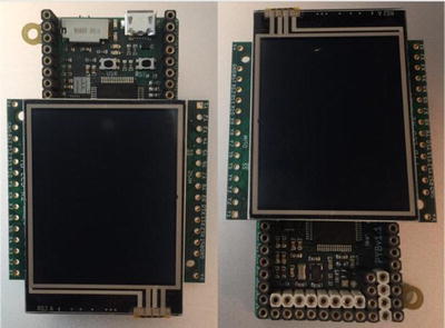
Figure 6-1. Positions for Mounting the LCD (Pyboard)
The difference in the position refers to with how the LCD is oriented on the Pyboard. In the X position, the LCD is mounted on X range of GPIO pins and in the Y position, it is mounted on the Y range of GPIO pins. Note that in the Y position, the LCD must be rotated 180 degrees as shown.
Now, let’s see an example of using the LCD. In this example, we will create a simple user interface that detects touch in the four corners of the screen. To make it interesting, we will also turn on a different LED with each touch. This will give you visual feedback that you’ve touched the screen.
This example is one of the longer examples in this book but it is not difficult to follow. Let’s begin with a high-level walkthrough of the code.
The first thing we should do is write the import statements so that we can detect when the code is run on a Pyboard (or another board). If it isn’t a Pyboard , we should abort since other boards do not have the library we will need (lcd160cr). If you adopt this technique in your own code, you can avoid strange import exceptions and other issues that may not be clear as to why the program fails. Plus, it’s good programming. The following shows the code for detecting the presence of the libraries needed and how to exit the program if one of them fails to import.
# First, make sure this is running on a Pyboardtry:import pybexcept ImportError:print("ERROR: not on a Pyboard!")sys.exit(-1)# Next, make sure the LCD skin library in the firmwaretry:import lcd160crexcept ImportError:print("ERROR: LCD160CR library missing!")sys.exit(-1)
Next, we will write a function to turn the LED on. This is an example of how to write code to be reusable. That is, we don’t want to repeat the same code repeatedly. In this case, we can turn on a specific LED by color. To help us with that, we can write a function to retrieve the LED based on color (1=red, 2=green, etc.). The following shows the helper function .
def led_color(num):if num == 1: return "red"elif num == 2: return "green"elif num == 3: return "orange"else: return "blue"
The following shows the reusable function for turning on the LED. As you can see, we first turn off the old LED then turn the new (selected) one on.
def turn_on_led(num, led_last):# turn last LED offled = pyb.LED(led_last)led.off()led = pyb.LED(num)led.on()sys.stdout.write("Turning off ")sys.stdout.write(led_color(led_last))sys.stdout.write(" - Turning on ")sys.stdout.write(led_color(num))sys.stdout.write(" ")
Next, we can write the code to read the position on the LCD that was touched and, depending on where the touch occurred, turn on the LED for that corner. We will use red for the upper-left, green for upper-right, orange for lower-right, and blue for lower-right.
The code is simplified by using numbers for the LEDs since the pyb.LED() refers to LEDs by numbers. Savvy readers may spot a way to improve the code with enumeration or even the use of constants. If you see these potential improvements, feel free to make those improvements as an exercise. Listing 6-1 shows the completed code for the example.
Listing 6-1. Using the Pyboard LCD (lcd160cr)
# MicroPython for the IOT - Chapter 6# Example module for the LCD skin on a Pyboard## Note: The LCD is positioned in the "X" position.#import sys# First, make sure this is running on a Pyboardtry:import pybexcept ImportError:print("ERROR: not on a Pyboard!")sys.exit(-1)# Next, make sure the LCD skin library in the firmwaretry:import lcd160crexcept ImportError:print("ERROR: LCD160CR library missing!")sys.exit(-1)# Return color of LEDdef led_color(num):if num == 1: return "red"elif num == 2: return "green"elif num == 3: return "orange"else: return "blue"# Use a method to turn off last LED and the next one ondef turn_on_led(num, led_last):# turn last LED offled = pyb.LED(led_last)led.off()led = pyb.LED(num)led.on()sys.stdout.write("Turning off ")sys.stdout.write(led_color(led_last))sys.stdout.write(" - Turning on ")sys.stdout.write(led_color(num))sys.stdout.write(" ")# Setup the LCD in the "X" positionlcd = lcd160cr.LCD160CR('X')for j in range(1, 4): # Turn off all of the LEDsled = pyb.LED(j) # Get the LEDled.off() # Turn the LED off# Now, let's play a game. Let's change the LEDs to# different colors depending on where the user touches# the screen.print("Welcome to the touch screen demo!")print("Touch the screen in the corners to change the LED lit.")print("Touch the center to exit.")center = Falselast_led = 1while not center:pyb.delay(50)if lcd.is_touched:touch = lcd.get_touch()if (touch[0] == 0):continue# Upper-left cornerif ((touch[1] <= 60) and (touch[2] <= 60)):turn_on_led(1, last_led)last_led = 1# Upper-right cornerelif ((touch[1] >= 100) and (touch[2] <= 60)):turn_on_led(2, last_led)last_led = 2# Lower-right cornerelif ((touch[1] >= 100) and (touch[2] >= 100)):turn_on_led(3, last_led)last_led = 3# Lower-left cornerelif ((touch[1] <= 60) and (touch[2] >= 100)):turn_on_led(4, last_led)last_led = 4# Centerelif ((touch[1] > 60) and (touch[1] < 100) and (touch[2] > 60) and (touch[2] < 100)):led = pyb.LED(last_led)led.off()center = Trueprint("Thanks for playing!")sys.exit(0)
If you have an LCD, go ahead and try this example. Once you do, you should see the LEDs light as you touch each corner and you will see in your REPL console output like the following.
>>> import pyboard_lcdWelcome to the touch screen demo!Touch the screen in the corners to change the LED lit.Touch the center to exit.Turning off red - Turning on greenTurning off green - Turning on redTurning off red - Turning on redTurning off red - Turning on orangeTurning off orange - Turning on greenTurning off green - Turning on greenTurning off green - Turning on orangeTurning off orange - Turning on blueTurning off blue - Turning on redThanks for playing!
Tip
The LCD comes with a thin protector on it. You will want to remove that and use a stylus or similar soft pointer to test the script. If your fingers are large, you may have some difficulty touching the small area designated.
If you decide to try out the example yourself, you should find it gives you a few moments of satisfaction of achieving an interesting doodad. If you like this example and want to get an LCD for your own projects, see the MicroPython store to order one ( https://store.micropython.org/store/#/products/LCD160CRv1_0H ). You will find you can purchase one with headers or without. You may choose one without if you decide to get the nifty (optional) aluminum case, which requires mounting a different, angled header (you must order and solder them yourself). However, you can use the LCD with headers as shown in this example.
Tip
See http://micropython.org/resources/LCD160CRv10-refmanual.pdf for the reference manual for the lcd160cr, which includes the low-level specification for working with the skin.
WiPy
The WiPy-specific libraries are unique in that they contain support for a complete range of Pycom boards including the Expansion Board, PySense, and PyTrack shields.
There are also libraries specific to the Pyboard itself in the form of the pycom library, which includes support for changing the heartbeat LED including changing the color. The AES library contains an interesting feature for securing data – AES encryption. We will explore this library in more detail. Also, recall that the WiPy firmware contains the low-level hardware for I2C, SPI, etc., in the machine library as opposed to the Pyboard, which has these in the pyb library.
The following sections briefly describe the libraries in more detail including a few commonly found examples of some of the features. See the indicated documentation for complete details of the contents and features of each library.
pycom
The pycom library has functions to control specific features of the Pycom devices, such as the heartbeat RGB LED. In fact, you can change the color of the LED, turn it on or off, and get the current state of the LED. While this seems very rudimentary, you can use the heartbeat LED to communicate status information. For example, you can change the color to indicate different actions (or states) such as reading from sensors, saving data, communicating errors, etc.
Let’s look at a short example of using the heartbeat LED to set state. Note that the LED color is defined by a 24-bit value representing red, green, and blue (RGB), where the red color is represented by the most significant 8 bits, green the next 8 bits, and blue the least significant 8 bits. We normally represent these values in hexadecimal.1 For example, bright white is 0xFFFFFF, 0xFFFF00 is yellow, and 0x00FFFF is a sea green.
In this example, we will use a set of helper functions and a test loop to work with the heartbeat LED. Note that to turn on (use) the heartbeat LED, you must first turn off the heartbeat internal feature with heartbeat(False). Listing 6-2 shows the example code for working with the heartbeat LED to show status/state.
Listing 6-2. Using the Heartbeat LED for Status/State (WiPy)
# MicroPython for the IOT - Chapter 6# Example for working with the hearbeat LED as a# status/state indicator#import utime# First, make sure this is running on a Pyboardtry:import pycomexcept ImportError:print("ERROR: not on a WiPy (or Pycom) board!")sys.exit(-1)# State/status enumeration_STATES = {'ERROR' : 0xFF0000, # Bright red'READING' : 0x00FF00, # Green'WRITING' : 0x0000FF, # Blue'OK' : 0xFF33FF, # Pinkish}# Clear the state (return to normal operation)def clear_status():pycom.heartbeat(True)# Show state/status with the heatbeat LEDdef show_status(state):pycom.heartbeat(False)pycom.rgbled(state)# Now, demonstrate the state changesfor state in _STATES.keys():show_status(_STATES[state])utime.sleep(3)# Return heartbeat to normalclear_status()
If you run this code, you will notice the LED will present some very bright colors. So, don’t stare directly at the LED! You can try reducing the brightness as an exercise using some more subtle color values.
Tip
See the online calculator at http://www.rapidtables.com/web/color/RGB_Color.htm to determine the desired color.
AES
WiPy has a special library named crypto, which has the AES library with support for AES (Advanced Encryption Standard) - a symmetric block cipher standardized by NIST. While you may not need this feature, for those of us concerned about protecting sensitive data, this could be a nifty feature worthy of consideration.
For example, you may want to transmit data over the Internet to another system. If you do not protect the data with encryption, it is not too difficult to decipher the data should it be exploited in some manner. If you encrypt the data (and protect the keys!), you can make it much more difficult for people to see the data.
Note
Encryption is an advanced feature that most beginners will not use. Thus, this section is brief. If you want to learn more about this library, see https://docs.pycom.io/chapter/firmwareapi/pycom/aes.html .
The AES library offers several constants to control the encryption mode and two functions: one to encrypt and another to decrypt. You will need to provide a key to use in the encryption algorithm for the simplest form of encryption defined by the constant, AES.MODE_ECB, which means Electronic Code Book. Other forms may need additional parameters.
There is one caveat. The data you encrypt must be in multiples of 16 byte blocks. Notice how we use spaces to make the strings 16 bytes. So, if you’re encrypting data that you’ve created or read from a sensor or another node on your network, will need to ensure you encrypt with blocks in multiple of 16 bytes.
Let’s look at an example. In this example, we will create a file with encrypted data to show how to protect your data for saving or sending to another node (computer). We will then open the file and read the data decrypting it so that we can show how to decipher encrypted data. We will use strings to make it easier but you can encrypt binary data too. Listing 6-3 shows the example code to use AES encryption to protect data.
Listing 6-3. Using Encryption to Protect Data (WiPy)
# MicroPython for the IOT - Chapter 6# Simple example for working with encrypting data#import sys# First, make sure this is running on a WiPy (pycom)try:import pycomfrom crypto import AESexcept ImportError:print("ERROR: not on a WiPy (or Pycom) board!")sys.exit(-1)# Setup encryption using simple, basic encryption# NOTICE: you normally would protect this key!my_key = b'monkeybreadyummy' # 128 bit (16 bytes) keycipher = AES(my_key, AES.MODE_ECB)# Create the file and encrypt the datanew_file = open("secret_log.txt", "w") # use "write" modenew_file.write(cipher.encrypt("1,apples,2.5 ")) # write some datanew_file.write(cipher.encrypt("2,oranges,1 ")) # write some datanew_file.write(cipher.encrypt("3,peaches,3 ")) # write some datanew_file.write(cipher.encrypt("4,grapes,21 ")) # write some datanew_file.close() # close the file# Step 2: Open the file and read dataold_file = open("secret_log.txt", "r") # use "read" mode# Use a loop to read all rows in the filefor row in old_file.readlines():data = cipher.decrypt(row).decode('ascii')columns = data.strip(" ").split(",") # split row by commasprint(" : ".join(columns)) # print the row with colon separatorold_file.close()
The code is straightforward and you should have no problem following it. Notice, however, that we combine the write method and the encrypt call to make things a bit shorter. You can do it in two statements using an intermediate variable if you’d like.
When this program runs, it creates a file named secret_log.txt on the flash drive on your WiPy. If we examine this file with a hex dumping utility, we can see it is indeed encrypted (we cannot read the data since it was scrambled). The following shows what the file looks like in a hex dump.
$ hexdump -C secret_log.txt00000000 c1 02 97 87 74 28 4f 4e de 83 8d 8d 49 4a f8 93 |....t(ON....IJ..|00000010 c9 e7 f8 00 f3 ba e2 f8 7c 6e ca 41 13 0c 09 35 |........|n.A...5|00000020 a6 83 f6 fc 2c de ba eb f6 3a af fe c0 b5 c6 ee |....,....:......|00000030 7a 3b 3a 36 90 da dc 36 3d 61 7e 31 75 a3 ca 96 |z;:6...6=a∼1u...|00000040
The code also prints out the strings read from the file to confirm it works. If you run the program via a REPL console, you should see the following output.
>>> import wipy_encryption1 : apples : 2.52 : oranges : 13 : peaches : 34 : grapes : 21
Now that we’ve seen a few examples of the board-specific libraries, let us examine a few examples of working with the hardware features directly. We have seen some of these in previous examples but they were not explained in detail. The following sections take a deeper look at some of the more common low-level hardware access using the Pyboard and WiPy.
Low-Level Examples
Working with the low-level hardware (some would just say, ‘hardware’ or ‘device’) is where all the action and indeed the focus (and relative difficulty) of using MicroPython takes place. MicroPython and the breakout board vendors have done an excellent job of making things easier for us, but there is room for improvement in the explanations.
That is, the documentation online is a bit terse when it comes to offering examples of using the low-level hardware. Part of this is because the examples often require additional, specific hardware. For example, to work with the I2C interface, you will need an I2C capable breakout board. Thus, the online examples provide only the most basic of examples and explanations.
However, that doesn’t mean the rest of the documentation on the low-level hardware is lacking. In fact, the documentation provides an excellent overview of all the classes and functions at your disposal. The challenge then is taking that overview and applying it to solve your programming needs, which is one of the aims of this book!
Except for the on-board sensors that may exist or other components like LEDs, RTC, buttons, etc., most low-level communication will be through I2C, one-wire, analog or digital pins, or even SPI interfaces. The I2C and SPI interfaces are those where you will likely encounter the most difficulty working with hardware. This is because each device (breakout board) you use will require a very specific protocol. That is, the device may require a special sequence to trigger the sensor or features of the device that differs from other breakout boards. Thus, working with I2C or SPI (and some other) type devices can be a challenge to figure out exactly how to “talk” to them.
Drivers and Libraries to the Rescue!
Fortunately, there is a small but growing number of people making classes and sets of functions to help us work with those devices. These are called libraries or more commonly drivers and come in the form of one or more code modules that you can download, copy to your board, and import the functionality into your program. The developers of the drivers have done all the heavy lifting for you making it very easy to use the device.
Thus, for most just starting out with MicroPython wanting to work with certain sensors, devices, breakout boards, etc., you should limit what you plan to use to those that you can find a driver that works with it. So, how do you find a driver for your device? There are several places to look.
First and foremost, you should look to the forums and documentation on MicroPython. In this case, don’t limit yourself to only those forums that cater to your board of choice. Rather, look at all of them! Chances are, you can find a library that you can adapt with only minor modifications. Most of them can be used with very little or even no effort beyond downloading it and copying it to the board. The following lists the top set of forums and documentation you should frequent when looking for drivers.
MicroPython Forums: https://forum.micropython.org/
MicroPython Documentation: https://docs.micropython.org/en/latest/pyboard/
Pycom (WiPy) Forums: https://forum.pycom.io/
Pycom (WiPy) Documentation: https://docs.pycom.io/
BBC micro:bit MicroPython Forums: https://forum.micropython.org/viewtopic.php?t=1042
BBC micro:bit MicroPython Documentation: https://microbit-micropython.readthedocs.io/en/latest/
MicroPython Wiki (External docs): http://wiki.micropython.org/Home
Adafruit Learning: https://learn.adafruit.com/
Notice the last entry. If you search for MicroPython, you will find many excellently presented (and complete) tutorials including a growing number of hardware topics.
Second, use your favorite Internet search engine and search for examples of the hardware. Use the name of the hardware device and “MicroPython” in your search. If the device is new, you may not find any hits on the search terms. Be sure to explore other search terms too.
Once you find a driver, the fun begins! You should download the driver and copy it to your board for testing. Be sure to follow the example that comes with the driver to avoid using the driver in an unexpected way.
Which calls to mind one important thing you should consider when deciding if you want to use the driver. If the driver is documented well and has examples – especially if the example includes your board – you should feel safe using it. However, if the driver isn’t documented at all or there is no or little sample code, don’t use it! There is a good chance it is half-baked, old, a work in progress, or just poorly coded. Not all those that share can share and communicate well.
Let’s look at two low-level examples: working with the real-time clock and callbacks through interrupts. We will begin with the real-time clock (RTC). These are only a small sample of what is available and represents the most common things you will need to work with for this book and most small IOT projects.
Real-Time Clock (RTC)
Most boards have a real-time clock (RTC). The RTC is a special circuit (sometimes an integrated circuit or chip) that keeps time. This is because most processors (microcontroller, microprocessor, etc.) operate in synchronization with a crystal or clock chip that keeps the processor running at a certain speed (e.g., Mhz). Sadly, this is often not divisible easily into a time variable (value). The RTC is used to keep time so that we can use the time to record events.
To use an RTC, we first initialize the starting value with the current date and time (like setting a new desktop clock) and we can read the current date and time whenever we want. However, a RTC without a battery backup will lose its values when the board is powered off. Thus, we must set it every time we start the board. Fortunately, there is a time service on the Internet that we can use to get the current date and time. It’s called the network time protocol (NTP).2
Let’s see an example of how to use this service. We will create a program on the WiPy that connects the board to our local WiFi, which is connected to the Internet. Once connected, we will use the NTP to set the current time and then perform a test to see what the current date and time are. We should see the exact date and time when we run the code! Listing 6-4 shows the completed example.
Listing 6-4. Using an NTP Time Server to set the RTC (WiPy)
# MicroPython for the IOT - Chapter 6# Example module for using the ntptime server to set the datetime# Note: only works on WiPy!from network import WLANfrom machine import RTCimport machineimport sysimport utimewlan = WLAN(mode=WLAN.STA)def connect():wifi_networks = wlan.scan()for wifi in wifi_networks:if wifi.ssid == "YOUR_SSID":wlan.connect(wifi.ssid, auth=(wifi.sec, "YOUR_SSID_PASSWORD"), timeout=5000)while not wlan.isconnected():machine.idle() # save power while waitingprint("Connected!")return Trueif not wlan.isconnected():print("ERROR: Cannot connect! Exiting...")return Falseif not connect():sys.exit(-1)# Now, setup the RTC with the NTP service.rtc = RTC()print("Time before sync:", rtc.now())rtc.ntp_sync("pool.ntp.org")while not rtc.synced():utime.sleep(1)print("waiting for NTP server...")print("Time after sync:", rtc.now())
Most of this code should be familiar since we’ve seen WiFi connect in a previous chapter. In this example, we place the code in a method to make it a bit easier to use.3 However, the use of the RTC() class is new. Notice all we need to do is, once the network connection is made, is to call the ntp_sync() method passing in the name of the NTP service. Yes, it’s built into the library! Cool. After that, we need only wait until the RTC synchronizes with the NTP and we’re good to go.
Note
The Pyboard provides the RTC() class in the machine library but it is a bit different than the one in the WiPy firmware. You could modify this example as an exercise for use on your Pyboard.
When you run this on your WiPy, you will see output like the following. Notice we print the value of the time – which is the starting epoch – then print the time again once the RTC has synched with the NTP.
>>> import wipy_ntpConnected!Time before sync: (1970, 1, 1, 0, 0, 36, 560190, None)waiting for NTP server...waiting for NTP server...waiting for NTP server...Time after sync: (2017, 7, 13, 16, 19, 51, 402976, None)
This example can be very helpful and in some cases a must when reading data for later analysis. It is often crucial to know when the data was saved or sensor was read. You may want to earmark this code for later use in your IOT projects.
Note
We can use a dedicated RTC module that has an on-board clock that keeps the clock synchronized when operating offline or during periods when the board is powered off. We will see how to do this in Chapter 8.
Now, let’s look at callbacks, which are programming mechanisms you can use to work with hardware interrupts.
Callbacks
What do you do if you want to have some bit of code execute in reaction to a sensor or user input? Using what we’ve learned thus far, we could write our program with a loop to poll the sensor or user actionable device (such as a button) and when triggered, execute the code. This polling technique will work, but there is a better construct called callbacks.
Callbacks are functions we define and associate with the firmware to execute when a certain event occurs. If a hardware abstraction permits the use of a callback, we can use that. Fortunately, the Switch class in the Pyboard firmware (pyb.Switch) has such a mechanism. We could also use hardware interrupts in much the same way. However, hardware interrupts are an advanced topic. Let’s work with the Switch class to keep things easier.
The use of callbacks allows us to continue executing code to do work such as reading sensors, displaying data, etc., and when the event (interrupt) occurs, MicroPython will execute the callback function and then return to executing our code. This works by tying the callback function to interrupts. The switch class has an interrupt defined for the button press. That is, when the button is pressed, the callback fires (executes).
There are some caveats to using the switch callback. First, the switch callback function cannot take parameters so you cannot define a callback function and pass it any data. In fact, callback functions are not permitted to create data. For example, you cannot create a dictionary, tuple, etc., inside the function. While callback functions can access global variables, they may throw an exception if you use state variables. Finally, you can turn off (disconnect) the callback. For example, you can disconnect the callback for the switch with switch.callback(none).
Now, let’s see an example. In this example, we want to create a callback to cycle through the LEDs on the board. With each press of the button, another LED is lit until we cycle through all the LEDs then start over. This means we need to save the last LED lit or the state of the LEDs. To do this, we can use a class that has a local variable, which we access within the callback function.
Setting up the callback is easy. We just call the callback function for the switch and pass in the name of the function. We do this through the constructor of the class. That is, when we create a new instance of the class, we pass in the pyb.Switch object and then call the callback on that object passing in the name of the class function.
Let’s see the code and you’ll see how this works. Listing 6-5 shows the completed code for the callback example for the Pyboard.
Listing 6-5. Callback Example (Pyboard)
# MicroPython for the IOT - Chapter 6# Simple example for working with interrupts using a class# to store state.#import sys# First, make sure this is running on a Pyboardtry:import pybexcept ImportError:print("ERROR: not on a Pyboard!")sys.exit(-1)# Initiate the switch classswitch = pyb.Switch()class Cycle_LED(object):# Constructordef __init__(self, sw):self.cur_led = 0sw.callback(self.do_switch_press)# Switch callback functiondef do_switch_press(self):## Turn off the last led unless this is the first time through the cycleif self.cur_led > 0:pyb.LED(self.cur_led).off()if self.cur_led < 4:self.cur_led = self.cur_led + 1else:self.cur_led = 1# Turn on the next ledpyb.LED(self.cur_led).on()# Initiate the Cycle_LED class and setup the callbackcycle = Cycle_LED(switch)# Now, simulate doing something elseprint("Testing the switch callback. Press CTRL-C to quit.")while True:sys.stdout.write(".") # Print something to show we're still in the looppyb.delay(1000) # Wait a second...
Notice the class we created and how it sets up the callback function for the switch. Notice also how we instantiate the class passing in the switch instance. After that, we set up a simple loop to print out dots until the program is stopped with CTRL-C. This demonstrates that the program continues to run even when the button is pressed.
If you’re using the Pyboard, give this example a test. As you will see, using callbacks are quite powerful.
Tip
See https://docs.micropython.org/en/latest/pyboard/reference/isr_rules.html if you want to learn how to write your own interrupt handlers.
Now, let’s look at how to communicate with breakout boards using the I2C and SPI protocols.
Using Breakout Boards
We looked at breakout boards briefly in Chapter 3 where we saw an interesting example of using an Arduino shield to connect a Pyboard to a wireless network. That is just one example of a breakout board. You will also find breakout boards that host sensors and other devices that can make your IOT project easier. The trick in using those breakout boards is finding the correct, working driver.
Recall there are two methods for working with breakout boards: finding a driver you can use, or building your own driver. Building your own driver is not recommended for those new to MicroPython and I2C or SPI. It is much easier to take the time to search for a driver that you can use (or adapt) than to try to write one yourself. This is because you must be able to obtain, read, and understand how the breakout board communicates (understand its protocol). Each board will communicate differently based on the sensor or devices supported. That is, a driver for a BMP180 sensor will not look or necessarily work the same as one for a BME280 sensor. You must be very specific when locating and using a driver.
Searching for a driver can be a tedious endeavor, which requires some patience and perhaps several searches on the forums using different search terms such as “micropython BME280.” Once you find a driver, you can tell quickly whether it is a viable option by looking at the example included. As mentioned before, if there is no example or the example doesn’t resemble anything you’ve seen in this book or in the online documentation, don’t use it.
Tip
To find a driver, visit https://forum.micropython.org/viewforum.php?f=14 and search for your board. For example, if you have a BME280 breakout board, use that as the search term. Using precise terms like “Vendor XYZ Model#40113” may be too specific. Try using the general name of the sensor/device first.
Let’s look at two examples of breakout boards: one that uses the I2C protocol, and another that uses the SPI protocol.
Inter-Integrated Circuit (I2C)
The I2C protocol is perhaps the most common protocol that you will find on breakout boards. We’ve encountered this term a few times in previous chapters and thus we only know it is a communication protocol. I2C is a fast-digital protocol using two wires (plus power and ground) to read data from circuits (or devices). The protocol is designed to allow the use of multiple devices (slaves) with a single master (the MicroPython board). Thus, each I2C breakout board will have its own address or identity that you will use in the driver to connect to and communicate with the device.
Let’s look at an example of how to use an I2C breakout board . In this example, we want to use an RGB sensor from Adafruit ( https://www.adafruit.com/product/1334 ) to read the color of objects. Yes, you can make your MicroPython board see in color! We will use this breakout board with a WiPy.
Don’t worry if you do not have or do not want to purchase the Adafruit RGB Sensor breakout board (although it is not expensive). This example is provided as a tutorial for working with I2C breakout boards. We will use another I2C breakout board in one of the example projects later in the book. Figure 6-2 shows the Adafruit RGB Sensor.
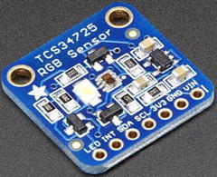
Figure 6-2. Adafruit RGB Sensor (courtesy of adafruit.com)
Wiring the breakout board is also very easy since we need only power, ground, SCL and SDA connections. SCL is the clock signal, and SDA is the data signal. These pins are labeled on your MicroPython board (or in the documentation) as well as the breakout board. When you connect your breakout board, make sure the power requirements match. That is, some breakout boards can take 5V but many are limited to 3 or 3.3V. Check the vendor’s website if you have any doubts.
We need only to connect the 3V, ground, SDA, SCL, and LED pins. The LED pin is used to turn on the bright LED on the breakout board to signal it is ready to read. We will leave it on for 10 seconds so that there is time to read the color value then display it. We will then wait another 5 seconds to take the next reading.
To connect the wires, you can use five male-to-female jumper wires to plug into the WiPy (or Expansion Board) and the breakout board. Figure 6-3 shows the connections you need to make. Notice the wires are plugged into pins marked as “GXX” rather than “PinXX.” This can be a source of confusion when working with boards. It is always best to refer to the pinout drawings to ensure you’re using the right pins. In this case, we need P9 and P10 for the I2C connection and we will use P8 for the LED.
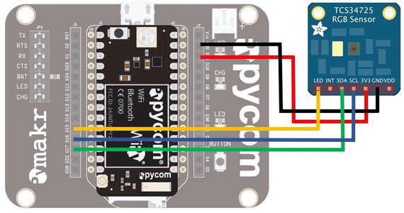
Figure 6-3. Wiring the RBG Sensor (WiPy)
Tip
See https://docs.pycom.io/chapter/datasheets/development/wipy2.html for the pinouts for the WiPy board and https://docs.pycom.io/chapter/datasheets/boards/expansion.html for the Expansion Board. Note that the Expansion board “mirrors” the WiPy, but its labels are completely different.
Once you have the hardware connected, set it aside. We need to download the driver and copy it to the board before we can experiment further. You can find the driver at https://github.com/adafruit/micropython-adafruit-tcs34725 . This is a fully working, tested driver that demonstrates how easy it is to use an I2C breakout board. Don’t worry about the internals of the library.5 The code to which I’m referring is shown below. Notice the default address is 0x29 but since address is a parameter, you can override it if you have another breakout board for the same RGB sensor that is at a different address. This means you can use more than one with the same driver .
class TCS34725:def __init__(self, i2c, address=0x29):self.i2c = i2cself.address = addressself._active = Falseself.integration_time(2.4)sensor_id = self.sensor_id()if sensor_id not in (0x44, 0x10):raise RuntimeError("wrong sensor id 0x{:x}".format(sensor_id))...
To download the driver, you first navigate to https://github.com/adafruit/micropython-adafruit-tcs34725 and then click the Download button and then the Download Zip button. Once the file has downloaded, unzip it. In the resulting folder, you should find the file named tcs34725.py. This is the driver code module. When ready, we will copy it to our WiPy using FTP as shown below. Be sure to connect to your WiPy Wi-Fi network first and open a terminal in the same directory as the file.
$ ftp 192.168.4.1Connected to 192.168.4.1.220 Micropython FTP ServerName (192.168.4.1:cbell): microPassword:Remote system type is UNIX.Using binary mode to transfer files.ftp> cd flashftp> put tcs34725.pylocal: tcs34725.py remote: tcs34725.py227 (192,168,4,1,7,232)100% |***********************************| 5222 23.05 MiB/s 00:00 ETA5222 bytes sent in 00:00 (6.57 KiB/s)ftp> quit
Now that the driver is copied to our board, we can write the code. In this example, we will set up the I2C connection to the breakout board and run a loop to read values from the sensor. Sounds simple, but there is a bit of a trick to it. We will forego a lengthy discussion of the code and instead offer some key aspects allowing you to read the code yourself to see how it works.
The key components are setting up the I2C, sensor, a pin for controlling the LED, and reading from the sensor. The LED on the board can be turned on and off by setting a pin high (on) or low (off). First, the I2C code is as follows. Here, we initiate an object, then call the init() function setting the bus to master mode. The scan() function prints out the devices on the bus. If you see an empty set displayed, your I2C wiring is not correct. Check it and try the code again. Note that you can run this code manually once you’ve done the imports.
i2c = I2C(0, I2C.MASTER) # create and init as a masteri2c.init(I2C.MASTER, baudrate=20000) # init as a masteri2c.scan()
The next part is the sensor itself. The driver makes this easy. All we need to do is pass in the I2C constructor function as shown.
# Setup the sensorsensor = tcs34725.TCS34725(i2c)
Setting up the LED pin is also easy. All we need to do is call the Pin() class constructor passing in the pin name (P8) and setting it for output mode as follows.
# Setup the LED pinled_pin = Pin("P8", Pin.OUT)led_pin.value(0)
Finally, we read from the sensor with the sensor.read() function passing in True, which tells the driver to return the RGBC values. We will then print these out in order. Listing 6-6 shows the completed code. Take a few moments to read through it so that you understand how it works.
Listing 6-6. Using the Adafruit RGB Sensor (WiPy)
# MicroPython for the IOT - Chapter 6# Example of using the I2C interface via a driver# for the Adafruit RGB Sensor tcs34725## Requires library:# https://github.com/adafruit/micropython-adafruit-tcs34725#from machine import I2C, Pinimport sysimport tcs34725import utime# Method to read sensor and display resultsdef read_sensor(rgb_sense, led):sys.stdout.write("Place object in front of sensor now...")led.value(1) # Turn on the LEDutime.sleep(5) # Wait 5 secondsdata = rgb_sense.read(True) # Get the RGBC valuesprint("color detected: {")print(" Red: {0:03}".format(data[0]))print(" Green: {0:03}".format(data[1]))print(" Blue: {0:03}".format(data[2]))print(" Clear: {0:03}".format(data[3]))print("}")led.value(0)# Setup the I2C - easy, yes?i2c = I2C(0, I2C.MASTER) # create and init as a masteri2c.init(I2C.MASTER, baudrate=20000) # init as a masteri2c.scan()# Setup the sensorsensor = tcs34725.TCS34725(i2c)# Setup the LED pinled_pin = Pin("P8", Pin.OUT)led_pin.value(0)print("Reading Colors every 10 seconds. When LED is on, place object in front of sensor.")print("Press CTRL-C to quit. (wait for it)")while True:utime.sleep(10) # Sleep for 10 secondsread_sensor(sensor, led_pin) # Read sensor and display values
Once you have the code , you can copy it to your board in the similar manner we did for the driver with the ftp utility as shown below.
$ ftp 192.168.4.1Connected to 192.168.4.1.220 Micropython FTP ServerName (192.168.4.1:cbell): microPassword:Remote system type is UNIX.Using binary mode to transfer files.ftp> cd flashftp> put wipy_RGB.pylocal: wipy_RGB.py remote: wipy_RGB.py227 (192,168,4,1,7,232)100% |***********************************| 1202 4.51 MiB/s 00:00 ETA1202 bytes sent in 00:00 (2.17 KiB/s)ftp> quit
All that is left is running the example and testing it. Listing 6-7 shows how you can run the example on the WiPy as well as a sample of the output. If you are running this example on your WiPy, you can place whatever object you want in front of the sensor, and it will read the color returning it as a tuple representing the RGB value plus clear values as shown.
Listing 6-7. Output from using the Adafruit RGB Sensor (WiPy)
>>> import wipy_RGBReading Colors every 10 seconds. When LED is on, place object in front of sensor.Press CTRL-C to quit. (wait for it)Place object in front of sensor now...color detected: {Red: 057Green: 034Blue: 032Clear: 123}Place object in front of sensor now...color detected: {Red: 054Green: 069Blue: 064Clear: 195}Place object in front of sensor now...color detected: {Red: 012Green: 013Blue: 011Clear: 036}...
If you wanted another exercise, you could take these values from the sensor and map them to an RGB LED. Yes, you can do that! Go ahead, try it. See https://github.com/JanBednarik/micropython-ws2812 for inspiration. Tackle it after you’ve read the next section on SPI.
Tip
See https://learn.sparkfun.com/tutorials/i2c for an in-depth discussion of I2C.
Serial Peripheral Interface (SPI)
The Serial Peripheral Interface (SPI) is designed to allow sending and receiving data between two devices using a dedicated line for each direction. That is, it uses two data lines along with a clock and a slave select pin. Thus, it requires six connections for bidirectional communication or only five for reading or writing only. Some SPI devices may require a seventh pin called a reset line.
Let’s look at an example of how to use a SPI breakout board. In this example, we want to use the Adafruit Thermocouple Amplifier MAX31855 breakout board ( https://www.adafruit.com/product/269 ) and a Thermocouple Type-K sensor ( https://www.adafruit.com/product/270 ) to read high temperatures. We will use this breakout board with a Pyboard.
Don’t worry if you do not have or do not want to purchase the Adafruit Thermocouple Amplifier MAX31855 breakout board (although it is not expensive). This example is provided as a tutorial for working with SPI breakout boards. We will use another I2C breakout board in one of the example projects later in the book. Figure 6-4 shows the Adafruit Thermocouple Amplifier and Type-H sensor from Adafruit.
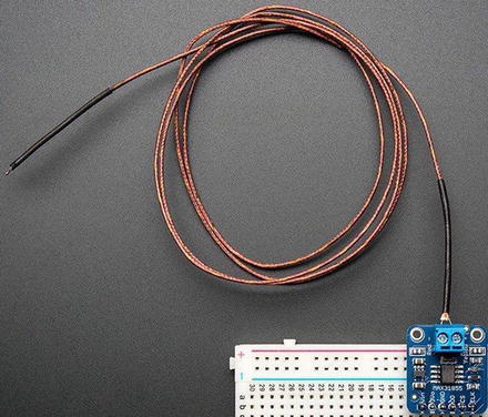
Figure 6-4. Adafruit Thermocouple Breakout Board and Type-K Sensor (courtesy of adafruit.com)
The sensor can be used to measure high temperatures either through proximity or touch. The sensor can read temperature in the range -200°C to +1350°C output in 0.25 degree increments. One possibly use of this sensor is to read the temperature of nozzles on 3D printers or any similar high heat output. It should noted that the breakout board comes unassembled so you will need to solder the header and terminal posts .
Now, let’s see how to wire the breakout board to our Pyboard. We will use only five wires since we are only reading data from the sensor on the breakout board. This requires a connection to power (ground (GND), the master input (MOSI), clock (CLK), and slave select (SS). Figure 6-5 shows the connections.
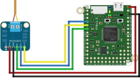
Figure 6-5. Wiring the Adafruit Thermocouple Module (Pyboard)
The correct pins to use on the Pyboard are shown in Table 6-2. You can find these pins on the Pyboard pinout found at https://docs.micropython.org/en/latest/pyboard/pyboard/quickref.html . Refer to Figure 6-5 for confirmation.
Table 6-2. Connecting the Thermocouple Breakout Board (Pyboard )
Pyboard | Location on Pyboard | Breakout board |
|---|---|---|
VIN | upper rightmost pin | 3V0 |
GND | on right side, third pin down from the top | GND |
Y5 | on left side of the board, fifth pin from top | CS (slave select) |
Y6 | on left side of the board, sixth pin from top | CLK |
Y7 | on left side of the board, seventh pin from top | D0 |
Now, let’s look at the code! In this example, we are not going to use a driver; rather, we’re going to see how to read directly from the breakout board using SPI. To do so, we first set up an object instance of the SPI interface then choose a pin to use for slave select (also called chip or even code select). From there, all we need to do is read the data and interpret it. We will read the sensor in a loop and write a function to convert the data.
This is the tricky part. This example shows you what driver authors must do to make using the device easier. In this case, we must read the data from the breakout board and interpret it. We could just read the raw data, but that would not make any sense since it is in binary form. Thus, we can borrow some code from Adafruit that reads the raw data and makes sense of it.
The function is named normalize_data() and it does some bit shifting and arithmetic to transform the raw data to a value in Celsius. This information comes from the datasheet for the breakout board but the nice folks at Adafruit made it easy for us.
Setting up the SPI class is easy. We initiate an SPI object using the class constructor passing in the SPI option. This is unique to the Pyboard and can be values of 1 – use the X position, or 2 – use the Y position. Notice in the connections above we use the Y-pins so we will use a value of 2 for the first parameter. The other parameters tell the SPI class to set up as a master, set the baudrate, polarity, and phase (which can be found on the datasheet). Next, we need only select the pin for reading data and then set the pin high. The following shows the code we need to activate the SPI interface.
spi = SPI(2, SPI.MASTER, baudrate=5000000, polarity=0, phase=0)cs = machine.Pin("Y5", machine.Pin.OUT)cs.high()
Now, let’s look at the completed code . Listing 6-8 shows the complete code to use the Thermocouple Amplifier Breakout board from Adafruit.
Listing 6-8. The Adafruit Thermocouple Module Example (Pyboard)
# MicroPython for the IOT - Chapter 6# Simple example for working with the SPI interface# using the Adafruit Thermocouple Amplifier. See# https://www.adafruit.com/product/269.## Note: this only runs on the Pyboard#import machineimport ubinascii# First, make sure this is running on a Pyboardtry:import pybfrom pyb import SPIexcept ImportError:print("ERROR: not on a Pyboard!")sys.exit(-1)# Create a method to normalize the data into degrees Celsiusdef normalize_data(data):temp = data[0] << 8 | data[1]if temp & 0x0001:return float('NaN')temp >>= 2if temp & 0x2000:temp -= 16384return (temp * 0.25)# Setup the SPI interfaceon the "Y" interfacespi = SPI(2, SPI.MASTER, baudrate=5000000, polarity=0, phase=0)cs = machine.Pin("Y5", machine.Pin.OUT)cs.high()# read from the chipprint("Reading temperature every second.")print("Press CTRL-C to stop.")while True:pyb.delay(1000)cs.low()print("Temperature is {0} Celsius.".format(normalize_data(spi.recv(4))))cs.high()
At this point, you can make the hardware connections and power on your Pyboard. Then, you can copy the file to your Pyboard and execute it as shown below.
>>> import pyboard_SPIReading temperature every second.Press CTRL-C to stop.Temperature is 32.0 Celsius.Temperature is 31.75 Celsius.Temperature is 32.0 Celsius.Temperature is 32.5 Celsius.Temperature is 33.5 Celsius.Temperature is 34.0 Celsius.Temperature is 34.25 Celsius.Temperature is 34.5 Celsius.Temperature is 34.5 Celsius....
Once you run the example, you should see it produce values in degrees Celsius. If you see 0.00, you likely do not have the SPI interface connected properly. Check your wiring against the figure above. If you see values but they go down when you expose the thermocouple tip to heat, you need to reverse the wires. Be sure to power off the board first to avoid damaging the sensor, breakout board, or your Pyboard!
If you would like to run this example with the WiPy, you can! Simply alter the code to use the WiPy SPI class and its initialization sequence as shown at https://docs.pycom.io/chapter/firmwareapi/pycom/machine/SPI.html . You will also have to change the includes a bit, but this is good practice for the example project chapters.
Tip
See https://learn.sparkfun.com/tutorials/serial-peripheral-interface-spi for an in-depth discussion of SPI.
Summary
Accessing the low-level hardware through the firmware is where the true elegance and in some cases complexity of using MicroPython begins. Given that the available boards differ, it should be no surprise that the low-level support in the firmware also differs. Thus, when planning MicroPython IOT projects, we must consider what we want to do and whether our board (and firmware) supports it. We also need to know what breakout boards and devices we want to connect to and if there are drivers or other libraries we can use to access them. In this case, most breakout boards with I2C or SPI interfaces will require some form of driver.
In this chapter, we explored some of the low-level support in the firmware and specialized support for the Pyboard and WiPy. As we discovered, this is where the code becomes very specialized. As we saw, it sometimes is a matter of choosing a different library to import, but sometimes the classes, functions, and even how to use the functions differs from one board to another.
We also saw a lot of code in this chapter – more than any previous chapter. The examples in this chapter are meant to be examples for you to see how things are done rather than projects to implement on your own (although you’re welcome and encouraged to do so). We will see more hands-on projects with a greater level of detail in later chapters.
In the next chapter, we take a short detour in the form of a short tutorial on electronics. If you’ve never worked with electronics before, the next chapter will give you the information you need to complete the projects in this book and prepare you for an exciting new hobby – building MicroPython IOT projects!
Footnotes
3 Whenever you find yourself making functions for commonly used code, it is time to consider adding it to a library of your favorite functions to make the code available for all your programs as we discussed in Chapter 5.
4 No, I am not affiliated with either of these – merely a devoted fan and frequent return customer. Check them out!
5 But feel free if you are curious. If you do, you will see an interesting bit of code that demonstrates the addressability of I2C devices.