
If you are new to working with hardware and have little or no experience with electronics, you may be curious as to how you can complete the projects in this book. Fortunately, the projects in this book walk you through how to connect the various electronic parts together with your MicroPython board. That is, you can complete the projects without additional skill or experience.
However, if you want to know what the components do, you will need a bit more information than “plug this end in here.” This is especially so if something goes wrong. Furthermore, if you want to create projects on your own, you need to know enough about how the components work to successfully complete your project – whether that is completing the examples in this book or examples found elsewhere on the Internet.
Fortunately, you don’t need formal training or even a college degree in theory to learn how to work with electronics. You can learn quite a lot about working with electronics at the hobbyist level without devoting months or years of research.1 To ensure success even at a basic level, you will need to know more than simply how to plug the components together.
Rather than attempt to present a comprehensive tutorial on electronics, which would take several volumes, this chapter presents an overview of electronics for those who want to work with the types of electronic components commonly found in IOT projects. I include an overview of some of the basics, descriptions of common components, and a look at sensors. If you are new to electronics, this chapter will give you the extra boost you need to understand the components used in the projects in this book.
If you have experience with electronics either at the hobbyist or enthusiast level or have experience or formal training in electronics, you may want to skim this chapter or read the sections with topics on which you may want a refresher.
Let’s begin with a look at the basics of electronics. Once again, this is in no way a tutorial that covers all there is to know, but it will get you to the point where the projects make sense in how they connect and use components.
The Basics
This section presents a short overview of some of the most common tools and techniques you will need to use when working with electronics. As you will see, you only need the most basic of tools and the skills or techniques are not difficult to learn. However, before we get into those, let’s look at some of the tools you will need to work on your IOT projects.
Tools
The clear majority of tools you will need to construct your IOT projects are common hand tools (screwdrivers, small wrenches, pliers, etc.). For larger projects or for creating enclosures you may need additional tools such as power tools, but I will concentrate only on those tools for building the projects. The following is a list of tools I recommend to get you started.
Breadboard
Breadboard wires (also called jumpers)
Electrostatic discharge (ESD) safe tweezers
Helping hands or printed circuit board (PCB) holder
Multimeter
Needle-nose pliers
Screwdrivers – assorted sizes (micro, small)
Solder
Soldering iron
Solder remover (solder sucker)
Tool case, roll, or box for storage
Wire strippers
However, you cannot go wrong if you prefer to buy a complete electronics toolset such as those from Sparkfun (sparkfun.com/categories/47) or Adafruit (adafruit.com/categories/83). You can often find electronics kits at major brand electronics stores and home improvement centers. If you are fortunate enough to live near a Fry’s Electronics, you can find just about any electronics tool made. Most electronics kits will have all the hand tools you will need. Some even come with a multimeter but more often you must buy them separately.
Most of the tools in the list do not need any explanation except to say you should purchase the best tools that your budget permits. The following paragraphs describe some of the tools that are used for special tasks such as stripping wires, soldering, and measuring voltage and current.
Multimeter
A multimeter is one of those tools that you will need when building IOT solutions. You will also need it to do almost any electrical repair on your circuits. There are many different multimeters available with prices ranging from inexpensive, basic units; to complex, feature-rich, incredibly expensive units. For most IOT projects, including most IOT kits, a basic unit is all you will need. However, if you plan to build more than one IOT solution or want to assemble your own electronics, you may want to invest a bit more in a more sophisticated multimeter. Figure 7-1 shows a basic digital multimeter (costing about $10) on the left and a professional multimeter from BK Precision on the right.

Figure 7-1. Digital multimeters
Notice the better meter has more granular settings and more features. Again, you probably won’t need more than the basic unit. You will need to measure voltage, current, and resistance at a minimum. Whichever meter you buy, make sure it has modes for measuring AC and DC voltage, continuity testing (with an audible alert), and checking resistance. I will explain how to use a multimeter in a later section.
Tip
Most multimeters including the inexpensive ones come with a small instruction booklet that shows you how to measure voltage, resistance, and other functions of the unit.
Soldering Iron
A soldering iron is not required for any of the projects in this book because we will use a breadboard to lay out and connect the components. However, if you plan to build a simple IOT solution where you will need to solder wires together, or maybe a few connectors, a basic soldering iron from an electronics store such as Radio Shack is all you will need. On the other hand, if you plan to assemble your own electronics, you may want to consider getting a good, professional soldering iron such as a Hakko. The professional models include features that allow you to set the temperature of the wand, have a wider array of tips available, and tend to last a lot longer. Figure 7-2 shows a well-used entry-level one from Radio Shack. Figure 7-3 shows a professional model Hakko soldering iron.
Tip
For best results, choose a solder with a low lead content in the 37%–40% range. If you use a professional soldering iron, adjust the temperature to match the melting point of the solder (listed on the label).
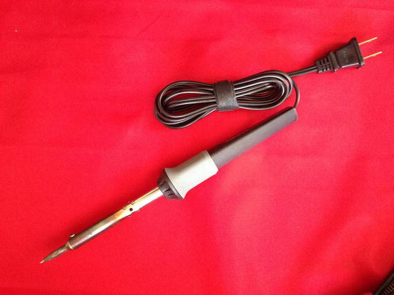
Figure 7-2. Entry-level soldering iron
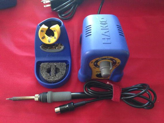
Figure 7-3. Professional soldering iron
Wire Strippers
There are several types of wire strippers. In fact, there are probably a dozen or more designs out there. But there are two kinds: ones that only grip and cut the insulation as you pull it off the wire; and those that grip, cut, and remove the insulation. The first type is more common and, with some practice, does just fine for most small jobs (like repairing a broken wire); but the second type makes a larger job — such as wiring electronics from bare wire (no prefab connectors) — much faster. As you can imagine, the first type is considerably cheaper. Figure 7-4 shows both types of wire strippers. Either is a good choice.

Figure 7-4. Wire strippers
Helping Hands
There is one other tool that you may want to get, especially if you need to do any soldering: it’s called helping hands or third hand tool. Most have a pair of alligator clips to hold wires, printed circuit boards, or components while you solder. Figure 7-5 shows an example of a simple helping hands tool.

Figure 7-5. Helping hands tool
Now let’s look at some of the skills you are likely to need when working with advanced IOT projects.
Let’s look at how to use the one tool you will likely use more than any other when learning electronics - the multimeter.
Using a Multimeter
The electrical skills needed for IOT projects can vary from plugging in wires on a breadboard — as we saw with the projects so far — to needing to solder components together or to printed circuit boards (PCBs) . Regardless of whether you need to solder the electronics, you will need to be able to use a basic multimeter to measure resistance and check voltage and current.
A multimeter is a very useful and essential tool for any electronics hobbyist and downright required for any enthusiast of worth. A typical multimeter has a digital display2 (typically an LCD or similar numeric display), a dial, and two or more posts or ports for plugging in test leads with probe ends. Most multimeters have ports for lower current (that you will use most) and ports for larger current. Test leads use red for positive and black for negative (ground). The ground port is where you plug in the black test lead and is often marked with a dash or COM for common. Which of the other ports you use will depend on what you are testing.
One thing to note on the dial is that there are many settings (with some values repeated) or those that look similar. For example, you will see a set of values (sometimes called a scale) for ohms, one or two set of values for amperage, and one or two set of values for volts. The set of values for voltages that has a V with a solid and dashed line is for DC whereas the range that has a V with a wavy line is for AC. Amperage ranges are marked in the same manner. Figure 7-6 shows a close-up of a multimeter dial labeled with the sets of values I’ve mentioned.

Figure 7-6. Multimeter Dial (typical)
Tip
When not in use, be sure to turn your multimeter dial to off or one of the voltage ranges if it has a separate off button.
There is a lot you can do with a multimeter. You can check voltage, measure resistance, and even check continuity. Most basic multimeters will do these functions. However, some multimeters have a great many more features such as testing capacitors and the ability to test AC as well as DC.
Let’s see how we can use a multimeter to perform the most common tasks we will need for IOT projects: testing continuity, measuring voltage in a DC circuit, measuring resistance, and measuring current.
Testing Continuity
We test for continuity to determine if there is a path for the charged particles to flow: that is, our wires and components are connected properly. For example, you may want to check to ensure a wire has been spliced correctly.
To test for continuity, turn your multimeter dial to the position marked with an audible symbol, bell, or triangle with an arrow through it. Plug the black test lead into the COM port and the red test lead in the port marked with Hz VΩ or similar. Now you can touch the probe end of the test leads together to hear an audible tone or beep. Some multimeters don’t have an audible tone but instead may display “1” or the like to indicate continuity. Check your manual for how your multimeter indicates continuity. Figure 7-7 shows how to set a multimeter to check for continuity including which ports to plug in the test leads.
Notice in the photo I simply touched the probes together to demonstrate how to check for continuity. I like to do this just to ensure my multimeter is turned on and on the correct setting.3
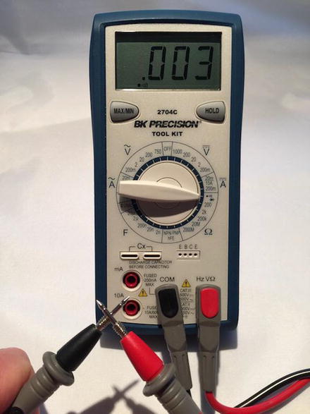
Figure 7-7. Settings for checking continuity
Another excellent use for the continuity test is when diagnosing or discovering how cables are wired. For example, you can use the continuity test to discover which connector is connected on each end of the cable (sometimes called wire sorting or ringing out from the old telephone days).
Measuring Voltage
Our IOT projects use DC. To measure voltage in the circuit, we will use the DC range on the multimeter. Notice the DC range has several stops. This is a scale selection. Choose the scale that closely matches the voltage range you want to test. For example, for our IOT projects we will often measure 3.3-12V so we choose 20 on the dial. Next, plug the black test lead into the COM port and the red test lead into the port labeled Hz VΩ.
Now we need something to measure! Take any battery you have in the house and touch the black probe to the negative side and the red probe to the positive side. You should see a value appear on the display that is close to the range for the battery. For example, if we used a 1.5V battery, we should see close to 1.5V. It may not be exactly 1.5-1.6V if the battery is depleted. So now you know how to test batteries for freshness! Figure 7-8 shows how to measure voltage of a battery.
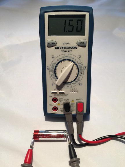
Figure 7-8. Measuring voltage of a battery
Notice the readout displays 1.50, which is the correct voltage for this AA battery. If I had reversed the probes – the red one on negative and the black on positive, the display would have read -1.50. This is Ok because it shows the current is flowing in the opposite direction of how the probes are oriented.
Note
If you use the wrong probe when measuring voltage in a DC circuit, most multimeters will display the voltage as a negative number. Try that with your battery. It won’t hurt the multimeter (or the battery)!
We can use this technique to measure voltage in our projects. Just be careful to place the probes on the appropriate positions and try not to cross or short by touching more than one component at a time with a single probe tip.
Measuring Current
Current is measured as amperage (milliamps - mA). Thus, we will use the range marked with an A with a straight and dashed line (not the wavy one - that’s AC). We measure current in series. That is, we must place the multimeter in the circuit. This can be a little tricky because we must interrupt the flow of current and put the meter inline.
If you are familiar with how to use a breadboard, you can follow along with this experiment. However, if you haven’t used a breadboard, you may want to read through this experiment, then return to it once you finish reading this chapter. For this experiment, we will use a breadboard power supply, an LED, and a resistor. We will wire the circuit such that we will use the multimeter to complete the circuit. Figure 7-9 shows how to set up the circuit with the multimeter inline.

Figure 7-9. Measuring current
Before powering on your breadboard power supply, plug the black test lead into the COM port and the other test leads into the port labeled mA. Some multimeters use the same port for measuring voltage as well as current. Turn the dial on the multimeter to the 200mA setting. Then power on the breadboard power supply and touch the leads to the places indicated. Be careful to touch only the VCC pin on the breadboard power supply. Once the circuit is powered on, you should see a value on the multimeter. Figure 7-10 shows how to use a multimeter to measure current in a circuit

Figure 7-10. Measuring current
There is one other tricky thing about measuring current. If you attempt to measure current that is greater than the maximum for the port (for example, the meter in the photo has a maximum of 20mA on the one port). If I exceeded that by, say 5A, I would likely blow a fuse in the multimeter. This is not desirable but at least there is a fuse that we can replace should we make a mistake and choose the wrong port.
Measuring Resistance
Resistance is measured in ohms (Ω). The most common component we will use to introduce resistance in a circuit is a resistor. We can test the resistance of the charge through the resistor with our multimeter. To test resistance, choose the ohm scale that is closest to the rating of the resistor. For example, I am going to test a resistor that I believe is about 200 ohms but since I am not sure, I will choose the 2k setting.
Next, plug the black test lead into the COM port and the red test lead into the port labeled HzVΩ. Now, touch one probe to one side of a resistor and the other probe to the other side. It doesn’t matter which side you choose – a resistor works in both directions. Notice the readout. The meter will read one of three things: 0.00, 1, or the actual resistor value.
In this case, the meter reads 0.219, meaning this resistor has a value of 220Ω. Recall, I used the 2k scale, which means a resistor of 1k would read 1.0. Since the value is a decimal, I can move the decimal point to the left to get a whole number.
If the multimeter displays another value such as 0 or 1, it indicates the scale is wrong and you should try a higher scale. This isn’t a problem. It just means you need to choose a larger scale. On the other hand, if the display shows 0 or a small number, you need to choose a lower scale. I like to go one tick of the knob either way when I am testing resistance in an unknown component or circuit.
Figure 7-11 shows an example of measuring resistance for a resistor. Notice the display reads 219. I am testing a resistor rated at 220 ohms. The reason it is 219 instead of 220 is because the resistor I am using is rated at 220 +/- 5%. Thus, the acceptable range for this resistor is 209-231 ohms.

Figure 7-11. Measuring resistance of a resistor
Now we know how to test a resistor to discover its rating. As we will see, those rings around the body of the resistor are the primary way we know its rating but we can always test it if we’re unsure, someone has painted over it (hey, it happens), or we’re too lazy to look it up.
Now, let’s discuss the most fundamental concept you must understand when working with electronics – powering your project!
Powering Your Electronics
Electricity4 is briefly defined as the flow of electric charge and when used provides power for our electronics – from a common light bulb or ceiling fan to our high definition television or our new tablet. Whether you are powering your electronics with batteries or a power supply, you are initiating a circuit where electrons flow in specific patterns. There are two forms (or kinds) of power you will be using. Your home is powered by alternating current and your electronics are powered by direct current.
The term alternating current (AC) is used to describe the flow of charged particles that changes direction periodically at a specific rate (or cycle) reversing the voltage along with the current. Thus, AC systems are designed to work with a specific range of cycles as well as voltage. Typically, AC systems use higher voltages than direct current systems.
The term direct current (DC) is used to describe the flow of charged particles that do not change direction and thus always flow in a specific “direction.” Most electronics systems are powered with DC voltages and are typically at lower voltages than AC systems. For example, IOT projects typically run on lower direct current (DC) voltages in the range 3.3-24V.
Tip
For more information about AC and DC current and the differences, see https://learn.sparkfun.com/tutorials/alternating-current-ac-vs-direct-current-dc .
Since DC flows in a single direction, components that operate on DC have a positive and negative “side” where current flows from positive to negative. The orientation of these sides – one to positive and one to negative is called polarity. Some components such as resistors can operate in either “direction” but you should always be sure to connect your components per its polarity. Most components are clearly marked but those that are not have a well-known arrangement. For example, the positive pole (side) of an LED is the longer of the two legs (called anode whereas the negative or shorter leg is called the cathode ).
Despite the lower voltages, we mustn’t think that they are completely harmless or safe. Incorrectly wiring electronics (reversing polarity) or shorting (connecting positive and negative together) can damage your electronics and in some cases cause overheating, which, in extreme cases, causes electronics to catch fire.
Caution
Don’t be tempted to think working with 3.3 or 5.5 volts is “safe.” Even a small amount of voltage improperly connected can lead to potentially devastating results. Don’t assume low DC voltage is harmless.
I had a lesson in just how real this scenario can be a couple of years ago. I was changing the batteries in our smoke detectors. I took the old batteries out and placed them in my pocket. I had forgotten I had a small penknife in the same pocket. One of the batteries shorted on the knife and within about ten minutes, the battery heated to an alarming temperature. It wasn’t enough to burn but had I left something like that unattended, it could have been bad.
That’s a scary thought, isn’t it? Consider it an admonishment as well as a warning; we should never relax our safe handling practices even for lower voltage projects.
Finally, DC components are often rated for a specific voltage range. Recall from our discussion on the various low-cost computing boards and GPIO headers, some boards operate at 5V whereas others operate at 3.3V (or less). Fortunately, there are several ways we can adapt components that work at different voltages – by using other components!
Note
I have deliberately kept the discussion on power simple. There is far more to electrical current – even DC – than what I’ve described here. Once you understand these basics, you’ll be able to work with the projects in this book and more.
Electronic Components
Aside from learning how to use a multimeter and possibly learning to solder, you also need to know something about the electronic components available to build your projects. In this section, I provide a short list and description of some of the common components in alphabetical order by name that you will encounter when building IOT solutions. I also cover breakout boards and logic circuits, which are small circuits built with a set of components that provide a feature or solve a problem. For example, you can get breakout boards for USB host connections, Ethernet modules, logic shifters, real-time clocks, and more.
Button
A button (sometimes called a momentary button) is a mechanism that makes a connection when pressed. More specifically, a button connects two or more poles together while it is pressed. A common (and perhaps overused) example of a button is a home doorbell. When pressed, it completes a circuit that triggers a chime, bell, tone, or music to play. Some older doorbells continue to sound while the button is pressed.
In IOT projects, we will use buttons to trigger events, start and stop actions, and similar operations. A button is a simple form of a switch but unlike a switch, you must continue to press the button to make the electrical connections. Most buttons have at least two legs (or pins) that are connected when the button is pressed. Some have more than two legs connected in pairs and some of those can permit multiple connections. Figure 7-12 shows several buttons.

Figure 7-12. Momentary buttons
There is a special variant of a momentary button called a latching momentary button. This version uses a notch or detent to keep the poles connected until it is pushed again. If you’ve seen a button on a stereo or in your car that remains depressed until pressed again, it is likely a latching momentary button.
There are all kinds of buttons from those that can be used with breadboards (the spacing of the pins allow it to be plugged into a breadboard), can be mounted to a panel, or those made for soldering to printed circuit boards.
Capacitor
A capacitor is designed to store charges. As current flows through the capacitor, it accumulates charge and can discharge after the current is disconnected. In this way, it is like a battery but unlike a battery, a capacitor charges and discharges very fast. We use capacitors for all manner of current storage from blocking current, reducing noise in power supplies, in audio circuits, and more. Figure 7-13 shows several capacitors.
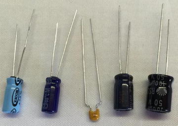
Figure 7-13. Capacitors
There are several types of capacitors but we will most often encounter capacitors when building power supplies for IOT projects. Most capacitors have two legs (pins) that are polarized. That is, one is positive and the other negative. Be sure to connect the capacitor with the correct polarity in your circuit.
Diode
A diode is designed to allow current to flow in only one direction. Most are marked with an arrow pointing to a line, which indicates the direction of flow. A diode is often used as rectifiers in AC-to-DC converters (devices that convert AC to DC voltage), used in conjunction with other components to suppress voltage spikes, or protect components from reversed voltage. They are often used to protect against current flowing into a device.
Most diodes are shaped like a small cylinder, and they are usually black with silver writing and have two legs. They look a little like resistors. We use a special variant called a Zener diode in power supplies to help regulate voltages. Figure 7-14 shows several Zener diodes.
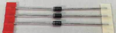
Figure 7-14. Diodes
Fuse
A fuse is designed to protect a device (the entire circuit) from current greater than what the components can safely operate. Fuses are placed inline on the positive pole. When too much current flows through the fuse, the internal parts trigger a break in the flow of current.
Some fuses use a special wire inside that melts or breaks (thereby rendering it useless but protecting your equipment) while other fuses use a mechanism that operates like a switch (many of these are resettable). When this happens, we say the fuse has “blown” or “tripped.” Fuses are rated at a certain current in amperage indicating the maximum amps that the fuse will permit to flow without tripping.
Fuses come in many shapes and varieties and can work with AC or DC voltage. Those we will use are of the disposable variety. Figure 7-15 shows an example of two fuses: an automotive-style blade fuse on the left and a glass cartridge fuse on the right.
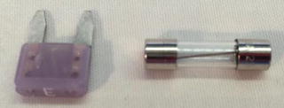
Figure 7-15. Fuses
If you are familiar with the electrical panel in your home that house the circuit breakers, they are resettable fuses. So, the next time one of them goes “click” and the lights go out, you can say, “Hey, a fuse has tripped!” Better still, now you know why - you have exceeded the maximum rating of the circuit breaker.
This is probably fine in situations where you accidentally left that infrared heater on when you dropped the toast and started the microwave (it happens), but if you are tripping breakers frequently without any load, you should call an electrician to have the circuit checked.
Light Emitting Diode (LED)
As we learned in Chapter 3, an LED has two legs where the longer leg is positive and the shorter negative. LEDs also have a flat edge that indicates the negative leg. They come in a variety of sizes ranging from as small as 3mm to 10mm. Figure 7-16 shows an example of some smaller LEDs.
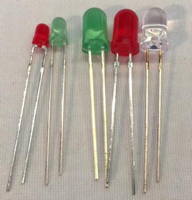
Figure 7-16. Light emitting diodes
Recall we also needed to use a resistor with an LED. We need this to help reduce the flow of the circuit to lower the current flowing through the LED. LEDs can be used with lower current (they will burn a bit dimmer than normal) but should not be used with a higher current.
To determine what size resistor we need, we need to know several things about the LED. This data is available from the manufacturer who provides the data in the form of a datasheet or in the case of commercially packaged products, lists the data on the package. The data we need includes the maximum voltage, the supply voltage (how many volts are coming to the LED), and the current rating of the LED.
For example, if I have an LED like the one we used in the last chapter, in this case a 5mm red LED, we find on Adafruit’s website (adafruit.com/products/297) that the LED operates at 1.8-2.2V and 20mA of current. Let’s say we want to use this with a 5V supply voltage. We can then take these values and plug them into this formula5:
R = (Vcc-Vf)/IUsing more descriptive names for the variable, we get the following.
Resistor = (Volts_supply - Volts_forward) / Desired_currentPlugging our data in, we get this result. Note that we have mA so we must use the correct decimal value (divide by 1000). In this case, it is 0.020 and we will pick a voltage in the middle.
Resistor = (5 - 2.0) / 0.020= 3.0 / 0.020= 150
Thus, we need a resistor of 150 ohms. Cool. Sometimes the formula will produce a value that does not match any existing resistors. In that case, choose one closest to the value but a bit larger. Remember, we want to limit and thus err on the side of more restrictive than less restrictive. For example, if you found you need a resistor of 95 ohms, you can use one rated at 100 ohms, which is safer than using one rated at 90 ohms.
Tip
Always err on the side of the more restrictive resistor when the formula produces a value for which there is no resistor available.
Also, if you use LEDs in serial or parallel, the formula is a little different. See https://learn.adafruit.com/all-about-leds for more information about using LEDs in your projects and calculating the size of resistors to use with LEDs.
Relay
A relay is an interesting component that helps us control higher voltages with lower voltage circuits. For example, suppose you wanted to control a device that is powered by 12V from your MicroPython board, which only produces a maximum of 3V. A relay can be used with a 3V circuit to turn on (or relay) power from that higher source. In this example, we would use the MicroPython board output to trigger the relay to switch on the 12V power. Thus, relays are a form of switch. Figure 7-17 shows a typical relay and how the pins are arranged.
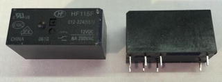
Figure 7-17. Relay
Relays can take a lot of different forms and typically have slightly different wiring options such as where the supply voltage is attached and where the trigger voltage attaches as well as whether the initial state is open (no flow) or close (flow) and thus the behavior of how it controls voltage. Some relays come mounted on a PCB with clearly marked terminals for changing its switching feature and where everything plugs in. If you want to use relays in your projects, always check the datasheet to make sure you are wiring it correctly based on its configuration.
You can also use relays to allow your DC circuit to turn AC appliances on and off like those from Adafruit ( https://www.adafruit.com/product/2935 ).
Resistor
A resistor is one of the standard building blocks of electronics. Its job is to impede current and impose a reduction in voltage (which is converted to heat). Its effect, known as resistance, is measured in ohms. A resistor can be used to reduce voltage to other components, limiting frequency response, or protect sensitive components from over voltage. Figure 7-18 shows several resistors.
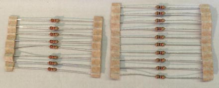
Figure 7-18. Resistors
When a resistor is used to pull up voltage (by attaching one end to positive voltage) or pull down voltage (by attaching one end to ground) (resistors are bidirectional), it eliminates the possibility of the voltage floating in an indeterminate state. Thus, a pull-up resistor ensures that the stable state is positive voltage, and a pull-down resistor ensures that the stable state is zero voltage (ground).
Switch
A switch is designed to control the flow of current between two or more pins. Switches come in all manner of shapes, sizes, and packaging. Some are designed as a simple on/off while others can be used to change current from one set of pins to another. Like buttons, switches come in a variety of mounting options from PCB (also called through hole) to panel mount for mounting in enclosures. Figure 7-19 shows a variety of switches.
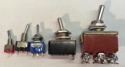
Figure 7-19. Various switches
Switches that have only one pole (leg or side) are called single-pole switches. Switches that can divert current from one set of poles to another set are called two-pole switches. Switches where there is only one secondary connection per pole are called single-throw switches. Switches that disconnect from one set of poles and connect to another while maintaining a common input are called double-throw switches. These are often combined and form the switch type (or kind) as follows.
SPST: single pole, single throw
DPST: double pole, single throw
SPDT: single pole, double throw
DPDT: double pole, double throw
3PDT: three pole, double throw
There may be other variants that you could encounter. I like to keep it straight like this; if I have just and on/off situation, I want a single throw switch. How many poles depends on how many wires or circuits I want to turn on or off at the same time. For double-throw switches, I use these when I have an “A” condition and "B” condition that I want A on when B is off and vice versa. I sometimes use multiple throw switches when I want an “A,” “B,” and off situations where I use the center position (throw) as off. You can be very creative with switches!
Transistor
A transistor (a bipolar transistor ) is designed to switch current on/off in a cycle or amplify fluctuations in current. Interestingly, transistors used to amplify current replaced vacuum tubes. If you are an audiophile, you likely know a great deal about vacuum tubes. When a resistor operates in switching mode, it behaves like a relay but its “off” position still allows a small amount of current to flow. Transistors are used in audio equipment, signal processing, and switching power supplies. Figure 7-20 shows two varieties of transistors.

Figure 7-20. Transistors
Transistors come in all manner of varieties, packaging, and ratings that make it suitable for one solution or another.
Voltage Regulator
A voltage regulator (linear voltage regulator) is designed to keep the flow of current constant. Voltage regulators often appear in electronics when we need to condition or lower current from a source. For example, we want to supply 5V to a circuit but only have a 9V power supply. Voltage regulators accomplish this (roughly) by taking current in and dissipating the excess current through a heat sink. Thus, voltage regulators have three legs: positive current in, negative, and positive current out. They are typically shaped like those shown in Figure 7-21 but other varieties exist.
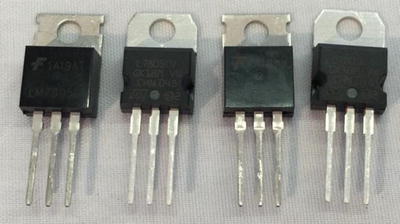
Figure 7-21. Voltage regulators
The small hole in the plate that extends out of the voltage regulator is where the heat sink is mounted. Voltage regulators are often numbered to match their rating. For example, a LM7805 produces 5V whereas a LM7833 produces 3.3V.
An example of using a voltage regulator to supply power to a 3.3V circuit on a breadboard is shown in Figure 7-22. This circuit was designed with capacitors to help smooth or condition the power. Notice the capacitors are rated with uF, which means microfarad.
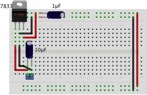
Figure 7-22. Power supply circuit on a breadboard with voltage regulator
Breakout Boards and Circuits
Breakout boards are our modular building blocks for IOT solutions. They typically combine several components together to form a function such as measuring temperature, enabling reading GPS data, communicating via cellular services, and more. Figure 7-23 shows two breakout boards. On the left is an Adafruit analog to digital converter (adafruit.com/products/1083), and on the right is an Adafruit Barometric Pressure Sensor breakout board ( https://www.adafruit.com/product/1603 ).

Figure 7-23. Breakout boards
Whenever you design a circuit or IOT solution, you should consider using breakout boards as much as possible because they simplify the use of the components. Take the Barometric Pressure Sensor, for example. Adafruit has designed this board so that all we need to do to use it is attach power and connect it to our IOT Device on its I2C bus. An I2C bus is a fast digital protocol that uses two wires (plus power and ground) to read data from circuits (or devices).
Thus, there is no need to worry about how to connect the sensor to other components to use it - just connect it up like any I2C device and start reading data! We will use several breakout boards in the projects later in this book.
Using a Breadboard to Build Circuits
If you have been following along with the projects thus far in the book, you have already encountered a breadboard to make a very simple circuit. Recall from Chapter 3 that a breadboard is a tool we use to plug components into to form circuits. Technically, we’re using a solderless breadboard. A solder breadboard has the same layout only it has only through-hole solder points on a PCB.
A breadboard allows us to create prototypes for our circuits or simply temporary circuits without having to spend the time (and cost) to make the printed circuit board. Prototyping is the process of experimenting with a circuit by building and testing your ideas. In fact, once we’ve got our circuit to work correctly, we can use the breadboard layout to help us design a PCB. Figure 7-24 shows several breadboards.
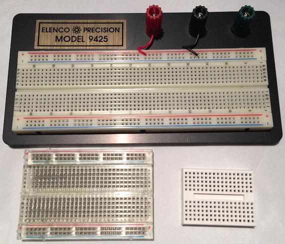
Figure 7-24. Assorted breadboards
Recall that most breadboards (there are several varieties) have a center groove (called a ravine) or a printed line down the center of the board. This signifies the terminal strips that run perpendicular to the channel are not connected. That is, the terminal strip on one side is not connected to the other side. This allows us to plug integrated circuits (IC) or chips that are packaged as two rows of pins. Thus, we can plug the IC into the breadboard with one set of pins on each side of the breadboard. We see this in the example below.
Most breadboards also have one or more sets of power rails that are connected together parallel to the ravine. If there are two sets, the sets are not connected together. The power rails may have a colored reference line but this is only for reference; you can make either one positive with the other negative. Finally, some breadboards number the terminal strip rows. These are for reference only and have no other meaning. However, they can be handy for making notes in your engineering notebook. Figure 7-25 shows the nomenclature of a breadboard and how the terminal strips and power rails are connected together.
Note
The sets of power rails are not connected together. If you want to have power on both sides of the breadboard, you must use jumpers to connect them.
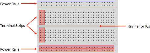
Figure 7-25. Breadboard layout
It is sometimes desirable to test a circuit out separately from code. For example, if we want to make sure all our devices are connected together properly, we can use a breadboard power supply to power the circuit. This way, if something goes horribly wrong, we don’t risk damaging our IOT device. Most breadboard power supplies are built on a small PCB with a barrel jack for a wall wart power supply, two sets of pins to plug into the power rails on the breadboard, an off switch (very handy), and some can generate different voltages. Figure 7-26 shows one of my favorite breadboard power supplies from Sparkfun (sparkfun.com/products/13157).
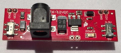
Figure 7-26. Breadboard power supply
Should our circuits require more room than what is available on a single breadboard, you can use multiple breadboards by simply jumping the power rails and continuing the circuit. To facilitate this, some breadboards can be connected using small nubs and slots on the side. Finally, most breadboards also come with an adhesive backing that you can use to mount on a plate or inside an enclosure or similar workspace. If you decide to use the adhesive backing, be forewarned that they cannot be unstuck easily - they stay put quite nicely.
Now that we know more about how breadboards work, let’s discuss the component our IOT solutions we will employ to collect data: sensors.
What Are Sensors ?
A sensor is a device that measures phenomena of the physical world. These phenomena can be things you see, like light, gases, water vapor, and so on. They can also be things you feel, like temperature, electricity, water, wind, and so on. Humans have senses that act like sensors, allowing us to experience the world around us. However, there are some things your sensors can’t see or feel, such as radiation, radio waves, voltage, and amperage. Upon measuring these phenomena, it’s the sensor’s job to convey a measurement in the form of either a voltage representation or a number.
There are many forms of sensors. They’re typically low-cost devices designed for a single purpose and with a limited capability for processing. Most simple sensors are discrete components; even those that have more sophisticated parts can be treated as separate components. Sensors are either analog or digital and are typically designed to measure only one thing. But an increasing number of sensor modules are designed to measure a set of related phenomena, such as the USB Weather Board from SparkFun Electronics ( www.sparkfun.com/products/10586 ).
The following sections examine how sensors measure data, how to store that data, and examples of some common sensors.
How Sensors Measure
Sensors are electronic devices that generate a voltage based on the unique properties of their chemical and mechanical construction. One of the common misconceptions some have about sensors is they do not manipulate the phenomena (change the event or data) they’re designed to measure. Rather, sensors sample some physical variable and turn it into a proportional electric signal (voltage, current, digital, and so on).
For example, a humidity sensor measures the concentration of water (moisture) in the air. Humidity sensors react to these phenomena and generate a voltage that the microcontroller or similar device can then read and use to calculate a value on a scale. A basic, low-cost humidity sensor is the DHT-22 available from most electronic stores ( https://www.adafruit.com/product/385 ). Figure 7-27 shows a typical DHT-22 sensor.
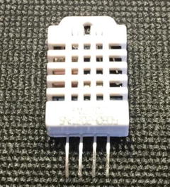
Figure 7-27. DHT-22 Humidity Sensor
The DHT-22 is designed to measure temperature as well as humidity. It generates a digital signal on the output (data pin). Although simple to use, it’s a bit slow and should be used to track data at a reasonably slow rate (no more frequently than about once every 3 or 4 seconds).
When this sensor generates data, that data is transmitted as a series of high (interpreted as a 1) and low (interpreted as a 0) voltages that the microcontroller can read and use to form a value. In this case, the microcontroller reads a value 40 bits in length (40 pulses of high or low voltage) — that is, 5 bytes — from the sensor and places it in a program variable. The first two bytes are the value for humidity, the second two are for temperature, and the fifth byte is the checksum value to ensure an accurate read. Fortunately, all this hard work is done for you in the form of a special library designed for the DHT-22 and similar sensors.
The DHT-22 produces a digital value. Not all sensors do this; some generate a voltage range instead. These are called analog sensors. Let’s take a moment to understand the differences. This will become essential information as you plan and build your sensor nodes.
Analog Sensors
Analog sensors are devices that generate a voltage range, typically between 0 and 5 volts. An analog-to-digital circuit is needed to convert the voltage to a number. But it isn’t that simple (is it ever?). Analog sensors work like resistors and, when connected to GPIO pins, often require another resistor to “pull up” or “pull down” the voltage to avoid spurious changes in voltage known as floating. This is because voltage flowing through resistors is continuous in both time and amplitude.
Thus, even when the sensor isn’t generating a value or measurement, there is still a flow of voltage through the sensor that can cause spurious readings. Your projects require a clear distinction between OFF (zero voltage) or ON (positive voltage). Pull-up and pull-down resistors ensure that you have one of these two states. It’s the responsibility of the A/D converter to take the voltage read from the sensor and convert it to a value that can be interpreted as data.
When sampled (when a value is read from a sensor), the voltage read must be interpreted as a value in the range specified for the given sensor. Remember that a value of, say, 2 volts from one analog sensor may not mean the same thing as 2 volts from another analog sensor. Each sensor’s data sheet shows you how to interpret these values.
As you can see, working with analog sensors is a lot more complicated than using the DHT-22 digital sensor. With a little practice, you will find that most analog sensors aren’t difficult to use once you understand how to attach them to a microcontroller and how to interpret their voltage on the scale in which the sensor is calibrated to work.
Digital Sensors
Digital sensors like the DHT-22 are designed to produce a string of bits using serial transmission (one bit at a time). However, some digital sensors produce data via parallel transmission (one or more bytes6 at a time). As described previously, the bits are represented as voltage, where high voltage (say, 5 volts) or ON is 1 and low voltage (0 or even -5 volts) or OFF is 0. These sequences of ON and OFF values are called discrete values because the sensor is producing one or the other in pulses — it’s either ON or OFF.
Digital sensors can be sampled more frequently than analog signals because they generate the data more quickly and because no additional circuitry is needed to read the values (such as A/D converters and logic or software to convert the values to a scale). Thus, digital sensors are generally more accurate and reliable than analog sensors. But the accuracy of a digital sensor is directly proportional to the number of bits it uses for sampling data.
The most common form of digital sensor is the pushbutton or switch. What, a button is a sensor? Why, yes, it’s a sensor. Consider for a moment the sensor attached to a window in a home security system. It’s a simple switch that is closed when the window is closed and open when the window is open. When the switch is wired into a circuit, the flow of current is constant and unbroken (measuring positive volts using a pull-up resistor) when the window is closed and the switch is closed, but the current is broken (measuring zero volts) when the window and switch is open. This is the most basic of ON and OFF sensors.
Most digital sensors are small circuits of several components designed to generate digital data. Unlike analog sensors, reading their data is easy because the values can be used directly without conversion (except to other scales or units of measure). Some may suggest this is more difficult than using analog sensors, but that depends on your point of view. An electronics enthusiast would see working with analog sensors as easier, whereas a programmer would think digital sensors are simpler to use.
Now let’s look at some of the sensors available and the types of phenomena they measure.
Examples of Sensors
An IOT solution that observes something may use at least one sensor and a means to read and interpret the data. You may be thinking of all manner of useful things you can measure in your home or office, or even in your yard or surroundings. You may want to measure the temperature changes in your new sunroom, detect when the mail carrier has tossed the latest circular in your mailbox, or perhaps keep a log of how many times your dog uses his doggy door. I hope that by now you can see these are just the tip of the iceberg when it comes to imagining what you can measure.
What types of sensors are available? The following sections describe some of the more popular sensors and what they measure. I also provide a few hints on how you might want to use the sensor in an IOT project. However, this is just a sampling of the growing array of sensors available. Perusing the catalogs of online electronics vendors like Mouser Electronics ( www.mouser.com ), SparkFun Electronics ( www.sparkfun.com ), and Adafruit Industries ( www.adafruit.com ) will reveal many more examples.
I also include photos of popular examples for some of the sensor types.
Accelerometers
These sensors measure motion or movement of the sensor or whatever it’s attached to. They’re designed to sense motion (velocity, inclination, vibration, and so on) on several axes. Some include gyroscopic features. Most are digital sensors. A Wii Nunchuck (or WiiChuck) contains a sophisticated accelerometer for tracking movement. Aha: now you know the secret of those funny little thingamabobs that came with your Wii! You may want to add accelerometers if your IOT project involves something in motion and the observation of that motion provides useful information.
Audio Sensors
Perhaps this is obvious, but microphones are used to measure sound. Most are analog, but some of the better security and surveillance sensors have digital variants for higher compression of transmitted data. IOT projects such as home security, child monitoring, ghost hunting, or auditory health can all benefit from integrating audio sensors.
Barcode Readers
These sensors are designed to read barcodes. Most often, barcode readers generate digital data representing the numeric equivalent of a barcode. Such sensors are often used in inventory-tracking systems to track equipment through a plant or during transport. They’re plentiful, and many are economically priced, enabling you to incorporate them into your own projects. If your IOT project requires capturing data from an object, you may want to consider barcodes.
For example, if you want to sense when parking lot subscribers enter or exit an unattended parking lot, you could position a barcode reader at the gates that read barcodes that you design and distribute to your subscribers. When the car pulls up to the gate, the barcode reader can read the barcode, log the entry, and raise the gate. If you’ve ever lived in a large city, worked in a controlled office complex, or were a commuter student, you may have encountered parking solutions like this.
Biometric Sensors
A sensor that reads fingerprints, irises, or palm prints contains a special sensor designed to recognize patterns. Given the uniqueness inherit in patterns such as fingerprints and palm prints, they make excellent components for a secure access system. Most biometric sensors produce a block of digital data that represents the fingerprint or palm print. IOT projects that require a greater level of security may want to include a biometric sensor to help identify the user of the system.
Capacitive Sensors
A special application of capacitive sensors, pulse sensors are designed to measure your pulse rate and typically use a fingertip for the sensing site. Special devices known as pulse oximeters (called pulse-ox by some medical professionals) measure pulse rate with a capacitive sensor and determine the oxygen content of blood with a light sensor.
If you own modern electronic devices, you may have encountered touch-sensitive buttons that use special capacitive sensors to detect touch and pressure. If your IOT project needs to measure any sort of movement, or respond to touch, capacitive sensors can help provide a futuristic non-tactile interface. The Touch Bar on the latest MacBook Pro is an example of such a solution.
Figure 7-28 shows two examples of touch-sensitive modules that you can buy from Adafruit. In this case, we see breakout boards for a momentary switch ( www.adafruit.com/products/1374 ) and a toggle switch ( www.adafruit.com/products/1375 ).

Figure 7-28. Touch Capacitive Sensor Breakout Boards
Coin Sensors
This is one of the most unusual types of sensors. These devices7 are like the coin slots on a typical vending machine. Like their commercial equivalent, they can be calibrated to sense when a certain size of coin is inserted. Although not as sophisticated as commercial units that can distinguish fake coins from real ones, coin sensors can be used to add a new dimension to your projects. A great, practical IOT project for parents would be a coin-operated WiFi station where the children have to buy their own Internet time. Not only will this keep them from using the Internet too much, it may also help teach them how to budget their allowance. Now, that should keep the kids from spending too much time on the Internet!
Current Sensors
These are designed to measure voltage and amperage. Some are designed to measure change, whereas others measure load. IOT projects that integrate circuits or need to monitor the flow of electricity will need a current sensor. These may be some of the more esoteric projects, but you can use these sensors to monitor the behavior of existing solutions without modifying them.
For example, if you wanted to adapt sensors to observe a manufacturing machine, you could add sensors that monitor the current to the various components. That is, you may be able to record when voltage is applied to motors, actuators, or even warning lights to determine when (or how much) the devices are activated. However, as a hobbyist, you are more likely interested in building your own multimeter or similar tool.
Flex/Force Sensors
Resistance sensors measure flexes in a piece of material or the force or impact of pressure on the sensor. Flex sensors may be useful for measuring torsional effects or to measure finger movements (like in a Nintendo Power Glove). Flex-sensor resistance increases when the sensor is flexed. For example, if you want to create an IOT solution that reports your fishing experience in real time, you might want to use a flex sensor on your fishing rod to report every time you cast or got a hit on your lure.
Gas Sensors
There are a great many types of gas sensors. Some measure potentially harmful gases such as LPG and methane and other gases such as hydrogen, oxygen, and so on. Other gas sensors are combined with light sensors to sense smoke or pollutants in the air. The next time you hear that telltale and often annoying low-battery warning beep8 from your smoke detector, think about what that device contains. Why, it’s a sensor node! If your IOT project needs to observe or detect any form of gas, especially if it involves reacting to certain gases or levels thereof, you will need to use the appropriate gas sensors.
Light Sensors
Sensors that measure the intensity or lack of light are special types of resistors: light-dependent resistors (LDRs), sometimes called photo resistors or photocells. Thus, they’re analog by nature.
If you own a Mac laptop, chances are you’ve seen a photo resistor in action when your illuminated keyboard turns itself on in low light. Special forms of light sensors can detect other light spectrums such as infrared (as in older TV remotes). For example, if you want your IOT project to automatically adjust the brightness of its display, a light sensor is the component you need.
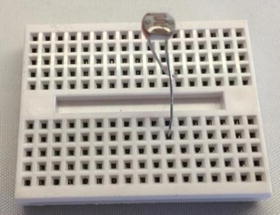
Figure 7-29. Mini Photocell
The following show two examples of light sensors. Figure 7-29 shows a typical mini photocell ( www.sparkfun.com/products/9088 ) and Figure 7-30 shows a color sensor ( www.adafruit.com/products/1334 ).
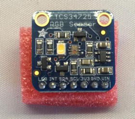
Figure 7-30. Color Sensor Breakout Board
Liquid-Flow Sensors
These sensors resemble valves and are placed inline in plumbing systems. They measure the flow of liquid as it passes through. Basic flow sensors use a spinning wheel and a magnet to generate a Hall effect (rapid ON/OFF sequences whose frequency equates to how much water has passed). If your IOT project involves any form of liquid such as a garden pond or irrigation system, knowing the flow of the water may be helpful in learning or observing something.
Liquid-Level Sensors
A special resistive solid-state device can be used to measure the relative height of a body of water. One example generates low resistance when the water level is high and higher resistance when the level is low. Like liquid-flow sensors, liquid-level sensors are typically used in the same solution. Figure 7-31 shows a typical liquid-level sensor that operates as a switch where the float closes the switch when the water level rises.

Figure 7-31. Water-Level Sensor
Location Sensors
Modern smartphones have GPS sensors for sensing location, and of course GPS devices use the GPS technology to help you navigate. Fortunately, GPS sensors are available in low-cost forms, enabling you to add location sensing to your project. GPS sensors generate digital data in the form of longitude and latitude, and most can also sense altitude. If your IOT project needs to report its location, a GPS sensor can give you very accurate readings. However, like most sensors, GPS sensors can have a degree of inaccuracy. Depending on how close you need to locate something, you may need to spend a bit more on a more accurate GPS sensor.
Magnetic-Stripe Readers
These sensors read data from magnetic stripes (like that on a credit card) and return the digital form of the alphanumeric data (the actual strings). IOT projects that include a security component may want to use a magnetic-stripe reader to help identify a user. When combined with a password and a biometric sensor, security can be increased considerably. That is, someone would have to know something (a password or pin), possess something (security card with a magnetic-stripe encoded with a key phrase, number, user id, etc.), and be validated as someone (fingerprint) before gaining access.
Magnetometers
These sensors measure orientation via the strength of magnetic fields. A compass is a sensor for finding magnetic north. Some magnetometers offer multiple axes to allow even finer detection of magnetic fields. This is another sensor that you may not encounter very often, but if your IOT project needs to measure magnetic fields from motors or atmospheric phenomena, you may want to look at magnetometers.
Moisture Sensors
Moisture sensors measure the amount of moisture in a substance (such as soil) or in the air. They typically send data in the form of a voltage reading where low values indicate less moisture. You often find moisture sensors in atmospheric projects or even plant monitoring solutions. Figure 7-32 shows a typical soil moisture sensor (). Notice the prongs are the portion of the sensor inserted into the soil.
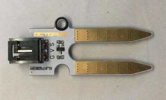
Figure 7-32. Soil Moisture Sensor
Proximity Sensors
Often thought of as distance sensors, proximity sensors use infrared or sound waves to detect distance, movement, or the range to/from an object. Made popular by low-cost robotics kits, the Parallax Ultrasonic Sensor uses sound waves to measure distance by sensing the amount of time between pulse sent and pulse received (the echo). For approximate distance measuring,9 it’s a simple math problem to convert the time to distance. If you’re building an IOT project that detects movement or proximity such as a motion sensing camera, you may want to use proximity sensors.
The following figures show two types of proximity sensors. Figure 7-33 shows a popular passive infrared sensor (PIR) motion sensor ( www.sparkfun.com/products/13285 ).
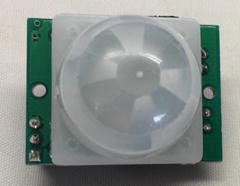
Figure 7-33. PIR Motion Sensor
Figure 7-34 shows an ultrasonic sensor ( www.sparkfun.com/products/13959 ) used in many projects from robots to drones.
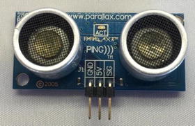
Figure 7-34. Ultrasonic Proximity Sensor
Radiation Sensors
Among the more serious sensors are those that detect radiation. This can also be electromagnetic radiation (there are sensors for that too), but a Geiger counter uses radiation sensors to detect harmful ionizing. In fact, it’s possible to build your very own Geiger counter using a sensor and an Arduino (and a few electronic components). This is one sensor that you may not encounter as a hobbyist. However, there are several kits for building your own Geiger counter such as those from Adafruit ( www.adafruit.com/products/483 ).
RFID Sensors
Radio frequency identification uses a passive device (sometimes called an RFID tag) to communicate data using radio frequencies through electromagnetic induction. For example, an RFID tag can be a credit-card-sized plastic card, a label, or something similar that contains a special antenna, typically in the form of a coil, thin wire, or foil layer that is tuned to a specific frequency.
When the tag is placed near the reader, the reader emits a radio signal; the tag can use the electromagnet energy to transmit a nonvolatile message embedded in the antenna, in the form of radio signals which is then converted to an alphanumeric string.10 RFID sensors are another good choice for security systems. If you have pets, you may want to visit your veterinarian to inquire about RFID sensors that act as hidden owner identification tags. If you know the frequency, you can even use it to help detect when your pet goes through a pet door. Figure 7-35 shows an RFID reader (sensor) that you can use to read RFID tags via USB ( www.sparkfun.com/products/9963 ).
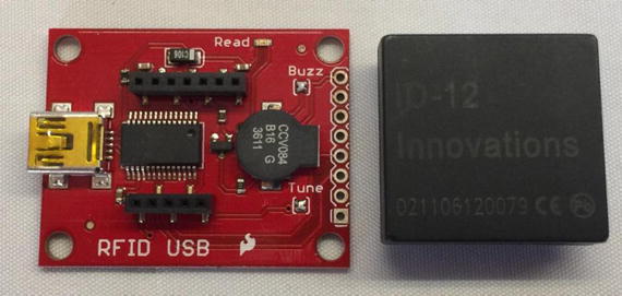
Figure 7-35. RFID Reader
Speed Sensors
Like flow sensors, simple speed sensors like those found on many bicycles use a magnet and a reed switch to generate a Hall effect. The frequency combined with the circumference of the wheel can be used to calculate speed and, over time, distance traveled. If your IOT solution needs to read movement, you can use a magnetic switch and a magnet to detect rotation. For example, bicycle speedometers often use a magnet and magnetic switch to detect the number of rotations, circumference of the wheel, and frequency of the actions to calculate speed.
Switches and Pushbuttons
These are the most basic of digital sensors used to detect if something is set (ON) or reset (OFF). Even so, you can use switches and buttons to build a user interface, for controlling other devices, or even turning the thing on!
Tilt Switches
These sensors can detect when a device is tilted one way or another. Although very simple, they can be useful for low-cost motion-detection sensors. They are digital and are essentially switches. If your IOT solution needs to detect when the device is leaning, you can use tilt sensors to trigger at a certain lean angle. For example, some modern motorcycles use tilt sensors to turn on cornering lights – headlamps angled to improve vision around a turn at night.
Touch Sensors
The touch-sensitive membranes formed into keypads, keyboards, pointing devices, and the like are an interesting form of sensor. You can use touch-sensitive devices like these for collecting data from humans. Touch sensors can help you build a user interface for your IOT project that can be presented in a low-profile form or to save space in a console, project box, etc.
Video Sensors
As mentioned previously, it’s possible to obtain very small video sensors that use cameras and circuitry to capture images and transmit them as digital data. If you want to incorporate a video element to your IOT project such as a security solution, you can add a camera or video sensor to capture a visual component that can help provide information beyond the incident measurements. That is, you can review a photo and learn more than simply something moved or approached the device. For example, you can build an IOT project that detects movement and takes a photo if something gets close enough or, perhaps, moves faster than a certain threshold.11
Weather Sensors
Sensors for temperature, barometric pressure, rain fall, humidity, wind speed, and so on are all classified as weather sensors. Most generate digital data and can be combined to create comprehensive environmental solutions. Figure 7-36 shows a common breakout board for the BMP280 pressure and temperature sensor ( www.adafruit.com/products/2651 ).
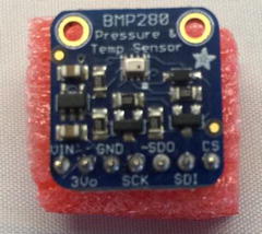
Figure 7-36. BMP280 Pressure and Temperature Sensor
With this and other easy-to-use sensors, it’s possible to build your own weather station from about a dozen inexpensive sensors, your MicroPython board, and a bit of programming to interpret and combine the data. In fact, we’ll do that in Chapter 10!
Tip – If you want to see more sensors, you can purchase any number of sensors from Adafruit ( www.adafruit.com/category/35 ) or Sparkfun ( www.sparkfun.com/categories/23 ).
Summary
Learning how to work with electronics as a hobby or to create an IOT solution does not require a lifetime of study or a change of vocation. Indeed, learning how to work with electronics is all part of the fun of experimenting with the IOT! I have met many people who have learned electronics on their own and while most will admit formal study is essential for mastering the topic, you can learn quite a lot on your own - enough to become proficient working with the basic electronic components typically found in IOT projects.
This chapter presented the basics of electronics components including the use of breadboards, common components, and example circuits. This and a bit of key knowledge of how to use a multimeter will get you a long way toward becoming proficient with electronics. We also learned about one of the key components of an IOT solution – sensors. We discovered two ways they communicate (digital and analog) and a bit of what types of sensors are available.
In the next chapter, we will dive into our first electronics project – the equivalent of a “hello, world!” project for hardware. We’ll see how to connect our MicroPython board to a few components and write a Python program to control them. Cool!
Footnotes
1 However, there is no substitute for formal training! If you want to explore electronics beyond the tutorial in this chapter, you may want to consider formal training or even a self-paced course as described in the sidebar, “I Want to Learn More!”
2 Older multimeters have an analog gauge. You can still find them if you want a bit of old school feel.
3 Yes, a bit of OCD there. Check, double-check, check again.
5 A variant of Ohm’s law ( https://en.wikipedia.org/wiki/Ohm's_law ).
6 This depends on the width of the parallel buffer. An 8-bit buffer can communicate 1 byte at a time, a 16-bit buffer can communicate 2 bytes at a time, and so on.
8 I subscribe to the more is better theory and have many detectors in our home, which is great but when the batteries run down, I can never tell which detector is beeping! This becomes maddeningly frustrating when they beep only once or twice then go silent. Fortunately, I’ve replaced nearly all of them with the newest 10-year battery variants. No more wild beep goose chases!
9 Accuracy may depend on environmental variables such as elevation, temperature, and so on.
11 Have you ever thought it would be great if you could catch a photo of whatever critter is eating your garden? Build your own critter camera with a proximity sensors and an infrared camera!