Chapter 4
Azure Load Balancer
Overview
Azure provides a load balancer service that enables you to build scalable application architectures with multiple application or web servers where client traffic is distributed based on different algorithms suitable for your environment. The Azure Load Balancer service works on layer 4 of the OSI model to provide secure load balancing for internal applications from the public internet and internal networks.
You can deploy two types of load balancers in Azure (see Figure 4-1):
Public load balancer A public load balancer helps you securely publish internal applications or web servers or services to internet-based clients without exposing the back-end service or virtual machine (VM) directly. Clients connect to the public load balancer and, based on the load-balancing algorithm defined on the load balancer, traffic is routed to the appropriate back-end service.
Internal load balancer An internal load balancer helps you provide secure access to internal applications, web servers, or services to internal-only clients. The clients can be connected directly to the virtual network (vNET) in Azure or via hybrid-connectivity solutions such as a site-to-site (S2S) VPN, point-to-site (P2S) VPN, or ExpressRoute. Direct public access to the load balancer is not possible.

FIGURE 4-1 Public and internal load balancers.
Azure Load Balancer features
Following are some key concepts and benefits of using the Azure Load Balancer service:
Support for both public and internal load-balancing options Azure Load Balancer supports both public and internal-only load-balancing options, which enables it to address various application scenarios that may or may not require public exposure.
Highly scalable Azure Load Balancer is highly scalable. The service scales up automatically as connection requests to back-end services increase.
Support for availability zones The standard Azure Load Balancer supports the use of availability zones to enhance the service’s resiliency and availability.
Secure access by default The standard Azure Load Balancer is designed to block all incoming traffic by default unless traffic is explicitly allowed through the use of network security groups (NSGs). The basic Azure Load Balancer, on the other hand, is open to public networks by default and requires configuration to block incoming traffic.
Outbound traffic management You can use Azure Load Balancer to manage egress of all outbound traffic from VMs and to better control that traffic.
Support for multiple load-balancing algorithms There are multiple load-balancing algorithms available to define the most appropriate routing method for your application. You can switch from one load-balancing algorithm to another as the needs of your application evolve.
Support for IPv6 Azure Load Balancer supports IPv6 connectivity availability. So, you can set up Azure Load Balancer to accommodate applications that require IPv6 for client connectivity.
Support for multiple ports and IP addresses Azure Load Balancer supports the use of multiple IP addresses and ports to load-balance traffic for multiple application back ends.
Support for TCP and UDP flows Azure Load Balancer supports both TCP and UDP traffic load balancing.
Design concepts and deployment considerations
It is important to understand the different components that comprise Azure Load Balancer to appropriately design and deploy it for your various application requirements. The following sections review each of these components in more detail.
Front-end IP address
As mentioned, Azure Load Balancer works with both public and internal-only access. To support these scenarios, you can set up the load balancer with either a public IP address or a private IP address. The IP address you assign dictates whether the load balancer is a public or an internal load balancer, as this is the ingress point for your clients to connect to the application or service.
Back-end pool
The back-end pool refers to the VM scale set (VMSS) or VMs that are hosting the web service or application that you want to route traffic. As you add more instances of VMs to the back-end pool, the load balancer automatically incorporates those into its algorithm and routes traffic to the new instances based on routing logic defined in the rules.
In the case of a VMSS, this routing recalculation is automatic, as the VMSS adds or removes instances dynamically. With VMs, the recalculation occurs when you add or remove a VM from the back-end pool.
Health probes
Health probes define parameters that Azure Load Balancer must use to determine the health status of instances in the back-end pool. Depending on the type of load balancer provisioned, the types of health probes supported are as follows:
Standard load balancer TCP, HTTP, and HTTPS
Basic load balancer TCP and HTTP
Health probe parameters include the frequency, expected responses, and thresholds to help the load balancer determine when a back-end instance is unhealthy. In such cases, the load balancer stops routing new traffic to the unhealthy instance until subsequent health probes confirm that the instance is once again in a healthy state.
Be aware that with a standard load balancer, any connections that already exist will continue to be routed to the unhealthy instance until the flow is disconnected, terminated, or times out. With a basic load balancer, however, when the instance is deemed unhealthy, TCP flows are disconnected regardless of the connection state.
Load-balancing rules
Load-balancing rules dictate how ingress traffic is managed based on the source IP, source port, destination IP, destination port, and IP protocol details in the connection flow. The rule connects a front-end IP address, public or private, and a port to multiple back-end IP addresses and ports. (See Figure 4-2.) The load-balancing algorithm selected is used thereafter to route the traffic to the back-end pool. Be aware that all load-balancer front-end and back-end endpoints must reside in the same Azure vNET. vNET spanning is not supported.
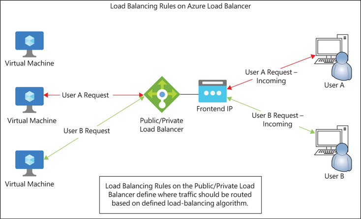
FIGURE 4-2 Public and internal load-balancer rules.
High-availability (HA) ports load-balancing rule
The high-availability (HA) ports load-balancing rule instructs the Azure service that all traffic for all protocols on all ports must be routed in a load-balanced manner, regardless of the port number. This rule is configured when the protocol is set to all, and front-end and back-end ports are set to 0. With this rule, load-balancing decisions are still made per flow based on the five-tuple connection logic that includes the source IP address, source port, destination IP address, destination port, and protocol. (See Figure 4-3.)

FIGURE 4-3 Azure internal load balancer with HA rules.
Inbound network address translation (NAT) rules
You can set up inbound network address translation (NAT) rules to forward incoming traffic to a specific back-end VM based on the combination of the front-end IP address and the port. (See Figure 4-4.) Traffic can be routed to one or more VMs in a VMSS as part of a NAT pool setup.

FIGURE 4-4 Inbound NAT rules.
Outbound source network address translation (SNAT) rules
You can set up a standard public load balancer with outbound source network address translation (SNAT) rules for all back-end VM or VMSS resources for any internet-bound egress traffic as well as traffic to other endpoints. (See Figure 4-5.) This helps present the public IP of the load balancer to any external endpoint without exposing IP address information associated with the back-end instance itself.

FIGURE 4-5 Outbound SNAT rules.
You can set up a public IP prefix to provide the load balancer with a public IP pool. This can then be used to scale the number of outbound connections across all IPs and ports. You can also map back-end resources to individual public IP addresses or set them up to use any IP address in the pool to prevent port exhaustion. This improves redundancy and scalability.
Load-balancing algorithms
There are two load-balancing algorithms to route incoming traffic to back-end resources. Each algorithm provides a different level of redundancy and session persistence. The algorithm you select will depend on your use case. The two load-balancing algorithms are as follows:
Hash-based This algorithm generates a unique hash based on a combination of the source IP, source port, destination IP, destination port, and protocol type. Any connection from the same source IP using a different source port to the same application back end will result in a new hash, which might route traffic to a different back-end endpoint each time. This type of routing is useful in scenarios where the application does not require stickiness for all sessions originating from a particular client. It can also help improve responsiveness, as a larger number of sessions from a smaller number of source clients will be evenly distributed across a back-end pool.
Source IP affinity With this algorithm, traffic from the same source IP to the same destination IP, using the same protocol type, is routed to the same endpoint each time. This helps ensure that a back-end endpoint that is already managing active client sessions responds to any additional incoming client sessions with the same source IP, destination IP, and protocol. You can set up the source IP affinity algorithm to check the source IP and destination IP of incoming requests, or to check the source IP, destination IP, and protocol type, before determining which back-end instance the connection should be routed to.
Availability zones
The standard Azure Load Balancer supports the use of availability zones to increase redundancy and availability in the event of a zone failure. You can set up availability zones to route traffic across zones, and to failover to a different active zone if a zone you are using goes offline.
You can set up Azure Load Balancer to use availability zones for redundancy in three ways:
Zone redundant If the Azure region on which Azure Load Balancer is deployed supports availability zones, you can set the front-end IP address as zone redundant. That way, if there is a failure within a zone, the IP address will survive it, and will route new incoming requests to the back-end pool. (Of course, this assumes there are resources in the back-end pool that are set up in a similar zone-redundant manner and are online in case of a zone failure.) It is recommended that you use a zone-redundant Azure Load Balancer for your production workloads.
Zonal With zonal redundancy, the load balancer is redundant within a single zone. If that zone experiences a failure, the load balancer does not failover to another zone. It remains offline for the duration of the zone’s outage. You might use zonal redundancy in scenarios in which different IP addresses are set up in different zones within a region to expose an application and use a traffic-management service like Azure Traffic Manager. In this case, traffic is routed across all zones, depending on their availability. This enables you to monitor the health and availability of each zone independently, as each front end in a zone has its own unique public IP.
Non-zonal Here, the load balancer is set up in a “no-zone” front-end configuration with zero redundancy. This is not a recommended configuration for production workloads.
Azure Load Balancer walkthrough
The following sections walk you through the process of creating an Azure Load Balancer using the Azure Portal, Azure PowerShell, and the Azure CLI. If you are following along, be sure to select resources and resource names based on your environment, including unique Azure Load Balancer and VM names. Also be sure to delete any unwanted resources after you have completed testing to reduce charges levied by Microsoft for these resources.
Using Azure Portal
To create a public Azure Load Balancer using the Azure Portal, follow these steps:
Log into the Azure Portal, type load balancer in the search box to locate the service, and select it from the list that appears. (See Figure 4-6.)
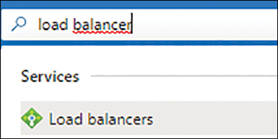
FIGURE 4-6 Creating an Azure Load Balancer in the Azure Portal.
Click Create or Create Load Balancer to start the Create Load Balancer wizard. (See Figure 4-7.)

FIGURE 4-7 Creating the load balancer.
In the Basics tab of the Create Load Balancer wizard (see Figure 4-8), enter the following information and click Next:
Subscription Select the subscription to host the Azure Load Balancer.
Resource Group Select the resource group you want to host the Azure Load Balancer. Alternatively, click the Create New link and follow the prompts to create a new resource group.
Name Type a name for the Azure Load Balancer. If the name you type is already in use, the wizard will prompt you to enter a different name.
Region Select the Azure region in which you want to host the Azure Load Balancer.
SKU Select the Standard option button.
Type Select the Public option button.
Tier Select the Regional option button.
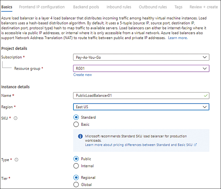
FIGURE 4-8 The Basics tab of the Create Load Balancer wizard.
In the Frontend IP Configuration tab of the Create Load Balancer wizard (see Figure 4-9), click Add a Frontend IP Configuration to create a front-end IP address.

FIGURE 4-9 The Frontend IP Configuration Tab in the Create Load Balancer wizard.
In the Add Frontend IP Address options (see Figure 4-10), enter the following information:
Name Enter a name for the front-end IP address. If the name you type is already in use, you’ll be prompted to enter a different name.
IP Version Select the IPv4 option button.
IP Type Select the IP Address option button.
Public IP Address Select an existing public IP address from the drop-down list. Alternatively, click the Create New link.

FIGURE 4-10 Add front-end IP address.
Clicking the Create New link opens the Add a Public IP Address options.
In the Add a Public IP Address options (see Figure 4-11), enter the following information and click OK:
Name Enter a name for your public IP address. If the name you type is already in use, you’ll be prompted to enter a different name.
Availability Zone Specify whether you want to set up an availability zone and, if so, which kind—in this case, Zone-Redundant.
Routing Preference Select the option button for your routing preference—in this case, Microsoft Network.

FIGURE 4-11 Adding a public IP address.
In the Add Frontend IP Address options, click OK. Then click Next in the Frontend IP Configuration tab in the Create Load Balancer wizard.
In the Backend Pools tab of the Create Load Balancer wizard (see Figure 4-12), click Add a Backend Pool.
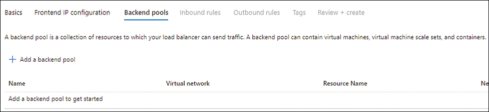
FIGURE 4-12 The Backend Pools tab of the Create Load Balancer wizard.
In the Add Backend Pool options (see Figure 4-13), enter the following information:
Name Enter a name for the back-end pool. If the name you type is already in use, you’ll be prompted to enter a different name.
Virtual Network Select the vNET on which you want to create the back-end pool.
Backend Pool Configuration Select the NIC option button.
IP Version Select the IPv4 option button.
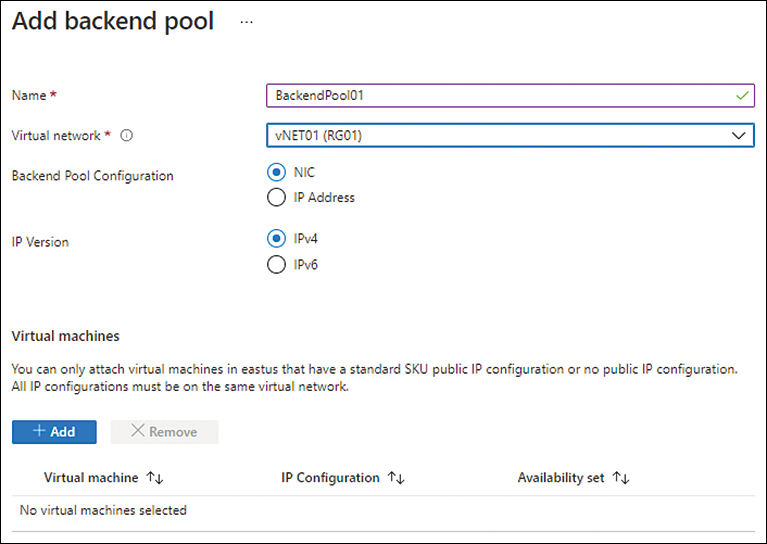
FIGURE 4-13 The Add Backend Pool settings.
Under Virtual Machines, click the Add button.
In the Add Virtual Machines to Backend Pool settings (see Figure 4-14), select the VMs you want to set up in the back-end pool.

FIGURE 4-14 Add virtual machines to the back-end pool.
Confirm that the VMs you selected are listed in the Virtual Machines section of the Add Backend Pool settings. (See Figure 4-15.) Then click Next.
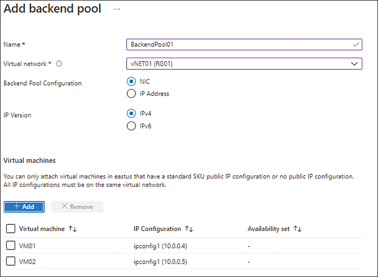
FIGURE 4-15 The Add Backend Pool settings with the selected VMs listed.
In the Inbound Rules tab of the Create Load Balancer wizard (see Figure 4-16), click Add a Load Balancing Rule.

FIGURE 4-16 Creating inbound load-balancing rules.
In the Add Load Balancing Rule settings (see Figure 4-17), enter the following information:
Name Enter a name for the load-balancing rule. If the name you type is already in use, you’ll be prompted to enter a different name.
IP Version Select the IPv4 option button.
Frontend IP Address Select the front-end IP you created earlier.
Backend Pool Select the back-end pool configuration you created earlier.
Protocol Select the appropriate protocol—in this example, TCP.
Port Enter the port to use for load-balancing—in this case, 80.
Backend Port Enter the back-end port to use for load-balancing—again, 80.
Health Probe Click the Create New link.
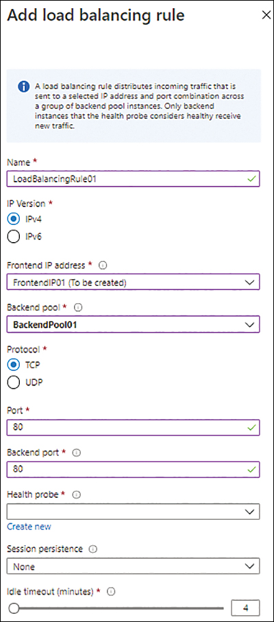
FIGURE 4-17 Add the load-balancing rule.
In the Add Health Probe settings (see Figure 4-18), enter the following information and click OK:
Name Enter a name for the health probe. If the name you type is already in use, you’ll be prompted to enter a different name.
Protocol Select the appropriate protocol—in this example, HTTP.
Port Enter the port to use for testing—here, 80.
Path Enter the path to use for testing—in this case, /.
Interval Enter the interval to use for testing—in this example, 5.
Unhealthy Threshold Enter the threshold to determine whether an instance is unhealthy—here, 2.
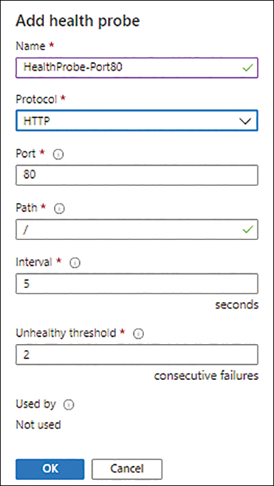
FIGURE 4-18 The Add Health Probe settings.
Back in the Add Load Balancing settings, open the Session Persistence drop-down list and select the persistence you want to use. (See Figure 4-19.)

FIGURE 4-19 Selecting a Session Persistence option in the Add Load Balancing Rule settings.
Leave the rest of the settings in the Add Load Balancing Rule options as is and click Add.
In the Outbound Rules tab of the Create Load Balancer wizard (see Figure 4-20), leave the default settings as is, and click Next.

FIGURE 4-20 The Outbound Rules tab in the Create Load Balancer wizard.
In the Tags tab of the Create Load Balancer wizard (see Figure 4-21), enter any tags required for the load balancer or leave the fields blank. Then click Next.

FIGURE 4-21 The Tags tab in the Create Load Balancer wizard.
On the Review + Create tab, review your settings, and click Create.
Azure creates the load balancer.
After Azure builds the new load balancer, click Go to Resource.
In the left pane of the load balancer’s blade, click Frontend IP Configuration.
Click the link for the front-end IP address you just created to test whether your application’s load-balancing is working as expected. (See Figure 4-22.)

FIGURE 4-22 Front-end IP configuration.
Using Azure PowerShell
You can create a load balancer using Azure PowerShell with the New-AzLoadBalancer command and various switches. The following code shows you how. Use this snippet to create the same load balancer configuration as you did in the Azure Portal. (Replace all variables and configuration as per your environment.) When you do, be sure to delete the previous load balancer or give this new load balancer a different name:
#Define variables
$Region = 'eastus'
$RG = 'RG01'
$LBName = 'PublicLoadBalancer01'
$LBPIP = 'FrontendPIP01'
$BEPool = 'BackendPool01'
#Create zone redundant Public IP
$LBpublicip = @{
    Name = '$LBPIP'
    ResourceGroupName = 'RG01'
    Location = $location
    Sku = 'Standard'
    AllocationMethod = 'static'
    Zone = 1,2,3
}
New-AzPublicIpAddress @LBpublicip
#Create public load balancer
# Place public IP into a variable
$azlbpublicIp = Get-AzPublicIpAddress -Name $LBPIP -ResourceGroupName $RG
# Create load balancer front-end configuration
$azLBfrontend = New-AzLoadBalancerFrontendIpConfig -Name $LBPIP -PublicIpAddress
$azlbpublicIp
# Create back-end address pool configuration
$azlbbepool = New-AzLoadBalancerBackendAddressPoolConfig -Name $BEPool
# Create the health probe
$healthprobe = @{
    Name = 'HealthProbe-Port80'
    Protocol = 'http'
    Port = '80'
    IntervalInSeconds = '360'
    ProbeCount = '5'
    RequestPath = '/'
}
$httphealthprobe = New-AzLoadBalancerProbeConfig @healthprobe
# Create the load-balancer rule
$azloadbalancingrule = @{
    Name = 'LBRule-HTTP-01'
    Protocol = 'tcp'
    FrontendPort = '80'
    BackendPort = '80'
    IdleTimeoutInMinutes = '15'
    FrontendIpConfiguration = $azlbfrontend
    BackendAddressPool = $azlbbepool
}
$lbhttprule = New-AzLoadBalancerRuleConfig @azloadbalancingrule -EnableTcpReset
-DisableOutboundSNAT
## Create the load balancer
$loadbalancer = @{
    ResourceGroupName = $RG
    Name = $LBName
    Location = $Region
    Sku = 'Standard'
    FrontendIpConfiguration = $frontend
    BackendAddressPool = $azlbbepool
    LoadBalancingRule = $lbhttprule
    Probe = $httphealthprobe
}
New-AzLoadBalancer @loadbalancer
## Add VM01 to the back-end pool
$lb = Get-AzLoadBalancer `
    -ResourceGroupName $RG `
    -Name $LBName
$nic1 = Get-AzNetworkInterface `
    -ResourceGroupName $RG `
    -Name "VM01*"
$nic1.IpConfigurations[0].LoadBalancerBackendAddressPools=$lb.BackendAddressPools[0]
Set-AzNetworkInterface -NetworkInterface $nic1
## Add VM02 to the back-end pool
$nic2 = Get-AzNetworkInterface `
    -ResourceGroupName $RG `
    -Name "VM02*"
$nic2.IpConfigurations[0].LoadBalancerBackendAddressPools=$lb.BackendAddressPools[1]
Set-AzNetworkInterface -NetworkInterface $nic2
Using the Azure CLI
You can create a load balancer using the Azure CLI with the az network lb create command and various switches to set its parameters. The following Bash script shows you how. Use this snippet to create the same load balancer as you did in the previous sections. (Replace all variables and configuration as per your environment.) Be sure to either delete the previous load balancer or give this new one a different name:
#Define variables
region='eastus'
rg='RG01'
publicip='FrontendPIP01'
lbname='PublicLoadBalancer01'
#Create public IP address
az network public-ip create
    --resource-group $rg
    --name $publicip
    --sku Standard
    --zone {1,2,3}
    --tier Regional
    --location $region
#Create load balancer
az network lb create
    --resource-group $rg
    --name $lbname
    --sku Standard
    --public-ip-address FrontendPIP01
    --frontend-ip-name Frontend
    --backend-pool-name BackEndPool01
    --location $region
#Create health probe
az network lb probe create
    --resource-group $rg
    --lb-name $lbname
    --name HealthProbe-Port80
    --protocol tcp
    --port 80
#Create load balancing rule
az network lb rule create
    --resource-group $rg
    --lb-name $lbname
    --name LBRule-HTTP
    --protocol tcp
    --frontend-port 80
    --backend-port 80
    --frontend-ip-name Frontend
    --backend-pool-name BackEndPool01
    --probe-name HealthProbe-Port80
    --disable-outbound-snat true
    --idle-timeout 15
## Add VM01 and VM02 network cards to the back-end pool
array=(VMNIC01 VMNIC02)
  for vmnic in "${array[@]}"
  do
    az network nic ip-config address-pool add
     --address-pool BackEndPool01
     --ip-config-name ipconfig1
     --nic-name $vmnic
     --resource-group $rg
     --lb-name $lbname
  done
Best practices
Following are some best practices recommended for Azure Load Balancer that can help you better deploy and manage the service in your environment:
Upgrade to standard It is highly recommended that you upgrade from the basic Azure Load Balancer to the standard Azure Load Balancer as soon as possible. The standard option provides a number of benefits compared to the basic option. These include the following:
99.99% SLA
Support for multiple inbound and outbound front ends
Support for availability zones
Support for health probes for the HTTPS protocol
Large number of front-end configurations
Larger back-end pool sizes
Use multiple front ends Using multiple front ends can help you scale the number of connections supported for load balancing on specific ports or IP addresses. In addition, this feature offers more benefits, such as zone redundancy, by setting up your front ends in separate zones for higher resiliency.
Integrate with Azure Firewall You can integrate Azure Load Balancer with Azure Firewall. This enables you to use Azure Firewall’s threat intelligence feature to protect web applications in the back-end pool. If your web application is used to manage critical business data, it is highly recommended that you use this feature to protect against known and evolving threats.
Setup Network Watcher Network Watcher is an Azure service that enables you to identify, analyze, and monitor any issues on the network level to or from an Azure service. It is a good practice to set up Network Watcher in the regions where load balancers are created and to set up alerts to flag anomalous activities on the network.
Use service tags in NSG rules You can use NSG rules to block inbound traffic to back-end pool resources—except inbound traffic that originates from a load balancer. Load balancers can still connect with back-end pool resources to monitor health and route traffic. However, any changes to the load balancer’s IP address can break this connectivity if the corresponding rules are not updated in the NSG. To resolve this, you can use service tags. These Microsoft-managed tags contain all the address prefixes associated with an Azure service. In this case, Microsoft manages the AzureLoadBalancer service tag and keeps it up to date. It is a good practice to use service tags in place of IP addresses in NSG rules to ease management overhead.
Use Azure Activity log to identify and track service changes Azure Activity log keeps track of changes to the Azure Load Balancer configuration. Logs are stored for 90 days. It is a good practice to set up Azure Activity log to monitor for critical changes and alert you when they occur. This enables you to proactively address unplanned or unauthorized changes.
Configure central security log management To keep Azure Activity logs for longer than 90 days (for example, for compliance, analytics, or reference purposes), integrate these logs with Azure Monitor and export them to a Log Analytics workspace to perform analytics. You can also integrate with a security information and event management (SIEM) solution such as Microsoft Sentinel for automated analytics and alerting on security incidents.
Set up monitoring and alerts for load balancer metrics The standard load balancer provides numerous key metrics that you can use to monitor the health of the load balancer and to set up alerts when the situation calls for a proactive response. Some key metrics include the following:
Data path availability
Health probe status
SNAT connection count
Allocated SNAT ports
Used SNAT ports
Packet count
Byte count
It is a good idea to integrate the load balancer with Azure Monitor and Log Analytics to track these metrics over time. This enables you to identify issues with the service response or setup.
Along with the load balancer, it is a good practice to set up monitoring and alerting for back-end resources used by the load balancer so you can address any service issues on the back-end pool.
Azure provides a dashboard for Azure Load Balancer called Load Balancer Insights. This dashboard provides detailed insights into the load balancer’s health and performance. The dashboard consists of the following:
Functional dependency view
Metrics dashboard
Overview tab
Frontend and Backend Availability tab
Data Throughput tab
Flow distribution
Connection monitors
Metric definitions