
CHAPTER NINE
Microwave Imaging Apparatuses and Systems
9.1 INTRODUCTION
As far as instrumentation for microwave imaging is concerned, it should be mentioned that illuminating–receiving systems are essentially based on two different approaches. The first one concerns the use of one or more probes (linear or circular arrays) operating in a real or synthetic mode. Usually, probes are constituted by dipoles or small horns. The second approach involves the use of passive probes that are sequentially modulated. Clearly, the imaging apparatuses must be suitable for use in the measurement configurations described in Chapter 4.
9.2 SCANNING SYSTEMS FOR MICROWAVE TOMOGRAPHY
Scanning systems for tomography are often composed of circular arrays of antennas. Typically, one antenna transmits and the other antennas (or a subset of thereof) are used to receive the signal scattered by the body to be inspected. As mentioned previously, the geometric positions of the transmitting and receiving antennas with respect to the body to be inspected in the various configurations have been described in Chapter 4. To illustrate this approach, we consider the configuration of one of the first proposed imaging systems working at microwaves, namely, the scanning system developed for medical purposes at the Polytechnic University of Catalunya, Barcelona, Spain (Jofre et al. 1990). It consists of a ring of antennas positioned around a tank in which the object to be inspected is placed (see Fig. 9.1). In tomographic applications, the transmitting antennas should have a directive beamwidth in the vertical plane and a broad beamwidth in the horizontal plane. The former requirement is due to the need for approximating a cylindrical configuration (see Section 3.3), in which the bodies to be inspected exhibit uniform dielectric properties along the cylinder axis, whereas the latter requirement is related to the need for a uniform illumination of the whole scatterer cross section. In microwave tomography, a uniform illumination is important in order to obtain external measurements containing as much mutual scattering information as possible. To accomplish these requirements, in the prototype considered (Jofre et al. 1990), there are 64 water-loaded waveguide antennas, flared only in the vertical plane to form a sectorial horn with a square aperture of side 2.5 cm. The receiving channel is selected by a modulated multiplexing technique, and a double-modulation scheme has been adopted to reduce interferences and crosstalk among the different channels of the illuminating–measurement system.
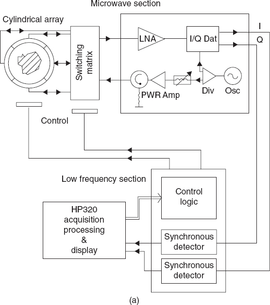

FIGURE 9.1 Prototype of a cylindrical microwave tomographic scanner: (a) scheme and (b) picture of the apparatus. [Reproduced from L. Jofre, M. S. Hawley, A. Broquetas, E. Reyes, M. Ferrando, and A. R. Elias-Fusté, “Medical imaging with a microwave tomographic scanner,” IEEE Trans. Biomed. Eng. 37(3), 303–311 (March 1990), © 1990 IEEE.]
Similar imaging prototypes and apparatuses have been developed by various research groups for different applications. Despite the similarities, they can exhibit different technical solutions related to any aspect of the design. A few examples are mentioned and related literature sources are cited in the following paragraphs.
The first example involves the imaging system developed for medical imaging by Semenov et al. (2000), which is constituted by antenna elements located inside a chamber of diameter 60cm and height 40cm, which is filled with deionized water (εr = 78 − j0.2 at 2.36 GHz) or salt solution (εr = 79 − j21.5 at 2.36 GHz). The distance between the transmitting antenna and the center of the chamber is 17.9 cm. A receiving antenna is moved around the target at a distance of 11 cm.
Simpler microwave systems can be constructed by using two moving antennas that rotate around the body to be inspected in order to retrieve bistatic scattering data. In this case, the efficiency of the PC-controlled mechanical systems is quite important for fast data acquisition. An example is the prototype of imaging tomograph developed at the Department of Technology and Innovation, University of Applied Sciences of Southern Switzerland (SUPSI), Manno, Switzerland, which is aimed in particular at imaging wooden objects, although other materials with similar dielectric properties could be inspected as well. The choice of operating frequency and power level was optimized for the specific application and considering a standard power levels available from network vector analyzers (≤ 10 dBm). For the first laboratory tests, off-the-shelf horn antennas have been used with typical gains of 8–10 dB, resulting in scattering signals with sufficiently high power levels to be easily detected by a standard network vector analyzers (–30 dBm or better). Some information about the external surface of the object under test is obtained by a time-domain analysis of the reflected signal S11 (single-antenna operation). In another version of the prototype, the laboratory equipment (the network vector analyzer) has been replached by a low-power short-range microwave radar that generates pulsed or frequency-swept microwave signals (with a center frequency of 5.5 GHz and a signal level of –30 dBm), which are radiated and received by single horn antennas. The result is a graphical representation (obtained by graphical software mapping the time of flight of the reflected radar signal) of the contours of the samples (e.g., wood trunks). The experimental setup is shown in Figure 9.2. Other examples of similar approaches are the prototype shown in Figure 9.3 (Bindu and Mathew 2007) and the scheme for the indirect holography of Figure 9.4 (Elsdon et al. 2006).
Another comparable setup is the one used at the Second University of Naples, Italy, which works in a reflection mode in the X band (Soldovieri et al., 2005). The transmitting and receiving antennas are two pyramidal horns located on two separate linear rails (140 cm long), which can be moved perpendicularly to the cylinder axis when a cylindrical scatterer is to be inspected. The measurement data are collected by using a vector network analyzer.
An important task in imaging systems is the calibration, especially for array-based systems. In fact, the measurements performed by such systems usually needs suitable calibration procedures to compensate for amplitude or phase dispersions in the responses of the various antennas in the array. Different modalities are used to perform the calibration, and the reader is referred to the wide literature concerning microwave measurements and antennas.
For microwave imaging applications, however, the calibration procedure can involve the use of a known object (typically, a canonical scatterer) that produces a prescribed scattered field pattern. Since the field that this object should produce at any measurement position is known, it is possible to calculate the weighting coefficients to be applied to each receiving element by comparing the expected field values with the actual ones produced by the calibrating scatterer. As an example of this approach, a metallic circular cylinder (diameter 4 cm) positioned at the center of the investigation area was used to calibrate the previously described 64-element array (Joachimowicz et al. 1998).
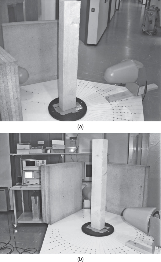
FIGURE 9.2 Experimental setup for inspecting wood objects (including a hollowed wood slab). [Courtesy of A. Salvadé, R. Monleone, and co-workers, Department of Technology and Innovation, University of Applied Sciences of Southern Switzerland (SUPSI), Manno, Switzerland.]
It should be mentioned that phase retrieval techniques, which have been widely used for diagnostic purposes of antennas, can be also used for imaging applications (Hislop et al. 2007), mainly at the highest frequencies [e.g., in the recently explored terahertz (THz) band]. By using this technique, one can derive the phase of the field in the observation domain from measurement of the field amplitude. In this way, direct measurement of the phase of the field at the measurement points is not required. The problem is that the phase retrieval process involves the solution of another ill-posed inverse problem. The description of such an inverse problem is outside the scope of the present book, and the reader is referred, for example, to the papers by Isernia and Pierri (1995) and Las-Heras and Sarkar (2002) and references cited therein.
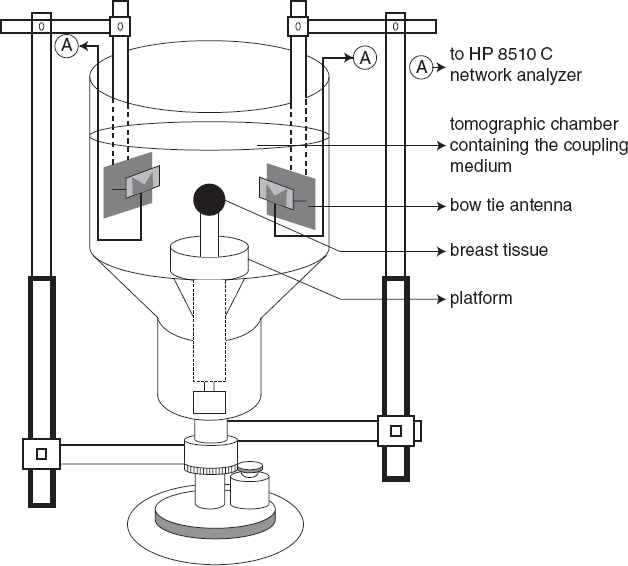
FIGURE 9.3 Experimental setup for two-dimensional microwave tomographic imaging. [Reproduced from G. Bindu and K. T. Mathew, “Characterization of benign and malignant breast tissues using 2-D microwave tomographic imaging,” Microwave Opt. Technol. Lett. 49, 2341–2345 (2007), © 2007 Wiley.]
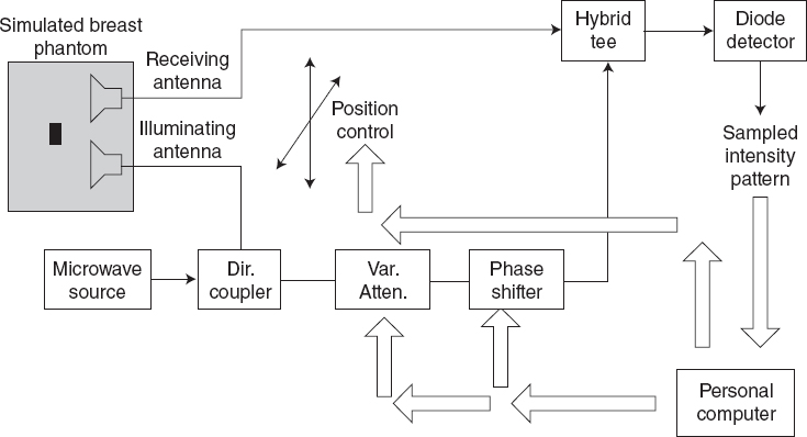
FIGURE 9.4 Experimental arrangement for indirect microwave holographic imaging. [Reproduced from M. Elsdon, D. Smith, M. Leach, and S. J. Foti,”Experimental investigation of breast tumor imaging using indirect microwave holography,” Microwave Opt. Technol. Lett. 48(3), 480–482 (2006), © 2006 Wiley.]
Finally, it must be observed again that many prototypes and measurement systems are currently used for various microwave imaging applications. Detailed descriptions of most of them can be found in the books and papers mentioned in the sections devoted to applications (Chapter 10).
9.3 ANTENNAS FOR MICROWAVE IMAGING
Concerning the transmitting and receiving antennas for imaging systems, the choice depends again on the configuration. Several tomographic systems use dipoles, which ensure a wide beamwith in the azimuthal plane and an acceptably narrow beamwidth in the elevation.
Of particular interest is the case in which wideband systems are used. For example, in the medical field (Section 10.2), the antennas must be small and must operate in an ultrawide range of frequencies in order to achieve good spatial resolutions and suitable penetrations of the field into the biological tissues. Other applications concern the field of nondestructive testing and evaluation. In such cases, one of the most frequently used antennas is the Vivaldi antenna (Fig. 9.5) (Chiappe and Gragnani 2006). A modified version of this antenna is the balanced antipodal Vivaldi antenna (Fig. 9.6) (Bourqui et al. 2007), which has been used even for detecting subsurface bodies. In this area, Vivaldi antennas working in the band 1.3–2.0 GHz have been designed, constructed, and tested (Pichot et al. 2004).
Another widely used antenna for imaging system is the bowtie antenna (Balanis 2005). Resistively loaded bowtie antennas have been proposed (Fear et al. 2003, Kubota et al. 2008), whereas a 2 × 2 array of bowtie antennas has been designed (Hernández-López et al. 2003) in order to minimize the mutual coupling between the antennas up to a negligible level. For example, Figure 9.7a shows the 2 × 2 array, in which 2-cm bowtie antennas are printed on a 4-mm-thick lossy substrate (εr ≈ 1 and σ = 10S/m), which minimizes the coupling between the array elements and enhances the broadband characteristics of the antenna. The elements of the array are excited (through coaxial transmission lines) by a signal in the 1.6–11.4 GHz band (the signal is expressed by a time derivative of a Gaussian pulse). Figure 9.7b provides the parameters of the scattering matrix obtained in the two cases in which the antennas are located in free space and when they are printed on the dissipative substrate (Hernández-López et al. 2003). As expected, the presence of the substrate significantly reduces the mutual coupling among the antenna elements. Furthermore, the lossy substrate also increases the bandwidth. This can be observed in Figure 9.7c, in which the reflected voltage at the feeding point of one of the array elements is shown for the two cases (free space and dissipative substrate).
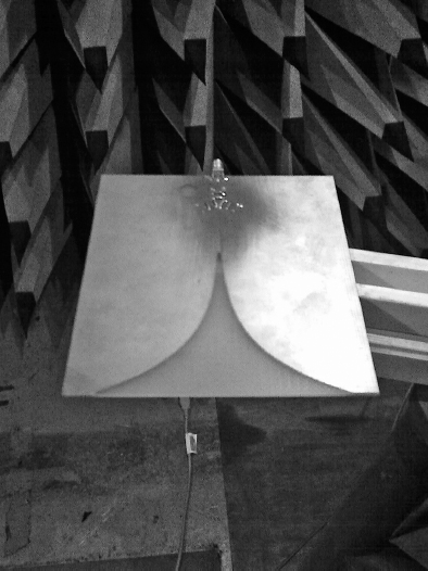
FIGURE 9.5 Vivaldi antenna. (Courtesy of G. L. Gragnani, University of Genoa, Italy.)
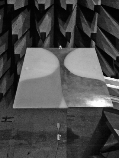
FIGURE 9.6 Antipodal Vivaldi antenna. (Courtesy of G. L. Gragnani, University of Genoa, Italy.)
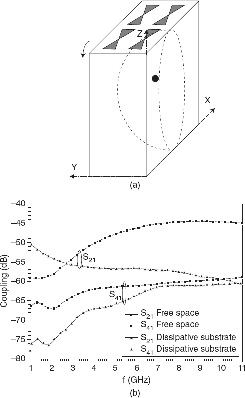
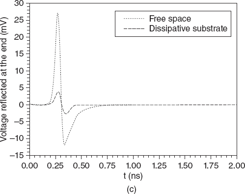
FIGURE 9.7 (a) Array of bowtie antennas located around a model of a human breast: (b) coupling coefficients for the planar array configuration; (c) reflected voltage at the center of the bowtie antenna. [Reproduced from M. A. Hernández-López, M. Quintillán-González, S. González García, A. Rubio Bretones, and R. Gómez Martín, “A rotating array of antennas for confocal microwave breast imaging,” Microwave Opt. Technol. Lett. 39, 307–311 (Nov. 20, 2003), © 2003 Wiley.]
Other antennas considered are straight thin-wire dipole antennas (Fear and Stuchly 2000), planar monopoles (Jafari et al. 2007), transverse electromagnetic (TEM) horn antennas, which are traveling-wave structures consisting of two conducting plates (Amineh et al. 2009), “dark eyes” antennas (Kanj and Popovic 2005), and V-antennas (Fernandez Pantoja et al. 2002).
Concerning the important application of microwave imaging in the detection of damage in concrete structures, a significant example is represented by the use of a planar array of microstrip slot antennas shown in Figure 9.8 (Kim et al. 2003). These microstrip slot antennas were selected because they could be directly attached to the concrete surface or the matching cushion.
Patch antennas are proposed even in the most recent imaging systems. One of them is an imaging prototype constituted by 36 patch antennas fabricated on low-loss dielectric material, which has been designed into a “bra-shaped semi-conformal chamber that can be directly attached to the patient's breast” (Stang et al. 2009).
Finally, further information concerning antennas for microwave imaging applications can be obtained in the contributed chapter by C. Furse (Furse 2007).
9.4 THE MODULATED SCATTERING TECHNIQUE AND MICROWAVE CAMERAS
There has been significant interest in applying the modulated scattering technique (Richmond 1955), which is as an efficient method for measuring electromagnetic fields not only for imaging applications but also in several other areas, including antenna testing and electromagnetic compatibility. The reader is referred to the text by Bolomey and Gardiol (2001) for a comprehensive description of this technique with in-deepth discussions of any technical issues and applications. The basic principle of the modulated scattering technique is briefly summarized as follows. The basic idea is that a passive probe (or an array of passive probes), when irradiated by an incident electromagnetic field, scatters (under specific loading conditions) a field that is directly related to the unperturbed field at the point where the probe is located.
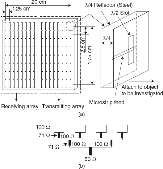
FIGURE 9.8 Planar rectangular microwave antenna array: (a) conceptual design of planar rectangular slot antenna array; (b) eight-element linear array with corporate feed configuration. [Reproduced from Y. J. Kim, L. Jofre, F. De Flaviis, and M. Q. Feng, “Microwave reflection tomographic array for damage detection of civil structures,” IEEE Tran. Anten. Propag. 51(11), 3022–3032 (Nov. 2003), © 2003 IEEE.]
Collecting this scattered field may result in an efficient measurement technique with a reduced perturbation of the original field distribution to be measured. Moreover, by using a scanning modulation, when an array of probes is used, one can collect a large number of field values with only a microwave receiver with no metallic connection with the probes or any moving mechanical apparatus.
There are two different configurations for implementing the modulated scattering technique: (1) the bistatic configuration, in which the receiving antenna is separated from the transmitting antenna, and (2) the monostatic configuration, in which the two antennas coincide. The passive probe is usually a dipole, but slot antennas have also been used more recently.
Let us first consider the bistatic arrangement for which the key relationship can be justified in terms of the scattering properties of passive antennas (Azaro et al. 1998a,b; Pastorino 2004). To this end, let us consider an incident field Einc produced by a given transmitting antenna. A receiving antenna (located at point rRX) collects the field obtained by the interaction of Einc with the scatterer and the probe antenna (located at point rP), which is assumed here to be a small dipole. The field collected by the receiving antenna can be expressed as
![]()
where E is the total field resulting from the interaction of the incident field with the target and is as given by equation (2.7.2). Essentially, E represents the incident field on the small probe, whereas EPscat is the field scattered by the probe. Since E is solenoidal, it can be expanded as follows (Stratton 1941)
![]()
where Mγpq and Nγpq denote spherical vector wavefunctions. The superscript γ indicates that the summation is performed over all the even (when γ = e) and odd (when γ = o) modes. Since we assume here that the probe is a small electric dipole polarized along the x axis, it strongly interacts only with the Ne11(r) mode, which is given by
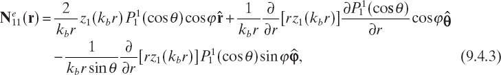
where z1(kbr) is the spherical Bessel function of the first kind and P11 = sin θ is the associated Legendre function. If the load ZL is placed at a point where the impedance looking toward the probe is purely resistive and of value RP, the power scattered by the probes can be expressed as (Collin 1969, Hansen 1989) follows:
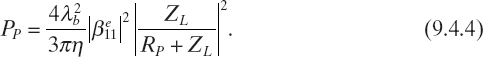
The key idea of the modulated scattering technique is to change, using a modulating signal, the value of the load impedance ZL. According to equation (9.4.4), the scattered power also changes. In particular, when matched, the dipole scatters as much power as absorbed. In this case, the scattered electric field at the receiving antenna can be expressed as
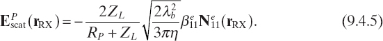
Finally, the open-circuit output voltage at the receiving-antenna terminals can be expressed as (Balanis 2005)
![]()
where hRX the complex effective length of the receiving antenna. According to equation (9.4.1), equation (9.4.6) can be immediately rewritten as
![]()
where the term hRX · Etot · (rRX) is an unmodulated component of the output voltage, which can be simply removed, whereas the other term, hRX · EPscatt (rRX), is just proportional, according to equations (9.4.5) and (9.4.2), to the x component of the E at the probe location rP.
A different approach is followed for the monostatic configuration, which is related essentially to the imaging modalities defined in Chapter 4. The key relationship of the monostatic configuration is discussed below (Azaro et al. 2003), considering the fact that there are now only one active antenna and the passive probe.
Let us consider Figure 9.9a, in which “P” denotes the probe, loaded by a complex impedance, and “TX” indicates the transmitting antenna (transmission mode). In applying the monostatic approach, the following relation is used (Azaro et al. 2003):
![]()
This is an expression of the Lorentz reciprocity theorem (Monteath 1973). In equation (9.4.8), S is a surface consisting of S1 and S2 (reference surfaces in the transversal planes of the waveguides), S0 (PEC surface lying outside the antennas and extended on the inner surfaces of the antennas and waveguide up to S1 and S2), and S∞ (the surface at infinity). Moreover, the two fields, denoted by subscripts a and b. represents two different field distributions obtained by imposing two different values to the load ZL. In particular, a is the field in the case in which ZL = ∞ (open circuit), and b refers to the matching load (Fig. 9.9b).
For a minimum-scattering antenna, the functional state a corresponds to an almost invisible antenna, whereas in the matched-load case, the probe scatters an amount of power equal to that transferred to the load (Collin 1969). According to the notation in Figure 9.9, the following relations hold for incident and reflected currents and voltages in the two states a and b:
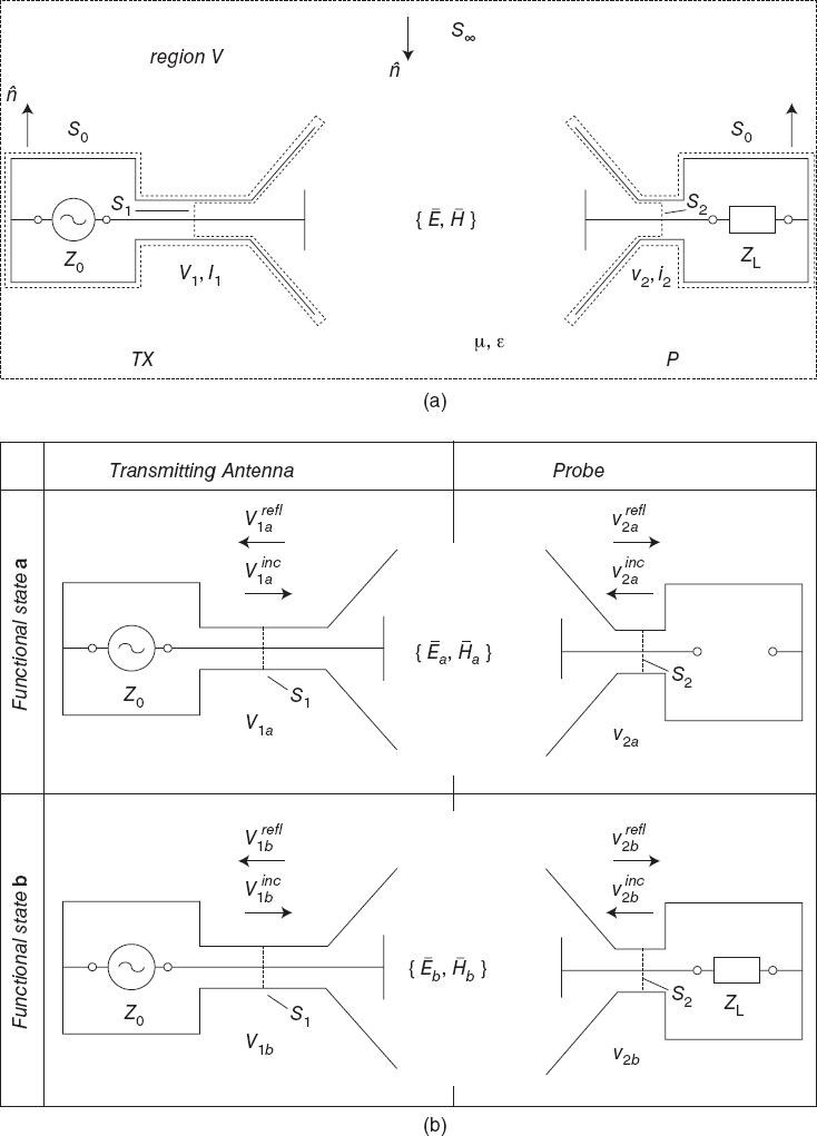
FIGURE 9.9 (a) Schematic representation of the monostatic modulated scattering technique; (b) currents and voltages of the two different functional states. [Reproduced from R. Azaro, S. Caorsi, and M. Pastorino, “On the relationship for the monostatic modulated scattering technique,” Microwave Opt. Technol. Lett. 38, 187–190 (2003), © 2003 Wiley.]
![]()
![]()
![]()
Moreover, assuming the electromagnetic field inside the waveguides to be represented by a single propagation mode, the transversal components of the fields on S1 and S2 can be expressed as (Montgomery et al. 1948)
![]()
![]()
where et(rt) and ht(rt) are real-valued transversal functions such that
![]()
Since S0 is a PEC surface and the fields are vanishing on S∞, it follows that
![]()
and, by using (9.4.13) and (9.4.14), we obtain

which can be rewritten as
![]()
Taking into account (9.4.15), we have
![]()
Let us consider now the functional state a, which is characterized by
![]()
![]()
![]()
![]()
![]()
It also follows that
![]()
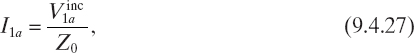
where Z0 is the characteristic impedance of the feeding waveguide. Analogously, in the functional state b, we have
![]()
![]()
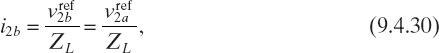
and we obtain
![]()
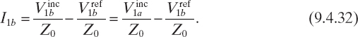
From (9.4.19)−(9.4.32) it follows that

and
If we consider the antenna factor of the small probe, we can express the field at input port of the receiving antenna in functional state b as
![]()

which is the key relation for the modulated scattering technique in the monostatic mode. By using the modulated scattering technique, microwave cameras can be developed. One of the first proposed and most effective apparatuses of this kind was been developed by Franchois et al. (1983, 1998).
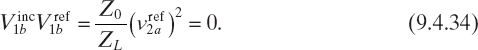
However, a simple scheme of a measurement system based on the modulated scattering technique can be found in Figure 9.10a. The measurement system is composed of three different sections: the first one operates at microwave frequencies and is used to generate the incident electromagnetic field and demodulate the signal received at the receiving antenna (RX); the second and the third ones operate at low frequency. In particular, the second one is used to generate the modulation signal and send it to the field probes. The third one is used to control the system and process the obtained data. The electromagnetic field is generated by means of a sine-wave generator connected to an amplifier. The signal is divided by means of a directional coupler.
One part is sent to the transmitting antenna (TX), and the other is used for the reference channel. The transmitter is a λ/4-dipole antenna (where λ/4 is the wavelength) with a plane rectangular reflector placed at a distance of λ/4 from the radiator. Since the distance between the transmitting antenna and the investigation area can be changed, near-field and far-field radiation conditions can be achieved. In the last case, the signal in the investigation area can be assumed as an acceptable approximation of a transverse magnetic planar wave impinging on the scatterer. The passive array is constituted by λ/4-dipole probes (Fig. 9.10b). Each probe is loaded with a phototransistor, which acts as a nonlinear load. The electronic driving is obtained by sending to the probes an optical signal by means of an optical-fiber connection. The modulation signals are square waves with periods equal to 1 ms. A crystal oscillator generates the modulation signals, which are converted into optical signals by using emitting photodiodes. Since the experimental system is based on the modulated scattering technique in the bistatic configuration, the signals used for the measurements (which are proportional to the field values at probe positions) are finally collected by the receiving antenna, which is an aperture antenna (with a beamwidth of ∼120° in the azimuth plane). Because of the low level of the scattering signal, a low-noise microwave amplifier is connected to the receiving-antenna output. The probe array, the receiving antenna, and the optical connections are assembled together by means of a dielectric frame in order to limit the field perturbations (Fig. 9.10b). Figure 9.11 gives an example of measured data in the case of the PEC circular cylinder reconstructed using the memetic algorithm and described in Section 8.2.
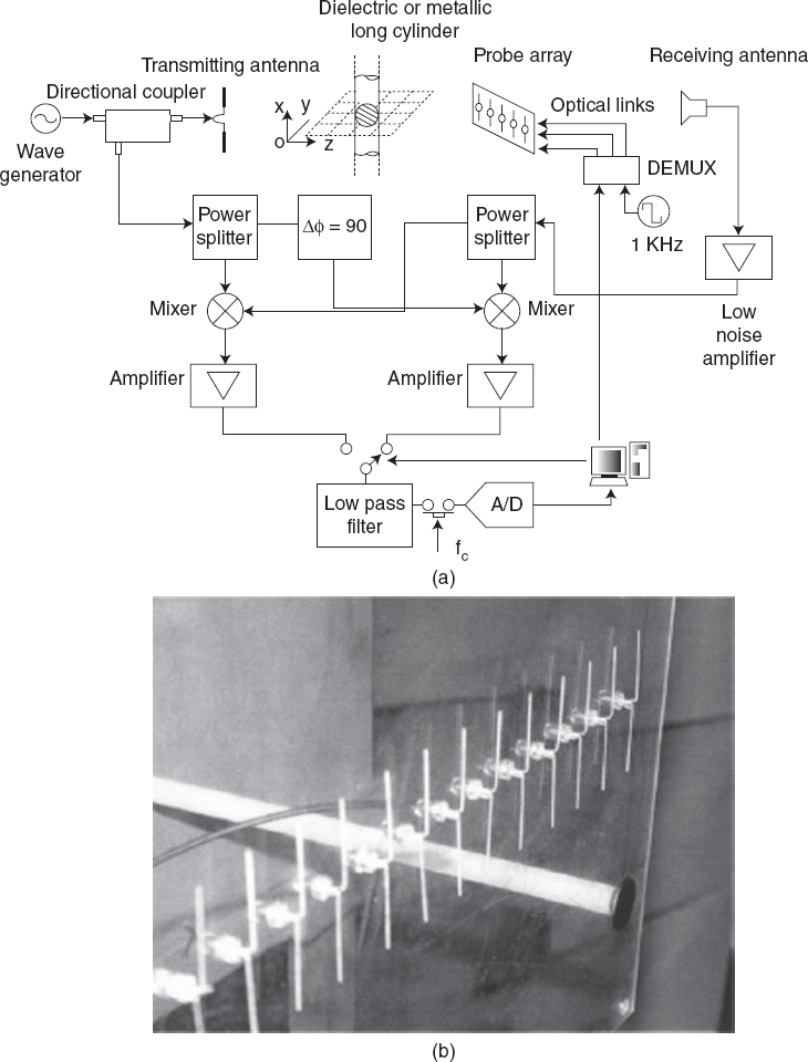
FIGURE 9.10 (a) Experimental setup of an imaging system based on the modulated scattering technique; (b) array of passive probes (dipoles). [Reproduced from S. Caorsi, M. Donelli, and M. Pastorino, “A passive antenna system for data acquisition in scattering applications,” IEEE Anten. Wireless Propag. Lett. 1, 203–206 (2002), © 2002 IEEE.]
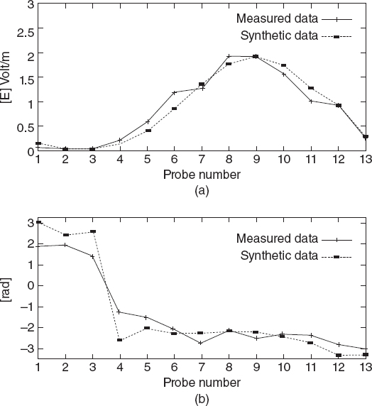
FIGURE 9.11 Scattering by a perfectly conducting circular cylinder: (a) amplitude and (b) phase values of the scattered electric field measured by the 13 probes of the imaging system in Figure 9.10, positioned at x = 0.0. Comparison with analytical data. [Reproduced from S. Caorsi, M. Donelli, and M. Pastorino, “A passive antenna system for data acquisition in scattering applications,” IEEE Anten. Wireless Propag. Lett. 1, 203–206 (2002), © 2002 IEEE.]
The modulated scattering technique has also been used to develop a very effective two-dimensional imaging system capable of rapid measurements of amplitude and phase of the electromagnetic field at 24 GHz in the K band (Ghasr et al. 2008). It consists of an array of 30 high-Q resonant slots loaded with PIN diodes. The probes can be modulated sequentially or simultaneously. The element spacing is λ/2, where λ is the wavelength of the operating frequency.
The key parameters of the systems are the switching speed and the modulation depth (which is the difference between the measured amplitudes of the signal in the two states of the PIN diode). Figure 9.12 shows the measurement setup, whereas Figure 9.13 presents an example of the measured field distribution (amplitude and phase) in the case in which a small PEC sphere is inspected.
FIGURE 9.12 Measurement setup showing the waveguide transmitter, a small metallic sphere in front of the array, and the slot array. [Reproduced from M. T. Ghasr, M. A. Abou-Khousa, S. Kharkovsky, R. Zoughi, and D. Pommerenke, “A novel 24 GHz one-shot rapid and portable microwave imaging system,” Proc. IEEE Int. Instrumentation and Measurement Technology Conf. (I2MTC 2008), Victoria, Vancouver Island, Canada, May 12–15, 2008, pp. 1798–1802, © 2008 IEEE.]
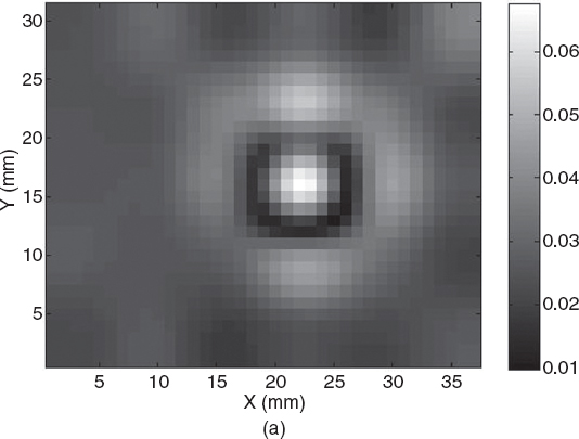
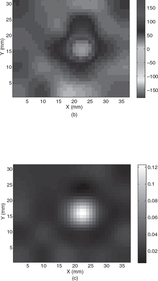
FIGURE 9.13 (a) Magnitude and (b) phase (degree) of measured scattered electric field from a metallic sphere 10 mm in diameter at a distance of 10 mm from the array (Fig. 9.12) in reflection mode. In (c) the data are SAF-processed to produce a precise image of the sphere. [Reproduced from M. T. Ghasr, M. A. Abou-Khousa, S. Kharkovsky, R. Zoughi, and D. Pommerenke, “A novel 24 GHz one-shot rapid and portable microwave imaging system,” Proc. IEEE Int. Instrumentation and Measurement Technology Conf. (I2MTC 2008), Victoria, Vancouver Island, Canada, May 12–15, 2008, pp. 1798–1802, © 2008 IEEE.]
REFERENCES
Amineh, R. K., A. Trehan, and N. K. Nikolova, “Ultra-wide band TEM horn antenna designed for microwave imaging of the breast,” Proc. 2009 Int. Symp. Antenna Technology and Appl. Electromagn. (ANTEM/URSI), Banff, Canada, 2009.
Azaro, R., S. Caorsi, and M. Pastorino, “A 3-GHz microwave imaging system based on a modulated scattering technique and on a modified Born approximation,” Int. J. Imag. Syst. Technol. (Wiley) 9(5), 395–403 (1998a).
Azaro, R., S. Caorsi, and M. Pastorino, “On the relationship for the bistatic modulated-scattering technique in scattering applications using scattering properties of antennas,” IEEE Trans. Anten. Propag. 46(9), 1399–1400 (1998b).
Azaro, R., S. Caorsi, and M. Pastorino, “On the relationship for the monostatic modulated scattering technique,” Microwave Opt. Technol. Lett. 38, 187–190 (2003).
Balanis, C. A., Antenna Theory: Analysis and Design, Wiley, New York, 2005.
Bindu, G. and K. T. Mathew, “Characterization of benign and malignant breast tissues using 2-D microwave tomographic imaging,” Microwave Opt. Technol. Lett. 49, 2341–2345 (2007).
Bolomey, J.-C. and F. E. Gardiol, Engineering Applications of the Modulated Scatterer Technique, Artech House, 2001.
Bourqui, J., M. Okoniewski, and E. C. Fear, “Balanced antipodal Vivaldi antenna for breast cancer detection,” Proc. 2nd Eur. Conf. Antennas and Propagation, Edinburgh, UK, 2007.
Chiappe, M. and G. L. Gragnani, “Vivaldi antennas for microwave imaging: Theoretical analysis and design considerations,” IEEE Trans. Instrum. Meas. 55, 1885–1891 (2006).
Collin, R. E., “The receiving antenna,” in Antenna Theory, Part 1, R. E. Collin and F. J. Zucker, eds., McGraw-Hill, New York, 1969.
Elsdon, M., D. Smith, M. Leach, and S. J. Foti, “Experimental investigation of breast tumor imaging using indirect microwave holography,” Microwave Opt. Technol. Lett. 48, 480–482 (2006).
Fear, E. C., P. M. Meaney, and M. A. Stuchly, “Microwaves for breast cancer detection?” IEEE Potentials 22, 12–18 (2003).
Fear, E. C. and M. A. Stuchly, “Microwave detection of breast cancer,” IEEE Trans. Microwave Theory Tech. 48, 1854–1863 (2000).
Fernandez Pantoja, M., S. Gonzalez Garcia, M. A. Hernandez-Lopez, A. Rubio Bretones, and R. Gomez Martin, “Design of an ultra-broadband V-antenna for microwave detection of breast tumors,” Microwave Opt. Technol. Lett. 34, 164–166 (2002).
Franchois, A., A. Joisel, N. Joachimowicz, J.-C. Bolomey, and Ch. Pichot, “Nonlinear iterative reconstruction algorithm for a 2.45-GHz planar microwave camera,” Proc. 2nd Int. Scientific Meeting IEEE-URSI Microwaves in Medicine, Rome, Italy, 1983, pp. 263–266.
Franchois, A., A. Joisel, Ch. Pichot, and J.-C. Bolomey, “Quantitative microwave imaging with a 2.45-GHz planar microwave camera,” IEEE Trans. Med. Imag. 17, 550–561 (1998).
Furse, C., “Antennas for medical applications,” in Antenna Engineering Handbook, J. Volakis, ed., McGraw-Hill, New York, 2007.
Ghasr, M. T., M. A. Abou-Khousa, S. Kharkovsky, R. Zoughi, and D. Pommerenke, “A novel 24 GHz one-shot, rapid and portable microwave imaging system,” Proc. IEEE Instrumentation and Measurement Technology Conf., Victoria, Vancouver Island, Canada, 2008, pp. 1798–1802.
Hansen, R. C. “Relationships between antennas as scatterers and as radiators,” Proc. IEEE 77, 659–662 (1989).
Hernández-López, M. A., M. Quintillán-González, S. González García, A. Rubio Bretones, and R. Gómez Martín,” A rotating array of antennas for confocal microwave breast imaging,” Microwave Opt. Technol. Lett. 39, 307–311 (2003).
Hislop, G., G. C. James, and A. Hellicar, “Phase retrieval of scattered fields,” IEEE Trans. Anten. Propag. 55, 2332–2341 (2007).
Isernia, T. and R. Pierri, “Phase retrieval of radiated fields,” Inverse Problems 11, 183–203 (1995).
Jafari, H. M., M. J. Deen, S. Hranilovic, and N. K. Nikolova, “A study of ultrawideband antennas for near-field imaging,” IEEE Trans. Anten. Propag. 55, 1184–1188 (2007).
Joachimowicz, N., J. J. Mallorqui. J. C. Bolomey, and A. Broquetas, “Convergence and stability assessment of Newton-Kantorovich reconstruction algorithms for microwave tomography,” IEEE Trans. Med. Imag. 17, 562–570 (1998).
Jofre, L., M. S. Hawley, A. Broquetas, E. de los Reyes, M. Ferrando, and A. R. Elias-Fusté, “Medical imaging with a microwave tomographic scanner,” IEEE Trans. Biomed. Eng. 37, 303–311 (1990).
Kanj H. and M. Popovic, “Miniaturized microstrip-fed “dark-eyes” antenna for near field microwave sensing,” IEEE Anten. Wireless Propag. Lett. 4, 397–401 (2005).
Kim, Y., J. L. Jofre, F. De Flaviis, and M. Q. Feng, “Microwave reflection tomographic array for damage detection of civil structures,” IEEE Trans. Anten. Propag. 51, 3022–3032 (2003).
Kubota, S., X. Xiao, N. Sasaki, K. Kimoto, W. Moriyama, and T. Kikkawa, “Experimental confocal imaging for breast cancer detection using silicon on-chip UWB microantenna array,” Proc. 2008 Antennas Propagation Society Int. Symp., San Diego, CA, 2008.
Las-Heras F., and T. Sarkar, “A direct optimization approach for source reconstruction and NF-FF transformation using amplitude-only data,” IEEE Trans. Anten. Propag. 50, 500–510 (2002).
Monteath, G. D., Applications of the Electromagnetic Reciprocity Principle, Pergamon Press, New York, 1973.
Montgomery, G., R. H. Dicke, and E. M. Purcell, Principles of Microwave Circuits, McGraw-Hill, New York, 1948.
Pastorino, M., “Recent inversion procedures for microwave imaging in biomedical, subsurface detection and nondestructive evaluation,” Measurement 36, 257–269 (2004).
Pichot, C., J. Y. Dauvignac, C. Dourthe, I. Aliferis, and E. Guillanton, “Inversion algorithms and measurement systems for microwave tomography of buried objects,” Proc. IEEE Int. Workshop on Imaging Systems and Techniques, Stresa, Italy, 2004.
Richmond, J. H., “A modulated scattering technique for measurement of field distributions,” IRE Trans. Microwave Theory Tech. 3, 13–15 (1955).
Semenov, S. Y. et al., “Spatial resolution of microwave tomography for detection of the myocardial ischemia and infarction. Experimental study on two-dimensional models”, IEEE Trans. Microwave Theory Tech. 48, 538–544 (2000).
Soldovieri, F., A. Brancaccio., G. Leone, and R. Pierri, “Shape reconstruction of perfectly conducting objects by multiview experimental data,” IEEE Trans. Geosci. Remote Sens. 32, 65–71 (2005).
Stang, J. P. et al., “A tapered microstrip patch antenna array for use in breast cancer screening via 3D active microwave imaging,” Proc. 2009 Antennas Propagation Society Int. Symp., Charleston, SC, 2009.
Stratton, J. A., Electromagnetic Theory, McGraw-Hill, New York, 1941.
Microwave Imaging, By Matteo Pastorino
Copyright © 2010 John Wiley & Sons, Inc.