
5
Engineering Processes
5.1. Introduction
If we refer to the state of the art and to professional standards, different processes will be applied by a project team whose aim is to develop a technological system.
The name, designation and the way in which these processes are organized depend on the methodological context in which they are found. For example, engineering processes considered in the recommendation ARP4754A1 and standard EIA 632 [ANS 03] are not strictly identical for exactly this reason. Therefore, ARP4754A, recommended for the development of passenger transport aircraft and their subsystems, pays special attention to the safety assessment process, and to its dependencies and interactions with other aircraft development processes, although this process is not explicitly mentioned in other standards such as EIA632 or even ISO15288 [ISO 05].
Similarly, the concepts around which these development processes are organized also depend on the methodological context in which they are found. This is not surprising given the fact that these methodological frameworks involve technological knowledge systems and that the meaning of a concept is an emergent property of such an abstract system. For example, the term “validation” in the recommendation ARP4754A and standard ISO15288 refers to diametrically opposed concepts. In the first case, the validation is a process that involves ensuring that the system requirements are sufficiently correct and complete and that the assumptions made about the environment of the system are also sufficiently correct and complete. In the second case, ISO15288, the validation is a process that allows us to confirm, via a certain number of tests, that the requirements are satisfactory (“confirmation, through the provision of objective evidence, that the requirements for a specific intended use or application have been fulfilled”, ISO15288, section 4.23, p. 5).
In other words, development standards, such as EIA632, ISO15288 or even ARP4754A, are knowledge systems. These are technological knowledge systems in the sense that they state rules for technological process performance. Moreover, these rules are not substantial as those described in Chapter 3, as they are not derived from factual scientific laws. These engineering rules are operative rules (see section 3.6.3) defined to produce an effect, and they are based on scientific method as we can also see in works on operations research.
Moreover, in the infancy of systems engineering, Arthur D. Hall [HAL 62], considered as the father of this discipline, highlighted the current similarities between operations research and this new discipline which he called systems engineering:
The intellectual processes comprising the patterns of operations research and systems engineering show more similarities than differences. The phases of operations research listed by Churchman et al. are as follows:
The similarities with the phases of systems engineering are obvious. This is not surprising since both are elaboration of modern scientific method applied to different ends.
These standards have many similarities, but they are not necessarily the same. They may be more or less coherent, more or less complete, which is why we will find our own way through the different recommendations they provide. This is how we will proceed in the following chapters.
5.2. Systems engineering process
5.2.1. General framework
In this section, we introduce the general framework that is referred to in this book, namely the eight processes defined by ARP4754A (see Figure 5.1).
The planning process forms the basis of systems engineering processes according to ARP4754A. They anticipate that, for each process identified, a plan is established and followed throughout the whole development or redevelopment process. These plans will be followed; the variances shall be recorded and the plans shall eventually be revised.
Figure 5.1. ARP4754A engineering processes
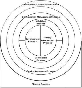
The seven other processes are organized and displayed according to an onion skin model: (1) development and (2) safety assessment are in the center and are presented as two halves of a disk to illustrate an objective of perfect integration. Around these two core processes, the following five processes are evolved: (3) the validation process of requirements and assumptions, which is located upstream and (4) the verification process of implementation that is downstream. In this onion skin description, these two processes are then successively followed by (5) the configuration management process for the system under development or redevelopment, (6) the quality assurance process (more specifically, process assurance) and (7) the certification process that organizes the compliance demonstration of the installed system with the airworthiness regulations.
5.2.2. Design process
Nevertheless, the development process described in ARP4754A is only a fairly general process (ED79A/ ARP4754A, Chapter 4 page 16), and we consider that this process needs to be described in more detail. We aim to do this by quite simply referring to the standard ANSI/EIA632 that proposes an iterative design process for a system by working through the activities at each stage of the design process as detailed below.
A technological system is composed of an assembly of building blocks, as shown in Figure 5.2.
Figure 5.2. EIA632 system breakdown structure
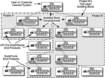
For each of these building blocks, the same design process is applied, except for the terminal blocks.
The terminal blocks are either off the shelf or reused, such as equipment issued with a letter of approval TSO2 or ETSO3, or blocks directly manufactured or coded (for software).
The design process for each block involves two subprocesses:
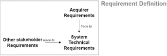
The first subprocess involves the following tasks:
Figure 5.3. EIA632 building block requirement definition subprocess
The second subprocess involves the following tasks:
Figure 5.4. EIA632 building block solution definition subprocess
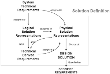
Inputs and outputs: the inputs of these two subprocesses are the technical requirements of the system and the outputs are the specific requirements of the design solution.
Assigning the technical requirements of a system: the upstream requirements are assigned according to their nature (structural or behavioral requirement) to the logical solution (for example, a functional, performance, time response and accuracy requirement) or directly to the physical solution (for example, weight requirement, size and geographical location). This is the requirement assignment process to the logical and physical solutions.
Technical requirement derivation process of a system: once assigned to a logical or physical solution, these requirements are derived and assigned to different elements of a logical (respectively, physical) solution. As shown in Figure 5.4, the logical and physical solutions determine the requirement derivation process. This means that the derived requirements depend not only on the requirements from which they derive, but also on the solution (logical or physical). In other words, there is no derived requirement that does not depend on the design solution in which this requirement was formed, except perhaps when it comes to poor requirement engineering practices.
Assigning elements of a logical solution to those of a physical solution: finally, elements of a logical solution, accompanied by derived requirements, are assigned to the physical solution. It results in a design solution that describes all components and physical links of the solution, elements of a logical solution (functional) that have been assigned to each one, as well as the behavioral (logical) and structural (physical) requirements assigned to them. The requirements assigned to each element of a design solution are specified requirements.
Figure 5.5. EIA632 building block design processes
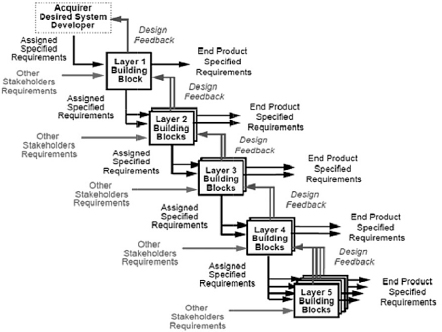
In the case of a multilevel system, the process begins at the highest level of the system. It is then repeated for each building block for which, at the input of each block at level n, there are acquirer requirements and other stakeholder requirements, whereas at the output, there are requirements specific to the components forming the design solution of the block at level n. The process terminates at the lowest level blocks. These blocks, at the lowest level, are either blocks available from an equipment manufacturer, such as an equipment manufacturer under TSO/ETSO, or blocks that will be developed or modified according to a specification by an external or internal supplier, or even, directly codable blocks (software) or directly manufactured without other design activity.
5.2.3. Safety assessment process
These processes involve the different analyses such as:
Figure 5.6. ARP4754A safety assessment and system development process integration
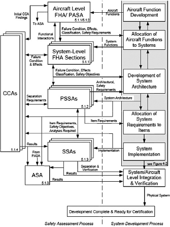
ARP4754A highlights the necessity of carrying out the developmental and safety assessment tasks in an integrated manner to keep the applicable requirements consistent as well as with the design choices and safety analyses to which they refer. This is shown in Figure 5.6.
To meet the integration requirement of safety assessments activities and those of requirement definition and solution definition, we propose an extension of the framework provided by EIA 632 by introducing safety assessment tasks at each design block level.
Figure 5.7. EIA 632 design process extended to safety assessment topics
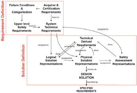
As far as the requirement definition process associated with the considered block is concerned, we propose adding a safety requirement collection activity, conducted as part of the system’s technical requirement definition, and based on functional hazard assessment (FHA) carried out at the level of the building block.
However, for the solution definition process associated with a given block, we propose formulating a solution for safety assessment (such as dependence diagrams and fault trees) of the considered block. The elements of a physical solution include the solution framework for safety assessment, i.e. the associated dependence diagram (or reliability block diagram). The safety requirements belonging to the technical requirements of a system are generally assigned to these representations and may be derived and assigned to different elements of a physical solution. The design solution as well as the requirements specific to each element of a design solution may have additional safety requirements assigned to them.
5.2.4. Requirement and assumption validation
ARP4754A recommends carrying out a validation of the requirements and assumptions at each decomposition level of a system by preferably beginning with the highest level; we will describe requirements and assumptions in more detail in Chapter 6.
The purpose of this validation process is to guarantee that the technical requirements of the system, as well as the specified requirements, are as correct and complete as possible, at each decomposition level of the system, and therefore the system under development is the desired system and the development equipment is appropriate for the purpose. Similarly, all assumptions regarding the definition of these requirements shall also be validated.
“The requirements shall be sufficiently complete” means that overlooked requirements should not make the system unacceptable to the stakeholders “(the client, user, authorities etc.)”. They shall also be sufficiently correct, that is to say they shall comply with the requirements to satisfy the desired type of system.
The validation process of requirements and assumptions of a system is a long and costly process. However, it is less costly than developing a type of systems inappropriate for the intended service. At the highest level, the validation of requirements and assumptions is more of a marketing, financial and regulatory problem; therefore, it has more to do with economic and social engineering than the engineering of technological systems. However, once this first stage achieved, the validation of requirements and hypotheses is handed over to technological engineering. It is, therefore, more about showing that the derivation of system requirements has been correctly and completely carried out and that the derived requirements obtained correctly and completely cover the original requirements. This is what we propose to do in the validation chapter of this book.
Finally, ARP4754A recommends that the validation effort should be proportionate to the severity of failures of the developed systems and the validation tools, such as simulation, analysis, tests and expert judgments, are used gradually, and possibly in combination, according to the severity of the failures. Some of these tools, such as simulation, may be used early in the development cycle, whereas others, such as flight testing, are likely to be used later. Although they are complementary to each other, it is clear that creating a validation strategy, primarily concerning time-consuming methods, such as flight tests, is both risky and costly. This is the reason why we propose, in Chapter 8, a strategy that puts emphasis on simulation as an early validation means.
5.2.5. Verification of the implementation regarding requirements
ARP4754A recommends proceeding in a complimentary manner to requirement validation, a verification of the implementation facing the requirements, at each level of system decomposition.
The purpose of this verification process is to guarantee that the physical realization of each block conforms to the assigned requirements. With each level of requirements having been validated, we can also expect that the system obtained will conform to initial expectations.
The different stages of realization include design solutions of each block, the physical realization of each elementary block and the gradual integration of blocks, until the whole system is obtained. ARP4754A recommends that the verification focuses on all physical products. However, we consider that it should also involve products of design (design descriptions and design models).
Finally, ARP4754A recommends that the verification effort should be proportionate to the severity of failures of the developed systems and the verification means, such as simulation, analyses, inspections and expert judgments, should be used gradually, and possibly in combination, according to the severity of the possible failures. Some of these means, such as simulation, may be used early in the development cycle, whereas others, such as flight testing, are likely to be used later. Although they are complementary to each other, it is clear that creating a verification strategy, primarily concerning time-consuming methods, such as flight tests, is both risky and costly. This is the reason why we propose, in Chapter 9, a strategy that covers each stage of the implementation, including the design process.
5.2.6. Managing configurations
Although this topic is not widely discussed in this book, it is not a problem regarding the context of our approach; ARP4754A recommends implementing a configuration management process that assures controlled development. The configuration of definition products, the products implemented, the means of validation, implementation and verification shall be established and controlled. The corresponding data shall be archived and retrievable. Defects in the manufactured products shall be recorded as problem reports, the causes of these defects shall be located and errors in the product definition at the origin of these defects shall also be located and recorded. Changes may have several causes: (1) errors, (2) not related to errors but eventually to a change in the need or the context or even (3) a progressive development strategy by means of versions. These modifications shall undergo a process that allows the product configuration to evolve in a mastered way.
5.2.7. Process (quality) assurance, certification and coordination with authorities
ARP4754A recommends implementing a process (quality) assurance process that ensures conformity of all processes actually implemented in a system development project in relation to plans defined in the planning process (each process shall follow the plan assigned to it) in order to identify possible errors, and to follow actions to reduce those errors. At the same time, proof of its own activities shall be gathered.
Finally, ARP4754A recommends implementing a certification coordination process with the authorities, which allows the certification basis to be determined, and to together agree on the method of demonstrating the compliance of the system installed in an aircraft with the certification basis and to provide the authorities with evidence of this compliance to the established and agreed plan.
In this book, although we do not deal with these points, it is certain that what we do propose has a positive impact on certification processes and, in particular, on the demonstration of compliance with general requirements such as FAR25.1309, FAR27.1309 and FAR29.1309 in USA or CS25.1309, CS27.1309 and CS29.1309 in Europe.
1 EUROCAE ED79A/SAE ARP4754A, “Guidelines for development of civil aircraft and systems”, EUROCAE, France, December 2010.
2 TSO: Technical Standard Order. A TSO is a minimum performance standard for specified materials, parts and appliances used on civil aircraft issued by FAA.
3 ETSO: European Technical Standard Order issued by EASA.
4 We prefer the term “behavioral” to that of “functional” (see Chapter 6).