
7
Designing Solutions and Design Models
7.1. Introduction
As mentioned in the introductory Chapter 5, the composition of a technological system is made up of building blocks that its endo-structure assembles (see Figure 5.2, Chapter 5). The same design process is applied for each building block, except for terminal blocks that (1) do not require design, (2) are designed somewhere or (3) have already been designed.
The design process of each block is composed of two subprocesses:
In Chapter 6, we described the process of definition of the requirements assigned to the type of systems targeted. In this chapter, we will discuss on the second subprocess, that is to say defining one or more solutions.
We know that design problems are “inverse” problems, meaning that they can have multiple solutions, which is why we use the expression “definition of one or more solutions” rather than “definition of the solution”.
Figure 7.1. EIA632 building block solution definition subprocess
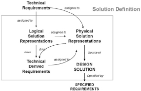
The definition of a design solution involves multiple activities: (1) design of a logical solution, (2) allocation and derivation of part of the technical requirements of the system to the logical solution under consideration, (3) design of a physical solution, (4) allocation of the logical solution, and of the requirements allocated to the logical solution, to the physical solution under consideration and (5) allocation and derivation of the pending technical requirements of the system to the physical solution under consideration. As indicated in Figure 7.1, the design subprocess leads to a design solution determined by the specified requirements of the subsystems.
However, before describing the subprocess of defining a solution, we will introduce the concept of derivation of property-based requirements (PBRs).
7.2. Deriving requirements
We propose a definition of the concept of derivation of requirements in this section. The definitions of this concept in standards show little homogeneity.
For the EIA632, a derived requirement is unambiguously a requirement “that is further refined from a primary source requirement or a higher-level derived requirement”1. For example, a subsystem requirement can be derived from a system requirement.
For ISO 15288, the definition of derived requirement is missing.
For ARP4754A, derived requirements are “additional requirements resulting from design or implementation decisions during the development process which are not directly traceable to higher-level requirements”2. However, problems are caused by the ambiguity of natural languages, what does “not directly traceable to” mean? It could mean, for example, that a derived requirement is an additional requirement resulting from a design choice (DC) and is traceable to a higher level requirement through the mediation of (therefore, indirectly) this DC. This is the interpretation provided by Scott Jackson3, John McDermid [MCD 03] and apparently the ARP 4761 [SAE 96]. It could mean, on the contrary, that a derived requirement cannot be linked to a higher level requirement. This is the chosen interpretation by many practitioners who sometimes campaign for the suppression of the adverb “directly” of the recommendation. We do not share this second point of view that does not rely on an explicit requirement theory and we adopt the point of view of EIA 632, Scott Jackson, etc., which is consistent with the signification of the word ‘derivation’ and our PBR theory.
In the theory of PBR, we decide to define the requirement derivation as a mechanism which, during the design process, enables the substitution of a PBR of system level by a conjunction of requirements (PBRs) assigned to its subsystems.
For such a derivation Rq →{Rq1,..,Rqn} to be true, the following formal relation shall be established:
[7.1] ![]()
Relationship [7.1] means that the conjunction of derived requirements Rqi assigned to the subsystems (sΣ1, , sΣn) of a system Σ shall be more constraining than the system requirement Rq from which they derive, provided that the DC has been respected.
For example, consider a system Σ with an electric consumption that shall be less than or equal to 1 kW when it is running (Σon). This immediately gives as a PBR
Rq: when Σon → Σ.Electrical_Consumption ≤ 1 kW
Suppose that the two alternate designs DC1 and DC2 are considered for the system Σ and the two designs are based on the two same components IT1 and IT2. The only difference is that in the first case (DC1 architecture), IT1 and IT2 work in alternation (passive redundancy, for example), whereas in the second case (DC2 architecture), IT1 and IT2 work simultaneously (active redundancy).
Finally, consider the two following requirements:
Rq1: when IT1.on → IT1.Electrical_Consumption ≤ 5.0 kW
Rq2: when IT2.on → IT2.Electrical_Consumption ≤ 5.5 kW
and the two following derivations:
In case 1, the derivation Rq → {Rq1, Rq2} is true while in case 2 it is false.
This simple example shows that:
In other words, derived requirements cannot be validated one at a time (individually) but only collectively with respect to a DC.
7.3. Basic system model of a type of systems
The property-model methodology approach is based on different types of models. In this way, we have already introduced specification models (SSMs).
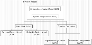
Now we will introduce two types of design models:
Figure 7.2. Design model typology
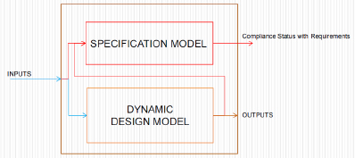
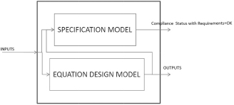
A basic system model of a type of systems is an assembly built by a specification model and a dynamic design model (see Figure 7.3). The specification model carries the requirements assigned to the type of system, whereas the dynamic model is a theoretical model of the type of systems under consideration, as defined in Chapter 4, section 4.4. It is a model that can be executed (“ran”) in the framework of a conceptual simulation (in ones head) or a physical one (on a simulator). When compiled, a system basic model is syntactically true and shall be sufficiently complete to be executed in a simulation environment.
When the system basic model is executed in a simulation, its environment injects inputs (simulation scenarios composed of simulation cases) in the systems model. Outputs are then computed by the design model while the specification model ensures that the inputs and outputs are consistent with the PBRs assigned to the type of systems. If this is not the case, the simulator reports requirement breaches. The simulator thus ensures that (1) the assumptions made about the environment are satisfied (or dissatisfied), (2) the outputs or observable states formulated are consistent (or inconsistent) with the requirements that link the outputs, observable states and inputs, and (3) the requirements focused only on the outputs, or observable states, are satisfied (or dissatisfied).
Figure 7.3. Basic system model. For a color version of this figure, see www.iste.co.uk/micouin/MBSE.zip
In section 7.6.1, we introduce the notion of composite model systems.
7.4. Dynamic design models of a type of systems
We can distinguish between two types of dynamic models: the BDM and the EDM.
7.4.1. Behavioral design model (BDM)
A BDM of a type of systems is a model, which describes the behavior of the targeted type of systems in terms of processes and flows, organized following the architecture chosen by the designer. This constitutes a behavioral architecture4 of the type of systems targeted.
This behavioral architecture ensures the interconnection between the outputs and inputs of the targeted system so that these inputs and outputs are defined in the corresponding specification model. The BDM is linked to its environment (exo-structure) by the intermediary of the inputs and outputs of the specification model, which are interfaces vis-à-vis the exterior world.
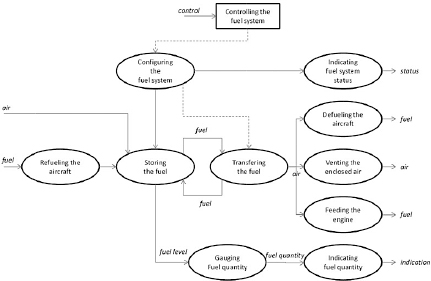
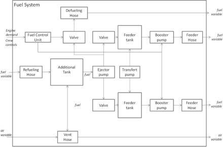
Figure 7.4. Fuel system behavioral design model
In simulation context, the processes composing the behavioral architecture are executed concurrently, in a coordinate manner, in accordance with the synchronizations described (possibly in an erroneous manner) by the designer, and by producing and consuming matter, energy, data and signal flows that interconnect them. These processes can be of three types: discrete, continuous or mixed. When discrete, they produce discrete data or signals from discrete data or signals when the events they expect occur. When continuous, they produce waves of continuous matter, energy or data from continuous inputs. When mixed, they produce discrete outputs (respectively, continuous) from continuous inputs (respectively, discrete).
This is, indeed, a synthesis question (and not an analysis one), as the idea is to create or reuse5 elements (processes and state machines) and a structure (flows), which could allow the model to provide the required outputs as an effect of the inputs (and present state). The objective is, therefore, not to analyze an existing situation but to design6 a new one.
During the design of a type of systems (characterized by the specification model) we can equip it (within the framework of the search for a preferred solution) with different alternatives of behavioral architecture, each one corresponding to a behavioral design model. Among them, there are those that do not satisfy the requirements of the specification model and do not constitute logical solutions to the specification problem. We will see that the verification process described in Chapter 9 enables us to put them aside. The others, which satisfy the requirements of the specification model, are acceptable logical solutions to the specification problem.
Generally, to design a behavioral architecture, we start by giving a description of the modes (for definition, section 2.5) of the type of systems under consideration, which means describing the phases of the functioning cycle of the type of systems, and the transitions that enable us to switch from one mode to the other. Described in design as state machines, the modes and transitions between modes have normally been identified in the specification model, either as requirement activation conditions, or as observable states, because these are the modes that temporally divide the targeted systems intended behavior.
Figure 7.5. System mode model
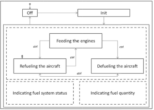
For example, consider a fuel system. It can be at a standstill; in the “off” mode, it produces none of the intended effects. Once started, it passes to an “on” mode after an initializing phase (“init”) during which it undertakes the power-on built-in test (PBIT) of different system components (valves, pumps, gauges and calculators) and displays a status to the crew. Once this initializing phase is successfully carried out, it works according to different modes (three), the main one ensures fuel feeding to the engines at the required pressure. The second ensures refueling, while the third ensures the inverse operation (defueling), which involves emptying the tank, during maintenance, for example. In these three exclusive modes (if the filling of tanks during the flight is excluded by specification), the system, on the one hand, carries out continuous built-in tests (CBITs) and presents a status to the crew, and on the other hand, presents the available quantity of fuel on the basis of fuel gauging process.
The state machine representing the functioning modes of the system enables the description of the systems configuration change command (opening/closing of valves, start up/stop of the pumps, etc.) ensuring the activation of certain processes (feeding) and the inhibition of others (refueling and defueling).
The behavioral architecture organizes chains of processes7 around one or more state machines ensuring the systems main functions in its different modes.
For example, for functional modes of the fuel system mentioned above, we can distinguish:
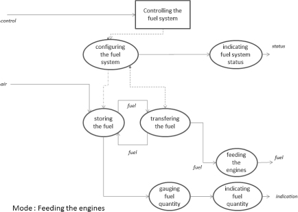
For example, the functional chain “feeding the engines” that enables engine feeding ensures a continuous flow, which goes from the process “storing the fuel” to the process “feeding the engines” passing through the process “transferring the fuel”. This chain is activated by the process “controlling the fuel system” that configures the system in order to activate the chains that work in parallel to “feeding the engines” process, that is to say the chains “indicating the fuel system status” and “indicating fuel quantity” and to inhibit the “refueling” and “defueling” chains.
The “feeding the engines” mode is illustrated below.
Figure 7.6. “Feeding the engines” functional chain
The three functional chains, mentioned above, are synthetically integrated into the behavioral architecture presented in Figure 7.4.
The fuel system is a fluid system with properties, both local (density, pressure, temperature and speed) and global (fuel quantity and gravity center (GC) location) evolving in accordance with the laws of fluid mechanics and thermodynamics (conservation of mass, Newton’s second law and conservation of energy). To each element of the model (process), we can associate a specific theoretical model, that is to say a system of equations linking the inputs and outputs of each process, for example, the laminar or turbulent flow equations in a pipe, across a transfer pump or a control valve, as a function of the considered fluid’s characteristics, compressible/incompressible and viscous/ non-viscous.
7.4.2. Equation-based design models (EDMs)
The prerequisite to carry out a design task is to dispose of a validated specification model of the type of systems to be designed. This means that such a specification model has first been defined and then validated. This notion of validated specification model and the process of validation associated will only be discussed in the following chapter. For the time being, we assume that a specification model is validated if it correctly and completely characterizes the type of systems targeted. In this case, any concrete system conform to the validated specification model is indeed within the set of targeted concrete systems and puts none aside.
For example, for a fuel system, we can start by a basic theoretical model with the aim to validate (this question of specification model validation will be tackled in Chapter 8) the specification model. This minimal design model enables the representation of the intended behavior but, in no way, the effective behavior8 insofar as it ignores the characteristics of the physical architecture of an aircraft fuel system. This physical architecture is the result of trade-off relative to the number of tanks, the capacity, the shape and position of the aircraft in each of them, which are not free variables but take into account the multiple constraints regarding installation, safety and GC location imperatives.
A precise behavioral model of the fuel system will be established once a physical architecture is defined, in order to verify (this question of verification will be tackled in the Chapter 9) that the design solution correctly answers the requirements assigned to the type of systems.
Among the acceptable logical solutions we have considered in the previous section some are minimal in the sense that they introduce a minimal number of processes to interconnect the inputs and outputs of the specification model, while satisfying the requirement of the model. We call EDM a minimal logical solution. This minimal number of necessary processes to interconnect inputs and outputs of the specification model depends on the number of requirements linking the outputs to the inputs or outputs and also to input flow convergences.
An EDM model is a behavioral model that does not take into account any physical architecture or installation constraints and that confines itself to produce an interconnection of inputs and outputs of the specification model by satisfying the requirements of the corresponding specification model. An EDM model is, therefore, an exact executable image of the specification model from which it is deducted. Such EDM equations can be automatically generated from the specification model.
Figure 7.7. Basic system model including an equation design model. For a color version of this figure, see www.iste.co.uk/micouin/MBSE.zip
When a basic system model, constituted of a specification model and an EDM model, is executed during a simulation, the result of the execution being conformed to the specification. It is then possible to ensure that it is correct and complete; in other words, the production of an EDM model is a simple way of validating a specification model (see Chapter 8).
7.5. Derivation and allocation of the system’s behavioral requirements
Once a behavioral architecture is established for a type of systems, we can then consider the way in which the behavioral requirements of the specification model will project themselves on this architecture by determining the intended performance of each process. Some system requirements could then be put aside (such as mass requirements) and will be taken into account at the structural level. However, for those that are taken into account, this projection consists of deriving the system-level requirements into derived requirements assigned to the different components of the behavioral architecture.
For example, if we want to enhance the availability of an aircraft, the time taken to refuel necessarily becomes a property constrained by a requirement. This system-level requirement “at determinate conditions, the time required to fuel up shall be inferior to x” will then derive itself into performance requirements assigned to the processes of fuel storing, fuel transfer and air flushing replaced by fuel in the fuel system.
To ensure the system-level requirement is satisfied, the derived requirements allocated with the processes of the behavioral architecture must have been correctly characterized, and none must have been forgotten. If this is not the case, that is to say the derivation of the system requirement is incorrect or incomplete, there is a major risk that the system requirement is not satisfied in certain circumstances. This is the reason why a process of validation of the specified requirements (to the behavioral architecture processes), with regard to the requirements of the type of systems, is set up and described in Chapter 8 (see section 8.3.4).
7.6. Static design models
We can distinguish between two types of static design models. We will refer to the first model as SDM (structural design model) and the second as RDM (reliability design model). In this chapter, we only take interest in the SDM model, while the RDM model will be considered in Chapter 10.
7.6.1. Composite system model
Previously, we have only considered basic system models, that is to say models constituted of a single system specification model (SSM) and a unique design model (BDM or EDM). These basic models are not enough when we wish to model large and complicated systems.
The SDM is the means by which it becomes possible to represent a system as being constituted of different subsystems that are themselves constituted of items, and so on and so forth, with the needed level of depth. In this way, it is a practical application of the famous “divide and conquer” rule9, which involves, in the world of technological design, subdividing a whole into a network (endo-structure) of parts to be able to tackle and master it. This does not entail a reduction of the whole to its parts as, of course, the endo-structure ensures the emergence of the properties of the whole relatively to the properties of the parts (see section 1.5.4).
Figure 7.8. Composite system model. For a color version of this figure, see www.iste.co.uk/micouin/MBSE.zip
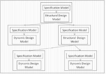
A composite system model is an assembly constituted of specification and design models, and organized according to a tree (tree system). At the root of the tree, we find the node of the type of systems being developed, constituted of its specification model and a structured design model. This SDM refers to subsystem models, which are themselves constituted of a specification and design model. If a subsystem is associated with a non-terminal node in the tree system, then the design model attached to that node is necessarily an SDM. Conversely, if a subsystem model is associated with a terminal node (a leaf) in the tree system, then the design model attached to the node is necessarily a dynamic design model (BDM or EDM).
Following the example of the basic system model, a composite model can also be executed within the framework of a simulation that is conceptual (in ones head) or physical (using a simulator). Compiled, a system composite model is syntactically correct and can be executed in a simulation environment. Particularly, the all the interface compatibility problems, both internal and external (with the environment), are entirely solved during the compilation. Those who know the finalization costs of interface requirement specification (IRS) and interface design description (IDD) will appreciate this.
Figure 7.9. Composite system model. For a color version of this figure, see www.iste.co.uk/micouin/MBSE.zip
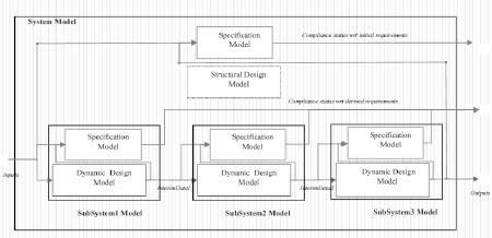
When the system composite model is executed in a simulation, its environment injects inputs (simulation scenarios composed of simulation cases) in the system model. The SDMs connect the inputs and outputs to the subsystem models (not represented in Figure 7.9) up to the terminal nodes. These terminal nodes behave like system basic models, as described in section 7.4. The outputs are formulated by the BDM, while the specification model ensures that the inputs and outputs are in accordance with the PBRs allocated to the type of systems. If this is not the case, the simulator reports the requirements that are breached.
This monitoring process of the consistency of inputs, observable states and outputs with the PBRs is carried out at each level by the corresponding specification models up to the highest level; in other words, each specification level ensures that the inputs and outputs are consistent with the requirements it holds.
We, therefore have, level by level, a complete design model verification process in relation to the corresponding specification models.
7.6.2. Structural design model
An SDM of a type of systems describes the structure of the type of systems being targeted. This description is expressed, in terms of subsystems, hardware, items, etc., and, on the other hand, in terms of link variables (piping variables, cables variables, electric harnesses variables, data links and signal links) organized according to a chosen architecture by the designer, and possibly erroneous. In this way, they constitute a physical architecture of the type of systems targeted.
This physical architecture ensures the interconnection between the outputs and inputs of the type of systems targeted such that these inputs and outputs are defined in the corresponding specification model. The SDM is linked to its environment (exo-structure) by the intermediary of inputs and outputs of the systems model; these are its interfaces with regard to the external world.
Thus, the fuel system we described previously in behavioral terms can be described as a network of tanks, vent hoses, feeders, pumps and sensors linked to a computer. Each of the physical components contributes to the creation of processes identified in the behavioral design model. In this way, the tanks ensure the fuel storing. The apertures ensure fuel filling, piping and pumps ensure the transfer of fuel and air flushing events within the tank or on the contrary its intake, the feeders ensure the tube feeding of engines with fuel, and so on and so forth.
Figure 7.10. Fuel system structural design model
7.6.3. Allocation of BDM components to SDM components
This allocation of elements of a BDM to the elements of an SDM involves the allocation, on the one hand, of processes to processors and, on the other hand, of flows to link variables. We will then, for example, allocate the process of storing to one or more tanks, the processes of transfer to pipes equipped (or not) with pumps.
Two constraints are imposed for these allocations: first, a process cannot be assigned to multiple processors without a preparatory decomposition and, second, each processor must have at least one process assigned to it.
7.7. Derivation and allocation of system requirements
The allocation of behavioral design elements to physical design elements is doubled by the allocation of behavioral requirements carried by behavioral elements to the physical elements supporting them. We could say that the behavioral requirements are inherited by the processors on a physical level.
Then remains the question of structural requirements of the type of systems, which must also be projected onto the SDM. This projection involves the derivation of structural requirements at the system level into derived requirements allocated to the different components of the physical architecture.
For example, if a fuel system must be capable of boarding a given volume of fuel, and if the design introduces a given number of tanks, then this system level structural requirement will be derived into as many structural requirements allocated to the different tanks.
To ensure that the system-level requirement will be satisfied, the derived requirements allocated to the components of the physical architecture must have been correctly characterized and none forgotten. If this is not the case, that is to say if the system requirement derivation is incorrect or incomplete, there is significant risk that the system requirement will not be satisfied under certain conditions. This is the reason why a process validating the specified requirements (to the components of the physical architecture) in relation to the requirements of the type of systems is set up and described in Chapter 8.
As we have explained, this process can be repeated for each building block until encountering either a commercial off-the-shelf (COTS) block or a reusable one, a directly codable block (software) or a directly producible block not requiring any other design task.
Figure 7.11. EIA632 system design process. For a color version of this figure, see www.iste.co.uk/micouin/MBSE.zip
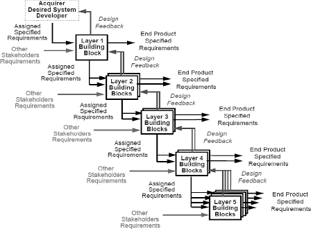
Once each basic component has been produced or supplied, the system integration process will comprise the assembly of different elements of the system in a pre established order and the verification of the conformity of successive assemblies to the intermediary specifications up to the specifications of the system itself. This is what Figure 7.11 illustrates, inspired from the EIA 632. This verification process will be described in Chapter 9.
7.8. The end of the design process and the realization
The design process ends once all the lowest level blocks have been identified and the specification models of these blocks are validated. They do not require ulterior decomposition because they are sufficiently simple components to be directly produced. This can especially be the case for software components, which can be directly coded, and electronic components, which can be directly synthesized.
A second ending condition lies in the fact that the specification of the block has been handed over to a supplier who is in charge of developing and producing it. This is what we call an acquired block.
A third ending condition to the design process lies in the fact that the physical realization of the specified block already exists and these physical realizations are consistent with the block requirements. This is block we call a COTS.
1EIA632, page 64.
2ED791/ARP4754A, page 7.
3Scott Jackson who speaks, in a very suggestive way, of “derived requirement harmonics” in systems engineering for commercial aircraft, Ashgate Publishing Company, p. 43, 1997.
4In reference to Gero’s FBS framework, we prefer the expression “behavioral architecture” to the generally used expression “functional architecture”.
5For example, exterior models available in existing catalogs or produced during preliminary studies (see section 11.1).
6In accordance with Descartes’ third rule of method, “the third was to direct my thoughts in an orderly manner, by starting with the simplest and most easily known objects in order to move up gradually to knowledge of the most complex” Discourse on Method, René Descartes, Part 2, page 9, translated by Jonathan Bennett, 2007, http://www.earlymoderntexts.com/.
7These are often called “functional chains”.
8For the distinction between intended behavior and effective behavior, see Chapter 2 (section 2.3).
9“This is the second rule of Descartes method”. Disourse on Method, René Descartes, Part 2, page 9, translated by Jonathan Bennett, 2007, http://www.earlymoderntexts.com/.