
1
Graphite and Graphene Nanoplatelets (GNP) Filled Polymer Matrix Nanocomposites
Marc PONÇOT, Adrien LETOFFE, Stéphane CUYNET, Sébastien FONTANA and Lucie SPEYER
Institut Jean Lamour, University of Lorraine, Nancy, France
1.1. General information on graphene
1.1.1. Definition and structure
Graphene is a plane of carbon atoms in sp2 hybridization. It is the basic constituent of graphite, carbon nanotubes and fullerenes. Figure 1.1 shows a graphene plane.
Graphene can present some structural defects, although its low dimensionality reduces the number of possible imperfections. For instance, the graphene plane may not be strictly composed of hexagons of carbon atoms: these are Stone–Wales defects, where four hexagons are transformed into two pentagons and two heptagons when one of the bonds rotates. Single and double gaps can appear, as well as dislocations, atoms and impurities of substitution. These defects have a strong influence on the physical properties of graphene. In addition, some defects generate dangling bonds that increase the chemical reactivity of graphene (Banhart et al. 2011).
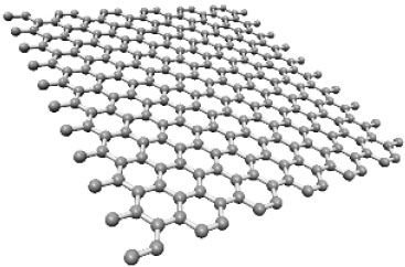
Figure 1.1. Representation of a graphene plane
1.1.2. Structures associated with graphene
As will be discussed later in this chapter, a single graphene plane is difficult to obtain and synthesis methods most often result in the stacking of multiple planes, often referred to in the literature as graphene itself. In fact, a specific terminology for carbonaceous materials with a two-dimensional character has been established (Bianco et al. 2013) and the following structures should be distinguished from the single graphene plane:
- – double-wall or triple-wall graphene: structure in free suspension or resting on a substrate, composed of a stack of two or three graphene planes of extended lateral dimension;
- – few-layer graphene (FLG): structure in free suspension or resting on a substrate for a stack of two to five planes;
- – multi-layer graphene (MLG): structure in free suspension or resting on a substrate for a stack of six to 10 planes;
- – graphite nanosheets: two-dimensional graphitic materials with one dimension not exceeding 100 nm;
- – nanoribbon graphene: graphene plane as defined above, with lateral dimensions not exceeding 100 nm and 10 nm, respectively;
- – graphenic carbonaceous materials: include all of the carbonaceous materials made up of sp2-hybridized atoms, like the structures defined above, or the disordered carbons (carbon blacks, activated carbons) and graphite.
1.1.3. Graphene properties
The calculated and measured properties of graphene are unique and remarkable, which explains the interest of the scientific community. Wallace (1947) showed the particular electronic structure of graphene. Thus, graphene is considered as a zero-gap semiconductor. The mobility of charge carriers is high and has been measured up to 230,000 m2·V–1·s–1 (Bolotin et al. 2008). This value corresponds to the highest value for a semiconductor. Its thermal conductivity is also remarkable. It reaches 5,300 W·m–1 ·K–1 (Rutter et al. 2007), which corresponds to the highest value for a material. In comparison, diamond, which is well known for its ability to evacuate heat, has a thermal conductivity of only 2,000 W·m–1·K–1. Its network of sp2-hybridization atoms gives graphene a unique set of mechanical properties. The combination of a hardness equivalent to that of diamond, close to 1 TPa, a very high flexural strength, a high specific stress at break of 48,000 kN·m·kg–1 and its elongation at break of 25% makes it unique (Lee et al. 2008; Zhu et al. 2010). In comparison, steel has a specific stress at break of 154 kN·m·kg–1 (Zhu et al. 2010). Graphene has a transparency of 97.7% in the visible spectrum (Rutter et al. 2007; Zhu et al. 2010). Graphene is considered to be the most impermeable material in the world. This is due to the combination of its sp2-hybridization carbon atom lattice with high electron density in its aromatic rings and its structure (covalent bonds and rupture stress) (Berry 2013). Another important property of graphene is that its theoretical specific surface area is 2,630 m2·g–1 (Ferrari et al. 2015), which is very high for a carbonaceous material.
1.2. Graphene preparation methods
Graphene is an amazing material because of the combination of exceptional properties conferred by its two-dimensional character and sp2-hybridization lattice of carbon atoms. The properties are particularly noticeable in the case of a single plane of free single-crystal graphene. Many works have been dedicated to graphene synthesis since the research by Novoselov and Geim (2004). Several so-called major synthesis methods have been developed and allow very different samples to be obtained according to several criteria:
- – the structural quality and chemical purity of the sample;
- – the presentation of the sample: graphene planes on metallic substrate, SiC or other, or dispersion;
- – the cost price and the industrializable nature of the method.
Figure 1.2 shows the materials obtained by the synthesis methods described in this chapter, according to their structural quality and their estimated cost for industrial production.
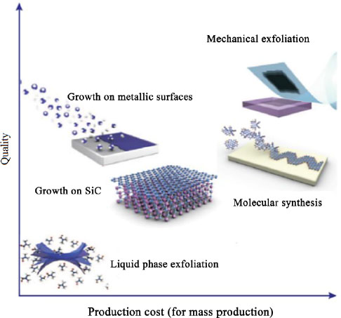
Figure 1.2. Quality and industrial cost of graphene samples obtained by different synthesis techniques (Novoselov et al. 2012). For a color version of this figure, see www.iste.co.uk/bai/nanocomposites.zip
Mechanical exfoliation produces an excellent structural quality but, although very simple in principle, would generate too high a manufacturing cost. Liquidphase exfoliation, although based on the same principle, provides graphene dispersions of lower quality, but it is much easier to obtain large quantities of material. The supported growth techniques, which will not be detailed in this chapter, are expensive techniques (energy cost, price of substrates and silicon carbide wafers, reaction chambers), but the material is of high quality, and some techniques make it possible to obtain very large surface areas (Bae et al. 2010). In graphite, the cohesion of the crystal along the axis ![]() is ensured by Van der Waals bonds. The basic principle of exfoliation techniques is to break these bonds, by the so-called dry method or in liquid phase, in order to obtain graphene. It is also possible to exfoliate other graphite-based materials, such as intercalation compounds and graphite oxide (GO).
is ensured by Van der Waals bonds. The basic principle of exfoliation techniques is to break these bonds, by the so-called dry method or in liquid phase, in order to obtain graphene. It is also possible to exfoliate other graphite-based materials, such as intercalation compounds and graphite oxide (GO).
1.2.1. Graphite exfoliation
1.2.1.1. Dry exfoliation
Mechanical exfoliation is the synthesis technique made famous by Novoselov and Geim (2004). The principle is very simple and consists of applying adhesive tape on graphite (typically pyrolytic graphite because of its superior crystalline quality), peeling off the tape by isolating a certain thickness of graphene planes, and repeating the operation on the film thus obtained until the thinnest possible thickness is reached (Novoselov et al. 2004). The material is then usually transferred to a SiO2/Si substrate to allow for the selection of the single walls by way of characterization techniques, such as optical microscopy. To date, mechanical exfoliation remains the technique that enables the best electronic and structural quality to be obtained. However, it is not suitable for industrial production: its main application remains basic research and the development of prototypes for various applications (Novoselov et al. 2012). Other dry exfoliation techniques have been developed, motivated by the crystalline quality of graphene obtained by mechanical exfoliation and in attempts to solve the problem of large-scale production. Laser ablation of graphite (Dhar et al. 2011) or anodic exfoliation (Shukla et al. 2009) have been performed and also yield high-quality material.
1.2.1.2. Liquid-phase exfoliation by ultrasound
Liquid-phase exfoliation of graphite is based on graphite dispersion in solvent and on the transition from dispersion to ultrasounds. Due to the hydrodynamic forces, the ultrasounds will generate a phenomenon of cavitation, namely the formation of bubbles. These bubbles will be able to break the Van der Waals bonds between the graphene planes, and the solvent must be able to stabilize the planes in suspension to prevent their reaggregation. The fundamental characteristic of the solvent to be considered in this perspective is the surface tension. Indeed, a solvent with adapted surface tension will be able to minimize the interfacial tension between the graphene sheets and the solvent molecules, and thus prevent their reaggregation. The ideal surface tension is 40–50 mJ·m–2. Graphite exfoliation is thus carried out in solvents such as N-methylpyrrolidone (NMP) or dimethylformamide (DMF). A centrifugation step needs to be added to remove the thickest particles (Hernandez et al. 2008). This process allows dispersions of micrometer-sized particles to be obtained, generally less than 5 planes thick, with a final content of 1 wt% of single-walled graphene. A very long sonication time (more than 300 h) makes it possible to obtain concentrations of the order of 1 mg·mL–1 with a single-walled yield of 4 wt%, but ultrasound tends to fracture the sheets and reduce their size (Khan et al. 2008). Solvents such as NMP or DMF are toxic and their high boiling point (202°C for NMP and 153°C for DMF) is problematic as they evaporate slowly when the dispersion is deposited on a substrate (e.g. for the purpose of producing graphene film), which favors particle reaggregation. In contrast, isopropanol and chloroform, which have low boiling points (respectively, 82°C and 62°C), provide less concentrated graphene dispersions than NMP and DMF, possessing about 1 wt% single-layered graphene, but react less easily during a deposition process (O’Neill et al. 2011). Water does not present the surface tension required to stabilize graphene planes. Still, the addition of surfactants can enable the exfoliation of graphite in aqueous media, such as sodium dodecylbenzene sulfonate (SDBS) (Lotyal et al. 2009) and sodium cholate (Green and Hensen 2009). When graphene planes are dispersed in an aqueous medium, the hydrophobic part of the surfactant associates itself with the graphene planes and the hydrophilic part points toward the water. The whole forms a structure similar to a micelle that thus stabilizes the graphene plane. Similar to organic solvent exfoliation, dispersion by means of surfactants provides micrometer-sized particles consisting of a few graphene planes (Lotyal et al. 2009; Notley 2012). The continuous addition of surfactant during exfoliation makes it possible to achieve concentrations of 15 mg·mL–1, and controlled separation of particles according to their thickness is possible using the density gradient centrifugation technique (Green and Hensen 2009; Notley 2012). The graphite exfoliation process, in either organic or aqueous media, does not introduce structural defects into the graphene planes. Dispersions are stable for several weeks to months.
1.2.1.3. Graphite exfoliation and functionalization by plasma process in one step
1.2.1.3.1. Plasma by dry-process
Environmentally friendly and economically viable synthesis processes for obtaining pure single-walled graphene with excellent physicochemical properties remain to be discovered. Nevertheless, recent research in the field of plasma physics seems promising (Dey et al. 2016; Levchenko et al. 2016; Giorcelli et al. 2018).
The dry plasma processes used for the preparation or the functionalization of graphene are varied. First, they are differentiated according to the gas pressure, ranging from low pressure processes (a few Pa to 100 Pa) widely known in the literature (Malesevic et al. 2008; Brault et al. 2013; Tsai et al. 2014; Yue et al. 2014) to atmospheric pressure processes in strong development (Subrahmanyam et al. 2009). Low-pressure plasma processes are strongly local thermodynamic non-equilibrium processes with high electron temperatures of up to a few tens of electron volts and a low ionization degree (Samukawa et al. 2012). Plasmas at atmospheric pressure, on the other hand, can exhibit a high degree of ionization, but low electron temperatures (Anders et al. 2009). The pressure difference between the two processes plays a major role in the physical and chemical action that the plasma will have on the etching material. Second, dry processes are differentiated according to the generated plasma regime, which can range from continuous discharges to pulsed discharges and even very high frequency discharges at the electron cyclotron resonance. Plasma arc and jet processes have been mentioned in the literature from the last few years (Wu et al. 2010a; Kim and Suh 2014), mainly because of their ease of implementation and the large quantities of material that can be processed.
1.2.1.3.2. Liquid-phase plasma
Depending on the process, plasma physics is of real interest to prepare or functionalize graphene in the dry process. It is thus possible, for example, to produce liquid-phase graphene nanosheets from asphalt by plasma (Li et al. 2013). On the other hand, the possibility of carrying out both production and functionalization in a single step by means of plasma process requires the removal of scientific and technical barriers, in particular by dissociating purely physical processes from reaction processes. Within this perspective, a first milestone is being achieved at the Institut Jean Lamour in Nancy, by proposing an alternative process based on plasma exfoliation and functionalization of carbon charges in aqueous phase and at atmospheric pressure. In addition to the objective of combining the production of graphene and its functionalization, this new aqueous phase process should also make it possible to avoid the effects of agglomeration and curling of graphene sheets, which are found experimentally and systematically after a synthesis process, before the one enabling the functionalization of graphene. A diagram of the experimental device is proposed in Figure 1.3.
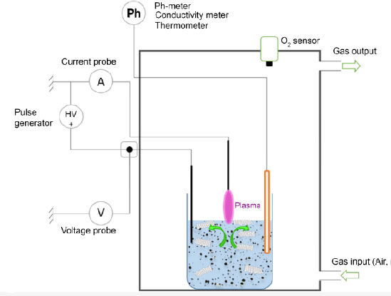
Figure 1.3. Schematic of the plasma device allowing both the exfoliation and the functionalization of graphitic charges in solution. For a color version of this figure, see www.iste.co.uk/bai/nanocomposites.zip
This process operates in the nano- and microsecond-pulsed arc plasma regime on the surface of an aqueous solution loaded with pure graphite particles. A voltage generator coupled to a nanosecond voltage chopper provides a square-wave electrical power signal over the range 0–30 kV and 0–100 kHz, with a pulse duration ranging from 10 to 2000 ns. An electrode immersed in the liquid is connected to the high voltage, so that potential changes are transferred to the surface of the aqueous phase. The upper electrode of the same nature is connected to the ground of the system. The plasma arc discharge is then located between the surface of the solution and the upper electrode. The initiation of the plasma, which is called breakdown, occurs under experimental conditions verifying Paschen’s laws, that is to say when the product between the gas pressure and the distance between the electrodes minimizes the breakdown voltage of the gas. The interest of the high-voltage pulse regime is to promote the exfoliation process of graphite by the ignition of shock waves during plasma breakdown in the air at atmospheric pressure: the carbon planes of the carbon charges located on the surface of the liquid can then undergo a mechanical release. Studies of propagation waves originating from gas bubble formation in a similar case of discharge in liquids indicate that pressures above 107 Pa can be reached locally (Hamdan et al. 2013a). The other advantage of this discharge regime is that it allows for high energy plasma functionalization while having a low energy process, with an average power between 10 and 120 W, depending on the discharge conditions. By imposing only the gas breakdown voltage, it is possible to evolve the process to reach currents of a few amperes. To this end, the aqueous solution will undergo radical changes at the level of its initial intrinsic properties, particularly at its composition level, which will modify its pH and conductivity. This change in liquid composition is due to plasma–liquid interactions, and more specifically to the progressive solvation of plasma-derived species at the liquid surface, such as electrons, ions, and other radicals or energetic species (Lukes et al. 2014; Bruggeman et al. 2016). The evolution in the composition of the medium, its acidification and its progressive rise in temperature are all variable parameters that also promote graphite exfoliation processes on the surface and in the volume of the liquid, as well as reactional mechanisms to functionalize the graphene planes.
1.2.2. Graphite-derived compounds exfoliation
1.2.2.1. Graphite intercalation compounds exfoliation
1.2.2.1.1. Graphite intercalation compounds
Due to its lamellar structure, graphite can accommodate chemical species, called inserts, in its interplanar spaces to give graphite intercalation compounds. Intercalation is a redox reaction that is accompanied by a charge transfer between the graphene planes and the insert; graphite, being amphoteric, can react with electron acceptors and donors. In the well-known example of the KC8 compound and of alkali metal intercalation in general, the metal acts as an electron donor. It acquires a positive partial charge, while the graphene planes have a negative partial charge.
1.2.2.1.2. Graphite intercalation compounds thermal exfoliation
Thermal exfoliation is most often carried out using intercalation compounds obtained with nitric acid and sulfuric acid. When a violent thermal shock is applied to the intercalation compound, the insert does not have time to diffuse out of the structure and vaporizes directly in the core of the material, causing the graphene planes to spread apart along the axis ![]() , due to strong pressure, and a strong increase in volume. The material thus obtained is called exfoliated graphite. It is not very dense and presents an accordion-like structure (Figure 1.4) (Furdin 1998; Inagaki et al. 2004; Afanasov et al. 2010).
, due to strong pressure, and a strong increase in volume. The material thus obtained is called exfoliated graphite. It is not very dense and presents an accordion-like structure (Figure 1.4) (Furdin 1998; Inagaki et al. 2004; Afanasov et al. 2010).
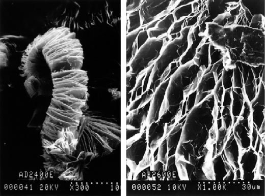
Figure 1.4. SEM micrographs at different magnifications of exfoliated graphite developed at the Jean Lamour Institute
Exfoliated graphite can also undergo ultrasonication and grinding steps to yield a material called flat micron graphite (FGM), consisting of single-crystal particles tens of micrometers wide and a few dozen graphene planes thick (Furdin et al. 1991).
1.2.2.1.3. Liquid phase exfoliation of graphite intercalation compounds
The dispersion of a graphite intercalation compound, usually based on alkali metals, in a polar solvent leads to its exfoliation due to charge separation. Electrostatic interactions stabilize the negatively charged graphene planes in suspension. The most widely used compound is KC8 (Catheline et al. 2011, 2012). K(THF)C24 exfoliation has also been reported (Vallés et al. 2008). The exfoliations were initially performed in high-boiling solvents such as NMP but, as with graphite exfoliation, these solvents can be replaced by more easily removed solvents such as tetrahydrofuran (THF). The dispersions are stirred and centrifuged and the resulting particles, of micro-metric size, consist of a stack of one to a few graphene planes (Vallés et al. 2008; Catheline et al. 2011, 2012). The concentrations obtained are of the same order as those of dispersions obtained directly from graphite. Upon the deposition of the dispersions on a substrate, the exposure of the graphene sheets to air returns them to their 0-oxidation state and leads the Kδ+ counterions to oxidize. The oxides are easily removed through washing. The main drawback of this method for obtaining graphene is the extreme sensitivity of the alkali metals and graphite intercalation compounds to air, which must be handled under an inert atmosphere.
1.2.2.2. GO exfoliation
1.2.2.2.1. Graphite oxide
GO is a compound that has been known for many years. This is graphite that has been treated in an oxidizing acid medium. Several historical methods of GO synthesis exist, such as the Hummers method or the Staudenmaier method. The Hummers method consists of treating graphite with sulfuric acid, potassium permanganate and sodium nitrate (Hummers and Offeman 1958). GO, a light-yellow solid, is thus made up of a stack of “graphene” planes carrying various types of oxygenated functions. The oxygenated functions that a carbonaceous material can exhibit are listed in Figure 1.5.
The structure of GO depends on the oxidative treatment (Botas et al. 2013) and the crystalline quality of the starting graphite (Botas et al. 2012). Therefore, it is difficult to establish a typical structure for this type of material and several models have been established (Dreyer et al. 2010). GO mostly contains phenol, carbonyl, carboxyl, ether and lactone functions (Figure 1.5) (Gao et al. 2009). These functions have the effect of doubling the interplanar distance of the compound compared to graphite (Schniepp et al. 2006), and oxidative treatment also leads to the degradation of the sp2 lattice.
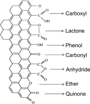
Figure 1.5. Oxygenated functions carried by carbonaceous materials (Figueiredo et al. 1999)
1.2.2.2.2. GO thermal exfoliation
This technique experimented by Boehm et al. (1962) lead to the first probable observation of graphene and has been recently reutilized with the works on graphene synthesis. When GO is heated rapidly to a temperature of about 1,000°C, the organic functions decompose into CO and CO2. The pressure thus generated is enough to exfoliate the graphene planes. A black solid composed of crumpled graphene sheets is obtained and after dispersion in NMP or DMF, single-walled graphene with micrometric lateral dimensions can be isolated (Schniepp et al. 2006; McAllister et al. 2007). Oxidative treatment disrupts the sp2 lattice of the sheets and thus compromises their properties. Although thermal decomposition of the functions removes much of the oxygen, an ideal graphene structure cannot be restored. Violent heating leads to the additional formation of carbonyl and epoxy groupings, which are thermodynamically very stable and therefore difficult to remove. Furthermore, the removal of the functions leaves sp3-hybridized atoms and atomic gaps within the planes (see Figure 1.6).
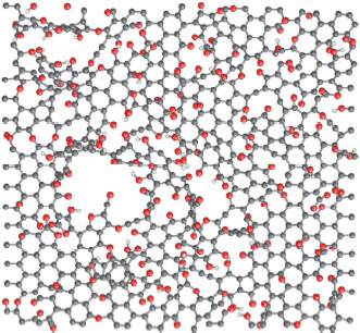
Figure 1.6. Structure of graphene oxide after thermal exfoliation (carbon atoms in gray, oxygen in red and hydrogen in white) (Bagri et al. 2010). For a color version of this figure, see www.iste.co.uk/bai/nanocomposites.zip
1.2.2.2.3. Liquid-phase exfoliation of GO
The oxygenated functions grafted onto the GO planes make them hydrophilic, unlike a purely carbonaceous surface, which is highly hydrophobic. Thus, a simple dispersion in water is sufficient to exfoliate the GO and stabilize particles mostly composed of a single plane (Gomez-Navarro et al. 2007; Stankovich et al. 2007). GO also exfoliates in organic media (Traina and Pegoretti 2012). The material thus obtained is called graphene oxide. It carries the same functions as the parent GO and the carbon/oxygen atomic ratio is between 2 and 3 (Stankovich et al. 2007; Paredes et al. 2008). The characterization of the transport properties indicates a strong degradation of the sp2 lattice: graphene oxide is a quasi-insulating material (Gomez-Navarro et al. 2007). In order to restore the properties of graphene oxide, a reduction step is implemented. The most commonly used reducer is hydrazine N2H4. This treatment allows a good part of the oxygen to be eliminated (the carbon/oxygen atomic ratio can rise up to 10) and significantly improves the conduction properties (Gomez-Navarro et al. 2007; Stankovich et al. 2007). However, the charge carrier mobility is 30 cm2·V–1·s–1, which still remains much lower than the results obtained with “pure” graphene (Gomez-Navarro et al. 2007). Moreover, as the functionalization is weaker after reduction, the particles become less hydrophilic, tend to reaggregate in aqueous medium and are very difficult to redisperse (Stankovich et al. 2007). Since hydrazine is toxic, several studies have been conducted to replace it. Non-hazardous compounds such as ascorbic acid (vitamin C) are equally effective (Fernandez-Merino et al. 2010). Furthermore, since oxygenated functions are more or less thermally stable, the reduction of graphene oxide can be achieved by thermal reduction at temperatures on the order of 1,000°C (Becerril et al. 2008; Bagri et al. 2010). It has been shown that thermal reduction could lead, at high temperatures, to the formation of particularly stable oxygenated groups that are difficult to eliminate, but it yields good or even better results than chemical reduction, especially with respect to the restoration of the sp2-hybridization lattice and transport properties.
1.3. Methods of dispersion of carbon nanofillers in a polymer matrix
The method of dispersion of nanofillers within a polymer matrix is as impactful on the final properties of the composite as the choice of the filler and its potential chemical treatment: it can strongly modify the different percolation thresholds. Numerous methods have been developed according to the polymer matrix used and the targeted properties. These methods, for the most part, are divided into three categories: preparations by in situ polymerization, solution mixing and melt mixing. Moreover, each of these methods is divided into those known as non-covalent, with a nanofiller simply dispersed in the matrix, and those known as covalent, allowing the creation of chemical bonds between the filler and the matrix.
1.3.1. In situ polymerization
In situ polymerization dispersion is a method of nano-composite preparation that can be adapted to a wide range of thermoplastic matrices, such as polyolefins (Fim et al. 2010), polyamides (PAs) (Pan et al. 2000), polystyrenes (PSs) (Chen et al. 2003b), and polymethyl methacrylate (PMMA) (Chen et al. 2003a), but also within thermosetting matrices such as epoxy resins (Miller et al. 2010; Kernina et al. 2019). This method allows for the production of composites from matrices that cannot be used in melt mixing (thermal instability) or dispersed in solution (insoluble polymer). The method is classically carried out in two stages: the first being the mixing of one or more monomers, in powder form or dispersed in a solvent, with the nanofiller, to obtain a homogeneous mixture, then the polymerization of the monomer(s) is carried out to obtain the final nanocomposite. For example, Cromer et al. (2015) performed in situ polymerization of a polypropylene (PP) in the presence of exfoliated graphene fillers. The materials produced by in situ polymerization show better mechanical properties than an equivalent nanocomposite produced by melt mixing, with notably higher elongation at break. Their work highlights the impact that nanofillers can have on polymerization, and the need to modify the conditions in order to maintain the efficient polymerization reaction.
Pol’shchikov et al. (2013) compared two nanocomposites obtained by in situ polymerization via two methods. The nanofillers employed were GNPs produced from oxidized graphite according to the previously mentioned Hummers method. With their first method, the nanofiller, after being heated to 200°C, is placed inside the reactor with dissolved propylene and the metallocene catalyst. With the second method, the nanofiller is first dispersed in toluene and ultrasonicated for 10 or 30 minutes. It is then added to the reactor with propylene and metallocene catalyst. For both methods, the resulting materials were rinsed with a mixture of ethanol and HCl, then washed with alcohol and dried. In both cases, infrared spectroscopy analysis showed that the stereoregularity of the obtained iPP was not influenced by the addition of the nanofiller, but that the use of ultrasound has greatly influenced the dispersion of carbon within the matrix. The two ranges of materials show a close percolation threshold (between 2 and 3 vol%), but the ultrasonically treated materials show higher electrical conductivity and a greater impact of the filler on the mechanical properties with better elongation at break and on the crystallization of the material, with a higher crystallization temperature (Pol’shchikov et al. 2013).
As introduced earlier, it is possible to produce covalent bonds between the nanofiller and the matrix during the polymerization. For example, Huang et al. (2010) performed in situ polymerization of an oxidized PP/graphene nanocomposite with the creation of covalent bonds. The elaboration starts with the preparation of nanofillers via the use of Grignard reagents, in order to obtain a GO nanofiller grafted with Ziegler–Natta catalysts, called TiCl4/(BuMgCl/GO). As presented in Figure 1.7, the obtained filler is then employed for the production of a PP/GO nanocomposite by in situ polymerization. The final nanocomposite shows covalent bonds between the PP polymer matrix and the GO filler. These covalent bonds allow the possible incompatibility between the nanofiller to be bypassed, here polar (GO), and the non-polar polymer matrix, PP, resulting in a better exfoliationand dispersion of the nanofiller. In the work by Huang et al. (2010), an excellent exfoliation of GO fillers is achieved.
It should be noted that the in situ polymerization method can produce a very high level of exfoliation of the carbon planes, especially for intercalated graphite (ICG) or expanded graphite (EG) fillers, by the intercalation of monomer molecules between the carbon planes, and their separation during the polymerization step. This method, which can be called intercalation polymerization, is very similar to the methods used for polymer/clay composites (Ray et al. 2003). The graphene planes are intercalated with monomer molecules in addition to alkali metals in the case of ICGs, or between the accordion planes of EGs (Shioyama et al. 2000). In the case of GO fillers, the distance between oxidized graphene planes, between 0.6 and 0.8 nm, compared to 0.34 nm for a graphite filler, also allows the intercalation of monomer molecules or polymer chains (Jang et al. 2008), particularly in the case of polar polymers such as polyvynilalcohol (PVA) (Ma et al. 2016). The major problem with in situ polymerization development is the complexity of its implementation, but also its high energy consumption, which makes it difficult to apply to high-volume production (Potts et al. 2011; Gulrez et al. 2013).
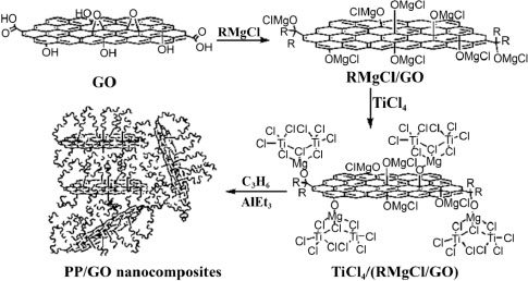
Figure 1.7. Production of PP/GO nanocomposite by in situ Ziegler–Natta polymerization (Huang et al. 2010)
1.3.2. Intercalation in solution
Solution intercalation processing, like in situ polymerization, provides excellent results for dispersion and exfoliation of a carbon filler within a polymer matrix. The method is applicable to any matrix that can be put into solution in a solvent, such as polyethylenes (PE) (Pang et al. 2010) or PS (Fang et al. 2009). The method simply consists of dispersing the polymer and the nanofiller within the same solvent, and taking advantage of the low viscosity of the mixture to ensure its homogeneity before extracting the solvent. The method is particularly suitable for developing nanocomposites employing an oxidized graphite nanofiller and a water-soluble polymer matrix. Indeed, due to their functionalizations, GO fillers are easily dispersible in water, often by a sonication operation enabling their exfoliation. For instance, Salavagione et al. (2009) produced a PVA/reduced oxidized graphite nanocomposite (RGO often obtained by adding hydrazine) by solution intercalation. The carbon filler employed is an oxidized graphite (GO) developed by the Hummers method. The same method without the reduction step is also performed for the production of PVA/graphite and reduced PVA/oxidized graphite, in order to compare their exfoliation state. Thus, the graphite-filled composites show significant agglomerations in the matrix, while GO and RGO composites show better exfoliation of their fillers, especially for PVA/RGO, with an electrical percolation threshold at 1wt%. The choice of the filler influences the quality of the exfoliation and the dispersion of the final composite, and shows the necessity to adapt the solvent. The importance of the initial dispersion of the filler by ultrasound can also be seen in this case. In an optimal filler/matrix/solvent configuration, it is thus possible to obtain excellent dispersion results, allowing the percolation threshold of the produced nanocomposite to decrease. In some cases it is possible to obtain a percolation threshold lower than 0.5 wt%, as shown by Pang et al. (2010). In their work, a nanocomposite is developed from a high-density polyethylene (HDPE) and an EG nanofiller produced by the Hummers method. Carbon-coated HDPE particles are obtained and shaped by hot pressing. The method of development allows the creation of a percolated lattice, even at low carbon levels during forming. This result is also visible with the evolution of the conductivity represented in Figure 1.8, with an important increase between the materials at 0.005 vol% and 0.076 vol%, and a percolation threshold estimated at 0.070 vol%.
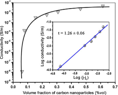
Figure 1.8. Evolution of electrical conductivity as a function of GNP volume fraction of an HDPE matrix nanocomposite (Pang et al. 2010). For a color version of this figure, see www.iste.co.uk/bai/nanocomposites.zip
The main limitation of the solution intercalation method comes from the limited number of solvents that can be used, but also from the polymer matrix, which must have a high solubility in order to enable a homogeneous mixing. Moreover, in the case of certain polymers which are difficult to solubilize, such as PP, the use of polar solvents such as xylene is necessary. The intercalation method in solution then requires the evaporation of large quantities of organic solvent, which makes the method not environmentally friendly and hardly adaptable to the industrial production of nanocomposites (Bafana et al. 2017).
1.3.3. Melt mixing
Melt mixing is the most widespread method for the preparation of nanocomposites because of its ease of implementation and the large quantity of materials that can be produced. Moreover, it is the most interesting method from an ecological point of view because it does not involve solvents. Therefore, melt mixing is mainly employed by the industrial sector. There are two main technological routes for this production method: by internal mixing, where the matrix is melted before the addition of the nanofiller, and by extrusion, where the filler can be introduced either at the extrusion inlet with the polymer pellets or during the extrusion process. Because of the great adaptability of an extruder by changing the profile of the conveying screws and the possibility of varying the temperature during mixing, extrusion is the most often favored technology.
Similar to the solution intercalation method which can only be applied to matrices that are soluble in a solvent, the melt mixing method can only be used for matrices that are not too sensitive to thermal degradation. Despite this limitation, it is applicable to many matrices commonly used in industry, such as PP (Kalaitzidou et al. 2007a), PET (Zhang et al. 2010), PA (Canales et al. 2015) and PS (Oxfall et al. 2013). A major shortcoming of this method is a generally higher percolation threshold than with previous methods, mainly due to the fact that the mixture viscosity remains high.
Many authors have proposed methods to improve the dispersion of the filler within the matrix in order to improve its electrical and mechanical properties. The first development parameter that can be easily modified is the mixing speed by screw rotation. Khanam et al. (2016) highlight its importance in the development of a low-density polyethylene/GNP composite. Their results show an improvement in the mechanical properties and electrical conductivity of the nanocomposites, with increasing screw rotation speed due to better dispersion of the nanofiller. However, the authors note that the improvement of the properties is limited when high carbon concentrations are used. Another interesting approach is, as in the case of in situ polymerization or solution intercalation, the use of ultrasound during the production to allow for a better exfoliation and dispersion of the nanofillers. These can either be used during the preparation of the production to ensure the homogeneous mixing of the polymer in powder form with the filler, or directly during the extrusion mixing. He et al. (2018) produced nanocomposites with a GNP mass fraction between 9 and 15 wt% by a single screw extruder coupled with an ultrasonic system, as shown in Figure 1.9. Different configurations were investigated by varying the rotation speed of the extruder and the applied power of the ultrasonic treatment.
These same authors first note an increase in the number and size of the aggregates within the matrix with the increase in carbon concentration. Following the use of ultrasound, an improvement of the dispersion is observed for each concentration. Another important observation is that increasing the power of the ultrasonic treatment makes it possible to reach a better dispersion and even enables the exfoliation of the filler from a certain power, 300 W in the case of their work. The electrical conductivity of the different materials is improved with the increase in the carbon concentration, but also in the case of materials with and without ultrasound treatment. A last interesting result observed by the authors is that an increase in the extruder rotation speed during the ultrasonic treatment decreases the filler dispersion.
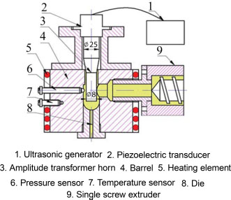
Figure 1.9. Schematic of the setup for extrusion-based production using ultrasound (He et al. 2018). For a color version of this figure, see www.iste.co.uk/bai/nanocomposites.zip
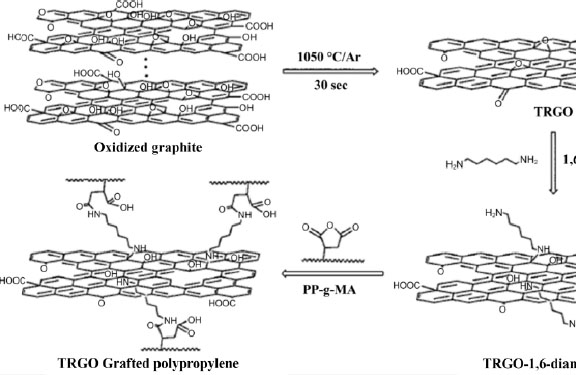
Figure 1.10. Preparation of TRGO-grafted polypropylene (Hsiao et al. 2010)
A classical variation of the melt mixing preparation makes use of an intermediate step called masterbatch. The method consists of achieving a first polymer/filler mixture with high concentrations (which can exceed 75wt% in nanofiller), then diluting this masterbatch during extrusion to reach the targeted filler concentration. The masterbatch method is indicated for the realization of nanocomposites based on a matrix with a low compatibility with the nanofiller, such as PP, because it is possible to use a derivative close to the matrix during the production of the mixture with high carbon content. For example, Rosehr et al. (2018) employ an atactic PP (aPP) in their works to facilitate the dispersion of their graphite nanofillers within an iPP matrix. Two mixtures were produced by solution mixing in 50 and 80 wt% carbon toluene, respectively. The mixture, after drying, was added to an iPP matrix by extrusion. IPP/graphite melt mixing, without a masterbatch step, was performed in order to study the impact of the aPP on the dispersion. The authors observe a decrease in the crystallization of the nanocomposite with the increase of the fraction of aPP in the mixture, but especially an improvement of the dispersion of the nanofiller, with the disappearance of the large agglomerates present in the nanocomposite without masterbatch. The materials produced from the 50 wt% carbon masterbatch show excellent filler/matrix compatibility due to the aPP remaining on the surface of the fillers. In addition, it limits the reagglomeration of the carbon planes.
In the case of PP, another agent commonly used to improve nanofiller compatibility is maleic anhydride (MAH). MAH is a chemical group that can be grafted to the macromolecular chain of numerous polymers such as PP to provide new functionalities. In the case of carbon nanofiller dispersion, the polarity of the MAH grouping allows for improved dispersion, whether the blends are obtained in solution (Li et al. 2018), by melt mixing (Shanks and Cerezo 2012), or via a masterbatch (Li et al. 2017). Similar work was conducted on polyethylene by Shen et al. (2005). The addition of MAH to the nanocomposite elaboration opens up another elaboration possibility, allowing improved dispersion of the nanofiller through the creation of covalent bonds. One of the methods that can be used is based on the high reactivity of MAH with nitrogenous groups, like amines and amides. This reaction makes it possible, for example, to provide new functionalities to the polymer (Cui and Paul 2007), improve the mixing of a copolymer (Colbeaux et al. 2005) or perform matrix cross-linking (Létoffé et al. 2019). Hsiao et al. (2011) use this reactivity in a way that transforms their GO fillers into chemical cross-linking nodes, according to the reaction scheme described in Figure 1.10. A mixing without grafting operation is also performed by melt mixing for comparison. The cross-linked composites show better dispersion, better compatibility of the nanofiller with the iPP matrix, as well as an increase in the crystallinity ratio and melting temperature of the material. Several variations of this method exist in the literature, employing different amino molecules to create the matrix/filler covalent bonds (Yuan et al. 2014; Li et al. 2018). Bao et al. (2014), on the other hand, use octadecylamine (ODA) and demonstrate a 100% improvement in impact strength and 30% improvement in tensile strength for a PP.
1.3.4. Comparison of development methods
Several authors have performed the comparison between the different methods described above (Stankovich et al. 2006; Kalaitzidou et al. 2007a; Kim et al. 2010b; Potts et al. 2011; Sengupta et al. 2011; Gulrez et al. 2013). The in situ polymerization method appears to be the most interesting when taking the percolation threshold and final material properties into consideration. Cromer et al. (2015) made several iPP/GNP nanocomposites via two different methods: by in situ polymerization and by melt mixing. The range of materials produced by melt mixing surprisingly exhibits better dispersion, but finitely less attractive mechanical and electrical properties than its equivalent by in situ polymerization.
Similarly, Kalaitzidou et al. (2007b, 2008) have compared a conventional solution intercalation method, a filler-coated matrix method, as well as a melt-mixing method. In their case, the solution-based method, and especially the coating variant, showed better electrical properties, with a lower percolation threshold and better mechanical properties. The difference in properties is explained by a difference in morphology and dispersion, in particular by the presence of agglomerates within the melt-mixing matrix and dispersed charges in the coating-based method. The coating method has the advantage of preserving the morphology of the GNPs in the final composite, allowing extremely low percolation thresholds to be obtained. Although apparently less interesting than the other methods, the melt-mixing method remains one of the most preferred since it is the simplest to set up and does not require any solvent during the preparation. Several variants of the different methods, such as the use of masterbatch or filler-based matrix coating prior to processing, are good ways to improve the desired properties. Table 1.1 summarizes the advantages and disadvantages of the three main processing methods discussed above.
Table 1.1. Advantages and drawbacks of the main preparation methods
| Methods | Advantages | Disadvantages |
| In situ polymerization | Nanofiller low percolation rate and high dispersion within the matrix. High electrical and mechanical properties. Applicable to many insoluble or thermally unstable matrices. | Requires a heavier installation than other techniques and consumes large amounts of energy. Difficult to apply on a large scale. |
| Solution mixing | Better dispersion state than by melt mixing, better mechanical properties. | Requires large quantities of solvent and the use of long dispersion methods (ultrasound), making industrial production difficult. Limited by the number of possible solvents. |
| Melt mixing | The simplest method for industrial production. Presents several variants. | Great difficulty in obtaining low percolation rates. |
1.4. Influence of the nanofiller on the properties of the nanocomposite
1.4.1. Analysis of the material morphology
Because of the important link between the quality of the nanofiller dispersion and the mechanical and thermoelectric properties of the final nanocomposite, the analysis of the morphology of the material is a determining step of its characterization. The classical methods used for the analysis of nanofiller dispersion are transmission electron microscopy (TEM), scanning electron microscopy (SEM) and X-ray diffraction at large and small angles (WAXS and SAXS). The use of the X-ray method shows the presence of large agglomerates by different diffraction peaks, but also, in the case of graphite-derived fillers, the evolution of the distances between carbon sheets, especially for GO and EG fillers, can be studied (Kim and Macosko 2009). In the case of the dispersion of graphite fillers and its derivatives, an interesting parallel can be drawn with silicate nanofillers, which have already been widely studied in the development of nanocomposites (Paul and Robeson 2008; Ray and Okamoto 2008; Bhattacharya 2016). In both cases, the dispersion and exfoliation of the sheets are highly dependent on the preparation conditions and can result in different morphologies, as illustrated in Figure 1.11.
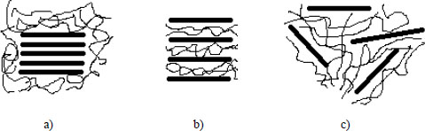
Figure 1.11. Representations of the different morphologies of nanocomposites encountered in the case of silicate nanofillers that can be applied to graphite. Phases: a) separated, b) intercalated and c) exfoliated (Bhattacharya 2016)
For example, Huang et al. (2010) employ both SEM and TEM imaging techniques to characterize the morphology of their PP/GO composites produced by in situ polymerization. Their preparation method based on the surface grafting of their GOs with Ziegler–Natta catalysts enables the surface polymerization of carbon planes promoting their exfoliation. Using these methods, it is possible to highlight the presence of nanofillers and characterize their states of dispersion, but also estimate the number of planes composing the GO fillers after preparation, as well as appreciate the quality of the adhesion of the matrix to the filler. It should be noted, however, that some morphologies are difficult to observe, especially in the case of particularly exfoliated fillers, namely in the form of perfectly isolated sheets in the matrix, either by TEM or X-ray (Paul and Robeson 2008; Kim et al. 2010b). In addition, the cryomicrotomy cutting necessary for sampling can prove complicated depending on the matrix employed.
1.4.2. Influence of nanofillers on semi-crystalline microstructures
In the case of a semicrystalline matrix, the carbon filler can impact the crystallinity rate, the thicknesses of crystalline lamella and/or the crystallization speed. In the case of PP, carbon planes behave as nucleating agents, but limit macromolecular mobility and thus crystal lamella growth (Kalaitzidou et al. 2008; Yuan et al. 2014; He et al. 2018). Filler compatibility with the matrix, as well as processing and dispersion conditions play a very important role. Therefore, in their work comparing in situ polymerization and melt-mixing processing methods, Cromer et al. (2015) show that in both situations an increase in the melting temperature of their iPPs results in a higher crystallinity rate as a function of the increasing mass fraction of carbon particles. However, this result is twice as large for materials obtained by melt mixing. In contrast, Bafana et al. (2017) show a decrease in the crystallinity rate and only a very small variation in the melting temperature for their materials produced by a solution-mixing method. On the other hand, Hsiao et al. (2011), in their work on nanofiller grafting, show a strong difference between PP/TRGO materials produced by simply dispersing their nanofillers, and PP/PP-g-TRGO materials, in which the matrix and the nanofiller exhibit covalent bonds and thus better compatibility. This difference in behavior highlights the importance of the compatibility between the matrix and the filler in the production of nanocomposites.
The crystallization rate of a matrix is also strongly impacted by the insertion of fillers in a semi-crystalline matrix. In the case of PP, several authors have studied the effect of graphite fillers and its derivatives on the crystallization rate, as well as on the final morphology of the material depending on the amount, but also the size of the nanofiller (Kalaitzidou et al. 2008; Zhao et al. 2014; Jun et al. 2018a). Zhao et al. (2014) observe that the presence of graphite, even at low concentration, allows surface, but especially edge nucleation of carbon sheets at temperatures higher than pure materials. The preferential localization at the edge of the sheets can be explained by the presence of a greater number of defects in the structure of the filler, making a better nucleation possible. The authors also observe a decrease in the size of the crystalline structures due to their greater number and the space limited by the presence of graphite. These results are confirmed in the work of Kalaitzidou et al. (2008) on the crystallization of a PP charged with different graphite fillers. The crystallization rate increases significantly with the addition of graphite: it can triple between a virgin PP and a PP/GNP at 0.01 wt%, and sixfold for concentrations up to 1 wt%. This increase of the crystallization rate, but also of the number of spherulites developing around the nanofillers, implies a decrease in their final sizes.
The effect of the size of the graphite filler in terms of diameter is also studied by Kalaitzidou et al. (2008). Their optical analyses show that at equivalent loading rates, the materials with the largest loads crystallize as larger spherulites, while exhibiting close crystallinity rates. The X-ray diffraction analysis shows a significant difference between the materials containing a filler of 1 μm and 15 μm diameter. While increasing the concentration of both fillers impacts the α-phase of iPP in the same way – an increase in the intensity of the diffraction peaks of the plane family (00l) is observed – a difference appears for the β-phase confirmed by Jun et al. (2018b). The 1 μm diameter fillers at low concentrations (0.01 wt%) enable the crystallization of the material under its β phase, but not at higher concentrations (1 wt%). On the contrary, the addition of the 15 μm diameter filler systematically induces a β-phase even at higher concentrations (e.g. 10 wt%). This difference comes from the large number of nucleation points created by the 1 μm diameter fillers, which by rapidly occupying the available space do not allow the formation of β-spherules. The appearance of the β phase is also indicated by other studies (Shanks and Cerezo 2012; Ruy and Shanmugharaj 2014; Ahmad et al. 2017; He et al. 2018; Rosehr et al. 2018). In general, the nucleating effect is higher for smaller fillers because they provide a larger specific surface area of contact with the matrix and limit the movement of polymer chains less (Vallés et al. 2014).
1.4.3. Influence of nanofillers on mechanical properties
One of the main reasons for adding a carbon or another nanofiller to a polymer matrix is to improve its mechanical properties. Therefore, the effect of carbon nanofillers on the mechanical properties of polymer matrices is studied in many formulations, and as in the case of the influence on the microstructure, the effects vary greatly depending on the chosen configuration. For example, exfoliated graphene fillers appear to be more suitable for mechanical reinforcements than black or carbon nanotube fillers (Kim et al. 2010a; Bhattacharya 2014). Similarly, the compatibility between filler and matrix can greatly influence the mechanical properties of the materials. Polar polymers such as PVA, PMMA and PAN, but also epoxy matrices, are known for large increases in their Young’s moduli and glass transition temperatures with the addition of carbon nanofillers, especially GO, due to the non-covalent bonds that can be created between the matrix and the chemical groups present on the surface of the carbon particles (Ramanathan et al. 2008; Rafiee et al. 2009; Ren et al. 2018). In general, carbon nanofillers induce an increase in the Young modulus and tensile strength of the material, parallel to the rate under load. Thus, it is generally accepted that the nanofiller limits the movement of the macromolecular chains of the material, leading to its stiffening. This evolution is generally achieved to the detriment of the elongation at break of the material and depends on the adhesion between filler and matrix.
These trends are observed in the case of PP-based nanocomposites. For example, Jun et al. (2018a) show that the addition of large-diameter GNPs (>150 μm) at 1.3 wt% allows the increase of the Young modulus of their PP matrices from 514 to 540 MPa, but strongly decreases its elongation at break, ranging from 908% to only 17%. Some authors also note a loss of ductility of the nanocomposite (Song et al. 2011; Yuan et al. 2014; Rosehr et al. 2018). This decrease can be explained by the tendency of the fillers to agglomerate, making decohesion with the matrix easier. Zhao et al. (2010) compare this condition to filler “mechanical percolation”. Improved filler dispersion and exfoliation yields better mechanical properties. Cromer et al. (2015), in their comparisons of in situ polymerization and melt-mixing methods, note that at equivalent filler rates a better ductility of their matrices is produced by the first method, for which a better dispersion state was observed. Similarly, Kalaitzidou et al. (2007b, 2008) observe an improvement of the mechanical properties of their composites via their method of elaboration by coating, also resulting from better filler dispersion.
In addition to the dispersion quality, the size of the fillers has an influence on the final mechanical properties of the nanocomposite. As previously stated, it influences PP crystallization, in particular by promoting the development of the β-crystalline phase which, although the latter presents a better impact strength than the α-phase, shows lower mechanical tensile strength. More generally, Young et al. (2018) explain that the stress transfer between the matrix and the nanofiller and the Young modulus of the nanocomposites are globally independent of the intrinsic properties of the nanofiller, but mainly depend on their form factor and compatibility with the matrix. Jun et al. (2018b) thus compare four types of GNPs with different diameters: 2 μm (C300), 5 μm (M5), 25 μm (M25) and 150 μm (H100), for mass concentrations ranging from 1 to 10 wt%. The results of their mechanical analyses are presented in Figure 1.12. The range of nanocomposites filled with H100 GNPs shows an increase in Young’s modulus with the carbon concentration, but a low tensile strength, while the other three ranges show an improvement of both parameters, but all at the expense of the elongation at break. This evolution in H100 materials is explained by the large size of the carbon sheets that fold and form large agglomerates. On the contrary, the materials based on the smaller filler sizes show an improvement in both their Young’s moduli and their tensile strength, with a maximum reached for the C300 filler, the smallest in this study. Therefore, decreasing the size of the filler makes it possible, at equivalent loading rates, to increase the contact area and thus achieve a better stress transfer between the matrix and the filler (Kuvardina et al. 2013; Liang et al. 2016).
Finally, the last parameter that can influence the mechanical properties is the compatibility of the matrix with the surface of the filler. A compatibility agent is then used as an intermediary to yield a better mechanical filler transfer.
Rosehr et al. (2018) employ atactic PP chains as compatibilizing agents on the surface of GNPs when performing a masterbatch. After mixing within an iPP matrix, the resulting materials exhibit tensile strength equivalent to a composite produced without a masterbatch step, but show higher elongation at break, as shown in Figure 1.13. It is interesting to note that the elongation at break is all the higher when the aPP mass fraction is large. The presence of aPP chains on the surface of the carbon ensures a better transfer of the stress and limits the phenomenon of filler/matrix decohesion within the nanocomposite.
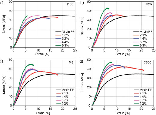
Figure 1.12. Nominal behavior laws of different PP/GNP composites with the fillers: a) H100, b) M25, c) M5, and d) C300, for a volume concentration ranging from 1.3 to 9.3% (Jun et al. 2018b). For a color version of this figure, see www.iste.co.uk/bai/nanocomposites.zip
Other authors use grafting of different functional chemical groups such as maleic anhydride onto the macromolecular chains. The resulting chemical adhesion induces a net improvement of the dispersion of the filler within its matrix, but also allows the significant improvement of its mechanical properties (Colbeaux et al. 2005; Li et al. 2017). The main drawback of these methods originates from the impact of these groups and their grafting operations on the properties of the pristine matrix. Other types of grafting are listed in the literature, and those inducing covalent bonds with the filler provide significant improvement in mechanical properties (Hsiao et al. 2011; Ryu and Shanmugharaj 2014).
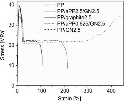
Figure 1.13. Nominal mechanical behavior of a PP and of different composites (Rosehr et al. 2018)
1.4.4. Influence of nanofillers on electrical properties
Regardless of their shapes, the choice of carbon nanofillers in the development of a nanocomposite is mainly due to their excellent electrical properties compared to other fillers (Bhattacharya 2016). However, in order to avoid having to add them in too large quantities, which could adversely affect other properties of the final material, the best method to increase conductivity is to improve dispersion by reducing the agglomeration phenomenon. This strong impact of dispersion is explained by the phenomenon of percolation of the charge within the matrix by the creation of a necessary and essential conductive lattice (Kirkpatrick 1973; Lux 1993).
1.4.4.1. The role of percolation
During the preparation of a nanocomposite, three states are possible, according to the rate of charge and the dispersion of the latter. At a low loading rate, the fillers are separated by the insulating matrix, the conductivity of the material is then close to that of the initial matrix. As the load rate increases, the filler-to-filler contact becomes more frequent, until a threshold concentration is reached, called the percolation threshold, from which the charges form a continuous lattice in the material, called a percolated lattice. The electrical conductivity of the material then presents a strong increase. Beyond this threshold, the conductivity of the material stabilizes at values close to the conductivity of the filler. In addition to this contact conductivity, the phenomenon of “tunneling” occurs for sufficiently close charges, for distances less than 10 nm, enabling electrical conductivity before the contact percolated lattice is formed (Al-Saleh and Sundararaj 2009; Stauffert et al. 2009). Figure 1.14 shows the different possible configurations. In case of poor filler distribution and dispersion (configuration (a)), and in case of good distribution but poor dispersion (configuration (b)), no conductive lattice is formed. In case of good distribution and dispersion (configuration (d)), the distance between the charges can prevent the formation of the network. At low filler concentration, the optimal configuration is therefore configuration (c), with good dispersion, but a distribution of fillers enabling the formation of the continuous network.
Many parameters are involved in the percolation phenomenon, whether it is the polymer matrix used, its compatibility with the filler, the preparation method, or the form factor of the filler. In their review on the production of polymer/graphene nanocomposites, Potts et al. (2011) compare the lowest electrical percolation thresholds obtained with several polymer/filler configurations. Their observations are summarized in Table 1.2. Significant variations in the percolation threshold are observed, down to values below 0.2 wt% for an oxidized polyethylene/graphene composite, as seen for the solution-based preparation by Pang et al. (2010).
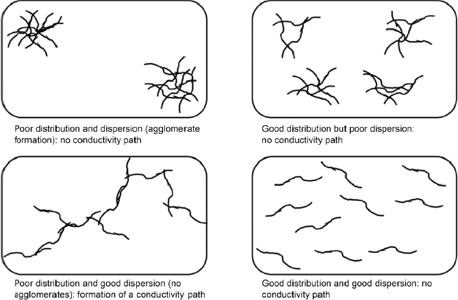
Figure 1.14. Schematic representation of the possible distributions and dispersions of fillers within a polymer matrix (Al-Saleh and Sudararaj 2009)
Table 1.2. Comparison of different percolation rates obtained as a function of the matrix/filler configurations (Potts et al. 2011)
| Polymer matrix | Nanofiller | Percolation threshold (wt%) | Reference |
| Epoxy | Fonct. EG | 1.0 | (Miller et al. 2010) |
| Nylon-6 | GO | 0.5 | (Du et al. 2010) |
| Polyaniline (doped) | GNP | 0.7 | (Wu et al. 2010b) |
| Polycarbonate | TEGO | 0.3 | (Khanam et al. 2016) |
| Polyethylene | RG-O | 0.15 | (Pang et al. 2010) |
| Polyethylene terephthalate | TEGO | 1.0 | (Zhang et al. 2010) |
| Polymethyl methacrylate | GNP | 0.7 | (Chen et al. 2003a) |
| Polypropylene | GNP | 0.7 | (Kalaitzidou et al. 2007b) |
| Polystyrene | Fonct. GO | 0.2 | (Stankovich et al. 2006) |
| Polyvinyl alcohol | RG-O | 0.5 | (Salavagione et al. 2009) |
| Polyvinyl chloride | GNP | 1.4 | (Vadukumpully et al. 2011) |
| Polyvinylidene fluoride | TEGO | 2.0 | (Ansari et al. 2009) |
| Polyurethane | TEGO | 0.6 | (Kim et al. 2010b) |
1.4.4.2. Evolution of electrical properties
As in the case of the influence on the microstructure and on the mechanical properties, many parameters influence the electrical properties of the nanocomposite, such as the size of the charge, its dispersion, the compatibility with the matrix, but also in the case of semi-crystalline materials, the crystallinity of the material. It is possible, depending on the configuration, to reach electrical conductivities of the order of S·cm–1 (Kalaitzidou et al. 2007b; Jun et al. 2018a).
He et al. (2018) show that the use of ultrasound during the preparation of their materials allows an increase in the conductivity of the materials, resulting in a better dispersion. This difference in percolation, according to the quality of the dispersion, is particularly visible in the work by Kalaitzidou et al. (2008), who compare the levels of dispersion obtained according to the methods of elaboration in solution and by melt mixing. The latter shows a percolation threshold above 5 vol%, while the solution method gives a percolation between 0 and 3 vol% (Figure 1.15).
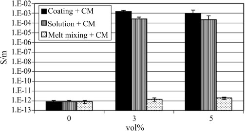
Figure 1.15. Evolution of electrical conductivity in PP/GNP nanocomposites according to the preparation method used (Kalaitzidou et al. 2008)
Jun et al. (2018a) show a difference in the electrical properties of their PP/GNP materials depending on the size of the introduced fillers. The first observation made by the authors is the lack of change in electrical conductivity with the addition of their smallest filler (2 μm diameter). The larger the filler diameter, the lower the percolation threshold, which is in agreement with previous results on the filler size/percolation threshold relation proposed by Wu et al. (2013) and Jun et al. (2015). It is interesting to note that this evolution is to the advantage of large diameter fillers and is in contrast to the previously observed evolutions related to microstructure and mechanical properties, both of which are more favorable to small-sized fillers. A trade-off must then be found between electrical and mechanical properties.
Kalaitzidou et al. (2008) show that the cooling rate of the material during its preparation strongly impacts the percolation threshold of the nanocomposite. Indeed, the percolation threshold is four to five times lower for materials cooled slowly. This difference is explained at the microstructural level. During fast cooling, a large number of small spherulites form on the surface of the carbon films and block the formation of the electrical percolation lattice, whereas slow cooling allows for the formation of large spherulites favorable to percolation.
A similar finding can be made for nanocomposites utilizing compatibilizing agents that allow covalent-type adhesion between the matrix and the filler. The better dispersion obtained via this method is responsible for a decrease in the percolation threshold, as well as an increase in conductivity (Hsiao et al. 2011; Ryu and Shanmugharaj 2014; Li et al. 2017).
1.4.5. Evolution of the thermal resistance
One of the known consequences of the addition of a carbon nanofiller within a polymer matrix is the increase of matrix thermal stability. This can be observed in air thermogravimetric analysis (ATG) by an increase in the degradation temperature of the material with the filler ratio. For example, Bafana et al. (2017) obtain an increase in the degradation temperature of their iPP with the addition of graphene (Figure 1.16).
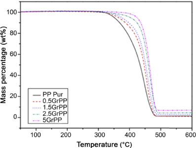
Figure 1.16. Evolution of mass losses measured by ATG under air of pure iPP and its nanocomposites loaded with different graphene filler rates (Bafana et al. 2017). For a color version of this figure, see www.iste.co.uk/bai/nanocomposites.zip
This increase in material degradation temperature is not linear with increasing loading rate, but increases significantly from low values and then reaches an asymptote (Song et al. 2011; Kuvardina et al. 2013; Zhao et al. 2014; Ahmad et al. 2017; Ren et al. 2018). This peculiarity can be explained by the role of nanofillers in the permeability to gases, more specifically to the oxygen of the nanocomposite. Indeed, the graphene sheets, if devoid of defects, present an impermeability to gaseous molecules and thus make it possible to limit their diffusion within, and through, the polymer matrix (Bunch et al. 2008). The resulting nanocomposites then become good candidates as protective materials against corrosion, in the form of an impermeable film (Yang et al. 2013). At equivalent filler ratio, the effect is more important for small diameter fillers (Figure 1.17) due to the increase in the interaction surface between the filler and the matrix (Vadukumpully et al. 2011; Beuguel et al. 2018). Improved compatibility between matrix and filler implies better thermal energy diffusion in the matrix and thus also improves the thermal resistance of the composite. On the other hand, Hsiao et al. (2011) find that the addition of 0.1wt% of a TRGO filler induces an increase in the thermal degradation temperature of an iPP. This property is only promoted if the filler is grafted to the matrix.
Finally, we note that the large difference between the degradation temperatures of the polymer and the nanofiller enables, after preparation, a verification of the mass percentage remaining after complete degradation of the polymer matrix.
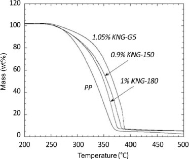
Figure 1.17. ATG analyses under air of different PP/GNP composites for GNPs of different sizes (increasing order of size: G5, KNG 150, KNG 180) (Beuguel et al. 2018)
1.5. References
Afanasov, I.M., Shornikova, O.N., Kirilenko, D.A. (2010). Graphite structural transformations during intercalation by HNO3 and exfoliation. Carbon, 48(6) 1862–1865.
Ahmad, S.R., Xue, C., Young, R.J. (2017). The mechanisms of reinforcement of polypropylene by graphene nanoplatelets. Materials Science and Engineering: B, 216, 2–9.
Al-Saleh, M.H. and Sundararaj, U. (2009). A review of vapor grown carbon nanofiber/polymer conductive composites. Carbon, 47, 2–22.
Anders, A. (2009). Cathodic Arcs: From Fractal Spots to Energetic Condensation. Springer, New York.
Ansari, S. and Giannelis, E.P. (2009). Functionalized graphene sheet-poly(vinylidene fluoride) conductive nanocomposites. Journal of Polymer Science Part B: Polymer Physics, 47(9), 888–897.
Bae, S., Kim, H., Lee, Y. (2010). Roll-to-roll production of 30-inch graphene films for transparent electrodes. Nature Nanotechnology, 5(8), 574–578.
Bafana, A.P., Yan, X., Wei, X., Patel, M., Guo, Z., Wei, S., Wujcik, E.K. (2017). Poly-propylene nanocomposites reinforced with low weight percent graphene nanoplatelets. Composites: Part B, 109, 101–107.
Bagri, C., Matteri, C., Acik, M. (2010). Structural evolution during the reduction of chemically derived graphene oxide. Nature Chemistry, 2(7), 581–587.
Banhart, F., Kotakoski, J., Krasheninnikov, A.V. (2011). Structural defects in graphene. ACS Nano, 5(1), 26–41.
Bao, R.Y., Cao, J., Liu, Z.Y., Yang, W., Xie, B.X., Yang, M.B. (2014). Towards balanced strength and toughness improvement of isotactic polypropylene nanocomposites by surface functionalized graphene oxide. Journal Materials Chemistry: A, 2(9), 3190–3199.
Becerril, H.A., Mao, J., Liu, Z. (2008). Evaluation of solution-processed reduced graphene oxide films as transparent conductors. ACS Nano, 2(3), 463–470.
Berry, V. (2013). Impermeability of graphene and its applications. Carbon, 62, 1–10.
Beuguel, Q., Mija, A., Vergnes, B., Peuvrel-Disdier, E. (2018). Structural, thermal, rheological and mechanical properties of polypropylene/graphene nanoplatelets composites: Effect of particle size and melt mixing conditions. Polymer Engineering and Science, 58(11), 1937–1944.
Bhattacharya, M. (2016). Polymer nanocomposites: A comparison between carbon nanotubes, graphene, and clay as nanofillers. Materials, 9(4), 262.
Bianco, A., Cheng, H.M., Enoki, T., Gogotsi, Y., Hurt, R.H., Koratkar, N., Kyotani, T., Monthioux, M., Park, C.R., Tascon, J.M.D., Zhang, J. (2013). All in the graphene family – A recommended nomenclature for two-dimensional carbon materials. Carbon, 65, 1–6.
Boehm, H.P., Clauss, A., Fischer, G. (1962). Surface properties of extremely thin graphite lamellae. Proceedings of the Fifth Conference on Carbon, 73–80.
Bolotin, K.I., Sikes, K.J., Jiang, Z., Klima, M., Fudenberg, G., Hone, J. (2008). Ultra-high electron mobility in suspended graphene. Solid State Communications, 146(9), 351–355.
Botas, C., Alvarez, P., Blanco, C., Santamaria, R., Granda, M., Ares, P., Rodriguez-Reinoso, F., Menendez, R. (2012). The effect of the parent graphite on the structure of graphene oxide. Carbon, 50(1), 275–282.
Botas, C., Alvarez, P., Blanco, P., Granda, M., Blanco, C., Santamaria, R., Romasanta, L.J., Verdejo, R., Lopez-Manchado, M., Menendez, R. (2013). Graphene materials with different structures prepared from the same graphite by the Hummers and Brodie methods. Carbon, 65, 156–164.
Brault, P., Caillard, A., Baranton, S., Mougenot, M., Cuynet, S., Coutanceau, C. (2013). One-step synthesis and chemical characterization of Pt–C nanowire composites by plasma sputtering. ChemSusChem, 6(7), 1168–1171.
Bruggeman, P.J., Kushner, M.J., Locke, B.R., Gardeniers, J.G.E., Graham, W.G., Graves, D.B., Hofman-Caris, R.C.H.M., Maric, D., Reid, J.P., Ceriani, E. (2016). Plasma–liquid interactions: A review and roadmap. Plasma Sources Science and Technology, 25(5), 053002.
Bunch, J.S., Verbridge, S.S., Alden, J.S., Van der Zande, A.M., Parpia, J.M., Craighead, H.G., McEuen, P.L. (2008). Impermeable atomic membranes from graphene sheets. Nano Letters, 8(8), 2458–2462.
Canales, J., Fernadez, M., Pena, J.J., Munoz, M.E., Santamaria, A. (2015). Rheological methods to investigate graphene/amorphous polyamide nanocomposites: Aspect ratio, processing, and crystallization. Polymer Engineering and Science, 55(5), 1142–1151.
Catheline, A., Vallés, C., Drummond, C., Ortolani, L., Morandi, V., Marcaccio, M., Iurlo, M., Paolucci, F., Penicaud, A. (2011). Graphene solutions. Chemical Communications, 47(19), 5470–5472.
Catheline, A., Ortolani, L., Morandi, V., Melle-Franco, M., Drummond, C., Zakri, C., Pénicaud, A. (2012). Solutions of fully exfoliated individual graphene sheets in low boiling point solvents. Soft Matter, 8(30), 7882–7887.
Chen, G., Weng, W., Wu, D., Wu, C. (2003a). PMMA/graphite nanosheets composite and its conducting properties. European Polymer Journal, 39(12), 2329–2335.
Chen, G., Wu, C., Weng, W., Wu, D., Yan, W. (2003b). Preparation of polystyrene/graphite nanosheet composite. Polymer, 44(6), 1781–1784.
Colbeaux, A., Fenouillot, F., Gerard, J.F., Taha, M., Wautier, H. (2005). Diamine coupling of maleic anhydride modified polyethylene. Polymer International, 54(4), 692–697.
Cromer, B.M., Scheel, S., Luinstra, G.A., Coughlin, E.B., Lesser, A.J. (2015). In situ polymerization of isotactic polypropylene-nanographite nanocomposites. Polymer, 80, 275–281.
Cui, L. and Paul, D.R. (2007). Evaluation of amine functionalized polypropylenes as compatibilizers for polypropylene nanocomposites. Polymer, 48(6), 1632–1640.
Dey, A., Chroneos, A., Braithwaite, N.S.J., Gandhiraman, R.P., Krishnamurthy, S. (2016). Plasma engineering of graphene. Applied Physics Reviews, 3(2), 021301.
Dhar, S., Barman, A.R., Ni, G.X. (2011). A new route to graphene layers by selective laser ablation. AIP Advances, 1(2), 022109.
Dreyer, D.R., Park, S.J., Bielawski, C.W. (2010). The chemistry of graphene oxide. Chemical Society Reviews, 39(1), 228–240.
Du, N., Zhao, C.Y., Chen, Q., Wu, G., Lu, R. (2010). Preparation and characterization of nylon 6/graphite composite. Materials Chemistry and Physics, 120(1), 167–171.
Fang, M., Wang, K., Lu, H., Yang, Y., Nutt, S. (2009). Covalent polymer functionalization of graphene nanosheets and mechanical properties of composites. Journal of Materials Chemistry, 19(38), 7098–7105.
Fernandez-Merino, M.J., Guardia, L., Paredes J.I. (2010). Vitamin C is an ideal substitute for hydrazine in the reduction of graphene oxide suspensions. Journal of Physical Chemistry C, 114(14), 6426–6432.
Ferrari, A.C., Bonaccorso, F., Fal’Ko, V.I., Novoselov, K.S., Roche, S., Boggild, P., Garrido, J.A. (2015). Science and technology roadmap for graphene, related two-dimensional crystals, and hybrid systems. Nanoscale, 7(11), 4598–4810.
Figuereido, J.L., Pereira, M.F.R., Freitas, M.M.A. (1999). Modification of the surface chemistry of activated carbons. Carbon, 37(9), 1379–1389.
Fim, F.C., Guterres, J.M., Basso, N.R.S., Galland, G.B. (2010). Polyethylene/graphite nanocomposites obtained by in situ polymerization. Journal of Polymer Science: Part A: Polymer Chemistry, 48, 692–698.
Furdin, G. (1998). Exfoliation process and elaboration of new carbonaceous materials. Fuel, 77(6), 479–485.
Furdin, G., Marêché, J.F., Hérold, A. (1991). Graphite micronique plat, procédé pour sa préparation et ses applications. Brevet français no. 91–12663.
Gao, W., Alemany, L.B., Ci, L. (2009). New insights into the structure of graphite oxide. Nature Chemistry, 1(5), 403–408.
Giorcelli, M., Guastella, S., Mandracci, P., Liang, Y., Li, X., Tagliaferro, A. (2018). Carbon fibre functionalization by plasma treatment for adhesion enhancement on polymers. AIP Conference Proceedings, 1981, 020142.
Gomez-Navarro, C., Weitz, R.T., Bittner, A.M. (2007). Electronic transport properties of individual chemically reduced oxide graphene sheets. Nano Letters, 7(11), 3499–3503.
Green, A.A. and Hensen, M.C. (2009). Solution phase production of graphene with controlled thickness via density differentiation. Nano Letters, 9(12), 4031–4036.
Gulrez, S.K.H., Mohsin, M.E.A., Shaikh, H., Anis, A., Pulose, A.M., Yadav, M.K., Qua, A.H.P., Al-Zahrani, S.M. (2013). A review on electrically conductive polypropylene and polyethylene. Polymer Composites, 35, 900–914.
Hamdan, A., Marinov, I., Rousseau, A., Belmonte, T. (2013a). Time-resolved imaging of nanosecond-pulsed micro-discharges in heptane. Journal of Physics D: Applied Physics, 47, 055203.
Hamdan, A., Noel, C., Kosior, F., Henrion, G., Belmonte, T. (2013b). Dynamics of bubbles created by plasma in heptane for micro-gap conditions. The Journal of the Acoustical Society of America, 134, 991–1000.
He, S., Zhang, J., Xiao, X., Hong, X. (2018). Effects of ultrasound vibration on the structure and properties of polypropylene/graphene nanoplatelets composites. Polymer Engineering and Science, 58(3), 377–386.
Hernandez, Y., Nicolosi, V., Lotya, M. (2008). High-yield production of graphene via liquid-phase exfoliation of graphite. Nature Nanotechnology, 3(9), 563–568.
Hsiao, M.C., Liao, S.H., Lin, Y.F., Wang, C.A., Pu, N.W., Tsai, H.M., Ma, C.C. (2011). Preparation and characterization of polypropylene-graft-thermally reduced graphite oxide with an improved compatibility with polypropylene-based nanocomposite. Nanoscale, 3(4), 1516–1522.
Huang, Y.J., Qin, Y., Zhou, Y., Niu, H., Yu, Z.Z., Dong, J.Y. (2010). Polypropylene/graphene oxide nanocomposites prepared by in situ Ziegler–Natta polymerization. Chemistry of Materials, 22(13), 4096–4102.
Hummers, W.S. and Offeman, R.E. (1958). Preparation of graphitic oxide. Journal of the American Chemical Society, 208(1937), 1339–1339.
Inagaki, M. and Tashiro, R. (2004). Exfoliation process of graphite via intercalation compounds with sulfuric acid. Journal of Physics and Chemistry of Solids, 65(2–3), 133–137.
Jang, B.Z. and Zhamu, A. (2008). Processing of nanographene platelets (NGPs) and NGP nanocomposites: A review. Journal of Material Science, 43(15), 5092–5101.
Jun, Y.S., Sy, S., Ahn, W., Zarrin, H., Rasen, L., Tjandra, R., Amoli, B.M., Zhao, B., Chiu, G., Yu, A. (2015). Highly conductive interconnected graphene foam based polymer composite. Carbon, 95, 653–658.
Jun, Y.S., Um, J.G., Jiang, G., Lui, G., Yu, A. (2018a). Ultra-large sized graphene nanoplatelets (GnPs) incorporated polypropylene (PP)/GnPs composites engineered by melt compounding and its thermal, mechanical, and electrical properties. Composites: Part B, 133(15), 218–225.
Jun, Y.S., Um, J.G., Jiang, G., Yu, A. (2018b). A study on the effects of graphene nanoplatelets (GnPs) sheet sizes from a few to hundred microns on the thermal, mechanical, and electrical properties of polypropylene (PP)/GnPs composites. eXPRESS Polymer Letters, 12(10), 885–897.
Kalaitzidou, K., Fukushima, H., Drzal, L.T. (2007a). Multifunctional polypropylene composites produced by incorporation of exfoliated graphite nanoplatelets. Carbon, 45(7), 1446–1452.
Kalaitzidou, K., Fukushima, H., Drzal, L.T. (2007b). A new compounding method for exfoliated graphite–polypropylene nanocomposites with enhanced flexural properties and lower percolation threshold. Composites Science and Technology, 67(10), 2045–2051.
Kalaitzidou, K., Fukushima, H., Askeland, P., Drzal, L.T. (2008). The nucleating effect of exfoliated graphite nanoplatelets and their influence on the crystal structure and electrical conductivity of polypropylene nanocomposites. Journal of Materials Science, 43(8), 2895–2907.
Kernina, A., Wana, K., Liu, Y., Shi, X., Kong, J., Bilotti, E., Peijs, T., Zhang, H. (2019). The effect of graphene network formation on the electrical, mechanical, and multi-functional properties of graphene/epoxy nanocomposites. Composites Science and Technology, 169, 224–231.
Khan, U., O’Neill, A., Lotya, M. (2008). High-concentration solvent exfoliation of graphene. Small, 6(7), 864–871.
Khanam, P.N., Al-Maadeed, M.A., Ouederni, M., Harkin-Jones, E., Mayoral, B., Hamilton, A., Sun, D. (2016). Melt processing and properties of linear low density polyethylenegraphene nanoplatelet composites. Vacuum, 130, 63–71.
Kim, H. and Macosko, C.W. (2009). Processing-property relationships of polycarbonate/graphene composites. Polymer, 50(15), 3797–3809.
Kim, J. and Suh, J.S. (2014). Size-controllable and low-cost fabrication of graphene quantum dots using thermal plasma jet. ACS Nano, 8(5), 4190–4196.
Kim, H., Abdala, A.A., Macosko, C.W. (2010a). Graphene/polymer nanocomposites. Macromolecules, 43(16), 6515–6530.
Kim, H., Miura, Y., Macosko, C.W. (2010b). Graphene/polyurethane nanocomposites for improved gas barrier and electrical conductivity. Chemistry of Materials, 22(11), 3441–3450.
Kirkpatrick, S. (1973). Percolation and conduction. Reviews of Modern Physics, 45(4), 574–588.
Kuvardina, E.V., Novokshonova, L.A., Lomakin, S.M., Timan, S.A., Tchmutin, I.A. (2013). Effect of the graphite nanoplatelet size on the mechanical, thermal, and electrical properties of polypropylene/exfoliated graphite nanocomposites. Journal of Applied Polymer Science, 128(3), 1414–1424.
Lee, C., Wei, X., Kysar, J.W., Hone, J. (2008). Measurement of the elastic properties and intrinsic strength of monolayer graphene. Science, 321(5887), 385–388.
Létoffé, A., García-Rodríguez, S.M., Hoppe, S., Canilho, N., Godard, O., Pasc, A., Royaud, I., Ponçot, M. (2019). Switching from brittle to ductile isotactic polypropylene-g-maleic anhydride by crosslinking with capped-end polyether diamine. Polymer, 164, 67–78.
Levchenko, I., Ostrikov, K., Zheng, J., Li, X., Keidard, M., Teo, K.B.K. (2016). Scalable graphene production: Perspectives and challenges of plasma applications. Nanoscale, 8(20), 10511–10527.
Li, Y., Chen, Q., Xu, K., Kaneko, T., Hatakeyama, R. (2013). Synthesis of graphene nanosheets from petroleum asphalt by pulsed arc discharge in water. Chemical Engineering Journal, 215–216, 45–49.
Li, C.Q., Zha, J.W., Long, H.Q., Wang, S.J., Zhang, D.L., Dang, Z.M. (2017). Mechanical and dielectric properties of graphene incorporated polypropylene nanocomposites using polypropylene-graft-maleic anhydride as a compatibilizer. Composites Science and Technology, 153, 111–118.
Li, X., Bandyopadhyay, P., Nguyen, T.T., Park, O.K., Lee, J.H. (2018). Fabrication of functionalized graphene oxide/maleic anhydride grafted polypropylene composite film with excellent gas barrier and anticorrosion properties. Journal of Membrane Science, 547, 80–92.
Liang, J.Z., Du, Q., Tsui, G.C.P., Tang, C.Y. (2016). Tensile properties of graphene nanoplatelets reinforced polypropylene composites. Composites Part B: Engineering, 95, 166–171.
Lotya, M., Hernandez, Y., King, P.J. (2009). Liquid phase production of graphene by exfoliation of graphite in surfactant/water solutions. Journal of the American Chemical Society, 131(10), 3611–3620.
Lukes, P., Dolezalova, E., Sisrova, I., Clupek, M. (2014). Aqueous-phase chemistry and bactericidal effects from an air discharge plasma in contact with water: Evidence for the formation of peroxynitrite through a pseudo-second-order post-discharge reaction of H2O2 and HNO2. Plasma Sources Science and Technology, 23(1), 015019.
Lux, F. (1993). Models proposed to explain the electrical conductivity of mixtures made of conductive and insulating materials. Journal of Materials Science, 28(2), 285–301.
Ma, J., Li, Y., Yin, X., Xu, Y., Yue, J., Bao, J., Zhou, T. (2016). Poly(vinyl alcohol)/graphene oxide nanocomposites prepared by in situ polymerization with enhanced mechanical properties and water vapor barrier properties. RSC Advances, 6(55), 49448–49458.
Malesevic, A., Vitchev, R., Schouteden, K., Volodin, A., Zhang, L., Van Tendeloo, G., Vanhulsel, A., Van Haesendonck, C. (2008). Synthesis of few-layer graphene via microwave plasma-enhanced chemical vapour deposition. Nanotechnology, 19(30), 305604.
McAllister, M.J., Li, J.L., Adamson, D.H. (2007). Single sheet functionalized graphene by oxidation and thermal expansion of graphite. Chemistry of Materials, 19(18), 4396–4404.
Miller, S.G., Bauer, J.L., Maryanski, M.J., Heinmann, P.J., Barlow, J.P., Gosau, J.M., Allred, R.E. (2010). Characterization of epoxy functionalized graphite nanoparticles and the physical properties of epoxy matrix nanocomposites. Composites Science and Technology, 70(7), 1120–1125.
Notley, S.M. (2012). Highly concentrated aqueous suspensions of graphene through ultrasonic exfoliation with continuous surfactant addition. Langmuir, 28(40), 14110–14113.
Novoselov, K.S., Geim, A.K., Mozorov, S.V. (2004). Electric field effect in atomically thin carbon films. Science, 306(5696), 666–669.
Novoselov, K.S., Fal’ko, V.I., Colombo, L. (2012). A roadmap for graphene. Nature, 490(7419), 192–200.
O’Neill, A., Khan, U., Nirmalraj, P.N. (2011). Graphene dispersion and exfoliation in low boiling point solvents. Journal of Physical Chemistry C, 115(13), 5422–5428.
Oxfall, H., Rondin, J., Bouquey, M., Muller, R., Rigdahl, M., Rychwalski, R.W. (2013). Elongational flow mixing for manufacturing of graphite nanoplatelet/polystyrene composites. Journal of Applied Polymer Science, 128(5), 2679–2686.
Pan, Y.X., Yu, Z.Z., Ou, Y.C., Hu, G.H. (2000). A new process of fabricating electrically conducting nylon 6/graphite nanocomposites via intercalation polymerization. Journal of Polymer Science: Part B: Polymer Physics, 38(12), 1626–1633.
Pang, H., Chen, T., Zhang, G., Zeng, B., Li, Z.M. (2010). An electrically conducting polymer/graphene composite with a very low percolation threshold. Materials Letters, 64(20), 2226–2229.
Paredes, J.I., Villar-Rodil, S., Martinez Alonso, A. (2008). Graphene oxide dispersions in organic solvents. Langmuir, 24(19), 10560–10564.
Paul, D.R. and Robeson, L.M. (2008). Polymer nanotechnology: Nanocomposites. Polymer, 49(15), 3187–3204.
Pol’shchikov, S.V., Nedorezova, P.M., Klyamkina, A.N., Krashenninikov, V.G., Aladyshev, A.M., Shchegolikhin, A.N., Shevchenko, V.G., Sinevich, E.A., Monakhova, T.V., Muradyan, V.E. (2013). Composite materials based on graphene nanoplatelets and polypropylene derived via in situ polymerization. Nanotechnologies in Russia, 8(1/2), 69–80.
Potts, J.R., Dreyer, D.R., Bielawski, C.W., Ruoff, R. (2011). Graphene-based polymer nanocomposites. Polymer, 52(1), 5–25.
Rafiee, M.A., Rafiee, J., Wang, Z., Song, H., Yu, Z.Z., Koratkar, N. (2009). Enhanced mechanical properties of nanocomposites at low graphene content. ACS Nano, 3(12), 3884–3890.
Ramanathan, T., Abdala, A.A., Stankovich, S., Dikini, D.A., Herrera-Alonso, M., Piner, R.D., Adamson, D.H., Schniepp, H.C., Chen, X., Ruoff, R.S., Nguyen, S.T., Aksay, I.A., Prud’Homme, R.K., Brinson, L.C. (2008). Functionalized graphene sheets for polymer nanocomposites. Nature Nanotechnology, 3, 327–331.
Ray, S.S. and Okamoto, M. (2003). Polymer/layered silicate nanocomposites: A review from preparation to processing. Progress in Polymer Science, 28(11), 1539–1641.
Ren, Y., Zhang, Y., Fang, H., Ding, T., Li, J., Bai, S.L. (2018). Simultaneous enhancement on thermal and mechanical properties of polypropylene composites filled with graphite platelets and graphene sheets. Composites: Part A, 112, 57–63.
Rosehr, A., Griebe, D., Luinstra, G.A. (2018). Graphite nanosheets–polypropylene composites from in toluene delaminated graphite using atactic polypropylene as dispersant. Composites Science and Technology, 156, 28–38.
Rutter, G.M., Crain, J.N., Guisinger, N.P., Li, T., First, P.N., Stroscio, J.A. (2007). Scattering and interference in epitaxial graphene. Science, 317(5835), 219–222.
Ryu, S.H. and Shanmugharaj, A.M. (2014). Influence of long-chain alkylamine-modified graphene oxide on the crystallization, mechanical and electrical properties of isotactic polypropylene nanocomposites. Chemical Engineering Journal, 244, 552–560.
Salavagione, H.J., Martinez, G., Gomez, M.A. (2009). Synthesis of poly(vinyl alcohol)/reduced graphite oxide nanocomposites with improved thermal and electrical properties. Journal of Materials Chemistry, 19(28), 5027–5032.
Samukawa, S., Hori, M., Rauf, S., Tachibana, K., Bruggeman, P., Kroesen, G., Whitehead, J.C., Murphy, A.B., Gutsol, A.F., Starikovskaia, S. (2012). The 2012 plasma roadmap. Journal of Physics D: Applied Physics, 45(25), 253001.
Schniepp, H.C., Li, J.L., McAllister, M.J. (2006). Functionalized single graphene sheets derived from splitting graphite oxide. Journal of Physical Chemistry B, 110(17), 8535–8539.
Sengupta, R., Bhattacharya, M., Bandyopadhyay, S., Bhowmick, A.K. (2011). A review on the mechanical and electrical properties of graphite and modified graphite reinforced polymer composites. Progress in Polymer Science, 36(5), 638–670.
Shanks, R.A. and Cerezo, F.T. (2012). Preparation and properties of poly(propylene-g-maleic anhydride) filled with expanded graphite oxide. Composites: Part A, 43(7), 1092–1100.
Shen, J.W., Huang, W.Y., Zuo, S.W., Hou, J. (2005). Polyethylene/grafted polyethylene/graphite nanocomposites: Preparation, structure, and electrical properties. Journal of Applied Polymer Science, 97(1), 51–59.
Shioyama, H. (2000). The interactions of two chemical species in the interlayer spacing of graphite. Synthetic Metals, 114(1), 1–15.
Shukla, A., Kumar, R., Mazher, J. (2009). Graphene made easy: High quality, large area samples. Solid State Communications, 149(17/18), 718–721.
Song, P., Cao, Z., Cai, Y., Zhao, L., Fang, Z., Fu, S. (2011). Fabrication of exfoliated graphene-based polypropylene nanocomposites with enhanced mechanical and thermal properties. Polymer, 52(18), 4001–4010.
Stankovich, S., Dikin, D.A., Dommett, G.H.B., Kohlhaas, K.M., Zimney, E.J., Stach, E.A., Piner, R.D., Nguyen, S.B.T., Ruoff, R.S. (2006). Graphene-based composite materials. Nature, 442, 282–286.
Stankovich, S., Dikin, D.A., Piner, R.D. (2007). Synthesis of graphene-based nano-sheets via chemical reduction of exfoliated graphite oxide. Carbon, 45(7), 1558–1565.
Stauffert, D., Adlerts, J., Aharony, A. (1994). Universality at the three-dimensional percolation threshold. Journal of Physics A: Mathematical and General, 27(13), 475–480.
Subrahmanyam, K.S., Panchakarla, L.S., Govindaraj, A., Rao, C.N.R. (2009). Simple method of preparing graphene flakes by an arc-discharge method. Journal of Physical Chemistry: C, 113(11), 4257–4259.
Traina, M. and Pegoretti, A. (2012). In situ reduction of graphene oxide dispersed in a polymer matrix. Journal of Nanoparticle Research, 14(4), 801–807.
Tsai, H.S., Chih-Chung Lai, C.C., Medina, H., Lin, S.M., Shih, Y.C., Chen, Y.Z., Liang, J.H., Chueh, Y.L. (2014). Scalable graphene synthesised by plasma-assisted selective reaction on silicon carbide for device applications. Nanoscale, 6(22), 13861–13869.
Vadukumpully, S., Paul, J., Mahanta, N., Valiyaveettil, S. (2011). Flexible conductive graphene/poly(vinyl chloride) composite thin films with high mechanical strength and thermal stability. Carbon, 49, 198–205.
Vallés, C., Drummond, C., Saadaoui, H. (2008). Solutions of negatively charged graphene sheets and ribbons. Journal of the American Chemical Society, 130(47), 15802–15804.
Vallés, C., Abdelkader, A.M., Young, R.J., Kinloch, I.A. (2014). Few layer graphene–polypropylene nanocomposites: The role of flake diameter. Faraday Discussions, 173, 379–390.
Wallace, P.R. (1947). The band theory of graphite. Physical Review, 71(9), 622–634.
Wu, H. and Drzal, L.T. (2013). High thermally conductive graphite nanoplatelet/polye-therimide composite by precoating: Effect of percolation and particle size. Polymer Composites, 34(12), 2148–2153.
Wu, C., Dong, G., Guan, L. (2010a). Production of graphene sheets by a simple helium arcdischarge. Physica E: Low-dimensional Systems and Nanostructures, 42(5), 1267–1271.
Wu, X., Qi, S., He, J., Duan, G. (2010b). High conductivity and low percolation threshold in polyaniline/graphite nanosheets composites. Journal of Materials Science, 45(2), 483–489.
Yang, Y.H., Bolling, L., Priolo, M.A., Grunlan, J.C. (2013). Super gas barrier and selectivity of graphene oxide-polymer multilayer thin films. Advanced Materials, 25(4), 503–508.
Young, R.J., Liu, M., Kinloch, I.A., Li, S., Zhao, X., Vallés, C., Papageorgiou, D.G. (2018). The mechanics of reinforcement of polymers by graphene nanoplatelets. Composites Science and Technology, 154, 110–116.
Yuan, B., Bao, C., Song, L., Hong, N., Liew, K.M., Hua, Y. (2014). Preparation of functionalized graphene oxide/polypropylene nanocomposite with significantly improved thermal stability and studies on the crystallization behavior and mechanical properties. Chemical Engineering Journal, 237, 411–420.
Yue, D.W., Ra, C.H., Liu, X.C., Lee, D.Y., Yoo, W.J. (2014). Edge contacts of graphene formed by using a controlled plasma treatment. Nanoscale, 7(2), 825–831.
Zhang, H.B., Zheng, W.G., Yan, Q., Yang, Y., Wang, J.W., Lu, Z.H., Ji, G.Y., Yu, Z.Z. (2010). Electrically conductive polyethylene terephthalate/graphene nanocomposites prepared by melt compounding. Polymer, 51(5), 1191–1196.
Zhao, X., Zhang, Q., Chen, D. (2010). Enhanced mechanical properties of graphene-based poly(vinyl alcohol) composites. Macromolecules, 43(5), 2357–2363.
Zhao, S., Chen, F., Huang, Y.J., Dong, J.Y., Han, C.C. (2014). Crystallization behaviors in the isotactic polypropylene/graphene composites. Polymer, 55(16), 4125–4135.
Zhu, Y., Murali, S., Cai, W., Li, X., Suk, J.W., Potts, J.R., Ruoff, R.S. (2010). Graphene and graphene oxide: Synthesis, properties, and applications. Advanced Materials, 22(35), 3906–3924.