Green composites made from cellulose nanofibers and bio-based epoxy
Processing, performance, and applications
Bamdad Barari and Krishna M. Pillai, University of Wisconsin-Milwaukee, Milwaukee, WI, United States
Abstract
Fiber-reinforced polymer composites have been used in recent years as an alternative to the conventional materials because of their low weight, high mechanical properties, and low processing temperatures. Most polymer composites are traditionally made using reinforcing fibers such as carbon or glass fibers. However, there has been recent interest in making these reinforcing fibers from natural resources. The plant-derived cellulose nanofibers (CNF) are a material with remarkable mechanical properties at the nanoscale that are much superior to the mechanical properties of the traditional natural fibers (such as jute, hemp, kenaf, etc.) used in the natural fiber-based polymer composites. Because CNF is bio-based and biodegradable, it is an attractive “green” alternative for use as a polymer reinforcement in automotive, aerospace, and other engineering applications. However, the efforts to produce CNF-based nanocomposites, after successfully scaling-up of the remarkable nanoscale properties of CNF, have not met with much success and form an active area of research.
Keywords
Cellulose nanofibers (CNF); LCM; RTM; natural fiber composites; liquid composite molding; bio-based; biodegradable
In this chapter, the scalable cellulose nanocomposites made using a bio-based resin through an improvised version of the liquid composite molding (LCM) process are investigated. Two different types of nanocellulose preforms (one isotropic and the other anisotropic), created using the freeze-drying process, are considered for making the cellulose nanofiber (CNF) composite. LCM processes form a set of liquid molding technologies that are used quite commonly for making the conventional polymer composites. An improvised vacuum-driven LCM process is used to make the CNF-based nanocomposites from CNF preforms using a “green” epoxy resin with high bio-content. Application of cooling surfaces during the freeze-drying process can significantly alter the microskeleton of CNF preforms and render it either nonaligned/isotropic or aligned/anisotropic. The mechanical properties of the composites were studied experimentally and the causes of failure were discussed by analyzing the SEM micrographs of fractured surfaces. The silane treatment of CNF preform led to better wettability and consequently a better CNF/bio-epoxy interface, which resulted in superior mechanical properties in silylated CNF/bio-epoxy composites. The anisotropic CNF/bio-epoxy composites displayed mechanical properties that were superior to those of pure bio-epoxy, while the isotropic CNF/bio-epoxy composites were found to be slightly inferior. Later the tribological properties of the composites were studied using the pin-on-rotating-disk test. It was observed that the coefficient of friction (COF) and volume loss were a strong function of CNF volume fraction over a range of speeds and normal loads. During the study of wear surfaces using SEM and stereoscope, the CNF/bio-epoxy composites displayed distinctly different surface properties, roughness, and wear mechanisms compared to the pure bio-epoxy samples.
3.1 Introduction
Polymer composites are increasingly used in several sectors of engineering such as automotive, aerospace, and construction in recent years. Growing environmental awareness around the world has enhanced interest in the use of environmentally low-impact materials, such as biocomposites, biofuels, etc. in engineering. Since the 1990s, the natural fiber-reinforced polymer composites have emerged as an alternative to the glass/carbon fiber-reinforced polymer composites [1]. Economic viability, reduced tool wear during machining operations, enhanced energy recovery, and biodegradability are the most important advantages of natural fiber composites over traditional ones; such claims have been ascertained through lifecycle assessment studies conducted with these materials [2]. Because of the attractive properties mentioned above, natural fiber composites have begun to substitute for glass or carbon fiber as reinforcement in secondary structural applications such as door panels, package trays, etc. in industry, especially in the automotive sector.
Various kinds of natural (plant) fibers have been used in green composites. Plant fibers may be produced from different parts of the plants, such as seed, leave, skin, bast, and fruit. Examples of such fibers include cotton, jute, kenaf, coir, and flax. Natural fibers have lower mechanical properties compared to carbon and glass fibers [3]. As a result, the current breed of natural fiber composites suffers from the twin drawbacks of lower strength and fatigue properties compared with the carbon or glass fiber-based polymer composites.
Cellulose nanofibers (CNF), a new type of nanofibers made purely of cellulose molecules, have very good mechanical property compared to other natural fibers, and are comparable even to carbon or glass fibers [4–6]. Recent studies showed that films (or “nanopaper”) of CNFs are one of the strongest cellulose-based materials. However, the full reinforcing potential of these materials is yet to be realized partly because of the issues related to their manufacturing processes. Recently, the interest in CNF as potential reinforcement materials has been rekindled due to some recent technological breakthroughs in their manufacturing. The big problem with using CNF fibers was the fact that the energy required for extracting cellulose from natural fibers and for creating nanofibers was prohibitively high until recently. Recent advances in chemical and mechanical technologies have drastically reduced the energy requirements for producing CNF [7]. As a result, CNFs are actively being considered for providing reinforcement to polymer matrices.
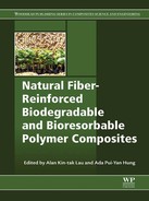
Aerogels are very lightweight and porous substrates that are made by removing liquid solvent from a gel, resulting in a solid skeleton with large pores between solid phase structures [8]. Aerogels are usually formed through some common processes such as freeze-drying and vacuum-drying. Cellulose, because of its high availability and biodegradability, is an attractive material to make aerogels from. Moreover, the ease of drying and high cross-linking ability renders cellulose ideal for aerogels [9–12]. Fig. 3.1 presents an example of a CNF aerogel made through the freeze-drying process.
For fiber-reinforced composites, it is preferred to use epoxy as a matrix for achieving high performance properties because of the higher mechanical properties of epoxy in a glassy state. Lu et al. [13] used nanocellulose treated by silane and titanate agents to show that the storage modulus of 5 wt.% CNF increased up to 3.45 GPa. Kuo et al. [14] investigated the effects of curing of epoxy in the presence of CNF. Shibata and Nikai [15] used water-soluble components with CNF during the freeze-drying process and thus created CNF preform impregnated with epoxy, which was cured at increasing temperatures to attain an elastic modulus of around 2.6 GPa at 15 wt.% nanocellulose loading. The corresponding tensile strength of about 80 MPa was obtained at 10 wt.% loading.
LCM form an important set of methods for manufacturing near net-shaped polymer composites in an inexpensive and environmentally-benign manner [16]. In LCM processes, which include resin transfer molding (RTM) and vacuum-assisted resin transfer molding (VARTM) processes, the matrix (e.g., epoxy resin) is either injected or sucked into a dry porous preform (made from reinforcement) placed in a mold. The aim is to attain full saturation of the preform with the resin so that a good bonding between fibers and resin happens in the final composite part. The polymeric resin undergoes a thermosetting reaction to cure fully and solidify after mold-filling to manufacture the desired net-shaped composite part.
3.2 How to prepare the cellulose-based aerogel preform
CNF are bio-based, biodegradable, nanoscale structures with remarkably high mechanical properties. Films cast from filtered nanofibrillated cellulose have been observed to have tensile strengths greater than 200 MPa and moduli greater than 14 GPa. Hence CNFs have a significant potential as a reinforcement for composite materials. Polymer composites made using CNF have been shown to have better mechanical properties than nonnanoscale composites [17]. However, the full reinforcing potential of these materials has not been realized because of some manufacturing issues. As mentioned earlier, a major economic reason for the hitherto limited use of CNF was that the energy required for breaking down cellulosic materials into nanofibers was prohibitively high [7]. Moreover, each repeating unit of CNF has three hydroxyl groups (Fig. 3.2) that make CNF highly hydrophilic and prone to agglomeration. This highly hydrophobic nature of CNF renders it rather inimical to good dispersion in liquids, as well as making it incompatible with hydrophobic polymers such as epoxies. Hence there is a strong demand for compatibilization of CNFs [7].

The CNF fibers are derived from wood pulp and processed into a well dispersed aqueous suspension via acid hydrolysis, TEMPO-mediated oxidation, and mechanical stress [18]. Mechanical stress and acid hydrolysis are used to break wood pulp fibers down to the nanoscale particles. Then the TEMPO-mediated oxidation process replaces some of the hydroxyl groups on a cellulose crystal with carboxyl groups superficially without changing the crystal structure or the gross fiber morphology [4]. These CNF suspensions are formed into composite preforms using the lyophilization process, where freeze-drying removes the water from cellulose after its solidification as ice and its evaporation during drying in a vacuum. The process changes ice directly from a solid to a gas, thus allowing the CNF to retain its structure during freezing. The lyophilization process consists of three separate, unique, and interdependent processes: freezing, primary drying (sublimation), and secondary drying (desorption).
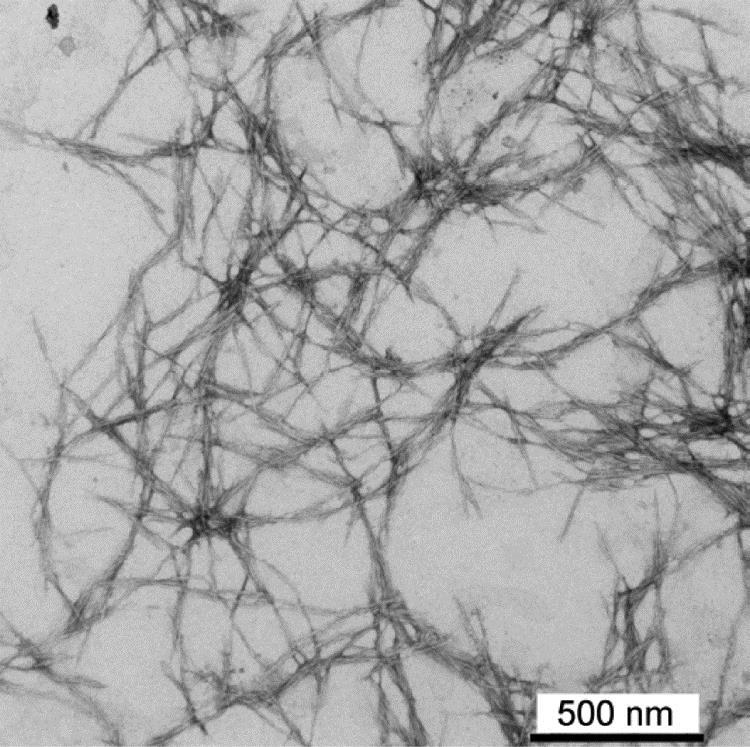
After its processing, CNF can create either randomly-oriented porous structures or highly-aligned (unidirectional) porous structures (see Figs. 3.4 and 3.5). Our research has focused on trying these structures as preforms for the LCM technology for the subsequent large-scale fabrication of isotropic and anisotropic high-strength thermoset nanocomposites.
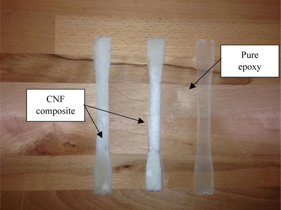
The novel unidirectional porous structures were produced using a unique directional freezing technique developed at UW-Madison (Fig. 3.3). The CNF aqueous suspension was cooled with liquid nitrogen by imposing a temperature gradient along a specific direction with the help of a metal block. This led to the formation of ice crystals along the gradient direction, and pushing of CNF solid phase into boundaries between the crystals. Once the ice crystals were formed, the unidirectionally frozen sample was put in a lyophilizer for drying via sublimation. The wettability and infusion properties of such preforms were enhanced through silane treatment, where the produced CNF samples were placed in a glass vacuum desiccator above 1 mL of trimethoxy-octadecyl silane (for each preform) and kept in a vacuum oven at 1-inch Hg pressure and 120°C for 18 h. Fig. 3.4 shows the two kinds of preforms (i.e., freeze-dried randomly-oriented and highly-aligned CNF preforms) after their removal from the mold.

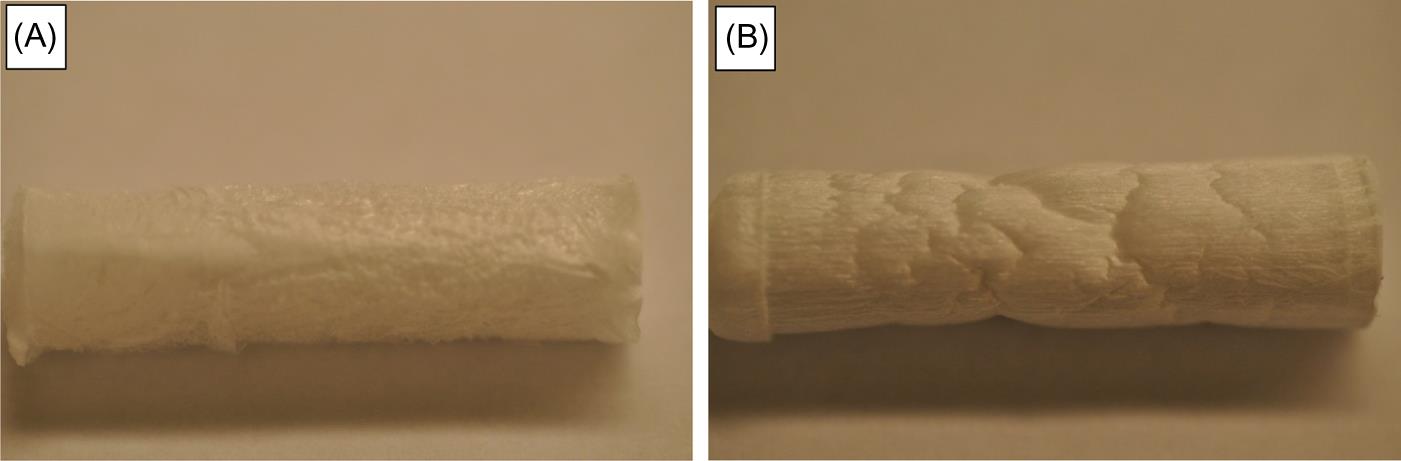
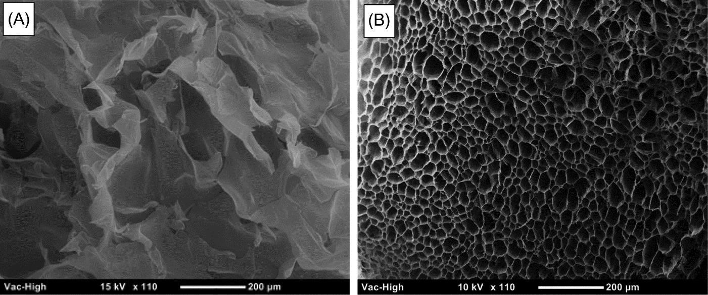
The SEM micrographs of the randomly-oriented and highly-aligned pore-spaces of the two CNF preforms are displayed in Fig. 3.5.
3.3 Making cellulose nanocomposite
Here we will describe our efforts to make a polymeric nanocomposite using CNF. The basic aim is to disperse the CNF into a polymeric matrix using the aerogel CNF preforms (unlike the dispersion of nanoparticles in a liquid through various mixing techniques used in traditional nanocomposites). The idea is that a CNF preform in the form of a porous medium has a very high surface area to volume ratio for its CNF-based solid phase, and when a composite is formed by filling all the pore space with the epoxy resin, the CNF embedded in the solid matrix will have large portions of their individual “nano” surface areas in contact with epoxy molecules, thus forming a good nanocomposite.
The CNF composite samples were made by combining the isotropic and anisotropic CNF preforms as reinforcement and the Super Sap epoxy resin (a bio-based resin with around 50% bio-content) as the matrix using an improvised micro LCM process. This resin will be referred to as bio-epoxy in this chapter. This improvised LCM process is based on the conventional RTM process where a hard mold is used for creating the final composite part. However, instead of injecting resin using a positive pressure, a negative vacuum pressure of 100 kPa pressure was applied to suck the resin through the CNF preform (Fig. 3.6). The LCM “micro” mold used in the experiments was fabricated from aluminum and polycarbonate because of the machinability and optical properties of these materials. The mold consists of an aluminum base plate with removable inserts for creating tensile and flexural test specimens. A transparent polycarbonate (lexan®) plate is screwed on top of the mold to create a leak-proof mold cavity and to act as a window to view resin movement inside the mold. Fig. 3.6 shows the experimental setup with its micro LCM mold, resin trap, and vacuum pump.

The CNF preform is laid inside the specimen cavity and the top lexan cover is screwed tight on top. A vacuum (suction) pressure of around 100 kPa is imposed at the outlet vent which is connected to the resin trap, a vessel designed to isolate and trap the overflow of any resin from the mold. The inlet vent is connected to a tube that is submerged into a beaker full of bio-epoxy+hardener mixture. The reacting thermosetting resin is then sucked upwards through the inlet tube. It then fills the inlet mold cavity, and then sweeps through the dog-bone shaped CNF preform placed in the mold. (See [19] for more details.)
Once the preform is completely wetted, the resin is allowed to cure for 24 h and the specimen is removed after resin solidification. Later the composite specimens were put in an oven for curing further (“postcure”) at 120°C for 10 min. (This process improves the mechanical behavior of CNF composites.) The specimens are then polished further using a low-impact grinding machine and a high-grit sand paper [19] (Fig. 3.7).
3.4 Mechanical, microstructural, and tribological characterization
The tension coupons prepared from CNF/bio-epoxy composite and pure bio-epoxy are tested in tension. The loading process is implemented in a displacement-controlled mode at a rate of 1.3 mm/min (0.05 in/min). During the test, the cross-head displacement and load values are recorded simultaneously. The load is applied using an electromechanical test system with a 97.8 kN (22 kip) capacity. A length of 89 mm (3.5 in) is used as a gage length in the tensile testing experiments. Note that the same test machine is used for all the specimens. Four CNF/bio-epoxy samples with fiber volume fractions ranging between 0.9 and 1.4% are tested. (The CNF aerogel specimens have typically very open and porous structures. As a result, the CNF composites made from such aerogels have very low fiber volume fractions.)
For the microstructural analysis, SEM images were obtained on a LEO 1530 FESEM with a 3 kV accelerating voltage using an in-lens detector and a working distance of 1.3 mm. The SEM micrographs were prepared from the cross-sectional areas of the tensile specimens after their fracture. For SEM imaging, the samples were gold coated for 30 s at 45 mA in a Denton Vacuum Desk V sputter coater.
Tribological behavior of the composites was investigated at ambient conditions using the pin-on-disk test (ASTM G99) under dry conditions. In the test, a stationary pin was made to slide against a rotating disk. From the fabricated composite specimens, cylindrical samples (10 mm in length, 3 mm in diameter, and with rounded contact surface) were prepared by machining. The disks were made of hardened 440 C stainless steel with a hardness of 230 HBN and an initial surface roughness (Ra) of 0.3±0.05 μm. The disk dimensions were 55 mm in diameter and 10 mm in thickness. In addition, the tribological properties were studied by varying the tribological testing parameters, such as the normal load (4, 7, and 10 N) and sliding speed (low [0.15 m/s], medium [0.25 m/s], and high [0.35 m/s]). In order to reach the steady-state friction values for each test, the sliding distance was fixed to 1 km. The linear wear loss was acquired through a linear variable differential transducer (LVDT) with an encoder, which recorded the vertical displacement of the pin. After the tests, the worn surfaces were investigated using SEM. The linear wear loss of each pin was converted into a volumetric wear loss using Eq. (3.1) derived from the geometry of a spherical cap.
(3.1)
Here h is the linear displacement (mm) in the vertical (longitudinal) axis for the pin, r is the pin radius (mm), which is assumed to be constant throughout the test, and V is the volumetric wear loss (mm3). For a given set of testing conditions, at least three repetitive tests were performed and the results of the average of three tests were presented.
3.5 Sample results obtained from mechanical, microstructural, and tribological tests
3.5.1 Mechanical properties of cellulose nanocomposite
The stress–strain diagram developed using the tensile test for the silylated and nonsilylated CNF composite samples is shown in Fig. 3.8. (The silylated sample means that the CNF sample has been subjected to the earlier-described silane treatment to enhance its wetting properties and thus insure better CNF/bio-epoxy interface.) As shown in the stress–strain diagram, the silylated CNF shows superior ultimate tensile strength and higher modules of elasticity when compared to the nonsilylated samples. In general, the CNF-reinforced specimens show a nonlinear stress–strain response that indicates lowering of the brittleness of the bio-epoxy composites due to the presence of CNF in the matrix. This could be explained by the observed formation of dry spots inside the composite at the CNF/bio-epoxy interface due to incomplete infusion of CNF preforms.

In Fig. 3.9, the stress–strain results for the anisotropic CNF composites are compared with those for the isotropic CNF composites; such results have been presented in our previous publications [19–21]. It is obvious that the modulus of elasticity and ultimate strength of the anisotropic CNF samples were increased by increasing the fiber volume fraction. Changing the pore structure from isotropic to anisotropic also caused an improvement in the mechanical properties, such that the anisotropic CNF composites displayed higher ultimate stress and modulus of elasticity compared to the isotropic CNF composites. Further alterations in the stress—strain behavior of the samples are observable in Fig. 3.9: an almost linear plot for the pure bio-epoxy samples to the increasingly nonlinear plots for the CNF composites. This nonlinearity implies that, in the presence of CNF, a toughening of the samples takes place. The nonlinearity of the anisotropic samples is more than the nonlinearity of the isotropic samples which means that the anisotropic samples are tougher compared to the isotropic ones. Higher toughness of the CNF samples could be explained by the fiber pull-out effects or the presence of fibers in the path of a crack during fracture. The honeycomb-like form and the highly-aligned structure of the solid skeleton of the anisotropic CNF could be one reason that it can deflect cracks and reduce their growth rates. All these lead to an increase in the ultimate strength and other mechanical properties of the composites.

3.5.2 Failure analysis of cellulose nanocomposites
The SEM micrographs of the fractured surfaces of the anisotropic CNF composites along with the pure bio-epoxy samples are shown in Fig. 3.10. The SEM micrographs of pure bio-epoxy show regular cracks, indicating a typical brittle fracture. On the other hand, the SEM images for the anisotropic CNF samples show a uniform fractured surface interspersed with holes or channels. The smooth part of the fractured surface indicates that the mode of failure is a cleavage similar to the brittle fracture of metals under tensile tests. Fractured surfaces clearly shows that the fibers clusters have been pulled out and the resulting channels have appeared on the fractured surface. Such fiber pull-out acts as the dominant toughening mechanism for the anisotropic CNF composites. Because of the weaker interfacial bonds between the CNF and bio-epoxy, all SEM figures show smooth surfaces on the channels. Also, the channels, being almost of the same size as the holes in the honeycomb-shaped aligned pore structure of the anisotropic CNF aerogels, are perhaps created from the “pull-out” of these individual “cylinders” of bio-epoxy.
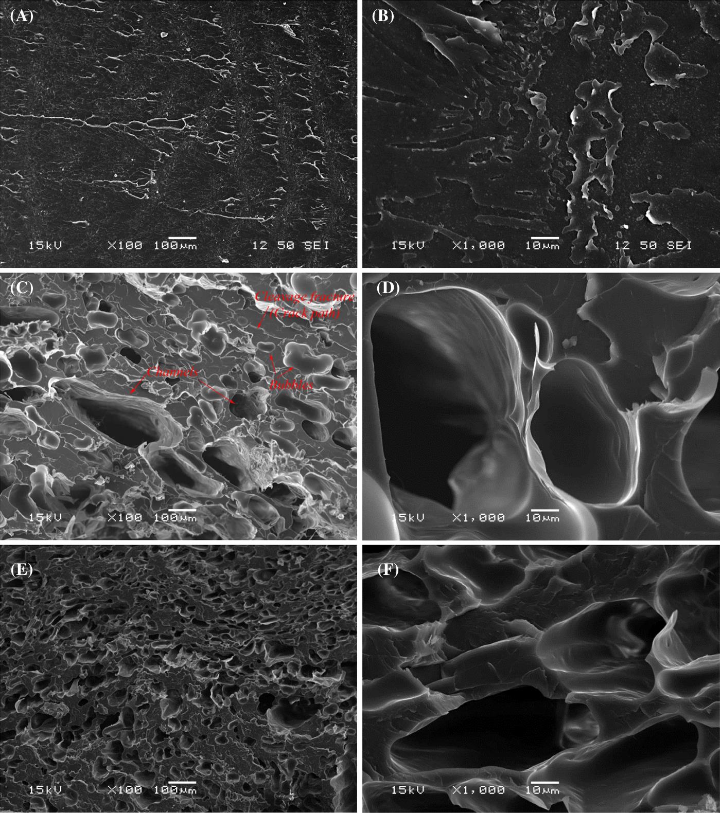
Bubbles were created in the bio-epoxy resin during its mixing prior to its infusion into the mold and also during its vacuum-induced suction through the mold. The presence of bubbles and the resulting low-interfacial bond between the CNF solid phase and bio-epoxy resin may be the reason for having a lower ultimate stress in CNF composites compared to the pure bio-epoxy.
The SEM micrographs of the fractured surfaces of the isotropic CNF composites are shown in Fig. 3.11. The silylated sample shows much less void-content compared to the nonsilylated sample—the latter displays more numerous round voids. This difference can be recognized to have come about due to the better wettability of CNF solid phase by the resin due to the silane treatment. The silane agent also improves the mechanical entanglement between the CNF reinforcement and bio-epoxy matrix because of better bonding between them during the curing process. Both these effects work together to create a better CNF composite.

3.5.3 Effect of fiber volume fraction on tribological properties
Fig. 3.12A–C show the effect of increasing CNF content in the bio-epoxy matrix on coefficient of friction (COF) at different normal loads and sliding speeds. In the figures, the connecting data points refer to the average values of the three independent tests while error bars show the corresponding scatter. Fig. 3.12A shows the variation in COF with increasing volume fractions of nanocellulose in the bio-epoxy matrix at 4, 7, and 10 N for a sliding speed of 0.15 m/s. It is clear that the COF decreases with increasing volume fraction of nanocellulose in the bio-epoxy for all the three normal loads during the low sliding speed of 0.15 m/s. Also, the reduction in COF is higher at larger normal loads. It is also obvious that the reduction in friction is more significant when the volume fraction of nanocellulose is increased from 0 to 0.9% than from 0.9 to 1.4%. It can be concluded from Fig. 3.12A that the bio-epoxy sample showed better tribological performance at lower normal loads and the 1.4% CNF composite showed enhanced tribological performance at higher normal loads due to the presence of nanocellulose on contact surfaces.

Fig. 3.12B shows the variation of COF with volume fraction of nanocellulose in the bio-epoxy matrix at 4, 7, and 10 N when the tests were performed for a constant sliding speed of 0.25 m/s. Similar to the 0.15 m/s observations, the COF decreases when 0.9% volume fraction of CNF was added to the bio-epoxy for all the three normal loads. However, the COF increases for 4 and 7 N when 1.4% CNF added to the bio-epoxy matrix, although they have lower COF than the pure bio-epoxy. Also, for 10 N, the COF constantly decreases although the reduction in COF is less significant. Incidentally, the 10 N load led to the lowest COF. In addition, the pure bio-epoxy showed better tribological performance at lower normal loads, while the 1.4% CNF composite showed superior tribological performance at higher normal loads.
Fig. 3.12C displays the variation of COF with increasing volume fraction of nanocellulose in the bio-epoxy matrix at 4, 7, and 10 N for a constant sliding speed of 0.35 m/s. At this higher sliding speed, the variation of COF with the volume fraction of CNF showed totally different trends. At 4 N normal load, the COF increases when 0.9% volume fraction of nanocellulose is added to the bio-epoxy matrix; later the COF decreases slightly when the fiber volume fraction is raised to 1.4%. The COF was found to be the lowest for the pure bio-epoxy as compared to the nanocellulose composites. For the 7 N normal load, the COF does not change much with the increasing nanocellulose volume fraction. Interestingly, at the highest normal load of 10 N, the COF decreases with the increasing volume fraction of nanocellulose for the 0.15 and 0.25 m/s sliding speeds. From the above results, it can be concluded that pure bio-epoxy has poor tribological properties and is preferable only for low load and low sliding speed applications. However, for more severe tribological conditions, a higher volume fraction of nanocellulose would be preferred in the CNF composites.
Fig. 3.12D–F show the variation in wear rate (volume loss) with increasing volume fractions of CNF in the bio-epoxy matrix for various normal loads (4, 7, and 10 N) at sliding speeds of 0.15, 0.25, and 0.35 m/s, respectively. It can be observed that for a given volume fraction, the wear rate increases with the increasing normal load for all sliding speeds. The wear rate decreases with the increasing fiber volume fraction of the cellulose in the bio-epoxy matrix. In addition, the wear rate decreases with the increasing sliding speed. The volume loss in nanocellulose/bio-epoxy composites is significantly less than that in the neat bio-epoxy. This is because the incorporation of nanocellulose in the bio-epoxy matrix effectively improves the mechanical and tribological properties of bio-epoxy due to the enhancement in strength properties as shown in Fig. 3.8 and the ability of nanocellulose fibers to resist the bending force as reported in the literature [22]. Although, the hardness of the material has long been observed as a primary material property that expresses the wear resistance, there are strong evidences to suggest that the elastic modulus can also have an important influence on the wear behavior [23]. Therefore, the bio-epoxy matrix reinforced by 1.4% CNFs have better wear properties owing to higher elastic modulus as shown in Fig. 3.8. In addition, the cellulose fibers play a major role in improving the fracture toughness of polymer matrix through several energy absorbing mechanisms, such as fiber pull-out, fiber fracture, and fiber bridging [24]. These mechanical factors seem to have significant effects on the tribological properties of nanocellulose/bio-epoxy composites as well. Also, the addition of nanocellulose into bio-epoxy results in an improvement in the COF and reduction in the volume loss of nanocomposites. In general, as demonstrated in Fig. 3.12D–F, superior improvement in wear rate occurred at the highest volume fraction of CNFs due to the increase in stress transferred to the fiber and the ability of cellulose fibers to resist the bending forces [25], to carry the higher load, and to support the bio-epoxy matrix. Table 3.1 displays quantitatively the improvements in COF and wear rate of the CNFs reinforced composites.
Table 3.1
Summary of improvements in the COF and wear rate of CNF/bio-epoxy composites
| Sliding speed (m/s) | Load (N) | CNFs volume fraction | |||
| 0.9% | 1.4% | 0.9% | 1.4% | ||
| COF improvement (%) | Volume loss improvement (%) | ||||
| 0.15 | 4 | 6.0 | 19.4 | 73.8 | 82.5 |
| 7 | 25.4 | 31.0 | 71.7 | 72.6 | |
| 10 | 50.0 | 55.1 | 67.5 | 71.6 | |
| 0.25 | 4 | 8.2 | −10.2 | 21.9 | 67.9 |
| 7 | 27.8 | 9.3 | 25.0 | 70.2 | |
| 10 | 41.7 | 45.0 | 4.5 | 57.4 | |
| 0.35 | 4 | −27.5 | −20.0 | 25.6 | 66.9 |
| 7 | 2.2 | 0.0 | 31.3 | 65.8 | |
| 10 | 28.8 | 34.6 | 16.5 | 43.6 | |

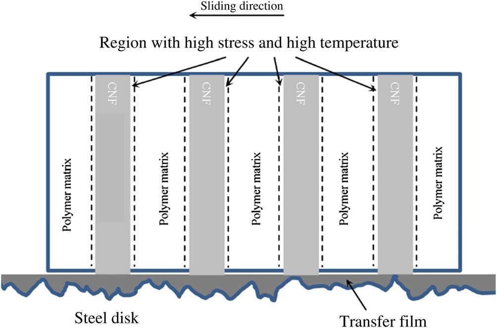
Fig. 3.13 presents a schematic illustration of the wear mechanisms dominant during sliding wear of the bio-epoxy composites reinforced by nanocellulose. The continuous transfer film formed during the running-in stage can effectively reduce the direct contact of the composite with the asperities of hard metallic counterface [26,27]. During the sliding process, the CNFs reinforcement may carry most of the contact load and hence may wear against the counterface. In addition, thermal–mechanical failure of the material in this contact region may take place due to high local friction and heating [28]. In such a situation, the polymeric matrix in the interfacial region around CNF solid phase suffers higher stress and temperature. As a result, the CNF solid phase will be removed more easily, which is associated with a progressive increase in the wear rate of the composites. Therefore, the detached CNF solid phase can fill the gap between the asperities and reduce the roughness of the counterpart surface, and consequently decrease the COF and volume loss.
To understand the effect nanocellulose fibers on the wear mechanism, two composite samples with different nanocellulose fiber volume fractions and a neat bio-epoxy sample were chosen for comparison. The worn surfaces were further studied using stereo-macroscopy and SEM. The texture of worn surfaces clearly depicts the composition-dependent wear behavior. All selected coupons were compared for the same normal load and sliding speed. The surface damage on the worn surface is found to decrease with an increase in the nanocellulose content interspersed with the bio-epoxy matrix. This reduced the wear-volume loss and hence the nanocomposites displayed improved wear resistance when compared with the neat bio-epoxy materials (since no CNF solid phase was there to reinforce the matrix of the latter). Hence, the load-bearing ability of cellulose in the bio-epoxy matrix is an important reason for the better wear resistance of the composites. Furthermore, by increasing the CNF content, more fibers can bear the load which tends to decrease the wear rate at higher volume fractions of CNF. The SEM image of the worn surface of neat bio-epoxy showed more debris and fine cutting chips similar to those produced during machining. It implies that the wear mechanism for the neat bio-epoxy sample is abrasive. The detached debris act as third body abrasives. These debris can further increase the depth of the grooves by ploughing action and the material is continually displaced sideways to form ridges adjacent to the developing grooves by plastic deformation. In addition, the debris can cut the surface in a way similar to micromachining and all the material displaced by the debris is removed as a chip. Consequently, the volume loss increases in neat bio-epoxy as confirmed by the experimental results presented.
In contrast, a minimal amount of debris can be seen on the surface of 0.9% CNF/bio-epoxy composite and no debris are found on the surface of 1.4% CNF/bio-epoxy composite. Therefore, the composites showed lower wear-rates. The SEM image of the worn surfaces show that the dominant wear mechanism for the composites is adhesion due to plastic deformation and transfer layer is seen in some regions on the composite surfaces. A peculiar feature of this wear process is the back transfer of material from one surface to another where iron from steel is transferred to the polymer surface [29]. A similar observation is reported in the literature where a soft aluminum material slides against a hard steel counter material and iron from the steel counter material is transferred to the soft aluminum sample surface [30,31]. This phenomena occurs due to the localized bonding between the contacting solid surfaces [26]. Because of the presence of some debris on the worn surface of 0.9% CNF/bio-epoxy composite, the wear mechanism for this composite is a combination of abrasion and adhesion with the latter being dominant. On the other hand, the wear mechanism of 1.4% CNF/bio-epoxy composite is completely adhesive in nature.
By investigating the worn surfaces, it is clear that the surfaces of the composites are smoother than that of the neat bio-epoxy. The smooth surfaces imply that the lower wear-rates are prevalent for the composites. The 3D images of the worn surfaces (Fig. 3.14) confirm that the surface of composites are less coarse with the roughness parameter, the maximum heights of the profile (Rt), being 37.3, 22.9, and 21.6 μm for the neat bio-epoxy, 0.9% CNF/bio-epoxy, and 1.4% CNF/bio-epoxy, respectively. Generally, once the nanocellulose fibers were incorporated in the bio-epoxy matrix, the worn surfaces appear much smoother even at severe wear conditions (at the highest normal load and sliding speed) in comparison with the neat bio-epoxy without nanofibers.
