As with many areas of human endeavor, the gap that separates the theory and practice of NMS development is very wide. Viewed against the backdrop of rapidly evolving networks and increasingly sophisticated end-user requirements, the problems facing the vendors of NMS products are considerable. Not least is the simple problem of scale in the management plane: Emerging NEs are big, dense, and complex, incorporating a growing range of technologies. In this final chapter, we try to draw together the main threads running through the book and revisit some of them now that our foundation chapters are complete. The discussion covers the following main areas:
MIBs—how careful design can greatly assist management (
nextFreeIndex, single table on originating node, and default values).MIBs and scalability—the size of emerging NEs may generate a need for some form of compressed MIB data.
Decision-making in the network—pushing more decisions out of the NMS and into the network. We examine the MPLS FTN MIB to see an example of this; also, Policy-Based Network Management (PBNM) is useful in this context.
Generic objects realized using software abstraction.
The increasing need for end-to-end security.
Shrink-wrapped solutions or consultancy buy-in.
The roles of QA, IT, and developers.
Facilitating a solution mindset.
We start with yet another MIB-related detour: The issue of storing policies in MIBs is introduced, followed by a description of intercolumn relationships.
In Chapter 8, “Case Study: MPLS Network Management,” we studied in some depth the structure and use of two of the IETF MPLS MIBs. These MIBs have been well-designed; for example, a signaled traffic-engineered tunnel created using the mplsTunnelTable can be managed with reference just to the originating node MIB. In other words, it is not necessary to browse every node in the path of the tunnel, because the necessary details are stored in the originating node. This helps improve the manageability and scalability of the MPLS network. In effect, the NMS can manage such tunnels via the LERs in an MPLS network. This has other benefits: LERs are often more powerful devices than the LSRs in the core of the network, so they are potentially more able to withstand large bursts of management plane traffic, for instance, when the tunnels are being discovered. Another important point is that the path taken by the tunnels through the network is also stored in the LER in the (optional) mplsTunnelARHopTable. If this table is supported, then the originating node knows the path. This again avoids the need for delving into the transit LSR MIBs.
All of the MIBs we've studied so far have been essentially passive in nature; that is, they serve to record details of the managed network. There is another use that can be made of a MIB: policy storage. In this, the MIB is used to store rules and actions. Policies consist of conditions (or rules) and actions that should be taken when the conditions are met. Later in this chapter, we study the FTN MIB because it provides a framework for storing policies that can be used to manage IP traffic as it enters an MPLS network.
An important area of MIB design is that of intercolumn dependency in which the value of column X provides a context for column Y, or vice versa. An example is where a tunnel instance is a backup for a primary tunnel as illustrated in Figure 9-1.

In Figure 9-1, we see an MPLS network with two tunnels. One is a primary and the other is a backup. This can be brought about by creating two entries in the mplsTunnelTable, one of which is an instance of the other. By instance, we mean a copy in all things except the path taken. The two tunnels can be configured to share the same set of resources, such as bandwidth, or they can each duplicate the resources. The primary tunnel follows the path {LER1, LSR1, LSR2, LER2}, while the backup follows the path: {LER1, LSR3, LSR4, LER2}. In Figure 9-1, we also see an excerpt from the mplsTunnelTable in LER1. The primary tunnel has the value 1 in both mplsTunnelIndex and mplsTunnelInstance. In other words, it is the first entry in the mplsTunnelTable and is not an instance of another tunnel (i.e., it is an instance of itself). The backup tunnel, however, has the value 1 in mplsTunnelIndex and 2 in mplsTunnelInstance. This means that it occupies the second entry in the mplsTunnelTable and is an instance of mplsTunnelIndex 1. In other words, it is a backup instance of the primary tunnel.
Let's consider the steps that must be taken to bring this about using SNMP. To create the primary tunnel, we set the values of mplsTunnelIndex and mplsTunnelInstance both to 1 (as well as setting other mandatory columns, as was seen in Chapter 8). It is likely that we will have looked up the value of the mplsTunnelIndexNext object to get the next free mplsTunnelTable index. To create the backup tunnel, we must consult the MIB (or an external database) for the value of mplsTunnelIndex that corresponds to the primary tunnel—in this case, 1. We then create another entry in mplsTunnelTable with the mplsTunnelIndex and mplsTunnelInstance values 1 and 2, respectively.
So, the value of mplsTunnelInstance serves to indicate if the tunnel is an instance of another tunnel. If two (or more) rows in the tunnel table have the same value of mplsTunnelIndex and different values of mplsTunnelInstance, then they are instances of each other. The tunnel instances can act as backups to each other, or they can load-share incoming traffic.
This is an example of intercolumn dependencies in which the value of one column depends on the value of another. In the case of backup (or load-sharing) tunnels, the value of mplsTunnelIndex has the same value as mplsTunnelIndex from another row in the mplsTunnelTable. The two entries are differentiated by the value of mplsTunnelInstance. Such dependencies contribute some complexity to the MIB. For example, should we be allowed to delete a primary tunnel before deleting the backup? Usually not, because the backup generally exists only to protect the primary tunnel. So, the agent on LER1 should enforce this, and the NMS should follow suit.
As with many engineering decisions, the best way to implement this is with clear rules, such as precluding deletion of a primary tunnel until all instances have been deleted. The agent should enforce these rules along with the NMS (e.g., if the user attempts to delete a primary tunnel before deleting the backup). It is a bad practice for the NMS to rely on the agent to enforce such rules—the agent may erroneously permit inconsistencies. For this reason, it is better for the NMS to infer relationships like tunnel instances and enforce rules concerning the order of deletion without relying on the agent.
Another important issue is that of providing default values for MIB objects. This can have an important impact on the complexity of the SNMP-handling software in an NMS, as we'll see in the next section.
If two MIB columns depend semantically on each other, then it is good practice to have default values via the DEFVAL clause. To illustrate, let's assume we have a MIB where two columns, X and Y, have a relationship with each other. Let's say X has no default value and can take the values 1 and 2, but these have meaning only if Y has a nonzero value. In other words, if Y has the value zero, then we should not set any value in X. This is a bad MIB design for a few reasons:
The correct value of X is undefined if Y is zero.
SNMP-handling software code in the NMS must check the value of Y before setting X.
Not setting the value of X (e.g., when Y is zero) may give rise to holes in the MIB.
Having to check the value of an object makes the SNMP code unnecessarily complex. It makes flow-through operations more difficult to achieve because the incoming data has to be validated—this should already have occurred at the user interface layer. It also introduces special cases into the NMS software. If such intercolumn relationships are necessary, then it should be possible to use default values in the MIB object definition via the DEFVAL clause. Once this is done, the values of X and Y are irrelevant to the SNMP (provisioning) code: It simply sets the values passed to it regardless of whether or not they are defaults. This is so because the values will either be defaults or valid settings.
The issue of holes is important. These can arise if a SET operation is completed on a table row without setting all the columns. It is up to the agent to provide some default value if it deems it necessary. The problem with MIB holes (as we saw in Chapter 6, “Network Management Software Components”) is that a getRequest on a MIB hole can result in an exception; likewise a getNextRequest on a MIB hole results in getting the lexical successor to the specified object skipping any holes. This can result in unexpected data being presented to the NMS. Providing default values can also help in avoiding MIB holes. When holes are avoided, it becomes easier to navigate around a MIB.
An allied problem occurs in the use of relational database products (e.g., Informix, SQL Server) when null values have been written into tables. Retrieving such null data using Java can result in exceptions being thrown. This can be highly inconvenient because it then becomes necessary to catch such exceptions.
An added difficulty is that exception handling in languages such as Java can be quite slow. Just as for MIBs, it is generally better practice to avoid the problem altogether by the use of default (i.e., not null) schema values in the table definitions.
The crucial role played by MIBs in network management has been stated many times. MIBs are in fact so crucial that they can greatly simplify both the structure of the NMS and the ease with which the network can be managed.
The scale of emerging NEs is such that SNMP may be approaching a physical limit—navigating tables with millions of entries is almost certainly not a practical proposition. MIB designs must incorporate this trend and allow for possible techniques such as data compression. Compressed PDUs could use standard data compression techniques (e.g., LZ77) in order to manipulate larger amounts of data. In effect, larger PDUs could be used because each field could be compressed. On the downside, this would complicate PDU handling and make for slower NE responses because of compression overhead. A more permanent solution to this is to push more management decision-making capability into the NEs themselves, as discussed in the next section.
The mapping of IP packets into the MPLS domain is a nontrivial task. The increasingly high speed and volume of IP packet feeds across enterprise networks is a compelling reason for moving individual packet-handling decisions outside of the NMS. Yet another important MPLS MIB—the FTN MIB [IETF-MPLS-FTN]—provides a framework for this and is now described.
The full title of this MIB is a little unwieldy: MPLS FEC-To-NHLFE Management Information Base. An understanding of this MIB should help us gain a deeper appreciation of the MPLS examples described in Chapter 8. It will also illustrate a way of storing policies in MIBs. These policies are created by the NMS user and executed by the NE (usually in conjunction with special-purpose network hardware). Before starting to describe the MIB, we define the term Forwarding Equivalence Class (FEC).
A FEC is a group of IP packets that receive the same forwarding treatment. A FEC dictates that packets follow the same path through the network and experience a defined quality of service. A FEC might correspond to a destination IP subnet or address prefix (e.g., 10.81/16), but it also might correspond to any traffic class that a given Edge-LSR (or LER) considers significant. For example, all traffic to a given destination with a certain value of IP DS field might constitute a FEC.
An analogy for a FEC is international immigration in an airport. Non-nationals are separated out from nationals by the passport they hold. Two queues are formed, one for nationals and another for non-nationals. The nationals queue is usually much faster than the one for the non-nationals. In this case, the FEC is dictated by passport and the forwarding behavior is much faster for nationals, that is, a faster queue. A conceptually similar mechanism exists at the point of ingress to an MPLS network.
At the point of ingress to an MPLS network, packets are assigned to a forwarding equivalence class or FEC. A FEC is a group of IP packets that are forwarded in the same manner, that is, over the same path, and with the same traffic-handling treatment. In conventional IP routing, FEC assignment occurs at each hop; in MPLS it occurs just once at the ingress. Once a packet has been assigned to a FEC, it is labeled. The labeled packet is then ready for MPLS forwarding.
Once an IP packet has been labeled, the MPLS node must decide where to send (or forward) it. The next hop label forwarding entry (NHLFE) is used for this purpose and contains the following details:
The next hop for the packet—an LSP or a tunnel
The operation to be performed on the label stack
Recall from Chapter 8 that an LSP is an object created using the LSR (and TE) MIB. MPLS-encoded packets pushed onto an LSP then follow the path associated with that LSP. Similarly, the next hop can be a traffic-engineered tunnel (created using our old friend, the MPLS tunnel table MIB). The label stack operation can be one of the following:
Replace the label at the top of the label stack with a specified new label.
Pop the label stack.
Replace the label at the top of the label stack with a specified new label, and then push one or more specified new labels onto the stack.
When a packet matches a particular rule, a corresponding action is executed, such as forwarding or discarding it. Other actions are possible, such as modifying the DS field (in a process called remarking) or redirection of the packet to a specific outgoing interface.
The next part of the FTN MIB concerns the association between the packet-handling rules and specific NE interfaces. The last table in the MIB provides performance-related statistics—useful for checking the speed of packet handling, throughput, and so on.
This is the broad functional description of the FTN MIB; we now look at the details of the following three tables:
mplsFTNTable
mplsFTNMapTable
mplsFTNPerfTable
The mplsFTNTable is used to store mappings between FECs and NHLFE. Each row defines a rule to apply to incoming IP packets and an action to take if the rule applies. The criteria for rule construction can consist of the following objects:
Source IP address (version 4 or 6)
Destination IP address (version 4 or 6)
Source port
Destination port
DS value
These are all fields in the IP packet header, as we saw in Chapter 3, “The Network Management Problem,” Figure 3-5. Another object, called the action pointer, serves to point at an entry in either the LSR MIB (mplsXCEntry) or the TE MIB (mplsTunnelEntry).
The mplsFTNMapTable is used to activate or map FTN entries defined in mplsFTNTable to specific interfaces. FTN entries are compared with incoming packets in the order in which they are applied on an interface. The mplsFTNMapTable supports a linked-list structure of FTN entries. The order of this list dictates the order of application of the associated policies on a given interface. So, if two FTNs, ftn1 and ftn2, are associated with an interface, then IP packets are processed against the settings in ftn1 and then ftn2.
Finally, the mplsFTNPerfTable provides performance counters for each FTN entry on a per-interface basis. Because LERs are located at the boundary of IP and MPLS networks, the traffic levels can be very high (e.g., an SP boundary connected to a large corporate site), so there is a need for high-capacity counters in order to avoid 32-bit counters wrapping around (although wraparound is clearly still possible).
This example illustrates the FTN MIB setup required for pushing MPLS-encoded IP traffic into either an LSP or a tunnel. Figure 9-2 illustrates two IP traffic streams feeding into an MPLS LER (Edge Router 1). One IP source is sending voice-over-IP (VoIP) telephony traffic, and the other is SMTP (email distribution). We want to push the SMTP traffic through the LSP and the VoIP traffic through the tunnel. The VoIP traffic has real-time requirements, so let's assume that we have created the tunnel with adequate bandwidth and an appropriate assigned QoS (as we saw in Chapter 8). The SMTP traffic requirements are less stringent, so we use an LSP for this purpose, with no bandwidth resource allocation and a best-effort QoS. The tunnel, however, has to carry real-time telephony data, so we assume that the tunnel has dedicated resources (e.g., 640kbps as we saw in Chapter 8).

The LSP and tunnel are capable of transferring MPLS-encapsulated IP packets through the core network and delivering them as IP at the point of egress (Edge Router 2).
In this case, we have two IP destinations: the SMTP Gateway at IP address 10.81.1.131 and a VoIP Gateway at 10.81.1.132, respectively. The setup we illustrate in Figure 9-2 is unidirectional (a telephony application would require bidirectional connections); to complete the VoIP picture, we would need another tunnel (or LSP) to forward traffic in the opposite direction.
As can be seen in Figure 9-2, the egress MPLS label used by the core router has the reserved value 0. This value is called Explicit Null and is used in order to indicate to the next MPLS node (Edge Router 2) that the MPLS data must be stripped off the packet and a normal IP lookup performed. In other words, the label value of 0 tells the next node that the packet must be returned to the IP domain. The following example illustrates how the different IP traffic types are pushed into either the LSP or tunnel.
In order to push IP traffic into the LSP in Figure 9-2, an entry is required in the mplsFTNTable. The LSP setup requires the network administrator to know in advance the values of the following objects at each hop:
Figure 9-2 illustrates the MIB objects needed for setting up the mplsFTNTable. These objects are required only for Edge Router 1 and consist of the following:
The incoming label is not applicable because IP traffic lands at the ingress interface (and hence has no attached MPLS label)
Egress interface index value of 6 (interface A)
Egress label value of 30
Given these details, we now have enough information to populate a row in mplsFTNTable:
{ mplsFTNIndex = 1,
  mplsFTNDescr = "FTN-ENTRY-1 for IP subnet 10.81.0.0",
  mplsFTNMask = 0x01, -- Look up destination address only
  mplsFTNAddrType = ipv4,
  mplsFTNDestIpv4AddrMin = 10.81.1.131,
  mplsFTNDestIpv4AddrMax = 10.81.1.131,
  mplsFTNActionType = redirectLsp,
  mplsFTNActionPointer = mplsXCLspId.5.0.0.3 }
The value of mplsFTNActionPointer indicates the LSP to which packets should be redirected. It is set to point to the first column object of the XC entry that corresponds to this LSP. This is mplsXCIndex.5.0.0.3, which represents the following mplsXCTable entry:
{ mplsXCIndex = 5,
  mplsInSegmentIfIndex = 0, -- originating LSP
  mplsInSegmentLabel = 0, -- originating LSP
  mplsOutSegmentIndex = 3, -- pointer to a row in mplsOutSegmentTable
  mplsXCLabelStackIndex = 0 }
This mplsXCTable entry in turn points to the following row in the mplsOutSegmentTable:
{ mplsOutSegmentIndex = 3,
  mplsOutSegmentIfIndex = 6,
  mplsOutSegmentPushTopLabel = true,
  mplsOutSegmentTopLabel = 30 -- Egress label value }
As can be seen, the values in mplsOutSegmentTable match those illustrated in Figure 9-2. Finally, we have mplsFTNMapTable, which activates the FTN entry:
{ mplsFTNMapIfIndex = 1,
  mplsFTNPrevIndex = 0, -- The first FTN entry on this interface
  mplsFTNMapCurrIndex = 1 }
IP packets with the destination address 10.81.1.131 are now redirected into the LSP as required.
In order to push IP traffic into the Tunnel in Figure 9-2, another entry is required in the mplsFTNTable. We give this row the index value 2.
{ mplsFTNIndex = 2,
  mplsFTNDescr = "FTN-ENTRY-2 for IP subnet 10.81.0.0",
  mplsFTNMask = 0x01, -- Look up destination address only
  mplsFTNAddrType = ipv4,
  mplsFTNDestIpv4AddrMin = 10.81.1.132,
  mplsFTNDestIpv4AddrMax = 10.81.1.132,
  mplsFTNActionType = redirectTunnel,
  -- We assume that the ingress and egress LSR IDs are 1.1.1.1 and
  -- 2.2.2.2 respectively for this tunnel as seen in Figure 9–2
  mplsFTNActionPointer = mplsTunnelIndex.4.0.1.1.1.1.2.2.2.2 }
In mplsTunnelTable, we have the following row with index 4:
{ mplsTunnelIndex = 4,
  mplsTunnelInstance = 0, -- primary tunnel
  mplsTunnelIngressLSRID = 1.1.1.1,
  mplsTunnelEgressLSRID = 2.2.2.2 }
Finally, we have mplsFTNMapTable, which activates the FTN entry:
{ mplsFTNMapIfIndex = 1,
  mplsFTNPrevIndex = 1,
  mplsFTNMapCurrIndex = 2 }
IP packets with the destination address 10.81.1.132 are now redirected into the traffic-engineered tunnel as required.
In many ways the present generation of NMS (i.e., NMS/EMS and SNMP entities/agents) exhibit some similarity to the problems attached to the automation and control of manufacturing systems in the 1980s and 1990s. The paucity of local intelligence in manufacturing systems put a great strain on centralized management and control systems, and the need for distributed intelligence was compelling.
One solution to those problems was to use local intelligence in networked controllers (similar to SNMP agents). The latter would then use local sensors and low-cost processing power wherever it was needed rather than in a central location. These distributed controllers then only reported serious problems back to a central supervisory management system. This arrangement freed the central management system to perform more complex (and centralized) calculations, such as scheduling production runs and reporting on scrap.
It is increasingly likely that a similar approach will be needed for NMS, that is, more and more agent intelligence. PBNM provides a basis for this by allowing for NEs to take some control responsibility. The FTN MIB provides an SNMP-based example of policy usage.
The FTN MIB provides an SNMP-based example of policy usage. Other types of decision-making can be pushed into the network. One area is that of billing and accounting. Many service providers use a flat-rate billing model because the deployed NEs and management facilities cannot provide a usage-based approach. Usage-based billing allows for improved SP margins and network resource use. The Lightweight Flow Accounting Protocol (LFAP) from Riverstone is an effort to provide for more accurate billing and accounting in the NEs themselves. This is similar to the provision of CDR/PDR facilities that we saw in Chapter 6. The merit of LFAP is that it may become a standard.
Over time, we may expect to see more of the FCAPS being standardized and implemented in NEs. This would free the NMS/OSS to do very advanced functions, such as:
In other words, as FCAPS capability is pushed into the network (along with policy-based facilities), we may see some OSS (or possibly business management system) facilities being pushed in turn into the NMS.
Throughout this book, we have seen a range of aggregate objects, including VPNs, VLANs, and LSPs. Aggregate objects combine base-level components to create some type of higher level service. An example is an NE that supports IEEE 802.1Q-based VLANs. Such an NE facilitates the creation of VLANs that span more than one device. In other words, several components in the network combine together into an aggregate object that provides a network-level service (in this case, a VLAN). Service providers now offer layer 3 VPNs (e.g., based on RFC 2547) as a revenue-generating service to corporate customers.
Managing these complex services is a major challenge, and doing so in a scalable fashion remains one of the biggest problems faced by the industry. It is possible that new MIBs will be needed to represent these aggregate objects, and realizing them in the network may well require new signaling protocols. An example scenario might be when a service provider wants to add a customer site to a VPN. The steps might include the following:
Create a virtual circuit (e.g., MPLS, ATM, and FR) from the CPE to a PE router.
Map the traffic on this circuit to an MPLS core.
Map the QoS characteristics of the incoming traffic to the provide core.
Ensure that this traffic goes to a specified set of destinations inside the VPN.
Finally, before creating the service, ensure that encryption/authentication is in place.
The NMS will almost certainly be called upon to provide this type of multitechnology solution.
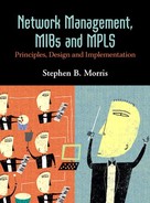
The increasing mix of technologies deployed in enterprise networks places a growing burden on NMS. The software components used to realize NMS must become increasingly abstract. This needs to occur at all levels of the software, with technology specifics cleanly separated in their own layers. So, when application code needs access to NEs via SNMP, all calls should be made to separate code. In other words, business logic should not be mixed with network device technology access code. The simple structure illustrated in Figure 9-3 provides an idea of this demarcation.
All code written to access specific technology should also be as generic as possible; for example, it is better to name a class method (assuming the code is written in C++ or Java) getLabelValue() than getMPLSLabelValue() because the former can be used for a number of label-based technologies, such as ATM, MPLS, FR, and Pseudo-Wires, whereas the latter is tied to MPLS. In a similar vein, code used to create virtual connections should use naming conventions such as createConnection() rather than createFrameRelayConnection(). The latter is again tied to one technology, whereas the former is more flexible and can be extended to support other technology types as they arise. Parameters in these function calls (or Java methods) can be used to distinguish the underlying technology types. So, we might have a top-level provisioning code method (with an abbreviated parameter list), such as:
createConnection(int technologyType, addressType sourceAddr, addressType destAddr, ...)
Internal to createConnection(), we can distinguish between the technologies using the technologyType parameter. The value of this parameter is then passed to another (technology-specific) method that actually creates the required low-level virtual connection using a Java switch statement as follows:
switch (technologyType)
{
case (ATM_SPVX)
createATMConnection(ATM_SPVX, sourceAddr, destAddr, ...);
break;
case (FRAME_RELAY_PVX)
createFrameRelayConnection (FRAME_RELAY_PVX, sourceAddr, destAddr, ...);
break;
case (MPLS_LSP)
createMPLSConnection (MPLS_LSP, sourceAddr, destAddr, ...);
break;
case (MPLS_TE_TUNNEL)
createMPLSConnection (MPLS_TE_TUNNEL, sourceAddr, destAddr, ...);
break;
}
The key point is generic outer code. We get specific about technology only at a well-defined point in the code rather than mix in potentially many different technology types at an early stage. An added bonus of this is that subsequent changes required to one of the low-level methods, such as createMPLSConnection(), do not have any effect on the other methods (such as the ones for Frame Relay or ATM).
The international terrorist threat has had a significant effect on the area of network management. The need for security is now paramount (along with the need for disaster recovery planning and service survivability). Security is needed at every level of a network, from the NE and subtended (i.e., attached) equipment all the way up to the NMS server and client machines. This can be called end-to-end security, the purpose of which is to protect the network and its data from unauthorized access. Connecting to an NE EMS should employ authentication and encryption, making certain that little or no clear text is exchanged. The same holds true for exchanges between an NMS and EMS, OSS and NMS, and so on.
One of the consequences of globalization is a greater degree of skills specialization and homogeneity of products. In modern corporations, it is increasingly easy to relocate and move between different host countries, often working in the same (or a similar) job and for the same organization. This means that software development skill sets can be used to move fairly easily between different geographical locations. In other words, software developers can become quite specialized. In a similar fashion, the vast range of commercially available NMS products share a great many functional characteristics. So, we see a great many products competing for a finite number of customers. Software developers with broadly similar skill sets create these products. Increasingly specialized software development skill sets may have a downside. This is particularly the case as the number of developers in vendor organizations is reduced. Those developers who remain may not have a broad enough vision for effectively creating NMS products.
Even without reduction in numbers, skill set specialization also has its own problems when adopting solution engineering, such as:
Not taking an end-to-end or customer-type system view—for example, a developer creates a Frame Relay virtual circuit, verifying that the data is written to the database but not the network (a customer generally sees the network as the true database and is more interested in verifying that the connection is created in the network).
Not taking consideration of a feature beyond the current release cycle.
Also, NMS products (and NEs) are increasingly homogeneous, often offering base-level features such as fault and performance management. Many vendor (and system integrator) organizations make sizeable sums of money in selling consultancy to network operators. This consultancy is often geared toward assisting a network operator in incorporating a given NMS product into its workflows and business processes. In effect, if consultancy is offered as part of a product sale, then the vendor is trying to add differentiation in this way. This seems a cumbersome and very expensive approach, given the relative ease with which modern software tools can be used to create highly useable software.
A better deployment model results if NMS products are well-designed with characteristics such as:
High-quality (or standard) MIBs
Generic software components, such as GUIs that allow the management of generic connections rather than technology-specific objects, whether they be optical light paths or Frame Relay virtual circuits
Flow-through provisioning features with thin software layers
Adherence to standard NBIs (discussed in the next section)
We believe that products fulfilling these requirements have a much better chance of fitting into enterprise networks, workflows, and business processes, and standing on their own merits. In other words, incorporating such products into large enterprise networks should not be such a daunting and expensive task as is perhaps the case at present.
Communication between the OSS and NMS is crucial to the successful management of large SP networks. In the same way as NMS needs to communicate with EMS, the OSS needs to be able to communicate with the NMS. The latter is facilitated using the NBI. Broadly speaking, there are two ways of implementing an NBI layer:
Put software in the OSS layer
Put software in the NMS
A recurring theme in this book is the need to keep software layers as thin as possible. This applies to all layers, including the section of the OSS that interacts with the NMS. To this end, the ideal arrangement is for the NMS and OSS to use the same code. If no OSS is present, as would be the case for an enterprise network, then the user interface is the NMS GUI or a scripting tool. If an OSS is present, then the user interface is the NBI. The key point is that the underlying code is the same in both cases. This is illustrated in Figure 9-4.
The investment required in introducing the NBI layer in Figure 9-4 is worthwhile because of the ease with which OSS integration can occur.
Close cooperation is needed in vendor organizations to deliver NMS products. Developers should delegate the administration of NEs to IT and also involve QA in every step of the development process. Developers should also learn to acquire deep testing ability in order to ensure that the software delivered to QA does not fail. In such a scheme, QA really is assuring quality rather than simply carrying out what often amounts to software integration testing. Developers should already have successfully completed the latter. Developers then become true knowledge workers—delegating NE administration to the experts (IT) and partnering with QA to ensure solution development. A further development of this might be to involve customer engineers in the QA process. The motivation for this is the rapid development of high-grade network management solutions.
Much mention has been made in this book about thin software layers in the client, middleware, and server components of NMS. Why is this a desirable proposition?
Thin software has a small number of lines of code.
Thin software is simple—little or no spaghetti (excessively complex) code.
Thin software is fast and easy to modify, maintain, and test.
Thin software spreads complexity over adjacent layers just as is done in network protocol layers (as seen in Figure 9-3).
Thin software strikes a balance between form and function—the code size and complexity are minimized while the overall function is optimized. Code size is minimized by the use of details like meaningful default database values and flow-through provisioning. These in turn help avoid spaghetti code because, for example, the data sent for provisioning is valid for passing directly into SNMP setRequest messages. That is, the provisioning code does not need to validate the data it receives; instead, it can be written straight out to the network. The same applies where the NMS carries out extensive reads from the network, for example, during an IP discovery procedure. MIB objects are read from NEs and these match expected column values in the database. So, in the same way as for provisioning, the discovery code does not have to carry out large amounts of validation and data manipulation.
We have spoken extensively of solutions and the mindset needed for their creation. Since solutions form such an important element of NMS products, it is important to describe how to facilitate such a mindset. To do this, we now delve a little more deeply into the way solution engineers operate:
Engineers focus on products and not just projects.
Ownership is taken of large functional product areas, such as reporting subsystems, provisioning, and security (i.e., one or more of the FCAPS areas).
A strategic interest is adopted beyond the current software release cycle.
Modern NMS products provide much scope for solution engineering on account of their complexity. The great challenge for solution engineers lies in harnessing the power of software abstraction to provide a simple, flexible interface to possibly nonexpert end users. The labyrinthine complexity of emerging NEs can be hidden by such generic NMS software designs. This notion extends the philosophy and spirit of SNMP into the NMS architecture itself.
Engineers who focus on products rather than individual projects tend to take the time to master their chosen area. This can be any or all of the FCAPS areas, for example. A product is a freestanding body of software that exists as either a substantial element of a product or as a product in its own right. An example of such a product is an accounting subsystem that allows for billing of IP packet traffic, ATM cell traffic, and so on. Product engineers tend to adopt a broad perspective.
Project engineers tend to focus on many small, well-defined pieces of work, and they often play an extremely useful role in getting software releases successfully out to customers. Product engineers differ in enjoying the strategic context of several release cycles and use this to inform their implementation decisions. Product engineers generally produce the best solutions. An added bonus of product engineers is that they can also materially contribute to strategy groups.
Facilitating a solution engineer can consist of little more than interviewing them and asking them about their desired work area and preferred working method. We regard product and solution engineers as being essentially the same.
It is increasingly difficult for enterprises to countenance throwing out all of their legacy hardware and management software in order to install the latest device offerings. There is a need for allowing such users to migrate slowly and steadily towards the packet-based networks of the future. The cost of hardware is falling, and for this reason good-quality NMS provide a degree of vendor product differentiation.
Another interesting aspect of consolidation and ongoing procurement is that SP equipment inventory will become increasingly similar. Service providers will find it more difficult to differentiate their services using hardware alone. NMS will offer a useful means of gaining competitive advantage. These considerations apply to both network operators and NE vendors.
The central role of MIBs in network management has been a major theme of this book, and we hope that MIBs now hold no surprises for readers. Vendor and standards organizations can do much to promote manageability by creating well-designed MIBs. Wherever possible, standard MIBs should be used.
Pushing more intelligence into NEs can be readily accommodated with MIBs such as the FTN MIB discussed in this chapter. It is possible that specialized networking hardware such as the network processors from Intel and IBM may be required for such MIBs. However, the pattern is clear: NEs will become increasingly sophisticated and capable of autonomously executing highly complex management functions. This will help to improve the scalability of networks that encompass many (i.e., hundreds or thousands) such devices.
The running example used in this book was MPLS. This was done to provide an interesting backdrop for the NMS discussions and also for a number of other reasons:
MPLS allows for a connection-oriented layer 3 network.
Phased migration of layer 2 technologies (such as ATM) to layer 3 becomes feasible.
Layer 2 skills can be de-emphasized.
Emerging standards such as PWE3 and Ethernet over MPLS pave the way for generic cores, moving complexity to the network edge.
Consolidation of multiple technologies may also help in reducing the number of incompatible management systems.
Even if MPLS is not deployed in a large enterprise network, the benefits of NMS are considerable:
An overall network perspective is provided by the NMS.
NMS provides centralized management rather than using numerous EMS and proprietary products.
It becomes possible to proactively manage the network using policies, that is, damage prevention rather than damage control.
The need for solutions in network management technology is a challenge for software developers. It becomes necessary to acquire a working knowledge of many different technologies, including IP, MPLS, ATM, Frame Relay, and SONET/SDH. The linked overview technique described in Chapter 3 may be of assistance in rapidly getting a handle on these different areas. While there is rarely a substitute for experience, a willingness on the part of software developers to learn new technologies quickly can help vendor companies in shoring up skills shortages. This should have a direct and positive impact on product revenues.
On the commercial side, the global economic downturn (that started around March 2000) has forced most enterprise/SP network operators to assess their options. Investment does not tend to occur unless there is a proven return to be made.
As vendor organizations return to the path of profitability, it will become essential for them to produce good-quality differentiated solutions. This will translate into products that generate the cash needed to provide training for crossfunctional cooperation. It is only the latter that will permit the long-term solution development and maintenance capability needed for the emerging NEs. Customers may be able to assist in this process by providing some of their own engineering capability, thereby extending crossfunctional cooperation outside the vendor organization. The creation of value is the difference between the cost of producing and selling solutions.
In Chapter 7, we saw how straightforward it is to rapidly create NMS building blocks. The available development tools (e.g., Visual C++ and JDMK) are very easy to use and are supplied with reasonably good sample code. These provide base-level components that can be incorporated into larger bodies of NMS function—that is, FCAPS. The really hard problems are, as usual, related to scale, though usability and generic software are also crucial.
While vendors and enterprises have their problems, we also should not forget SP operator problems. The TeleManagement Forum [TeleMgmtForum] has reported that adding a new NE to an SP network can cost in excess of $20 million. This is most likely due to some combination of:
NMS changes required for the new hardware and associated NMS modules
Interoperability problems with existing devices
Firmware bugs in the new devices
Integrating management for the NEs into existing OSS workflows and business practices
Similar costs apply to large enterprise networks. Many technologies, such as MPLS, are implemented long before the standards are complete. This is a necessary part of vendors keeping up with their competitors. Competitive advantage may go to those vendors whose products match the adopted standards. SNMP is an established standard that is widely deployed. Developers of NMS and NEs can use standard tools such as UML and SDL in conjunction with standard programming languages to create increasingly open systems. By open, we mean that UML and SDL allow for the development process to be opened up to all stakeholders. This can result in a better mapping between user requirements and deployed solutions.
Security is critical to successful network management, and SNMPv3 facilitates this. The SNMPv3 security model allows for extensions if necessary. It is likely that 3DES, AES (Advanced Encryption Standard), and their eventual successors will be required.
Network management is a very broad, exciting field. The trend toward favoring solutions over technology puts network management in a prominent position. The industry equation is simple: Good-quality NMS technology will help network operators to provide reliable, high-performance networks that meet organizational needs.