Having seen the reasons why network management is needed, we now delve a little more deeply into SNMPv3. We look at the SNMPv3 message formats and see how this version of SNMP provides some useful new message types as well as strong security. We then review some of the problems affecting all versions of SNMP.
We described in Chapter 1, “Large Enterprise Networks,” that SNMP is essentially a network management data access technology. As such, SNMP is an enabler for a variety of applications including NMS products. However, other applications, such as MIB browsers, also use SNMP. We take a look at some sample output from one of our two handcrafted SNMP applications, described later in Chapter 7, “Rudimentary NMS Software Components.”
MIBs are one of the cornerstones of this book, so we take a closer look at the main elements of one of the IETF MPLS MIBs. All of our discussion so far has aimed toward providing a clear picture of the purpose and structure of a typical NMS. An analogy for an NMS is briefly explored to solidify the concepts.
The purpose of an NMS is to manage networks of devices or NEs. We briefly review some typical software components of an NE before presenting our first chunk of MPLS technology.
SNMPv3 provides a modular structure that allows for specific subsystems to be used for certain tasks. This approach is in line with the increasing trend toward component technology (we discuss this later, but for now just think of components as real-world mini-objects that are embodied in software. Components are joined together to form more complex entities, such as VLANs, virtual connections made up of Ethernet cross-connections joined across an ATM/MPLS core network, etc.). Broadly speaking, an SNMPv3 entity consists of two main components:
Our discussion of SNMPv3 is more of an overview than a detailed description. The latter can be found in [Zeltserman1999].
The SNMPv3 engine is made up of four subcomponents:
Message subsystem handles message processing for SNMPv3, SNMPv2c, SNMPv1, and any other models.
Security subsystem handles security processing for SNMPv3 user-based security model (USM), SNMPv1/v2c community-based security model, and any additional (newly defined) models.
Access control subsystem handles the granting/rejecting of access to specific managed objects.
Two important points to note about the engine subcomponents are that they:
Can hand off the message processing to each other as required.
Are themselves extensible entities.
The SNMPv3 architecture is flexible and modular. It remains to be seen whether this facility will be used over time, but one area where change is quite likely is that of security. Another security model could be added to the architecture by extending the security subsystem and adding an extra value in the security model number field (as illustrated in Figure 2-1 with the MessageSecurity parameter). Such a change would require a potentially costly software upgrade, but the benefits of extra security may become a necessity.

There are currently five SNMPv3 applications defined:
Command generators create SNMP messages.
Command responders respond to SNMP messages.
Notification originators send trap or inform messages.
Notification receivers receive and process trap or inform messages.
Proxy forwarders forward messages between SNMP entity components.
The SNMPv3 framework allows other applications to be defined over time and added to the above list.
RFC 2572 contains the SNMPv3 message format specification; an extract is illustrated in Figure 2-1.
The message format is broken down into four overall sections made up of the following:
Security model data: This area has three subsections—one general, one for authentication, and one for privacy data.
Context: These two fields are used to provide the correct context in which the protocol data unit (PDU) should be processed.
PDU: This area contains an SNMPv2c PDU.
Both the context and PDU areas are either encrypted or in plain text. The format used for SNMPv3 messages follows a left-to-right and top-to-bottom pattern. So, from Figure 2-1, the first field in the message is MessageVersion, the next field is MessageID, and so on. We describe the SNMPv3 message fields in the following sections.
The first field in the message is the SNMP version. This is located in the same position for all versions of SNMP to allow differentiation during message processing. This provides for backwards and forwards compatibility. A value of 3 in this field indicates an SNMPv3 message. A value of 2 indicates SNMPv2c and a value of 1 indicates SNMPv1.
The MessageID is a number used between two entities for message correlation. So, if a manager sends a GetRequest with MessageID x, then it is important that the manager does not re-use x until the outstanding message is answered or timed out. The PDU contains a request ID field, which was used for the same purpose in SNMPv1 and SNMPv2c, but since SNMPv3 allows for encrypted PDUs, the MessageID is in the (unencrypted) header. The MessageID also provides a means by which multiple copies of a response (e.g., if the underlying datagram service duplicates a message) can be distinguished. Messages re-transmitted by a manager should use a new MessageID.
The MaxMessageSize is the maximum message size supported by the sender of the message. This is the largest size packet that the transport protocol can carry without having to use fragmentation. The receiver uses the value of MaxMessageSize to ensure that its reply is within the allowed size range.
The MessageFlags object is 1-byte long and determines the authentication and privacy settings for the message. It also indicates if this message requires a (report) response from the receiver. The three right-most bit positions are used when encoding this object, and the following are the allowed combinations:
All three of the above may have the report option set. This indicates that a response is required.
The MessageSecurity is an integer object that indicates the security setting associated with the message. The range of values supported is as follows:
0 is reserved for “any.”
1 is reserved for SNMPv1.
2 is reserved for SNMPv2c.
3 is reserved for USM.
4–255 is reserved for standards-track security models.
Values above 255 can be used to specify enterprise-specific security models. The receiver must use the same security model when executing its security processing. The security subsystem handles the processing of this section of the SNMPv3 message.
The general section of the security model data contains the following fields:
EngineBoots: the number of times an SNMP engine has either been started up or reset since the value ofEngineIDwas last modifiedEngineTime: the number of seconds that have passed since the value ofEngineBootswas last modifiedUserName: the name of a user
The above fields precede the authentication and privacy data areas. EngineID and UserName are used to form an index into a table called usmUserTable. This table stores the security model data for a given engine ID and user pair.
Two authentication protocols are supported in SNMPv3, namely MD5 and SHA. Both protocols serve the same purpose: that of authenticating the SNMPv3 message. The MD5 algorithm calculates a 16-byte (128-bit) digest and the first 12 bytes (96 bits) are included as part of the message in the Authentication field in Figure 2-1. The user must select a 16-octet secret key for use in the MD5 algorithm. If the user opts for the SHA authentication algorithm, then the (SHA) algorithm calculates a 20-byte (160-bit) digest and again the first 12 bytes (96 bits) are included as part of the message in the Authentication field in Figure 2-1. The user must select a 20-octet secret key for use in the SHA algorithm.
Whichever algorithm is used, the authentication protocol field is a 12-byte octet string used as an electronic fingerprint (or message authentication code) to authenticate the message. It is similar to the cyclic redundancy check (CRC) codes used in many applications (ATM, disk drives, etc.) to verify that data has not been modified in transit. When an SNMP entity (i.e., a manager) wants to send an SNMP request to another entity (i.e., an agent), it must use a secret authentication key (described in the previous paragraph) known to both parties. This key is used to generate the fingerprint. When the authenticated message is received, the fingerprint is recalculated, and if the two match, then the message is deemed to be authentic.
The privacy protocol field is an 8-byte octet string used for the Data Encryption Standard (DES) algorithm. The encryption uses a 16-byte key. The first 8 octets of the 16-octet secret key are used as a DES key. The second 8 octets are used as an initialization vector; this is a unique 8-octet value that is manipulated to ensure the same value is not used for encrypting different packets. Again, both parties use a secret private key to encrypt and decrypt messages.
The historical background for SNMPv3 context is interesting. It arose from discussions about how to deal with cases in which a given MIB table already exists with a specific indexing scheme, but the indexing scheme must be extended. Some tables in the Bridge MIB are indexed by port number, and in a rack-based system or a stacked system, there may be multiple cards or units with the same port numbering. Contexts were invented to allow multiple instances of the same MIB table within the same SNMP agent in order to handle cases like this.
ContextName is an octet string, and ContextID uniquely identifies an entity that may recognize an instance of a context with a particular context name. The context details are considered part of the PDU field.
This object represents either an unencrypted (plaintext) PDU or an encrypted PDU. The value of the MessageFlags object dictates which one is the case.
An important point to note about the SNMPv3 USM is that it provides authentication and privacy at the message level. The view-based access control mechanism operates at the PDU level and determines if access to a given MIB object should be granted to a principal (or user). These issues are comprehensively covered in [Zeltserman1999].
We now look at some SNMPv3 message exchanges, using Figure 2-2. In an effort to solidify the above concepts, Figure 2-2 has a good deal of detail—hopefully not too much.

Figure 2-2 illustrates a network with a management system (containing SNMP Manager A) connected to an IP router. The router has three network interfaces: A, B, and C. It hosts an SNMP agent (Agent A). The management system host is connected to Interface B on the IP router. Router interface A is connected to another network segment on which a server is located. The server hosts SNMP Agent C. Router Interface C is connected to a PC that hosts SNMP Agent B.
An important point to note is that the PDU fields in Figure 2-2 are SNMPv2c PDUs; that is, SNMPv3 introduced no new PDUs. So, let's take a look at Figure 2-2 starting with a GetRequest-GetResponse message exchange.
Manager A in Figure 2-2 wants to retrieve the value of the ipInReceives.0 object instance from Agent B. So, Manager A builds a GetRequest message. The network operator is a little worried about hackers, so the message is authenticated and encrypted before being sent across the network. Step 1 is now complete. Agent B receives the message, processes it (applying the required security processing), and retrieves the required MIB object instance. Next, Agent B builds a response message, applies the required security, and sends the message back to Manager A. Step 2 is now complete. After verifying the message security, Manager A will now extract the required data and store it in some application-specific fashion (usually in a database). A few points can be made about Figure 2-2:
The first field in the PDU has the value
0xA0 (get).The value of
MessageFlagsis binary 011; that is, the message is authenticated and encrypted.The value of
MessageSecurityis 3; that is, the SNMPv3 USM is employed.The
es(error-status, the overall result of the operation) andei(error-index, the position of the first object in the variable bindings with which an error occurred) fields are always zero for aGetRequest.In the
GetResponsemessage, the first field in the PDU has the value0xA2 (getResponse)and the values ofes(error-status) andei(error-index) are both zero; that is, no errors occurred in retrieving the MIB object instance.A response message is created (by Agent B) with the variable bindings object instance value set to 90033. The agent pushes this value into the same space provided in the received PDU.
Manager A now has the required data. Usually, an NMS makes many such requests simultaneously, often requesting entire tables at a time.
If Manager A wants to perform a getNextRequest on the ipInReceives.0 object, then the only differences required in Figure 2-2 are as follows:
The first field in the PDU has the value
0xA1 (getNext).The response includes the lexical successor to
ipInReceives.0, for example,ip.ipDefaultTTL.0.
After this message exchange, Manager A has the required data.
GetBulkRequest is a clever way of retrieving a range of objects from a table. The required objects are provided in a variable-bindings list. The objects are retrieved based on the values of two numbers:
Non-repeaters: Objects for which one get-next is required
Max-repetitions: Objects for which more than one get-next is required
So, let's say we want to retrieve the number of interfaces on a given NE and then use that number to retrieve the speed of those interfaces. This can be done with one or more getRequests, but we can do it in one step using getBulkRequest. Our non-repeater is the object interfaces.ifNumber. This value will also be used to specify the max-repetitions for the object interfaces.ifTable.ifEntry.ifSpeed. So, the call to a conceptual GetBulkRequest API might look like the following:
GetBulkRequest(non-repeaters = 1, max-repetitions = interfaces.ifNumber,
   varBindList = {interfaces.ifNumber, interfaces.ifTable.ifEntry.ifSpeed } )

GetBulkRequestNonRepeater = interfaces.ifNumber.0
Type and Value = Integer32      5 =====> So, the number of interfaces is 5

GetBulkRequestMaxRepetitions of 5 =====> We now get the 5 interface speeds

Variable = interfaces.ifTable.ifEntry.ifSpeed.1
Value    = Gauge32 155000000
Variable = interfaces.ifTable.ifEntry.ifSpeed.2
Value    = Gauge32 155000000
Variable = interfaces.ifTable.ifEntry.ifSpeed.3
Value    = Gauge32 100000000
Variable = interfaces.ifTable.ifEntry.ifSpeed.4
Value    = Gauge32 4294967295
Variable = interfaces.ifTable.ifEntry.ifSpeed.5
Value    = Gauge32 4294967295
From this, we can see that the host (in this case, an MPLS label edge router) to which the GetBulkRequest was sent has five high-speed interfaces supporting bit rates of 155Mbps (155000000), 100Mbps (100000000), and 4Gbps (4294967295) respectively.
If Manager A wants to execute a getBulkRequest on the IP table, then the only differences required in Figure 2-2 are the following:
The first field in the PDU has the value
0xA5 (getBulk).The
esfield stores the non-repeaters value.The
eifield stores the max-repetitions value.
After this message exchange, Manager A has the required data. Typically, this type of operation might occur during a discovery procedure; that is, NE x has been found, so we discover its attributes (number and type of interfaces, speeds, etc.).
A SetRequest message follows a very similar set of steps. The only differences required in Figure 2-2 are the following:
The first field in the PDU has the value
0xA3(set).The required value of the object is encoded in the variable-bindings field.
After this message exchange, Manager A has modified the required data. Typically, this type of operation might occur during a provisioning procedure; that is, we wish to alter some data in NE x, so we execute a set (e.g., add a new row to a MIB table or reset a counter to zero). We will see examples of this in the MPLS MIB tables in Chapters 8 and 9.
We now describe the notification mechanism. A notification message can be either a trap or an inform. Let's now look at an example of a notification. Agent A on the IP router in Figure 2-2 now detects that one of its three network interfaces has gone into the down state (link failure is a commonly occurring hardware fault). This is illustrated in Figure 2-2 with an X on Interface A. It can no longer send or receive network traffic on that interface. The IP router agent has to notify its registered manager of this event, so it sends a notification message to Manager A. Manager A receives the notification, processes it, and realizes that the host for Agent A now has only two working network interfaces. Unfortunately, Manager A can no longer contact SNMP Agent C. Typically, this event would be propagated upwards to a GUI topology, where the associated network link icon (for the link attached to Interface A) would change color to red. Or, the subnet containing the router could change color. Manager A could then poll the router MIB to verify the interface state. The notification has fulfilled its purpose, because the problem can now be resolved. This is the power of notifications: Intelligence is distributed in the SNMP agents, and they emit notifications if and when problems occur. It is then up to the management system to try to resolve the problem if one exists. Notifications do present scalability concerns, particularly as network sizes increase. Many notifications occurring simultaneously can have unforeseen consequences for both the network and the management system.
We now briefly describe the notification PDU and start with a look at an SNMPv1 Trap PDU, illustrated in Figure 2-3.
The trap PDU fields in Figure 2-3 have the following meanings:
Typehas the value0xA4for traps.Entis the enterprise agent software that generated the trap. This is encoded as an OID in the enterprise subtree. A CiscosysObjectIDfor a 7200 router has the value 1.3.6.1.4.1.9.1.223, where 1.3.6.1.4.1 is the MIB-II enterprise branch, 9 is the Cisco-assigned enterprise number, and 1.223 represents a Cisco product (the value 1 indicates this) with 223 as the product ID.Addris the agent IP address.Genis the generic-trap field for which there are seven definitions:coldStart(0)or agent reset;warmStart(1)or agent reinitialization,linkDown(2)or a link has gone down (the interface is the first object in thevarbind);linkUp(3)or a link has gone up (the interface is the first object in thevarbind);authenticationFailure(4)or an SNMP message has failed authentication (we see an example of authentication failure in Chapter 7);egpNeighborLoss(5)or an EGP neighbor has gone down; andenterprise-specific(6).Specis the enterprise-specific trap. A problem with this is that of reuse of the same value by different vendors. This necessitates extra work in having to figure out which vendor generated the trap by looking at the enterprise value. The SNMPv2 trap definition helps to solve this problem.Timeis the time stamp for the trap represented by the value ofsysUpTimewhen the trap was generated.Varbindis the variable bindings object that allows for the encoding of different traps.
Chapter 7 has an example of some SNMPv1 traps that occur during a security violation (Figure 7-11). We now briefly look at an SNMPv2 trap PDU in Figure 2-4.
The fields in Figure 2-4 are identical to those of a get, get-next, or set PDU. The only difference is the type value of 0xA7. The main difference between this message and an SNMPv1 trap is that the variable-bindings field (often called the varbind) is made up of:
SysUpTime.0
SysTrapOID
An OID representing the SNMPv2 trap
Each SNMPv2 trap is defined in the MIB using the NOTIFICATION-TYPE macro [Zeltserman1999]. Typically, an NE emits a notification when it wants to inform the manager of some important event or fault, such as a link going into the down state.
The last PDU we will look at is the SNMPv2 inform. The only difference between an inform and an SNMPv2 trap is that the type value for an inform is 0xA6. Informs use a timeout/retry mechanism in an effort to ensure delivery to the manager. By their nature, notifications occur at undefined moments in time. Once a notification message is received, the NMS must decode it and then try to figure out the origin of the problem. This is sometimes called root-cause analysis, which when successful, allows the network operator to understand the exact nature of the problem that caused the notification. Root-cause analysis should also help the user in fixing the problem (if one exists).
An important point to note is that for get and set operations to succeed, the manager must have the appropriate access rights. This means that the access policy (mentioned earlier) must be configured to allow the manager appropriate read and write access. If a manager attempts an operation for which it does not have access privileges, then the operation will fail.
Another important point is that SNMP management messages can refer to many objects, not just to one, as in the preceding examples. In other words, the SNMP GetRequest message in Figure 2-2 can include more objects than just the ipInReceives object (up to the maximum size allowed by the transport service). However, agents will generally have a maximum packet size that they can handle. A manager must be prepared to handle the case in which an agent packet-size limit is too small for it to return instances of all objects which the manager requested. In this case, the manager will probably need to separate the requests into multiple packets.
As we saw in Figure 2-2, SNMPv3 provides both authentication and encryption (privacy). Authentication is provided by the industry-standard MD5 hashing scheme or by Secure Hash Algorithm (SHA), and privacy is provided by DES. The configuration settings required on the agent side are generally as follows:
The settings for Figure 2-2 consist of authPriv (i.e., both authentication and privacy). The two passwords are used during message encryption and authentication. For enhanced security, it is important that network operators change these passwords regularly.
SNMP is a far-from-perfect technology. Some of the more serious problems with it include the following:
SNMP is not transaction-oriented but instead offers an all-or-nothing style of execution. This can give rise to inconsistent MIB states when an exception occurs during the execution of a number of interrelated set operations.
It is difficult to manipulate very large data sets.
Scalability issues where tables grow to include thousands of rows.
Notifications are not guaranteed to arrive at their destination. Inform requests, which are acknowledged notifications, make use of a timeout/retry mechanism, but even this does not guarantee delivery.
Management operations (such as
getorset) can time out if the network is congested or the agent host is heavily loaded.SNMP messages use the UDP protocol (best-effort datagram service).
Despite these shortcomings, the widespread deployment and simplicity of SNMP are among its greatest strengths.
The versions of SNMP in widespread commercial use are:
SNMPv1 has community name-based security and includes fairly coarse-grained error handling. For example, when a GetRequest PDU includes more than one variable, then either all or none of the values are returned. A failed SNMP set operation will generally result in the manager receiving a GetResponse PDU containing “Bad Value” and indicating the problem variable. This is of limited use for debugging in operational environments. The issue of “holes” in SNMPv1 tables is particularly troublesome. If a GetRequest is sent to an agent for a given MIB object instance and the object has no value, then the agent replies with a “No such name” error. This is not very useful information and makes tabular retrieval a very fragile proposition.
SNMPv2c provides the same security as SNMPv1. It also adds a new message called getBulkRequest (that we saw earlier) that allows multiple rows of tabular data to be retrieved in one operation. It allows the sender to specify that getNext be used for a range of managed objects. SNMPv2c also provides better error reporting than SNMPv1.
SNMPv3 also supports the getBulkRequest message and supports three security settings (again, as we saw earlier):
As we have seen, the strong security of SNMPv3 is a compelling reason for its adoption. The configuration of SNMPv1 and SNMPv2c agents consists of community strings (and trap/notification destinations). Usually, two community strings are used, one for gets and one for sets. The “get” password is usually “public” and the “set” password is usually “private.” We will see this in action in Chapter 7. SNMPv3 configuration consists of (at a minimum) selecting authentication/encryption protocols and specifying (if applicable) authentication and encryption passwords. These settings are written to the agents (or SNMPv3 entities) and must then be used by the NMS in its message exchanges with the agents.
MIB browsers are specialized tools used to examine the values of MIB object instances on a given agent. A MIB browser can be a fully integrated GUI-based application or a simple text-based one. Regardless of the packaging, they are indispensable for NMS developers and are also very useful for learning about SNMP. Typically, a MIB browser allows a user to “load up” (or compile) a set of MIB files and then view the values of the associated object instances. If a given object instance value is changed (i.e., set) by an NMS, then the MIB browser allows the user to see (i.e., get) the modified value—a simple but very powerful facility. Table 2-1 lists the IP Group leaf objects, one of which was seen earlier in Figure 2-2. These object instances are part of the output of a MIB walk on the IP Group from an NT workstation. The tool used to generate this data was the Microsoft Visual C++ SNMPv1 sample program, which is described in Chapter 7.
Table 2-1. Sample MIB Walk on the IP Group of a Host
MIB OBJECT NAME | OBJECT TYPE | OBJECT INSTANCE VALUE |
|---|---|---|
Ip.ipForwarding.0 | INTEGER | 2 |
Ip.ipDefaultTTL.0 | INTEGER | 128 |
Ip.ipInReceives.0 | Counter | 90033 |
Ip.ipFragCreates.0 | Counter | 0 |
In the MIB object name column, each object has a zero appended. This illustrates the difference between a MIB object definition and its instantiation in a real NE. An instantiated object has a value appended to it. Scalar (nontabular) objects always have zero appended. Tabular objects have an index appended. In the case of the IP Group illustrated in Table 2-1, the objects are all scalar and so have .0 appended.
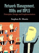
Like all great ideas, MIBs are fairly simple to understand. They provide a detailed description of the managed objects supported by a given device. As mentioned earlier, the MIB defines managed objects in a conceptual way, including the syntax and semantic information about each object. These managed objects can then be instantiated as real objects in an agent host device. Figure 2-5 is an extract from one of the draft MPLS MIBs [IETF-TE-MPLS] taken from the IETF Web site. As usual, we try to present the overall picture of a complete MIB. We will examine this MIB more closely in Chapter 8, “Case Study: MPLS Network Management.” It illustrates most of the general detail needed to understand MIBs. From Figure 2-5, we can see that MIBs are made up of just a few sections clearly identified by keywords. The main points of Figure 2-5 (identified by numbers and corresponding arrowheads) are the following:
The
BEGINkeyword indicates the start of the MIB (arrow 1).The
IMPORTSkeyword introduces descriptors from external MIBs in a similar way to#includein C andimportin Java. TheIMPORTSstatement identifies the descriptor and the module in which it is defined (arrow 2).The
MODULE-IDENTITYkeyword describes an entry point name for objects defined later in the MIB. The objects defined further down “hang” off this name (arrow 3), as shown by the black arrowed line.The
DESCRIPTIONkeyword provides details about the MIB content (arrow 4).The
REVISIONkeyword indicates the change history of the MIB (arrow 5).The
OBJECT IDENTIFIERkeyword defines either new managed objects or placeholders for them in the MIB (arrow 6).A sample, scalar, read-only integer object,
mplsTunnelConfigured, is shown (arrow 7).The remainder of the MIB (more scalars and tables) is skipped over (arrow 8).
The MIB finishes with the
ENDkeyword (arrow 9).
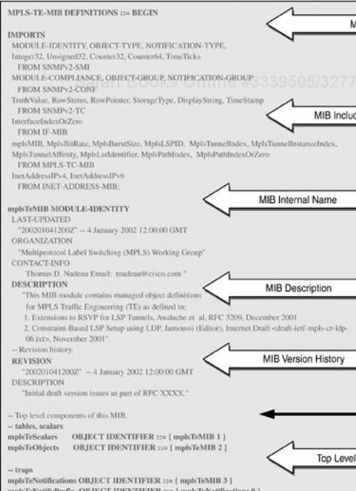
Figure 2-5 therefore includes most the elements of a MIB structure that will be encountered in practice.
MIB objects can be scalar (such as integers) or tabular (rows of other objects). In Chapter 8 we look closely at tables, particularly the MPLS MIB tables. The objects defined in the MIB are instantiated in the agent host and can be retrieved using a get operation via a MIB browser. Similarly (if they are read-write), they can be modified using a set operation. The SNMP agent asynchronously dispatches device notifications. Notifications are sent to a preconfigured IP address, usually that of the NMS.
Managed objects are the basic unit of exchange between an NMS and NEs. The managed objects are defined in the MIB and deployed in the network. The NMS provides software that, combined with the managed objects, gives the user the means of operating and maintaining the network. The importance of MIBs and managed objects cannot be overstated. The managed objects defined in the MIB must match the user's needs: not too detailed and also not too coarse-grained.
One merit of a standard MIB is ease of extension. As new technologies are invented and deployed, the associated managed objects must be defined in new MIB modules. The latter can then be added to the standard MIB in an orderly fashion, e.g., by using enterprise-specific numbers. New objects can be defined and included in MIB module files, such as the MPLS MIB files we will see in Chapter 8. The objects in such files are implemented in the NEs that support the associated technology (e.g., MPLS). The important point to note is that these are extensions to the standard MIB, i.e., there is only one MIB.
It may be helpful to draw some comparisons between a standard operating system (such as UNIX or Windows 2000) and an NMS. Both provide a set of abstractions to assist in the end use and management of the system. In the case of operating systems, some of the abstract objects are:
Files
Applications
Processes
Devices, such as hard disks and network interfaces
Soft objects, such as print jobs and semaphores
These abstract entities map onto real objects that users and applications employ for getting work done. NMS also employ the above objects in addition to other objects specific to network management. These NMS abstract objects are:
MIB modules
Applications—agents and managers
Devices—remote NEs
Soft objects—connections, paths, interfaces, and so on
These objects are used for managing networks. The NMS employs these objects and provides additional abstractions (GUI, software wizards, etc.) to assist the network operator.
The previous sections have introduced networks with a brief overview of some of their components and management infrastructure. This section examines NEs a little more closely. Figure 2-6 illustrates (in no particular order) some of the typical software components that combine to make up an NE.

An example of an NE is an intelligent line card, which is hosted inside another system, such as a PABX, ATM/MPLS switch, or IP router. An intelligent line card is essentially a computer inside another computer and may contain millions of lines of source code hosted on an embedded real-time operating system, such as pSOS or VxWorks. Some characteristics of intelligent line cards include the following:
They can extend the lifespan of the host by adding advanced functions such as SNMP and VoIP for a PABX.
They can take a long time to develop.
Operators like to extract the maximum performance from them—for example, port bandwidth.
They increasingly incorporate numerous layer 1, 2, and 3 protocols.
An NMS interacts with the SNMP agent in Figure 2-6, getting and setting MIB object instances and also receiving notifications. Clearly, the SNMP agent in the NE competes for compute and I/O resources with all the other onboard software entities. During times of high device loading, the SNMP agent may become starved of resources. This is a bad thing because the management facility can become essentially disabled. High loading can occur when:
Many voice calls are in transit through a PABX.
Large numbers of ATM virtual circuits are transporting many ATM cells.
Large numbers of IP packets are in transit across a router.
Network topology changes result in routing protocol convergence.
Compute resource depletion is one type of NE congestion. It can sometimes be cured by some combination of changing process priority, adding extra memory, or adding extra processing power. A more subtle problem is one in which the number of managed objects becomes so great that the NMS finds it hard to keep up with changes. This is the general area of scalability and is discussed in Chapter 3, “The Network Management Problem.”
We use MPLS as a running example throughout the book. Deployment of MPLS in the enterprise core is likely to occur only in extremely large organizations. Typically, such organizations have global reach and may already use a lot of ATM. Service providers are already deploying MPLS. Enterprises may initially deploy MPLS on WAN backbones and later on, they may move MPLS into the network core. In fact, the expansion of MPLS to the enterprise premises (via the MPLS UNI) is part of the work of the MPLS Forum.
On a more general note, a good understanding of MPLS is important for appreciating issues such as traffic engineering, network-QoS, and connection-oriented IP networks.
This section introduces the first chunk of MPLS [DavieRehkter2000] technology presented in this book. MPLS is essentially quite simple, but the building blocks are a little difficult to learn because they span both layers 2 and 3 and require some understanding of signaling and IP routing protocols. For this reason, the discussion is split into easy-to-understand, bite-sized chunks,[1] starting here and finishing up with the case study on some aspects of MPLS network management in chapters 8 and 9.
As mentioned earlier, a major trend in networking is the migration towards IP. Enterprise (and SP) networks are generally expected to support native IP cores in the next five to ten years. This is often referred to as the next-generation network. There are many reasons for this migration:
IP has become the lingua franca of networking—other protocols, such as Novell's IPX, will continue to exist, but the global protocol will almost certainly be IP version 4, possibly moving to IP version 6.
End-user devices, such as mobile phones, PDAs, and TV set-top boxes, have become IP-capable, so end-to-end IP (from the user to the core) will become more important.
Existing layer 2 devices do not easily support massive (scalable) deployment of layer 3 protocols such as is increasingly needed for services like IP VPNs.
The need for specialized layer 2 maintenance skills is reduced.
Aggregation of IP traffic becomes possible, improving scalability.
Different (guaranteed) levels of network service can be sold to customers.
Management system object models can become more generic.
Users will continue to access enterprise networks using a variety of technologies, such as ATM, FR, xDSL, ISDN, and POTS (dial-up), but their layer 2–encapsulated IP traffic will increasingly be extracted and repackaged as pure IP/MPLS at the network edge. In effect, layer 2 traffic is being pushed out of the core and into the access edge of the network. This is another reason for end-to-end IP: The need for terminating multiple layer 2 technologies begins to disappear. MPLS is a good starting point for this migration because:
MPLS allows traffic engineering (putting the traffic where the bandwidth is).
MPLS integrates IP QoS with layer 2 QoS.
Many vendors are providing MPLS capability in their devices—for example, Cisco, Juniper, Nortel Networks, and Marconi.
Many of the issues relating to traffic engineering, QoS, and handling legacy layer 2 services are highly relevant to enterprises and SP networks. Enterprise networks feature an increasingly rich mixture of traffic types: email, Web, audio/video, VoIP, and so on. Such a range of traffic types may well necessitate techniques such as traffic engineering and bandwidth management rather than just adding more capacity (i.e., overengineering the core).
MPLS is a forwarding technology. Its purpose is to receive an incoming traffic type (layer 2 or 3) at the network edge, encapsulate it, and then transmit it through an MPLS core (or cloud). At the exit from the cloud, another edge device removes the MPLS header and forwards the traffic towards its destination.
An example is illustrated in Figure 2-7, where the incoming IP traffic from the Acme enterprise network consists of a mixture of SMTP (email), HTTP (Web), and VoIP. This traffic is routed from IP Router 1 on the customer premises. The traffic then lands at the provider edge (LER1), where an IP header lookup is carried out on each packet prior to pushing an MPLS-encapsulated packet into the LSP (label switched path; this process is described in a little more detail below). The MPLS cloud in Figure 2-7 consists of many routers; a big network might have hundreds (or even thousands) of such routers distributed over a wide geographic area. The MPLS cloud routers in a real network would have many more edge connections than just the two IP routers shown. In other words, the SP network could have many thousands of such devices connected to it.

MPLS nodes are either edge or core devices. Edge routers are called label edge routers (LERs) and core routers are called label switching routers (LSRs). Edge routers (such as LER1 in Figure 2-7) sit at the boundary (or provider edge) of the network, facing the IP traffic stream on one side and the interior of the MPLS cloud on the other. Core routers, such as LSR1 in Figure 2-7, sit inside the MPLS cloud. Ingress LERs encapsulate IP traffic as MPLS packets and push these onto LSPs in the core of the MPLS cloud. We define LSPs more fully in the next section—for the moment, just think of them as layer 3 virtual connections or pipes that carry traffic from edge to edge through the network.
In Figure 2-7, IP Router 1 presents an IP traffic stream (SMTP, HTTP, VoIP) at an ingress interface of LER1. LER1 performs normal lookups on the IP headers of the incoming packets. From the destination IP address (or some other part of the IP header), LER1 can decide how best to forward the packets, and it has a number of choices. Taking the first IP packet that arrives, LER1 can:
In Figure 2-7, LER1 decides to take the last option in the above list, and the MPLS packet is transported via an LSP. The MPLS traffic is then pushed onto the LSP comprised of the ingress interfaces on the following nodes: LSR1-LSR2-LSR3-LSR4-LSR5-LSR6-LER2. This path is shown as a dashed line in Figure 2-7. An LSP has the following characteristics:
The path taken by the LSP may be either user-specified or computed by LER1.
The LSP may have reserved resources, such as bandwidth, along the path.
There is a link between LER1 and LSR3, but the incoming traffic does not take this route. Instead, traffic at LER1 is pushed onto the LSP and follows the route LER1-LSR1-LSR2-LSR3. This route overrides any default shortest path IP routing (between LER1 and LER2), giving the operator a greater degree of control in the paths taken by traffic (i.e., traffic engineering). In this sense, LSPs make the network connection-oriented, just like a telephone network.
IP traffic from IP Router 1 landing on LER1 is MPLS-encapsulated and forwarded across the LSP all the way to LER2. LER2 removes the MPLS encapsulation, carries out an IP lookup, and forwards the IP packet to IP Router 2. In other words, the traffic on the provider edge links is IP.
Only two IP lookups are required in getting from IP Router 1 through the MPLS cloud to IP Router 2. While line-rate IP lookups are now available in routers, MPLS provides this as well as the ability to create traffic-engineered connections (i.e., LSPs) that may or may not reserve bandwidth.
Once the IP traffic is MPLS-encapsulated, all subsequent routing is done using a label rather than any IP packet header-based addressing (the label structure is described in Figure 4-10 in Chapter 4).
As well as traffic engineering, MPLS provides a QoS function. This means that the LSP allocates network resources that enable it to ensure the traffic experiences a specified service level. We will see QoS in later chapters.
Some MPLS nodes can simultaneously function as ATM switches and MPLS nodes. ATM-based MPLS nodes have an important feature called ships-in-the-night (SIN). This allows both ATM and MPLS protocols to operate independently of one another on the same port (that is, MPLS is configured on the port, creating an MPLS interface). Not all MPLS nodes can simultaneously act as MPLS and ATM switches; for example, Juniper routers and Cisco 7000/12000 routers cannot. Some models of switches from Nortel, Lucent, and Marconi can. The provision of SIN is an effort to facilitate a gradual migration of networks from ATM to MPLS. Service providers can continue to deploy revenue producing, legacy services based on ATM while slowly introducing MPLS-based services (such as RFC 2547 VPNs). So, the nodes in Figure 2-7 can also create ATM virtual circuits alongside MPLS LSPs. These ATM circuits can then natively transport ATM cells. SIN conceptually splits a switch into a combination of an ATM and an MPLS device, like two mini-switches. It can result in a fragmented label space, and also there may be an effect on performance if a great deal of unlabeled IP traffic is in transit across the switch.
The MPLS nodes can run traffic engineering-enabled routing protocols such as Open Shortest Path First (OSPF) and Intermediate System-Intermediate System (IS-IS). This allows the exchange of traffic engineering data, such as available (and used) link bandwidth.
As we've seen, an LSP is an automatically or manually configured (optionally traffic-engineered with optional QoS) path through an MPLS network. An LSP originates on an LER, passes through zero or more LSRs, and terminates on another LER. The path taken by the LSP can be set by the operator or computed by the LER. Network resources, such as bandwidth, can be reserved along the path, or the LSP can offer a best-effort service.
With reference to the MIBs examined in Chapter 8, an LSP is comprised of the following components on the originating LER:
A tunnel
A cross-connect
An out-segment
Each LSR in the core then supports the LSP by providing the following components:
An in-segment
A cross-connect
An out-segment
Finally, the terminating LER provides the endpoint for the LSP using the following components:
An in-segment
A cross-connect
So, a notional network made up of two LERs and one LSR with an LSP spanning all three nodes might look like Figure 2-8.

Figure 2-8 illustrates the above components as well as another important concept: the IP/MPLS boundary. This boundary is the edge of the MPLS cloud; that is, on the IP side of the boundary there is only IP—all MPLS labels have been stripped off. On the MPLS side of the boundary there can be both IP and MPLS. In other words, there is no reason why pure IP traffic cannot traverse an MPLS core. Why might this arise? One possibility is that a packet arrives with a destination IP address that is not served by any existing LSP. In this case, the packet can be routed hop by hop through the MPLS core.
Packets arriving on the edge of the IP/MPLS boundary are subjected to a normal IP lookup, but if their destination address is served by an LSP, then they are MPLS-encapsulated and pushed into the appropriate tunnel (as illustrated in Figure 2-8). The encapsulated packets then pass through the segments and cross-connects of the LSP path, consuming any of the resources reserved on that path. One important part of LSP setup is the programming of the hardware. One of the major drivers of MPLS is that the MPLS management plane hides the platform-specific details. In this way, the platform-specific protocols impose the required labels, traffic engineering requirements, and QoS settings on the relevant interfaces across the network. The network operator employs the management interface to initiate this process. SNMP, in this context, is just another management interface, as is a CLI.
LSPs are set up from edge to edge traversing the LSRs in the core. LSPs serve as a conduit for transporting MPLS traffic from the point of ingress at the edge to the point of egress on another edge. We will see the structure illustrated in Chapter 8. One final important point about MPLS is that it is not restricted to carrying just IP traffic. The traffic landing at LER1 can also be Ethernet, ATM, and TDM. Carrying legacy traffic is an important part of MPLS.
SNMPv3 provides several compelling advantages over previous versions. Authentication and strong security; improved error, exception, and notification reporting; and bulk operations are among the most important. SNMPv3 features like these can help make life a lot easier for network managers. Setting up security on a networkwide basis is still a difficult task. The different versions of SNMP require support in a given NMS. This consists of community strings and trap/notification destination settings. The latter is also required in SNMPv3. For SNMPv3, community strings are not used. Instead, the user must set up the required level of authentication and encryption.
MIB browsers represent an indispensable tool for both NMS software developers and network managers. They provide a detailed view of MIB objects. While MIBs can be defined with arbitrary complexity and size, they all have a relatively simple structure. Understanding this structure is a key element of studying network management technology. An essential point to note about managed objects is that there is just a single MIB. The MIB can be extended to support new objects, such as, those for MPLS.
An NMS can also be arbitrarily complex with a great many components. However, a typical NMS is at least conceptually similar to other more familiar applications, such as operating systems. Just as for MIBs, it is important to gain a good conceptual understanding of the NMS structure.
NEs are those components that combine together to make up a managed network. There are some broad similarities between many NEs, and an appreciation of these helps in deciding how to manage them.
MPLS is an extremely important technology that is being widely deployed in SP networks and also in some enterprise WANs. The major components of this technology were described in order to lay the foundations for Chapter 8, where we examine the mechanisms for creating MPLS-managed objects.
[1] This is in keeping with our concepts of learning about network management and creating NMS solutions. These ideas are introduced in later chapters, but for now we say that a given technology must be understood before an attempt is made to manage it. This is obvious enough, but the depth of understanding is the key. In many cases, a good overview is all that is needed to get started on producing an NMS solution. This is the model we use with MPLS.