C
C and C++ See computer language.
cabled distribution system Same as wire broadcasting.
cache An area of high-speed memory used to speed up computer processing. Caches are used in disk read and write operations, in storing character bitmaps and, above all, in central processing unit operations.
calibrate To adjust test equipment against a standard to ensure that it is working accurately.
camcorder A television camera and video cassette recorder combined in one portable unit. Camcorders are widely used by broadcasting professionals for newsgathering and location work and by hobbyists for creating ‘home movies’. It replaces the cine camera formerly used for these purposes and has the advantages over them that no film processing is required so that instant playback is available and that the medium is reusable.
camera tube An electron tube used in a TV system to produce picture signals by scanning a charge image derived from an optical image of the scene to be televised. The various types of tube that are used in black-and-white or colour TV can be classified according to the type of target used (i.e. whether photo-emissive or photo-conductive) and according to the velocity of the scanning beam (i.e. whether high or low).
The earliest tubes such as the iconoscope and image iconoscope had photo-emissive targets and high-velocity scanning beams. The optical image and the scanning beam were projected on the same face of the target and the beam was arranged to scan the target obliquely so that the electron gun did not impede the light path. The chief disadvantages of these tubes (low sensitivity and the presence of strong shading signals in the tube output) stemmed from secondary electrons released from the target as a result of bombardment by the high-velocity scanning beam.
To avoid these difficulties the beam velocity was reduced to a value at which no secondary emission occurred and in this way the orthicon and image-orthicon tubes were developed. The low-velocity scanning beam lands on the target and drives its potential negative until it reaches electron-gun cathode potential. When the target potential has been thus stabilised, the scanning beam is slowed to zero velocity as it approaches the target. One of the chief problems with low-velocity tubes is that of focusing and deflecting such a beam. This was solved by use of orthogonal scanning and a long magnetic lens: these ensured that the beam always approached the target at normal incidence so that the optical image could not be focused on the scanned face. A combined transparent signal plate and target electrode was developed which enabled the optical image to be projected on one face whilst the rear face was scanned by the beam. Orthicon tubes were first used in TV in 1946. They were free of shading signals but lacked sensitivity and the target stabilisation could be lost on receipt of a large light input.
Both disadvantages were overcome in the image-orthicon tube which included an image section, a stabilising mesh to prevent loss of target stabilisation and an electron multiplier into which the return scanning beam was directed. This is a highly-sensitive tube and was extensively used in black-and-white TV services for many years. It is, however, too bulky for use in colour cameras where three or four tubes are necessary. Instead, therefore, attention was directed towards photoconductive tubes (vidicons) which could be made very simple and compact.
In vidicon tubes, the target consists of a transparent signal plate on which is deposited a layer of photo-conductive material. The scanned face of the target is stabilised at electron-gun cathode potential as in any low-velocity tube and the signal plate is given a small positive bias. Current thus flows longitudinally through the target thickness and the magnitude of this current at any point on the target depends on the target resistance which in turn depends on the illumination of the target at that point. Early vidicon tubes suffered from lag, i.e. there was an appreciable delay between a change of light input and the corresponding change in target resistance but intensive work on photoconductive materials has resulted in satisfactory sensitivity and lag. Most modern colour television cameras incorporate three or four vidicon tubes.
cannibalise To strip serviceable components from one or more (usually nonfunctioning) equipments in order to build one that works.
capacitance (C) A property of two conductors, electrically insulated from each other, which enables them to store charge when a potential difference exists between them. The capacitance is defined as the quotient of the charge and the potential difference thus
The unit of capacitance is the Farad (F), this being the capacitance when the charge stored is one coulomb and the potential difference is one volt. For many purposes this unit is too large and the submultiples the microfarad (μF) equal to 10−6 F and the picofarad (pF) equal to 10−12 F are used instead.
capacitance diode Same as varactor.
capacitance potentiometer A number of capacitors connected in series across a source of alternating voltage, the interconnections acting as tapping points from which a desired value of voltage can be taken. In the simplest example there are only two capacitors as shown in Figure C.1 and the step-down ratio is given by
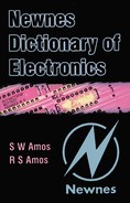
capacitive coupling Coupling between two circuits by virtue of mutual capacitance. The coupling capacitor may be a component connected in series with the circuits as in Figure C.2 (a) or it may be a shunt component as in Figure C.2 (b). In Figure C.2 (a) the coupling coefficient is given approximately by C/C1 where C is assumed small compared with C1 and C2. In Figure C.2 (b) the coupling coefficient is given approximately by C1/C, where C is assumed large compared with C1 and C2. In both circuits C1 is assumed equal to C2.

capacitor A component consisting essentially of two plates or electrodes separated by a dielectric and used because of its capacitance. The capacitance is proportional to the area of the plates and to the dielectric constant of the insulator and is inversely proportional to the thickness of the dielectric. There are many different types of capacitor varying in capacitance between a few pF and thousands of μF and varying in voltage rating from a few volts to several kilovolts. The plates are often of aluminium and the most commonly-used dielectrics are impregnated paper, mica, plastics, ceramics, air and vacuum. The graphical symbol for a capacitor is given in Figure C.3 and the component reference is C. See electrolytic capacitor.
capacitor loudspeaker Same as electrostatic loudspeaker.
capacitor microphone Same as electrostatic microphone.
capacitor store A store in which each bit of data is held as a charge on a capacitor. Dynamic RAMs are of this type.
capture ratio The ability of a radio receiver to select the stronger of two signals at the same frequency. It is measured in decibels, the figure representing the ratio of the closest signal strengths that can be resolved.
carcinotron Same as backward-wave oscillator.
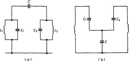
cardioid response Type of response represented by a heart-shaped polar diagram. Such a diagram is obtained by combining a circular diagram with a figure-of-eight diagram as shown in Figure C.4. A cardioid polar diagram is useful in radio direction finding and is obtained by combining the omnidirectional response of a vertical antenna with the figure-of-eight reponse of a loop antenna.
A cardioid response is also useful in a microphone because it gives a 180° live area, i.e. it makes the microphone effectively single-sided—ideal for positioning in stage footlights with the dead side towards the audience. This type of response can be obtained from a microphone which combines the omnidirectional (pressure) mode of operation with the figure-of-eight (pressure-gradient) mode of operation. See pressure-gradient microphone, pressure microphone.
card reader In early data processing equipment a device which reads the data on a punched card. Reading was by electromagnetic feelers or photoelectric scanning.
caret An I-shaped cursor used especially in computer displays that have proportionally spaced characters. The caret is positioned between characters, unlike a conventional rectangular cursor which is positioned directly over fixed-pitch characters.
carrier storage An effect in pn junctions which have been driven hard into conduction whereby the current continues to flow for a brief period after the applied voltage has been removed. More majority carriers move towards the junction than are needed to supply the external current: these are stored and are able to continue the current briefly when the applied voltage is reduced to zero.
carrier suppression A system of AM radio transmission in which the carrier wave is not transmitted or is transmitted at very low level. This is permissible because the information to be transmitted is carried in the sidebands. At the receiving end the carrier must be re-introduced to make detection possible and a suitable signal is generated locally for this purpose.
carrier wave A continuous wave, usually sinusoidal, of constant amplitude and frequency and intended for angle or amplitude modulation. The term is also used to describe the carrier-frequency component of a modulated wave. See amplitude modulation, angle modulation.
carry In computers and data-processing equipment the digit added to the next highest digit position when the sum of the digits in the lower position exceeds the base number.
cascade A circuit arrangement in which the output of one stage of amplification or section of a filter, etc, forms the input of the next stage.
cascode An amplifier consisting of a common-emitter stage feeding into a common-base stage. The arrangement avoids instability by feedback via the collector-base capacitance in the common-emitter stage and can thus be used for stable VHF and UHF amplification. The two transistors are often connected in series across the supply as shown in Figure C.5. The circuit arrangement can be used with electron tubes and with field-effect transistors: in fact a tetrode FET is equivalent to two triode FETs in series.

cassette A container holding sensitive storage media such as tape or film. The container protects the media against light, grease and dust and also makes it easier to handle. Audio compact cassettes and video cassettes in various formats are probably the best known examples.
catalogue A display of the contents of a directory.
catcher The electrodes and associated cavity resonator in a velocity-modulated tube which extracts energy from the bunched beam. See velocity modulation.
catcher diode A diode used to prevent the voltage at a particular point in a circuit from rising above or falling below a predetermined value.
cathode In general the electrode in any electron tube which is connected to the negative terminal of the supply. In electron tubes the source of electrons for the principal electron stream. In a glow-discharge tube the cathode may be cold and electrons are then liberated by bombardment of the cathode by heavy positive ions. In photocells electrons are liberated from the cathode under the stimulus of incident light. In most electron tubes, however, the cathode is heated to liberate electrons and it may take the form of a filament directly heated by the passage of an electric current through it or the cathode may be indirectly heated. See cold cathode, glow discharge, indirectly-heated cathode.
cathode AC resistance See electrode AC resistance.
cathode bias Same as automatic cathode bias.
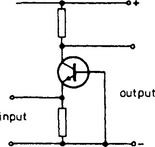
cathode follower An electron tube in which the load is connected in the cathode circuit, see Figure C.6. This gives 100% negative feedback which reduces the voltage gain to just less than unity. Signals applied to the grid thus emerge with little loss from the cathode; in fact, the cathode voltage ‘follows’ that of the grid. The advantage of the circuit lies in its high input resistance and low output resistance which make it suitable as a buffer stage. There are corresponding emitter follower and source follower circuits.

cathode ray oscillograph An instrument for producing permanent records of the waveform of varying electrical quantities. The records are generally obtained by photographing the screen of a cathode ray oscilloscope and the provision for attaching a camera to the cathode ray tube is the only distinction between an oscillograph and an oscilloscope.
cathode ray oscilloscope (CRO) Instrument containing a cathode ray tube used for examining variable electrical quantities, periodic or transient, by displaying the waveform on the screen. For examining periodic waveforms the electron beam is deflected horizontally (i.e. in the X direction) by a sawtooth generator acting as a time base. The signal to be examined is applied to the vertical deflection system (Y direction) usually after amplification. By adjusting the time-base frequency to an exact submultiple of the fundamental frequency of the waveform a stationary pattern can be produced on the screen and detailed observation of the shape of the waveform is possible. To help in obtaining a stationary pattern there is provision for synchronising the time-base generator to the waveform.
The oscilloscope is one of the most widely used tools in electronics. In addition to its obvious application in examining waveforms to detect harmonics or the presence of spurious signals it can be used in conjunction with a wobbulator for the alignment of receivers. Oscilloscopes are also widely used as indicators in radars. They are also extensively employed in the examination of any physical quantity (e.g. mechanical stress) which can be converted into a corresponding electrical signal. See double-beam oscilloscope, oscillograph.
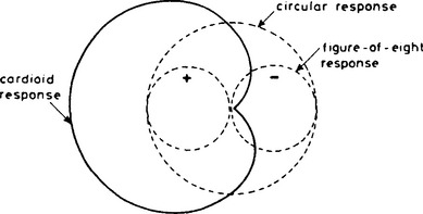
cathode ray tube (CRT) An electron tube in which an electron beam is focused on a phosphor screen and is deflected to give a visible display. Such tubes are extensively used in oscilloscopes, in radars, and as picture tubes in TV receivers. Essentially the tubes comprise an electron gun for generating the beam, a system (either electrostatic or magnetic) for focusing the beam on the screen, a system (also either electrostatic or magnetic) for deflecting the beam, and finally a screen coated with a phosphor which emits light when struck by the beam. Figure C.7 illustrates the construction of a cathode ray tube with electrostatic focusing and electrostatic deflection, the type commonly used in oscilloscopes.
Figure C.7 Construction of cathode ray tube with electrostatic focusing and deflection: K, thermionic cathode; G, control grid; A1, focusing anode; A2, accelerating or final anode; V1, V2, plates for vertical deflection of the beam; H1, H2, plates for horizontal deflection of the beam; S, luminescent screen
cathode ray tuning indicator (also known as electron ray tube (US)). A small electron tube incorporating a triode amplifier and a simple cathode ray tube in which the area of luminescence on the screen can be controlled by the signal applied to the triode control grid. It was chiefly used as a tuning indicator in radio receivers the area of the display being controlled from the AGC line. The graphical symbol for the device is given in Figure C.8.

cation Positively-charged ion formed in a gas by ionisation or in an electrolyte by dissociation and which moves towards the negatively-charged electrode (cathode) under the influence of the potential gradient. See anion.
cat’s whisker A pointed length of wire, usually copper, which was lightly pressed against a sensitive part of a crystal, e.g. galena, to form a rudimentary form of point-contact diode. This was used for AM detection in the early days of broadcasting in the 1920s.
cavity magnetron A magnetron in which the anode contains a number of cavity resonators facing inwards towards the cathode. The electron stream can be made to circulate around the cathode within the space between cathode and anode, and can thus become velocity modulated as a result of passing close to the mouths of the resonators. The resultant bunching of the beam can, by suitable choice of electric and magnetic field strengths give rise to oscillation at the resonance frequency of the cavities. The resultant energy can be directed into a waveguide by means of a coupling loop in one of the resonators. In this way microwave oscillations of considerable power can be generated. See cavity resonator, velocity modulation.
cavity resonator A cavity contained by a conducting surface the size and shape being chosen to give resonance at a particular frequency of electromagnetic waves. At microwave frequencies such resonators replace the lumped inductance and capacitance used in tuned circuits at lower frequencies.
C battery (US) A battery used to supply the grid bias voltage for electron tubes.
C core A magnetic core for a choke or transformer consisting of two C-shaped sections butted together to form a closed magnetic circuit. The C sections are made by winding magnetic alloy tape into a spiral and then cutting the resultant ring into two. C cores have better magnetic properties than laminated cores because the magnetic grain is parallel to the length of the tape. C cores are also easier to assemble with choke or transformer windings.
Ceefax The teletext service of the BBC.
cell (1) A device containing two electrodes and capable of generating an EMF between them. The electrodes may be immersed in a electrolyte and generate the EMF as a result of chemical action (see voltaic cell). Alternatively one of the electrodes may be light-sensitive and produce the EMF as a result of illumination by light (see photocell). (2) An elementary unit of a store, e.g. a memory cell (see store). (3) The area served by a base station in a cellular radio system.
cellular radio A radio-based mobile communications system in which numerous low-power base stations each cover a small area or cell, all under the control of a central computer. As a mobile user leaves the area served by one base station, the computer determines which of the surrounding base stations now offers the best transmission path and switches the user over to that base station in a transparent process.
central processing unit (CPU) or central processor In a digital computer or data-processing equipment the unit containing the arithmetic, logic and control circuits which direct and co-ordinate operation of the computer and the peripheral devices.
centre frequency In frequency modulation, the carrier frequency.
Centronics printer standard The most widely used method of transferring data from a computer to a printer. The system uses 36-pin plugs and connectors with eight parallel conductors carrying data, making it faster than alternative serial transmission systems.
ceramic A class of material of very high resistivity and sometimes of high permittivity or permeability or with piezo-electric properties. Thus ceramic materials are extensively used in electronics in magnetic cores (as ferrite), as dielectrics and as piezo-electric elements. Ceramics cannot usually be machined and are cast into shapes suitable for their application.
chain code A binary code in which each word is derived from the previous word by shifting the bits one place to the left or the right, dropping the leading bit and inserting a bit at the end. This cyclic sequence ensures that a word cannot recur until the cycle is repeated.
channel (1) In telecommunications generally, a unidirectional signal path. (2) In particular a limited band of frequencies allocated to the transmission of a signal. The channel must be wide enough to accommodate all the significant components of the signal, e.g. side frequencies of a modulated signal. When channels are closely packed in a waveband, the spacing is made greater than the channel width to give a guard band between adjacent channels. Television channels are identified by numbers in the UK, e.g. channels 21 to 68 are in Bands IV and V. (3) Of a field-effect transistor the semiconductor layer along which majority carriers flow from the source to the drain terminals. The effective width of the channel and hence its electrical resistance is controlled by the voltage applied to the gate.
channel multiplier A type of electron multiplier of tubular construction in which the secondary-electron-emitting material is in the form of a continuous internal surface.
characteristic curve In general a curve representing the relationship between two quantities which illustrates the behaviour of a device or equipment. The term is, however, usually reserved for the curves which show how the current at an electron-tube electrode depends on its voltage or the voltage at another electrode, e.g. the Ia–Va or the Ia–Vg curves of an electron tube.
characteristic impedance The value approached by the input impedance of an open-circuited transmission line as its length is increased. This is also the value of impedance which, if used to terminate the line, gives an input impedance of the same value. Two types of transmission line commonly used for RF transmission are the twin-wire and coaxial cable. At RF the reactance of the distributed inductance and capacitance of the conductors has more effect than the resistance and the characteristic impedance is given by
where L and C are the inductance and capacitance per unit length of line. For twin-wire and coaxial cables the characteristic impedance can be calculated from the dimensions of the cross-section as indicated in Figure C.9.
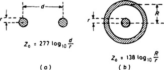
A significant point about the characteristic impedance is that if a finite length of line is terminated by an impedance equal to the characteristic impedance then the line behaves as if it were of infinite length and no standing waves are set up on it. RF energy can thus be transmitted along it without reflection.
character recognition See optical character recognition.
charge carrier A charged particle which, in moving under the stimulus of an electric field in a conductor, constitutes an electric current. Examples of charge carriers are the positively- or negatively-charged ions in an electrolyte and the electrons and holes in a semiconductor.
charge-coupled device (CCD) A device in which charges on a semiconductor surface and under gate electrodes can be transferred as a packet to an adjacent area of the surface by voltage pulses applied to the gates. Such a device can be used for data storage. If the gate electrodes are thin, parallel and equidistant conducting strips then, by applying suitably-phased clock pulses to the strips, any charges placed on the semiconductor surface under the first gate are transferred along the surface of the device as in a shift register.
The method of manufacture of such devices has much in common with that of IGFETs but is simpler in that no contacts or diffusions are required. The devices can be manufactured with very small dimensions so that great packing density is possible. They can thus be used as serial stores and can compete with magnetic disks and tape: indeed they are smaller than disk or tape for a given storage capacity but CCD stores are, of course, volatile. See volatile store.
charge image In TV the pattern of electric charges on the target surface of a camera tube which results from the optical-image input and which, when scanned, gives rise to the picture-signal output from the tube.
charge-storage tube An electron tube in which information is retained on its active surface in the form of a charge image. In most television camera tubes the image is stored on the target electrode in this form and is ‘read off by the scanning beam. Storage tubes used in VDUs also use similar principles.
charge transfer device (CTD) A semiconductor device which enables discrete packets of charge to be moved from one position to another. There are two main types: bucket-brigade devices and charge-coupled devices.
Chebyshev response A response curve in which the deviations from the ideal curve are made as small as possible and approximately equal to each other over the frequency band of interest. The parameters of filters are often chosen to give a Chebyshev response.
chip Popular name for an integrated circuit.
chip carrier A plastic or ceramic container for a monolithic integrated circuit, the connections to which are brought out to contacts on all four sides of the package and are designed for surface mounting on a printed wiring board. The chip carrier is an alternative to the DIP for a large number of contact pins and gives considerable saving in space because of its smaller contact spacing. It also gives a better thermal performance and higher speed of operation because the contacts are shorter than the pins of a DIP.
Chireix system An amplifying system used in AM transmitters in which two constant-voltage phase-modulated signals drive two saturated amplifiers feeding a common load. The power output is a function of the phase difference between the two signals and this is controlled by the modulating signal. The system was developed in France by H Chireix in the 1930s. See ampliphase system.
choke An inductor, the reactance of which over a particular band of frequencies is large compared with a given impedance. For example an RF choke may be used at the input of an audio-frequency amplifier to prevent RF signals entering the amplifier. In such an application the choke is likely to be followed by a shunt capacitance and for successful results the reactance of the choke must be large compared with that of the capacitance so as to give great attenuation at RF.
chopping Periodic interruption of an electrical signal or a beam of light. This can be achieved by electrical or mechanical means and is used to transform a direct-current signal into an alternating signal. DC amplification is often achieved in this manner, the chopped signal being amplified in conventional capacitance-coupled amplifiers and then reconverted into DC form.
chromatic aberration Defect in an optical lens due to variation of the refractive index of the material with the wavelength and causing coloured fringes in images. The defect is usually eliminated by constructing lenses of two different materials, e.g. crown and flint glass, which give refraction without dispersion. Such combinations are known as achromatic pairs.
chrominance Those attributes of a colour which can be defined by stating the hue and saturation.
chrominance amplifier The circuits which amplify the chrominance signal.
chrominance signal In colour television the signal which is added to the luminance signal to give colour information. In the NTSC and the PAL systems the chrominance signal is generated by so modulating the chrominance subcarrier that its instantaneous phase relative to that of the colour burst represents hue and its amplitude represents saturation.
circle diagram A set of graphs for the solution of transmission-line problems. Normalised resistance (R/Zo) and normalised reactance (X/Zo) are plotted on Cartesian or polar co-ordinates and the diagram can be used to calculate, for example, the impedance of a given length of line when terminated in any value of impedance. Zo is the characteristic impedance of the transmission line.
circuit (1) A path consisting of a conductor or a system of conductors through which an electric current can flow. (2) A network which may contain active and passive devices and may have one or more closed paths and which is intended to carry out a particular function. For example an amplifier may be said to have a circuit. (3) In telecommunications a means of bidirectional communication between two points.
circular polarisation Elliptical polarisation in which the amplitude of an electromagnetic wave remains constant whilst the plane of polarisation rotates. Vertically- or horizontally-polarised radio waves can become circularly-polarised after refraction in the ionosphere. Circular polarisation is used at some FM broadcasting stations to ensure that the signal can be received equally well on vertical and horizontal antennas.
circulating register (1) A register which retains data by inserting it into a delay device, by regenerating the data and re-inserting it into the register. (2) A shift register in which data removed from one end is put into the other end in a cyclic sequence.
clamp A circuit for ensuring constancy of the potential of a particular section of a recurrent waveform. Clamps are used in television transmission to ensure that the parts of the waveform which represent black in displayed pictures are maintained at a constant potential. To enable a clamp to operate at the desired instants it is driven by clamping pulses which are synchronised with the waveform to be clamped.
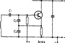
Clapp oscillator A Colpitts oscillator in which frequency stability is improved by using separate capacitors for tuning and for providing capacitive feedback. A circuit is shown in Figure C.10 where C1 is the tuning capacitor and C2 and C3 are high-value capacitors which provide the connections to the active device and swamp any variations in the input capacitance of the device.
class-A operation Operation of an active device in which the bias and signal amplitude are so chosen that output current flows throughout each cycle of input signal (assumed sinusoidal), i.e. the angle of flow is 360°.
This mode of operation is used in most small-signal stages of analogue equipment such as amplifiers and receivers, a linear part of the input-output characteristic being chosen to minimise waveform distortion as shown in Figure C.11. It is an inefficient mode of operation because the mean current of the active device is independent of the amplitude of the input signal. By utilising the maximum current and voltage swings possible the theoretical efficiency of a class-A output stage (measured by the ratio of the output power to the power taken from the supply) is 50% for a constant-amplitude signal. In AF amplification where signal amplitudes are constantly varying the practical efficiency is unlikely to exceed half this figure.
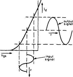
Figure C.11 Id–Vgs characteristics of a junction-gate FET with input and output signals for class-A operation
class-AB operation Operation of an active device which is biased to give class-A operation for small-amplitude input signals and class-B operation for large-amplitude signals, i.e. the angle of flow is between 180° and 360°. For electron tube amplifiers the suffix I is added after the letters AB to indicate that grid current does not flow at any period during the input-signal cycle and the suffix 2 is added if grid current is allowed to flow.
class-B operation Operation of an active device which is biased almost to output-current cut-off so that current flows only during one half of each cycle of sinusoidal input signal, i.e. the angle of flow is 180° This mode of operation, illustrated in Figure C.12 is very efficient because the mean current of the active device is directly proportional to the signal amplitude and is almost zero for zero input signal. The output signal is, of course, a reproduction of only one half of each cycle of input signal but linear amplification is possible by using two class-B stages in push-pull operation and most of the output stages in transistor amplifiers and receivers are of this type.
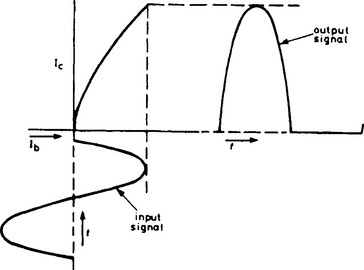
Figure C.12 Ic–Ib characteristic of a bipolar transistor with input and output signals for class-B operation
The theoretical efficiency of a class-B stage (measured by the ratio of the output power to the power taken from the supply) is 78% and efficiencies approaching this value can be obtained in practice. The chief source of inefficiency is the no-signal or quiescent current which must be great enough to minimise crossover distortion. For electron tube amplifiers the suffix 1 is added after the letter B to indicate that grid current does not flow at any time during the cycle and the suffix 2 is added if grid current is allowed to flow.
class-C operation Operation of an active device which is biased beyond cut-off of output current so that current flows for less than one half-cycle of sinusoidal input signal, i.e. the angle of flow is less than 180°. This mode of operation, illustrated in Figure C.13, cannot be used for linear amplification but is extensively used for RF amplification, e.g. in transmitters where a tuned output-load circuit rejects harmonics and gives a sinsoidal output signal. Efficiency (measured by the ratio of the output power to the power taken from the supply), can be very high indeed—approaching 90%. For electron-tube amplifiers the suffix 1 is added after the letter C to indicate that grid current does not flow at any period during the input-signal cycle and the suffix 2 is added if grid current is allowed to flow.
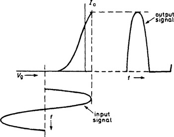
Figure C.13 Ia–Vg characteristic of an electron tube with input and output signals for class-C operation
class-D operation Operation of an active device with a pulse-width-modulated input signal. Very high efficiency (measured by the ratio of output power to the power taken from the supply) is possible from a class-D stage because the input is of constant amplitude so permitting maximum use to be made of the current and voltage swings available in the output circuit. See pulse-width modulation.
clear input In computers and data-processing equipment a signal applied to a store to put it into a prescribed state, usually the state of zero stored information.
click A transient signal of very short duration. The term describes the sound of the signal when reproduced by an acoustic transducer.
client In a computer network, a user or the user’s computer or terminal or the code used at the user’s end of the network.
client server In a computer network, a computer from which users (clients) can request stored data and applications.
clip art Computer graphics, usually copyright-free, supplied for the express purpose of illustrating documents produced using computer systems.
clipboard In computing, an area of memory reserved for the exchange of data between applications or between documents in a single application or within one document.
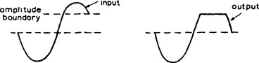
clipping The process of suppressing that part of a signal waveform which lies to one side of an amplitude boundary. In the example illustrated in Figure C.14 the parts of the waveform which are more positive than the boundary are suppressed.
clock In computers and data-processing equipment the generator of periodic signals, known as clock pulses, which govern the timing of the logic and other operations carried out by the equipment.
clock speed The frequency of the quartz crystal that regulates the operation of a central processing unit. Although this is a widely quoted criterion when comparing the performance of computers, it is not the only factor affecting the speed at which computers execute tasks. In some applications memory access time or hard disk access time may be the limiting factor.
closed circuit A circuit which is not broken and therefore in which a current can flow. In broadcasting the term is used to describe a circuit used for rehearsal or recording of a programme which is not radiated at that time to listeners or viewers.
closed-loop control A servo system in which the controlled quantity is measured and compared with the desired value and any difference is fed back into the control system so as to minimise the difference.
clustered dither See dithering.
CMYK colour model See colour model.
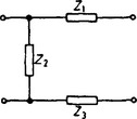
C-network A network containing a single shunt element and two series elements, one in each leg as shown in Figure C.15. It can be regarded as a balanced form of the L-network.
coaxial cable; coaxial line; concentric line A transmission line formed from two conductors, one a wire and the other a cylinder concentric with the wire, the space between them being filled with a dielectric. Cables of this type are extensively used for carrying RF signals at frequencies above approximately 10 MHz. Because the fields are confined within the outer conductor there is negligible loss by radiation from a coaxial cable. See characteristic impedance.
coding In general a method of representing information by means of characters suitable for the intended equipment or transmission system. For example in the Morse Code information can be expressed in normal language which can be spelled out, each letter of the alphabet being represented by a unique combination of dots and dashes. Thus A is – and B is –![]() . Such a code is suitable for signalling by flashing a light, sounding a buzzer or interrupting an RF carrier. For digital computers a binary coding system is generally used.
. Such a code is suitable for signalling by flashing a light, sounding a buzzer or interrupting an RF carrier. For digital computers a binary coding system is generally used.
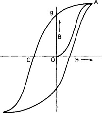
coercive field strength or coercive force The minimum reverse magnetic field strength which must be applied to a material to reduce the magnetic flux density to zero. It is represented by OC in Figure C.16 and its value depends on the value of the magnetic flux density initially induced in the material.
coercivity The coercive field strength for a material which has been magnetically saturated.
coherence The maintenance of a fixed frequency. For example a laser is regarded as a coherent oscillator. In interrupted oscillations, coherence implies the maintenance of phase continuity so that, at the beginning of each packet of oscillations the phase has precisely the value it would have had if the interruption had not taken place.
coincidence circuit or coincidence gate A gate which produces an output pulse when, and only when, all the inputs receive pulses simultaneously or within a prescribed time interval. See logic gate.
cold cathode A cathode which emits electrons without being heated. This definition strictly embraces photo-emissive cathodes but the term is usually reserved for the type of cathode used in some gas-filled tubes. Electron emission from the cathode arises as a result of bombardment by heavy positive ions released by ionisation of the gas and can be improved by coating the cathode with materials of low work function.
collector (1) In a bipolar transistor, that region into which charge carriers are swept from the base region. The carriers are minority carriers in the base region but majority carriers in the collector region. The collector-base junction is reverse-biased in normal transistor operation and hence the majority carriers are swept away from the junction and towards the collector terminal. (2) The term is also used to imply a collector of electrons, i.e. the anode in certain types of electron tube.
collector AC resistance See electrode AC resistance.
collimator A device for deflecting the paths of electrons or light rays in a non-parallel beam so as to produce a parallel beam.
colour See hue and saturation.
colour burst In colour television a synchronising signal consisting of a few cycles of chrominance subcarrier transmitted within the back porch of each line period and used to lock the frequency and phase of the reference oscillator in receivers.
colour cell Of a colour picture tube the smallest area of the screen which includes a complete set of primary colours. For example in a delta-array tube the triangle which includes one red, one green and one blue phosphor dot.
colour code A system of colours for indicating the values, tolerances and ratings of components or the connections to them. The most familiar colour code is that used on resistors. As shown in Figure C.17 four bands of colour are used. The first (nearest the end of the resistor) indicates the first figure of the resistance value, the next band gives the second figure and the third indicates the multiplier, i.e. the number of noughts which follow the second figure. The fourth band indicates the tolerance. The code used is as shown in Tables C.1 and C.2. As an example a resistor in which the bands are coloured yellow, violet, orange and silver is of 47 k Ω resistance, tolerance ±10%. In an older system (also indicated in Figure C.17) the first figure of the resistance value was indicated by the body colour, the second figure by the end colour and the multiplier by a dot colour. A similar code is used for capacitors to indicate the capacitance in pF.
Table C.1
| Resistance | |
| 0 black | 5 green |
| 1 brown | 6 blue |
| 2 red | 7 purple |
| 3 orange | 8 grey |
| 4 yellow | 9 white |
Table C.2
Tolerance
±1% brown
± 2% red
± 5% gold
± 10% silver
± 20% no fourth band

colour-difference signal In compatible colour television systems the signal obtained by subtracting the luminance signal from one of the three primary colour signals. Two colour-difference signals are used to modulate the colour subcarrier, quadrature modulation being used in the NTSC and PAL systems and frequency modulation in the SECAM system. At the receiver, after detection, the colour difference signals are added to the luminance signal to yield the red, green and blue colour signals required as inputs to the picture tube.
colour model A means of defining a colour mathematically. Colour models are used in television and in computer graphics and desktop publishing. The three colour models most regularly used are as follows.
The RGB (red/green/blue) model regards all colours as made up from the sum of the values of the three primary colours detected in human eyesight and used in the phosphor dots in a colour cathode ray tube. The values of the individual primaries are sometimes expressed as percentages and sometimes as numbers between 0 and 255 (see true colour). Thus white is 255,255,255 (all primaries turned fully on) and magenta is 255,0,255 (full red and full blue but no green).
The HSV (hue/saturation/value) model is based on the way in which the human brain interprets colour information. Hue represents the wavelength or perceived colour (such as green or violet). Saturation represents the concentration of the colour; if saturation is low the colour is pale, i.e. mixed with white. Value represents the overall level of the colour. All three figures are most commonly expressed as percentages, although hue is sometimes expressed as an angle (between 0 and 359°). Note that if value is 0, the colour is black irrespective of the hue or saturation figures and if value is 100 and saturation is 0, the colour is white irrespective of the hue.
The CMYK (cyan/magenta/yellow/key) model is based on the behaviour of the inks used in colour printing. Cyan, magenta and yellow allow a wide range of colours to be simulated by overprinting. The inks are assumed to be printed on a white background and the colours are subtracted. Thus cyan and yellow make green while magenta and yellow make the crimson sometimes called ‘warm red’. Key is black and is used both to print truly black areas and to produce darker shades of other colours. Values are expressed either as pecentages or as numbers between 0 and 255.
colour television Television in which the pictures are reproduced in colours simulating those of the original scene. At the transmitting end an image of the original scene is analysed into its red, green and blue components and information about these components is contained in the chrominance signal. Modem colour TV systems are compatible and the transmitted signal is basically that of a black-and-white system to which the chrominance signal is added to give information about the hue and saturation of the colours in the scene. The chrominance information is conveyed by a colour subcarrier which, with its sidebands, is interleaved with the sidebands of the black-and-white (luminance) signal. A number of different subcarrier modulation systems are in current use. See compatibility, chrominance, NTSC, PAL, SECAM.
colour temperature Of a light source the absolute temperature of a full radiator (black body) which gives the same colour.
colour video signal or composite colour signal (US) In colour television the signal which gives complete colour-picture information and includes synchronising signals and colour burst.
Colpitts oscillator A sinusoidal oscillator in which the frequency-determining element is a parallel LC circuit connected between input and output terminals of an active device, positive feedback being obtained by connecting a tapping on the capacitive branch of the LC circuit to the common terminal (cathode, emitter or source) of the active device. The effective tuning capacitance is that of the two capacitors connected in series, the common connection being used as tapping point. Figure C.18 gives the circuit diagram of a transistor Colpitts oscillator. In VHF oscillators the inter-electrode capacitances of the active device can be used as the series-connected capacitors providing the positive feedback.

coma A defect in optical and electron lenses which causes the image of a round dot to develop a comet tail and so appear pear-shaped.
comb An assembly of discrete frequencies spaced at regular intervals within a given frequency band.
combination frequencies The frequencies generated when two sinusoidal signals at different frequencies are applied to a device with a non-linear characteristic. The combination frequencies are given by
where f1 and f2 are the frequencies of the two input signals, m and n being the integers 1, 2, 3 etc.
combinational logic element Same as logic gate.
command An instruction given to a computer, either by typing it on the keyboard or by choosing it from a menu. A command normally consists of a keyword which may be followed by one or more arguments which specify how the command is to be executed. The command is interpreted and executed by the operating system or by an interactive language such as BASIC or by an application program.
command and control The process of controlling mobile personnel and equipment engaged in some project or mission, e.g. in the emergency services. Command and control equipment may integrate radio and telephone communications with computer-controlled displays to show, e.g. the present location and deployment of mobile units superimposed over maps.
command mode In interactive computer languages the state when no program is being executed and the computer will respond immediately to commands typed at the keyboard.
common-base circuit (also known as grounded-base circuit (US)) A bipolar transistor circuit in which the input signal is applied between base and emitter, and the output signal is derived from collector and base, the base terminal thus being common to input and output circuits. This arrangement gives a very low input resistance and a very high output resistance. Current gain is less than unity but voltage gain can be considerable. The output signal is in phase with the input signal. The basic form of the circuit is shown in Figure C.19. It is often used for VHF and UHF amplification as part of a cascode circuit.
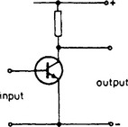
common-collector circuit A bipolar transistor circuit in which the input signal is applied between base and collector, and the output signal is derived from emitter and collector, the collector terminal thus being common to input and output circuits.
This circuit arrangement has a high input resistance and a low output resistance. Voltage gain is approximately unity but current gain can be considerable. The output signal is in phase with the input signal. Because of the unity voltage gain signals applied to the base emerge with negligible loss from the emitter. For this reason the circuit is often known as an emitter follower. The base form of the circuit is shown in Figure C.20. It is used where equipment requires a high input resistance or low output resistance and as a buffer stage.

common-emitter circuit (also known as grounded-emitter circuit (US)) A bipolar transistor circuit in which the input signal is applied between base and emitter, and the output signal is derived from the collector and emitter, the emitter terminal being thus common to input and output circuits. This form of connection gives a low input resistance and a high output resistance (although the ratio is not so high as for the common-base circuit). Current gain and voltage gain can be considerable. The output signal is in antiphase with the input signal. This is the most widely used of the three basic transistor circuits in analogue equipment probably because it is capable of greater output power than the others. The basic form of the circuit is shown in Figure C.21.
common-mode rejection ratio For a differential amplifier a figure of merit which assesses its ability to reject the same signal applied to both input terminals. An ideal differential amplifier responds only to the difference between the input signals so that there should be zero output for equal input signals. The ratio is best measured by use of alternating input signals to avoid difficulties caused by dc offset voltage.
common-mode signal The algebraic average of the two signals applied to the inputs of a differential amplifier. If the two inputs are of equal amplitude and are accurately in antiphase, the common-mode signal amplitude is zero. If, on the other hand, the two inputs are in phase, then their common amplitude is also that of the common-mode signal. A perfect differential amplifier does not respond to common-mode signals but see common-mode rejection ratio.
common return A return path that is common to two or more components or circuits; in electronic circuitry one of the supply lines often provides a common return.
communications receiver A radio receiver designed to cope with difficult transmission conditions. Such receivers usually have several wavebands, facilities for controlling the bandwidth of the IF amplifier, a BFO, an efficient a.g.c. system and, most importantly, a good signal-to-noise ratio.
compact disc (CD and CD-ROM) A disk, most often 5 inches in diameter, carrying a digital recording in the form of a series of minute bumps on a spiral path. The bumps are of the order of 1 μm in diameter and the face of the disc accommodates about 20000 tracks. The disc is replayed by a low-power laser beam which is reflected back along its incident path in the absence of a bump but is scattered if it strikes a bump. Servos are used to enable the laser beam to follow the tracks accurately, to keep the beam in focus on the disc surface and to maintain constant linear speed of the disk as it passes the beam (a master oscillator being used to provide a reference standard). As a consequence of the constant track speed, the rotational speed of the disc decreases from about 500 rpm to 200 rpm as the laser beam moves from its innermost to its outermost position.
Compact discs are used to record mono and stereo sound and the single recorded side gives a maximum playing time of about 75 minutes of stereo sound. A system of PCM is used to record the two sound signals and other signals associated with the servo systems. Sound reproduction from compact discs is greatly superior to that from conventional long-playing disks in freedom from distortion, signal-to-noise ratio, dynamic range and stereo separation.
A further advantage of CDs over other recording media such as long-playing records and tape is that there is no physical contact between the rotating disk surface and the reading head. There is therefore no wear on the disk. Consequently, unless it meets with some catastrophic accident, a CD should sound the same after thousands of playings as when it was new.
Compact discs are also widely used for the mass distribution of computer software. Known as CD-ROMs, these discs have a capacity of over 600 megabytes, much larger than that of floppy disks, facilitating the distribution of very large collections of software. For major software houses it is considerably cheaper to mass produce their software on CD-ROM than on floppy disks and this is sometimes reflected in software prices.
Other uses for compact disc include the storage of photographs (see Photo-CD) and video (see video disk).
companding The process of compressing a signal at one point in a communications system and of expanding at a later point to restore the original volume range. The process is used to improve the signal-to-noise ratio of the system and to be effective, the compression must take place before the point at which noise is introduced and expansion after that point. For example in a radio system the compressor is at the transmitter and the expander at the receiver, noise being introduced in the radio link. See compression, expansion.
comparator A circuit which compares two signals and gives an output indicating the result of the comparison.
comparator element Same as equivalence element.
compatibility (1) Of a colour television system that property which permits the colour signal to be reproduced by a normal black-and-white television receiver as a satisfactory black-and-white picture. (2) Of a stereophonic FM broadcasting system that property which permits the stereo signal to be reproduced by a normal monophonic receiver as a satisfactory monophonic signal.
compensation theorem If a linear network is modified by introducing an increment ΔZ in the impedance of one of the branches, the resulting current increment at any point in the network is equal to the current that would be produced at that point by a compensating voltage of –IΔZ acting in series with the modified branch. I is the current in this branch before modification.
compilation See computer language.
complementary metal-oxide-semiconductor (CMOS or COSMOS) A form of construction of logic monolithic integrated circuits using complementary insulated-gate field-effect transistors in pairs. The logic inverter stage illustrated in Figure C.22 is an example of a CMOS circuit.
complementary transistor logic (CTL) Logic circuits which make use of pnp and npn transistors.
complementary transistors pnp and npn transistors with similar characteristics. A positive signal applied to the base of an npn transistor increases the collector current but the same signal applied to the base of a pnp transistor decreases the collector current. Thus if the same signal is applied to the bases of a complementary pair of transistors, the transistors operate in push-pull without need for a phase-splitting circuit.
complex instruction set computer (CISC) A microprocessor having traditional architecture, capable of executing a wide repertoire of commands. The processors used in IBM PC-compatible computers are of this type. The alternative is a reduced instruction set computer (RISC), which has a limited repertoire of commands, but is faster.
compliance In a mechanical or acoustical oscillating system a property of a spring or similar component which enables it to oppose a change in applied force and is measured by the displacement caused by unit force. It is thus the reciprocal of stiffness. Compliance is analogous to capacitance in electrical oscillating circuits. A spring can store mechanical energy when it is compressed just as a capacitor can store electrical energy when it is charged.
composite colour signal (US) See synchronising signal.
composite signal (US) Same as video signal.
compound connection Same as Darlington pair.
compression (1) Reduction of the volume range of a signal by varying the gain to which it is subjected according to the mean volume level, the gain being greater for low signal volumes than for high signal volumes. Compression permits the transmission of higher mean volume levels thus improving signal-to-noise ratio. (2) In computing and data processing, the reduction of the size of files and therefore of their storage space requirement or transmission bandwidth. Various compression algorithms are used, according to the type of data in the file. Real-time compression and decompression processing is sometimes built into filing systems, greatly enhancing their effective capacity.
compression ratio The ratio, usually stated in decibels, of the gain at a reference signal level to the gain at a higher stated level. See compression.
computer An equipment which accepts information, carries out specified mathematical and/or logical operations upon it and supplies the required answer. Computers are sometimes called data-processing equipment. The information input must be in a form which the computer can accept and there are two principal types of computer, the analogue and the digital. See analogue computer, digital computer.
computer-aided design (CAD) The use of a computer, particularly with graphics, to assist in the design of engineering, structural or architectural projects. As an example of the interactive design possible by this means, three-dimensional representations of car bodies, building frameworks or printed-wiring-board layouts can be created and modified by the use of lightpens and mice.
computer-aided engineering (CAE) Generic term embracing computer-aided design and computer-aided manufacture.
computer-aided manufacture (CAM) Production of goods with the assistance of a computer or numerically-controlled machinery.
computer-aided software engineering (CASE) A technique used in some branches of computing, especially databasing and business modelling, in which the program is generated by a computer. The problem to be solved by the new program is defined using CASE tools which may employ a graphical user interface to indicate relationships between repository members and outside events. CASE is a much faster and more powerful technique than conventional programming for certain kinds of application.
computer control Operation in which the variables controlling a process are applied to a computer which carries out the required mathematical and/or logical operations on the inputs, the output of the computer being used to control the process.
computer language A combination of symbols, words and statements governed by a syntax and used to construct a computer program. Ultimately the central processing unit only understands a limited range of instructions—machine code or machine language—which it reads in binary form. The earliest method of programming involved writing machine code directly. This was a cumbersome task since it required an intimate knowledge of the processor and provided no assistance in error finding.
Today some applications and subroutines, especially those that involve intensive arithmetic, are still programmed in machine code because of its speed of execution. Instead of writing the program directly in machine code, however, a programming language called an assembler is used. This uses as source code a sequence of mnemonics which represent the processor instructions; these are easier to understand than the binary numeric codes themselves. The source code is written in a word processor or text editor and when finished is converted to executable machine code in a process called assembly. Because assembler source code inevitably is closely related to the machine code to which it is converted, an assembler is regarded as a low-level computer language.
For many applications computer programs are written in high-level languages such as C and BASIC in which the source code bears no direct relationship to the machine code that is ultimately executed. High-level languages use keywords to represent common operations such as displaying output on the VDU or searching text for a certain character sequence. They also allow the programmer to define subroutines or procedures for frequently used sequences of operations and these can be called as required from any point in the program. In most high-level languages the completed source code must be converted to executable machine code in a process called compilation before it can be executed. Some high-level languages, however, do not require compilation. Instead the source code itself is executed in real time by a program called an interpreter. Inevitably execution is slower than in a compiled language, but interpreted languages are interactive and easy to use; moreover run-time errors usually generate informative error messages such as ‘Variable not found at line 360’.
Some of the computer languages in common use are:
C and C++ A general-purpose compiled language using a rigid syntax and structure. One benefit is the comparative ease with which one set of source code can be differently compiled for use on computers having widely differing central processing units and operating systems.
BASIC (Beginner’s All-purpose Symbolic Instruction Code). English keywords and simple syntax make this one of the most widely-used languages, especially in microcomputers where it is generally interpreted rather than compiled.
Algol in which the instructions are presented in the form of algorithms.
FORTRAN (FORmula TRANslation) which is mainly used for instructions designed to solve mathematical or logic problems.
COBOL (COmmon Business-Oriented Language) intended for business and commercial use.
Forth used primarily for process control and scientific applications, is unusual in being a compiling language that is interactive. Forth consists of a dictionary of keywords and a compiler; applications are implemented by repeatedly defining new keywords in terms of the original or previously-defined keywords until one keyword is defined which embraces the entire application.
Pascal uses BASIC-like keywords in a very rigid and logical syntax. Because its use fosters an orderly and systematic approach to programming it is much used in education although originally developed for scientific applications.
Occam has been specially developed for use with transputers.
computer terminal An item of equipment at which data can be fed into a (possibly-remote) computer or can be received from it. The data may be fed in via a keyboard and may be received in alphanumeric or graphical form.
concentric line Same as coaxial cable.
concertina phase-splitter Circuit in which an active device is located at the midpoint of the load resistor so that equal and opposite signal voltages are developed at the anode (collector or drain) and cathode (emitter or source). Figure C.22 shows a pnp transistor used in such a circuit.

condenser An obsolete term for capacitor.

condenser microphone See electrostatic microphone.
conditional implication gate Same as IF-THEN gate.
conductance (G) The reciprocal of resistance and the real component of admittance. For a purely-resistive AC circuit, the voltage and current are in phase and the conductance is the ratio of current to voltage.
conduction band In an energy-level diagram the energy range of electrons which have broken free of the parent atom and can thus act as charge carriers, i.e. they can move freely under the influence of an electric field.
conduction cooling Of a device or equipment dissipating considerable power a method of removing heat by use of a heat sink in good thermal contact with the device. The heat sink may be a finned radiator or a prepared surface on a panel.
conductivity In general a term expressing the ability of a material to carry an electric current. More specifically conductivity is the reciprocal of resistivity. The conductivity of metals, for example, is better, i.e. lower than that of non-metals.
conductor Any element in a component or a circuit providing a path for the passage of electric current, e.g. the strips of copper on a printed circuit board.
conjugate impedances Two impedances with equal values of resistive component and in which the reactive components are equal but of opposite sign.
constant-amplitude recording In disk recording a characteristic for which constant-amplitude sinusoidal signals applied to the recording head give constant recorded amplitudes. See constant-velocity recording.
constant-current characteristics Graphical relationship between the voltages at two electrodes of an electron tube necessary to maintain the current at one of them constant. The term is generally applied to the Va–Vg characteristics of an electron tube for constant Ia which are used in assessing the performance of high-power triodes as output stages in transmitters.
constant-current modulation Same as Heising modulation.
constant-k filter A ladder network composed of reactances, the series reactances being of opposite sign to the shunt reactances. Because positive (i.e. inductive) reactance is directly proportional to frequency and negative (i.e. capacitive) reactance is inversely proportional to frequency, the product of the series and shunt reactances is independent of frequency. The constancy of this product has given this type of filter its name.
Constant-k filters may be low-pass, high-pass, band-pass, etc. types but the steepness of fall-off in response at the edges of the passbands is not good and the characteristic impedance is not constant over the passband so that a purely-resistive termination is not satisfactory. Both disadvantages can be overcome by the inclusion of m-derived sections or half-sections. See m-derivation.
constant luminance system A colour TV system in which the brightness of the reproduced picture depends solely on the transmitted luminance signal and is unaffected by the chrominance signal transmitted with it. This is an ideal which is not perfectly achieved in the NTSC, PAL and SECAM colour television systems currently in use.
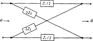
constant-resistance network A network which, when terminated in a pure resistance of value R, gives an input resistance of R which is independent of frequency. Attenuators and equalisers are usually designed as constant-resistance networks so that they can be inserted in circuits without affecting resistance terminations. An example of a constant-resistance network is the lattice network of Figure C.24 in which Z1Z2 must equal R2. Z1 and Z2 must hence be inverse impedances to give the desired constant-resistance property.
constant-velocity recording In disk recording a characteristic for which constant-amplitude sinusoidal signals applied to the recording head give constant recorded velocities, i.e. the recorded amplitude is inversely proportional to frequency. In practice such a characteristic cannot be used over the whole of the audio spectrum because of the possibility of exceeding the groove spacing at low frequencies and giving inadequate signal-to-noise ratio at high frequencies. Moreover the chosen characteristic must take into account the fact that sound amplitudes are smaller at high frequencies than at low. Practical recording characteristics tend therefore to be a compromise between constant amplitude and constant velocity. See constant-amplitude recording.
contact The conductive areas which touch to establish continuity in a switch or a relay.
continuity A continuous low-resistance electrical path between two points.
continuous wave (CW) Radio waves of constant amplitude and frequency. The transmission and reception of such a wave establishes a link between transmitter and receiver but to enable information to be sent over the link the continuous wave (carrier wave) must be keyed on and off in accordance with a code (e.g. Morse) or must be modified in amplitude, phase or frequency, i.e. must he modulated. See interrupted continuous wave, modulation.
contrast (1) In sound transmission the dynamic range, i.e. the ratio of the loudness of the loudest to the quietest passages in a programme. This range must be compressed before a sound programme can be recorded or transmitted. Methods of expansion are available to re-establish the original dynamic range. (2) In TV, the ratio of the brightness levels of two parts of a displayed picture. It is determined by the amplitude of the video signal input to the picture tube and hence by the gain of the preceding amplifiers.
contrast gradient Same as gamma.
control code An ASCII character in the range 0 to 31. Such characters represent instructions to perform some operation on the output device rather than printable characters. For example code 7 (‘BEL’) emits a beep and code 9 (‘TAB’) moves the insertion point to the next tab stop. From a keyboard these codes may be issued by using the Ctrl key in conjunction with alphabetic and other keys.
control grid An electrode situated between the cathode and the other electrodes of an electron tube, the potential of which determines the magnitude of the electron current flowing from the cathode to the other electrodes. The control grid is usually situated very close to the cathode and is constructed in the form of a wire spiral the pitch of which can be adjusted during manufacture to give the required degree of control over the density of the electron stream. Thus the pitch of the grid determines the mutual conductance of the tube. In a cathode ray tube the control grid (sometimes known as the modulator) is often in the form of a disk containing a small aperture through which the electron beam passes.
control impedance Same as unilateral impedance.
controller In computers and data-processing equipment an item of hardware which controls the operations of peripheral units according to instructions from the central processor.
controlled-carrier modulation Same as floating-carrier modulation.
controlled silicon rectifier (CSR) Same as thyristor.
control ratio In a thyratron the slope of the characteristic relating the anode voltage with the critical grid voltage. Figure C.25 shows that the characteristic has a long linear section showing that the control ratio is constant over a wide range of operating voltages.

control unit Of a digital computer that section which is responsible for interpreting and acting upon the input instructions and for applying signals to the arithmetic unit and other sections of the computer to enable it to carry out the allotted task.
convection cooling Of a device or equipment dissipating considerable power a method of removing heat which relies on natural convection and radiation from the device. An adequate clear space must be provided around the device for this method to be successful.
convergence In a colour picture tube the adjustments which ensure that the three primary colour images are correctly superposed.
conversion conductance (gc) or conversion transconductance (US) The ratio of a small change in the wanted-signal component in the output current of a frequency changer to the small change in signal-frequency input voltage which gives rise to it under specified operating conditions.
converter General term for an equipment which changes: (1) The nature of a current, e.g. an AC to DC converter (a device changing DC to AC is usually known as an inverter). (2) The voltage of a power supply, e.g. one converting a 12 V DC supply into 240V DC. (3) The frequency of a signal, e.g. the frequency changer in a superheterodyne receiver. (4) The form in which information is coded, e.g. a television standards converter which converts a 525-line signal into a 625-line version of the same picture.
coprocessor An additional processor in a computer designed to carry out specific functions, such as mathematical operations or handling graphical output, relieving the burden on the main processor.
cordless telephone A telephone in which the link between the handset and the base is by radio, both containing transceivers. The advantage is that the user may roam freely within the unit’s range during a telephone conversation. The handset is powered by an internal rechargeable battery which is recharged when it is plugged into the base unit; this requires a mains supply.
corona discharge Visible discharge of electricity surrounding a charged conductor when its potential exceeds the critical value at which the surrounding air is ionised. The discharge is often accompanied by a hissing noise and becomes more marked as the radius of curvature of the conductor is reduced. Sharp points, therefore, give pronounced corona discharge and to minimise the effect the surface of the conductor must be smooth.
counterpoise Same as artificial earth.
counting The process of deriving one output pulse for every n input pulses. If n = 2 the device is a binary counter and if n = 10 it is a decade counter. If the input pulses are at regular intervals the device is more properly known a frequency divider. Usually a counter is a circuit which can take up a number of different states and which changes from one state to another in a particular sequence each time an input pulse is received.
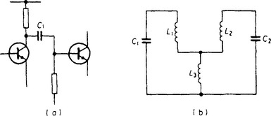
coupling Any means whereby power can be transferred from one circuit to another. The circuits may be physically separated, power being transferred between them by magnetic or capacitive means, or they may be connected, power being transferred via components common to both circuits. The common component can be in series as C1 in Figure C.26 (a) or in shunt as L3 in Figure C.26 (b).
coupling coefficient (k) A quantitative measure of the degree of coupling between two circuits. It is equal to the ratio of the mutual impedance (resistive, inductive or capacitive) between the circuits to the geometric mean of the two impedances of like kind in the two circuits. The maximum possible value of k is unity and values used in practice are often as low as 0.01.
If two tuned circuits L1C1 and L2C2 are coupled by mutual inductance M as shown in Figure C.27 (a) the coefficient of coupling is given by
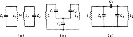
Figure C.27 Examples of coupling by (a) mutual inductance, (b) shunt capacitance and (c) series capacitance. The coupling coefficient for each circuit is given in the text
and if the two circuits are identical L1 = L2 = L, so that
For shunt-capacitance coupling shown in Figure C.27 (b) the coefficient of coupling is given by
in which C1 and C2 are assumed small compared with C3. If C1 = C2 = C
For series-capacitance coupling shown in Figure C.27 (c) provided C1 and C2 are large compared with C3, the coefficient of coupling is given by
approximately and if C1 = C2 = C
The examples given are of intentional power transfer, but coupling is sometimes unwanted because it can give rise to instability or oscillation. To avoid such coupling it may be necessary to employ electric or magnetic screening or decoupling.
covalent bonds The bonds between two similar atoms which share two electrons, one from each atom. This occurs in the tetravalent atoms of germanium and silicon which therefore behave in some respects as though they had eight electrons in the outermost shell. This is sufficient to fill the shell which accounts for the very low electrical conductivity of pure germanium and silicon.
CPS emitron tube Same as orthicon.
crash In computers and data processing equipment, an error which results in total loss of control of the system. A common cause is that the processor begins executing an endless loop of instructions to which the user has no input. To the user, the system often appears to ‘freeze’. His only recourse is to reset and restart the system. Any processed data that had not been stored at the time of the crash is usually lost irretrievably.
critical coupling The degree of coupling between two circuits tuned to the same frequency which permits maximum transfer of energy from one to the other at the resonance frequency. For degrees of coupling smaller than the critical value the combination has a single-peaked response curve and for degrees of coupling greater than critical the frequency response has two peaks equidistant from the resonance frequency, the peak separation increasing with increase in coupling as shown in Figure C.28. Coupled circuits giving a two-peaked response, with the peaks near to the resonance frequency, are often employed as bandpass filters in RF and IF amplifiers in a receiver. The critical value of the coupling coefficient is given by
where Q1 and Q2 are the Q values of the two tuned circuits. If the circuits are identical and Q1 = Q2 = Q
Thus if Q = 100, a common value, the critical value of k is 0.01.

Figure C.28 Response curves for two identical tuned circuits showing the effect of varying the degree of coupling
critical damping The condition where the rate of loss of energy is just sufficient to prevent free oscillation of an oscillating system. For a resonant electrical circuit the value of series resistance which gives critical damping is equal to 2√(L/C). As an example of a mechanical system the friction in the moving parts of a measuring instrument is commonly adjusted to give critical damping so that the pointer takes up its final reading very quickly and without overshoot (which is the start of oscillation).
critical grid current In a thyratron the value of the grid current corresponding to the critical grid voltage.
critical grid voltage In a thyratron with a particular value of anode voltage the minimum value of grid voltage at which anode current begins to flow. The value of the critical grid voltage depends on the anode voltage, becoming less negative as the anode voltage is reduced as shown in Figure C.25.
critical-space tetrode A tetrode in which the spacing between screen grid and anode is large so that the negative charge of the electron stream in it at any instant is sufficient to act as a suppressor grid and so prevent secondary electrons released from the anode from reaching the screen grid. In this way the tetrode kink can be eliminated so improving the ability of the tube to handle large output voltage swings.
cross coupling Unwanted coupling between two signal paths which can result in crosstalk.
cross modulation Transfer of the modulation of one signal to another. In AM reception this can be caused by non-linearity in RF stages. As a result the carrier of a wanted signal becomes modulated by the unwanted modulation of another signal.
crossover distortion In a class-B amplifier, waveform distortion caused by too low a value of standing current. It takes the form of a discontinuity at the datum level of a sinusoidal signal as shown in Figure C.29 caused by the slight delay which occurs whilst each half of the output stage takes over from the other. See class-B operation.

crossover frequency (1) In dividing networks the frequency at which equal power is delivered to each of the adjacent frequency channels (assumed correctly terminated). It is the frequency, in fact, at which the signal crosses over from one channel to the other. In two-unit loudspeakers the crossover frequency is usually between 500 Hz and 2 kHz. (2) See turnover frequency.
crossover network Same as dividing network.
crossover voltage In cathode ray tubes the voltage of a secondary-emitting surface at which the secondary emission ratio is unity.
There are generally two such voltages as shown at V1 and V2 in Figure C.30. From Figure C.30 it is possible to predict the voltage at which the target of a TV camera tube or the screen of a CRT will stabilise. For example if the initial target potential is below V1 the secondary emission ratio is less than unity and the number of electrons striking the target exceeds those lost from it. Thus the target potential is driven negative until it stabilises at a potential near that of the electron-gun cathode. This is the type of target stabilisation used in all low-velocity camera tubes.

If, however, the initial target potential is between V1 and V2 and if the final anode potential of the electron gun is also between these two voltages then the secondary emission ratio is greater than one and the target releases more electrons than it gains from the electron beam. If the target potential is initially below that of the final anode all the secondary electrons released are collected by the final anode and the target potential rises until it is approximately equal to that of the final anode. If the target potential is initially above that of the final anode the retarding field between target and anode returns the secondary electrons to the target and the target potential falls until again it is approximately equal to the final anode potential. This is the type of stabilisation which occurs in high-velocity TV camera tubes and in cathode ray tubes.
crosstalk Unwanted signals appearing in one signal path as a result of coupling with other signal paths. An example is the induction of unwanted speech signals into one pair of conductors from neighbouring pairs in a telephone cable.
crowbar circuit Protective circuit which, in the event of a fault that could damage equipment by excessive voltage or excessive current, applies a short circuit across the supply to the equipment, causing the fuses to blow or a cut-out to operate thus isolating the equipment from the supply. The short-circuiting device must have very low resistance when triggered into conduction by the fault-detecting circuit and may be, for example, a thyratron or a thyristor.
cryogenics The study of the properties of devices at temperatures near absolute zero (−273°C or 0°K). See superconductivity.
cryotron (cryogenic store) A store which makes use of the ability of a magnetic field to control the transition from the normal to the superconductive state of resistive elements.
crystal See piezo-electric crystal.
crystal-controlled oscillator See crystal oscillator.
crystal diode A semiconductor crystal in contact with a metal probe (see point-contact diode) or two different types of semiconductor crystal in contact (which may be regarded as a crude form of junction diode). These were used for detection in the early days of broadcasting and successful results depended on finding and retaining sensitive points on the crystal surfaces. See cat’s whisker, crystal receiver.
crystal filter A filter network containing one or more piezo-electric crystals as frequency-determining elements. The resonant properties of the crystals are used when the filter is required to accept or reject a narrow band of frequencies.
crystal growing See crystal pulling.
crystal loudspeaker A loudspeaker which relies for its action on the piezo-electric effect. The AF signal is applied to a crystal bimorph and the resulting vibrations of the bimorph are mechanically coupled to the diaphragm. Such loudspeakers generally operate over a limited frequency range at the upper end of the AF spectrum and form one unit (the tweeter) of a multi-unit loudspeaker. The graphical symbol for a crystal loudspeaker is given in Figure C.31 (a).
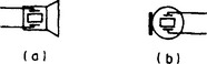
crystal microphone A microphone which relies for its action on the piezo-electric effect. In one type the sound waves strike a diaphragm and the resulting mechanical vibrations are coupled to a crystal bimorph. The voltages developed across the faces of the bimorph constitute the microphone output. In another type of crystal microphone there is no diaphragm and the sound waves impinge directly on a sound cell which consists of two crystal bimorphs mounted back-to-back. The graphical symbol for a crystal microphone is given in Figure C.31 (b).
crystal oscillator An oscillator the frequency of which is controlled by a piezo-electric crystal usually of quartz. Such oscillators have great stability and are used as frequency standards, in signal generators and as master oscillators in radio transmitters.
crystal oven A thermostatically-controlled oven containing a crystal-controlled oscillator. By maintaining it at a constant temperature, a crystal oscillator can give very high frequency stability. Such ovens have been used in broadcasting transmitting stations to achieve the required stability of carrier frequency.
crystal pickup A disk-reproducing head which relies for its action on the piezo-electric effect. The movement of the stylus point caused by the groove modulation is coupled to a crystal bimorph and the voltage developed between its opposite faces constitutes the pickup output. A stereo pickup includes a mechanical device for resolving the movement of the stylus into two directions at right angles to each other, each movement driving a separate bimorph. The symbol for a crystal pickup is given in Figure C.32.
crystal pulling A method of producing large single crystals such as are required in the manufacture of semiconductor devices by slowly withdrawing a developing crystal from the molten semiconductor material.
crystal receiver (1) A radio receiver comprising a tuned circuit, a crystal detector and a pair of headphones. A typical circuit diagram for such a simple receiver is given in Figure C.33. Receivers of this type were commonly used in the 1920s, before electron tubes were available, for the reception of broadcast programmes. They required no batteries or mains supply, the AF output depending on the magnitude of the signal picked up by the receiving antenna. A high outdoor antenna was therefore desirable for good results. (2) A waveguide incorporating a crystal diode and used for the detection of received radio signals.
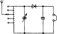
crystal set Same as crystal receiver (1).
crystal triode Early name for transistor.
cumulative grid detector Same as grid-leak detector.
current A unidirectional movement of charge carriers. In a conductor the current is a drift of electrons towards the positive pole of the applied electric field. In a semiconductor, in addition to the electrons moving to the positive pole, current is also carried by holes moving in the opposite direction. In vacuum electron tubes current is again carried by electrons attracted to the anode: such currents are sometimes called convection currents. In a gas-filled tube ionisation causes the medium to divide into positive and negative ions which move towards the cathode and anode respectively. A similar process occurs in electrolytes as a result of dissociation. There is, however, no division into charged particles in the displacement current, a hypothetical concept introduced to explain the passage of alternating current through the dielectric of a capacitor.
current amplification factor Of a bipolar transistor the ratio of a small change in output current to the change in input current which gives rise to it. In a common-base circuit the current amplification factor relates changes in collector current with changes in emitter current: this is represented by α or hfb and is necessarily less than unity. In a common-emitter circuit the current amplification factor relates changes in collector current with changes in base current. This is represented by β or hfe and practical values may lie between 10 and 500. α and β are related thus
current amplifier A circuit incorporating one or more active devices and designed to amplify current waveforms. The term distinguishes such amplifiers from those designed to amplify voltage waveforms or to deliver power to a load. It is the ratio of source impedance to input impedance and of output impedance to load impedance which determines whether a device or amplifier is best regarded as a current amplifier, voltage amplifier or power amplifier. If both ratios are large compared with unity the signal transferred from source to input and output to load is best regarded as a current waveform. The associated signal voltage waveform in a current amplifier is of minor interest and is usually of small amplitude. Because bipolar transistors have a low input impedance and a high output impedance they are usually regarded as current amplifiers.
current dumping An amplifying technique in which a class-A stage feeds the output load at low signal levels, a class-B stage taking over progressively as signal level increases, an overall negative feedback system ensuring linearity. The class-B stage is regarded as a current dumper.
current feedback A negative feedback system in which the feedback signal is directly proportional to the current in the load. The feedback signal may be derived from a resistor in series with the load as shown in Figure C.34, the resistor being small compared with the value of the load. A simple way of applying current feedback to an active device is to omit the decoupling capacitor which is normally connected across the cathode or emitter bias resistor. The effect of current feedback is to improve linearity, decrease gain and to increase the effective output resistance of the active device driving the load, i.e. it tends to make this device a constant-current source. See voltage feedback.
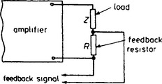
current mirror A circuit arrangement in which a current in one of a pair of matched active devices causes an equal current in the other. In the basic form of the circuit shown in Figure C.35 the current Ic1 in TR1 is determined chiefly by the supply voltage and the value of R1. This sets up a particular value of base-emitter voltage in TR1 (dependent on the type of transistor and its temperature) which is directly communicated to the matching transistor TR2 causing an equal collector current Ic2 in R2. If TR2 is replaced by a number of transistors in parallel their total collector current is equal to Ic1. This technique is used in integrated circuits to adjust and stabilise the currents in the individual transistors.

current mode logic (CML) A form of logic giving high switching speed and good immunity from noise, particularly from disturbances on the supply line. It employs bipolar transistors arranged in balanced pairs and fed with complementary input signals. The supply to each pair is via a series transistor arranged to maintain a constant current.
cursor The symbol, often a flashing character-sized block, that shows where on a VDU the next character to be typed will appear.
cut-off attenuator A length of waveguide used at a frequency below its cut-off frequency to introduce non-dissipative attenuation which can be controlled by adjusting the length of the waveguide.
cut-off frequency (1) Of a filter the upper or lower limit of a passband. Outside the passband the attenuation should ideally increase rapidly and the cut-off frequency is sometimes defined as the frequency at which the attenuation is 3 dB as shown for a lowpass filter in Figure C.36. (2) Of a waveguide for a given mode of transmission the frequency below which transmission of RF signals along the guide is not possible. The cut-off frequency depends on the mode and on the cross-sectional dimensions of the waveguide.
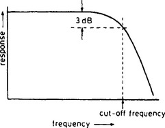
cycle An interval of space or time in which a periodically varying quantity completes one set of changes of the variable. For a sinusoid a cycle contains one complete set of positive values followed by an equal set of negative values.
cyclic code Same as Gray code.
cyclic store A store to which access is available only at fixed intervals during a cycle, e.g. a magnetic drum.
cylinder The position of one track on a floppy or hard disk. The term originates from its use on hard drives consisting of a number of disks on a common spindle. Each disk contains two tracks at that position, one on each side. Consequently that position, repeated for each disk on the spindle, could be considered as constituting a hypothetical cylinder. A cylinder-shaped symbol, as shown in Figure C.37, is widely used in the computer industry to represent mass storage.
