I
icon Small graphical representation displayed on the screen to illustrate a computer function. For example, a representation of a file folder to indicate a directory.
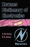
iconoscope The earliest form of TV camera tube in which the optical image of the scene to be televised is focused on a photo-emissive target mosaic which is obliquely scanned by a high-velocity electron beam.
The mosaic is deposited on one face of a mica sheet which is backed by a conductive signal plate from which the output of the tube is taken. When the optical image is focused on the mosaic, photo-electrons are released from each element in proportion to the light falling on it. Thus a positive charge image is built up on the mosaic surface and this grows with time as the capacitance between element and signal plate is charged. The charge image is discharged by the scanning beam and the resulting voltage change is transferred to the signal plate via the capacitive coupling to the mosaic.
In spite of the charge storage thus achieved the tube is not very sensitive and required high scene illumination for a satisfactory signal-to-noise ratio. Moreover secondary emission from the target as a result of bombardment by the high-velocity scanning beam results in spurious signals in the tube output which produce undesirable shading effects in reproduced images. These effects were minimised by mixing with the tube output, sawtooth and parabolic waveforms at line and field frequencies.
One example of an iconoscope is the standard emitron tube, the construction of which is illustrated in Figure I.1; this is the type of tube used when Britain started the world’s first regular high-definition TV service from Alexandra Palace in North London towards the end of 1936.
ideal radiator Same as full radiator.
identity gate Same as AND gate.
IF-THEN gate A gate with two inputs and one output such that the relationship between inputs and outputs is given in the following truth table:
| input 1 | input 2 | output |
| 1 | 1 | 1 |
| 1 | 0 | 0 |
| 0 | 1 | 1 |
| 0 | 0 | 1 |
igniter (also known as ignition electrode) In a mercury-pool discharge tube a stationary electrode which is in contact with the mercury pool and, when suitably biased, causes a local hot spot on the surface so initiating the main discharge.
ignition voltage Same as firing voltage.
ignitron A gas-discharge rectifier tube with a mercury-pool cathode and a single anode capable of a large current output. The arc is initiated by an ignition electrode which dips into the mercury pool. A positive voltage is applied to the igniter once per cycle of the applied alternating voltage and this causes a small arc at the mercury surface which precipitates the main discharge.
image attenuation coefficient (or factor) See image transfer coefficient.
image converter An electron tube in which an image of a scene focused on a photo-cathode gives rise to a corresponding visible image on a fluorescent screen. One advantage of such a tube is that the photo-cathode may be made sensitive to infra-red radiation and can thus give a visible image of a scene invisible to the human eye.
image dissector An early form of TV camera tube in which an optical image of the scene to be televised is focused on a photo-cathode, the released photo-electrons forming an electron image which is focused on the plane of a defining aperture and is swept over the aperture to effect scanning.
The defining aperture was a hole in an anode and electrons passing through it were either intercepted by a collector electrode or were directed into an electron multiplier. The tube lacked sensitivity because of the absence of any form of charge storage but it was used for transmitting cinema film where a large light input could be achieved.
image frequency In superheterodyne reception a frequency as much above (or below) the oscillator frequency as the wanted signal frequency is below (or above) it and which is therefore accepted with the wanted signal by the IF amplifier so causing interference.
image iconoscope An early form of TV camera tube consisting of an iconoscope with an image section.
image impedances Two parameters of a two-terminal-pair network such that if the output is terminated with an impedance Z2 the input impedance is Z1 and if the input is terminated with a impedance Z1 the output impedance is Z2.
Networks are used on an image-impedance basis for matching purposes. For example if an amplifier requires a load of impedance Z1 in order to perform properly and if the load to be fed has an impedance Z2, then a network with image impedances Z1 and Z2 can be used to connect the amplifier to its load. In this way the equipment has an effective load impedance of Z2 and the load is effectively supplied from a generator of impedance Z2: in other words correct matching is achieved at the input and the output of the network.
If the network contains inductance and capacitance then it is possible that the image impedances will be correct at only one frequency. A transformer can achieve matching over a wide frequency range.
image interference In superheterodyne reception interference from signals on the image frequency. The frequency of such interfering signals differs from that of the wanted signal by twice the intermediate frequency and, to minimise image interference, the signal-frequency circuits of a superheterodyne receiver are designed to give great attenuation at the image frequency.
image isocon An image orthicon in which the output is obtained from an electron multiplier into which the electron beam scattered from the target is directed. When the scanning beam strikes the target some electrons are absorbed to neutralise the charge image, others return to the electron gun and the remainder are scattered. It is the scattered, not returned, electrons which are captured and directed into the electron multiplier in the image isocon.
image orthicon An orthicon TV camera tube with an image section and in which the output signal is obtained from an electron multiplier into which the return scanning beam is directed.
The essential features of the tube are illustrated in Figure I.2. An optical image of the scene to be televised is focused on the photo-cathode and the photo-electrons so released are focused by a combination of electrostatic and magnetic electron lenses on the image-section face of the target where they give rise to secondary emission which is collected by the nearby positively-charged mesh.

Thus a positive charge image is established on the face of the target. If the tube is directed at a very bright light causing the target potential to exceed that of the mesh, the excess secondary electrons are returned to the target: in this way the mesh keeps the tube stable for all light inputs.
The target is very thin and the charge image is rapidly transferred to the opposite face which is scanned by the low-velocity beam. The beam lands on the target to neutralise the positive charge image and thus the return scanning beam is amplitude modulated by the required picture signal. The return beam is directed into the input of a multi-stage electron multiplier which surrounds the electron gun.
The tube is extremely sensitive and is capable of high-quality pictures. It is, however, complex and too bulky (typically 15 in long and 3 or 4½ in diameter) to be used in colour cameras where three or four tubes are necessary.
image phase-change coefficient (or constant) See image transfer coefficient.
image processing The application of digital processing to bitmapped images, such as scanned photographs or digitised video, to change their appearance. Often the processing is to improve the appearance, e.g. by improving the contrast in an underexposed photograph, but sometimes the intention is the reverse, e.g. to reduce the number of colours in the image in order to achieve some special effect.
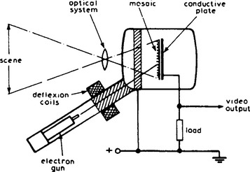
image section An electron-optical stage included in some television camera tubes to increase sensitivity. As shown in Figure I.3 the optical image is focused on the photo-cathode in the image stage and the liberated photo-electrons are focused on the target to form a charge image by secondary emission from the target. The use of an image section thus separates the functions of photo-emission (now carried out by the photo-cathode) and secondary emission (carried out by the target). In the iconoscope the target is required to carry out both functions.
image transfer coefficient (or constant) For a network terminated in its image impedances at both ends, one half the natural logarithm of the complex ratio of the steady-state volt-amps entering the network to the volt-amps leaving the network.
The real part of the image transfer coefficient is known as the image attenuation coefficient and the imaginary part as the image phase-change coefficient or, more simply, the image phase coefficient.
When networks are connected in cascade on an image basis the image attenuation coefficient of the group is equal to the sum of the image attenuation coefficients of the individual networks and the image phase coefficient of the group is equal to the sum of the sum of the individual phase coefficients.
For a symmetrical network the real and imaginary parts of the image transfer coefficient are equal to the real and imaginary parts of the propagation coefficient.
immersion lens In a cathode ray tube, an electrostatic electron lens designed to concentrate the electrons liberated from the cathode into a beam. Because these electrons have very low velocities the lens is situated very close to the cathode, so close in fact that the cathode may be regarded as immersed in the lens. The lens usually consists of two plates containing apertures and which may have cylindrical extensions.
immitance A term which can mean impedance or admittance. It is used in network theory where the distinction between impedance and admittance is irrelevant.
impact dot-matrix printer See printer.
impact ionisation The liberation of orbital electrons from an atom in a crystal lattice as a result of a high-energy collision.
impatt diode A four-layer semiconductor device of pnin construction used as a microwave oscillator. A reverse bias causes avalanche breakdown at the pn junction. Electrons cross the i-region which acts as a drift space and the transit time is arranged to be one half the period of the required oscillation. The device then has a negative resistance and, given a suitable resonant load, can give up to 50 W output at 10 GHz.
impedance (Z) In general an indication of the opposition offered by a circuit to a flow of alternating current in it. More specifically it is the ratio of the alternating EMF applied to the circuit to the resultant current flowing in it. As there is normally a phase difference between the voltage and the current, the impedance Z is complex and can be written
where R, the real component of the impedance is the resistance of the circuit and X, the imaginary component is the reactance of the circuit. The numerical value of the impedance is given by
and can be calculated by dividing the RMS applied voltage by the resulting RMS current. The impedance concept is useful in solving problems where components are connected in series because in such circuits resistances can simply be added to give the total or effective resistance and reactances are added or subtracted depending on their sign.
impedance matching The process of ensuring that two impedances are equal. This is important for two reasons: (1) To ensure that maximum power is transferred from a generator to a load, the generator and load impedances must be matched. To do this over a wide frequency range the resistive and reactive components of the load impedance must in effect be made to equal those of the generator, e.g. by the use of a transformer. If, however, matching is necessary at only one frequency then maximum power transfer occurs when the load impedance is in effect made to equal the conjugate of the generator impedance, i.e. the resistive components are equal, the reactive components are equal in magnitude but opposite in sign. (2) To ensure that there is no reflection at the termination of a transmission line or filter network the termination must in effect be equal to the characteristic impedance of the line or the iterative impedance of the network.
imperfection Of a crystal, any difference in its structure from that of the ideal crystal. As an example an atom may be missing from a site or a site may be occupied by a foreign atom. Imperfections are responsible for hole and electron conduction.
import In computing to introduce data into an application in a format that is foreign to that application. For example, to introduce a bitmap into a vector graphics application.
impurity In semiconductor technology a foreign element added in minute but controlled quantities to a semiconductor element to give it the required p-type or n-type conductivity. In semiconductor compounds an excess or deficiency of an element belonging to the compound.
impurity diffusion See diffusion.
inclusion gate Same as IF-THEN gate.
inclusive-OR gate Same as OR gate.
incremental permeability The ratio of the change in magnetic flux density to the small change in magnetising force which gives rise to it when this is superimposed on a steady magnetising force.
independent sideband transmission (ISB) A system of amplitude modulation in which one sideband is produced by modulation by one signal and the other sideband is produced by modulation by a different signal. The system is not greatly used largely because of the difficulty of separating the two signals at the receiver.
indirectly-heated cathode A cathode of an electron tube for which the heat necessary for the thermionic emission is supplied by an independent heater contained within the cathode but insulated from it. The cathode is usually a nickel cylinder coated with electron-emitting material and the heater is a tungsten spiral or hairpin within it but insulated from the cylinder by, for example, aluminium oxide.
induced current A current flowing in a circuit as a result of an induced EMF.
induced EMF The EMF generated in a circuit as a result of electromagnetic induction.
inductance (L) In general that property of a current-carrying circuit which enables it to generate an EMF in itself (or in a nearby circuit) as a result of changes in the current and therefore in the associated magnetic field. The direction of the induced EMF is such as to oppose the change in current which gave rise to it and thus inductance may be regarded as the electrical analogue of inertia. The EMF induced in the circuit itself is more properly ascribed to self-inductance and that induced in a nearby circuit to mutual inductance. Clearly the inductance of a conductor can be increased by coiling it so as to increase linkage with the magnetic field and the introduction of a magnetic core increases it further. The practical unit of inductance is the Henry (H) and a circuit is said to have an inductance of one Henry if a current, changing at the rate of one ampere per second, induces an EMF of one volt in it.
induction See electromagnetic induction, magnetic flux density.
induction loop In general any looped conductor used to transfer energy to another by mutual inductance. More particularly, a form of localised wireless broadcasting used in churches, theatres, museums and other public buildings to assist those hard of hearing or to provide a commentary. They are also sometimes installed in the homes of partially deaf people to help them to hear radio and television programmes. The induction loop surrounds the area to be served and is connected to the output of an audio amplifier reproducing the required audio programme. Receivers are either hearing aids fitted with suitable pick-up coils (selected on the so-called ‘T’-switch) or dedicated receivers usually fitted with an earphone that the user holds against his ear.
inductive coupling Coupling of two circuits by virtue of a common inductor or by mutual inductance. The common inductor may be a series-connected component as in Figure I.4 (a) or a shunt component as in (b). Figure I.5 shows coupling by mutual inductance M.


inductor A component used because of its inductance. A wide variety of types of inductor are used in electronics. At low and audio frequencies inductors of many Henries consists of windings with laminated ferromagnetic cores. At higher frequencies eddy-current losses become important and non-conductive ferrite cores are used in RF conductors and transformers.
inertance That property of an acoustical vibrating system which enables it to resist changes in velocity. It is a function of the mass of the medium in the system, being given by m/A2, where m is the mass and A is the cross-sectional area over which the driving pressure acts. Inertance is the acoustical analogue of inductance.
infinite baffle A loudspeaker cabinet which is totally enclosed at the rear so that sound radiated from the rear of the diaphragm cannot interfere with forward-radiated sound. The cabinet therefore behaves as a baffle of infinite dimensions. In a practical design provision must be made to absorb the rear radiation from the diaphragm and allowance must be made for the inevitable raising of the fundamental resonance frequency of the loudspeaker caused by the stiffness of the air trapped in the cabinet. Nevertheless some very successful designs have been produced, some so small that the cabinet can be readily accommodated on a bookshelf or a mantlepiece.
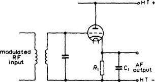
infinite-impedance detector An anode-bend detector in which the load is connected in the cathode circuit. A typical circuit diagram for the detector is shown in Figure I.6. The load R1 and associated capacitor C1 behave as in a diode detector circuit, i.e. C1 is charged on positive-going half-cycles of carrier input and discharges through R1 during negative-going half-cycles, so developing the AF waveform across the combination. The reactance of C1 is very high at AF and thus the tube has 100% negative feedback. No grid current flows and the input of the tube is very high, imposing negligible damping on the tuned circuit.
information superhighway A vague term denoting any network over which information in a variety of formats is accessible to a wide public. It is sometimes used to refer to the Internet although equally applicable to many other networks including interactive video on demand systems.
Information Technology (IT) A vague term embracing all electronic equipment that is used in the processing and presentation of data.
infra red Electromagnetic waves with frequencies extending from the red end of the visible spectrum to the microwave region (see Figure E.7). The radiation is invisible but gives a sensation of heat and is used in cooking and industrial heating applications as well as in remote control systems.
inhibiting signal A signal which prevents a particular action occurring. For example it may close a gate to prevent any output which might otherwise occur. An inhibiting signal is a negated enabling signal.
in-line colour picture tube See precision-in-line colour picture tube.
input (1) Of a device or equipment, the signal applied to it and upon which it performs some function, e.g. amplification. (2) The terminals to which the input signal is applied.
input impedance Of a device or equipment, the impedance it presents to the source of input signal.
insertion gain (or loss) The gain resulting from the insertion of a network between a generator and its load. It is given by the ratio (usually expressed in decibels) of the power (voltage or current) delivered to the load before insertion to the power (voltage or current) delivered after insertion.
insertion signal In TV a signal inserted into one of the line periods during the field blanking period. The signal is not seen on the screens of viewers’ receivers and is used by the transmitting authority to transmit information such as the source of programme or control data. The signal is also used for test purposes to give information on the performance of the television links. Of a television waveform, a signal introduced during flyback periods to carry information for engineering purposes or for display on receiver screens, e.g. teletext.
instability Generation of unwanted and sustained oscillations.
instrument transformer A transformer giving at its secondary winding a voltage or current which is precisely related in magnitude and phase with that at the primary winding and is therefore suitable for application to a measuring instrument or a control or protective device.
insulated-gate field-effect transistor (IGFET) A field-effect transistor in which the input electrode is capacitively coupled to the channel. A cross section of an IGFET is given in Figure I.7. It consists of a base layer of p-type silicon with diffused n-regions at each end to which source and drain connections are made. During manufacture by the planar process, the device is sealed by a layer of silicon dioxide obtained by heating it to 1200° in an atmosphere of water vapour or oxygen. A thin layer of aluminium is then deposited on the device to provide a gate connection, the aluminium, silicon dioxide and the p-layer forming a capacitor.

Figure I.7 Simplified diagram showing the structure of an n-channel insulated-gate field-effect transistor
With no voltage applied to the gate the only current which flows between source and drain connections is the negligibly-small leakage current of the pn junctions. If, however, the gate is biased positively (with respect to the source) electrons are attracted to the surface either from thermal breakdown of the p-layer or from the n-region and these provide a n-type conducting channel between source and drain permitting a longitudinal current flow. Increase in the positive bias increases channel conductivity and drain current. Because current is zero for zero gate bias and increases with increase in forward bias this device is said to operate in the enhancement mode.
It is however possible in the manufacture of IGFETs to provide an n-layer on the p-base so that there is conductivity in the channel and drain current can flow even with zero gate bias. For such IGFETs negative bias on the gate cuts off the channel as in JUGFETs and for such values of bias the device operates in the depletion mode. Positive gate bias will still increase drain current giving enhancement mode operation as before. IGFETs may have more than one gate and dual-gate IGFETs are sometimes termed tetrode FETs.
The distinction between enhancement and depletion types of FET is indicated in the graphical symbols by showing the channel of an enhancement device as a broken line. This is illustrated in Figure I.8 which gives the graphical symbols for a dual-gate depletion-type IGFET and a single-gate enhancement-type IGFET, both with n-type channels.
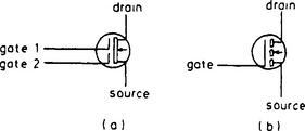
Figure I.8 Graphical symbols for (a) a dual-gate depletion-mode IGFET and (b) a single-gate enhancement-mode IGFET, both with n-channels
insulation-displacement connector A form of connector for terminating ribbon cables which clamps on the cable causing contacts in the connector to pierce the insulation of the cable to make connection with the conductors. It makes a quick and effective method of termination which avoids the need for soldering and cable stripping. A typical application for an insulation-displacement connector is for interconnecting printed-circuit or printed-wiring boards.
integrated circuit (IC) See hybrid integrated circuit or monolithic integrated circuit.
integrating amplifier An operational amplifier the output of which is equal to the time integral of the input waveform.
integrating circuit A circuit the output of which is approximately proportional to the time integral of the input signal. A common example is a circuit comprising a series resistor followed by a shunt capacitor as shown in Figure I.9. The time constant RC must be long compared with the period of the input pulses.

integrator Any circuit, network or transducer yielding an output waveform substantially similar to the time integral of the input waveform.
intelligent terminal A computer terminal which, in contrast with a dumb terminal, allows some local data processing and storage facilities. It may run an application which accesses the host in a more efficient or user-friendly manner. Often an intelligent terminal is a general-purpose microcomputer running terminal emulation software. See programmable workstation.
intensifier electrode An electrode used to increase the electron-beam velocity in a cathode ray tube after the beam has been deflected.
intensity modulation Variation of the density of an electron beam in accordance with the instantaneous value of the modulating signal. An obvious example of intensity modulation occurs in the reproduction of TV images by a picture tube in which the electron-beam density is controlled by the video signal so as to produce the variations of light intensity on the screen necessary to make up the picture.
interactive Responding instantly to signals from the user. Many computer applications, e.g. word processing, are interactive in that the user provides input to the system via the keyboard, mouse or other device and this affects the execution of the program. Conventional television and radio broadcasting, in contrast, are not interactive since the viewer or listener has no immediate control over the material being transmitted.
inter-carrier reception In a TV receiver a method of sound reception in which the FM sound signal is derived from the vision detector or a post-detector stage as an FM signal on a carrier frequency equal to the difference between the vision and sound carrier frequencies. The method has the advantage that the centre frequency of the sound signal is unaffected by drift of the local oscillator.
interface A boundary between two pieces of equipment with different functions or between systems in which data are expressed in different forms.
interference (1) In radio or TV reception any unwanted signal, natural or man-made, which adversely affects reception of the wanted signal.
Natural interference signals can arise from lightning flashes, and man-made interference from signals on nearby frequency channels or image channels, from electrical equipment and from car ignition systems.
Interference signals can be picked up on the receiving antenna or can reach the receiver via the supply mains. Some reduction in interference may be possible by using a directional antenna, by siting the antenna in an ‘electrically-quiet’ spot, or by the use of RF filters in the receiver mains supply. The best method is to prevent the radiation of interfering signals by fitting suppressors to the offending equipment. (2) In optics the effects observed when two sources of light of the same frequency are superimposed. Areas where the two waves are in phase are illuminated more brightly than those where the waves are in phase opposition and thus one of the most familiar effects is the formation of interference bands or rings.
interlaced scanning In TV a system in which the scanning agent, during each of its vertical sweeps, scans the image in a series of equidistantly-spaced lines, the lines of each sweep being slightly displaced vertically from those of the previous sweep, so that two or more sweeps are necessary to scan the whole of the picture area. In twin-interlaced scanning the lines of each vertical sweep fall midway between those of the previous sweep.
intermediate frequency (IF) In a superheterodyne receiver the carrier frequency to which the modulation of all received signals is transferred by the frequency changer. The signal from the frequency changer is accepted by the IF amplifier which is responsible for most of the gain and the selectivity of a superheterodyne receiver.
intermodulation Interaction between the components of two or more complex signals in a non-linear system leading to the production of new components with frequencies equal to the sums and differences of those of the components of the waves (combination frequencies).
intermodulation distortion Distortion arising from the non-linearity of the input-output characteristics of a system, equipment or component and resulting in the generation of new signals at combination frequencies of the two or more sinusoidal input signals. It is the generation of these new signals some of which are not harmonically related to the frequencies of the input signals which is responsible for the harsh sound of an overloaded audio amplifier.
Internet An autonomous global computer network originally set up in 1969 to allow academic and governmental bodies to exchange data. Interest in the Internet became fashionable in the early 1990s when it began to be used by a diversity of individuals and organisations for the exchange of scientific, cultural, religious, commercial and other information.
interpretation See computer language.
interrogator A combination of radio transmitter and receiver designed to radiate signals to a transponder and to display the response received.
interrupted continuous wave (ICW) Type of wave used for radio telegraphy in which an audio-frequency modulating wave or the audio-frequency modulated wave is keyed on and off.
interval In acoustics the difference in frequency or pitch between two sounds.
intrinsic diode Same as pin diode.
intrinsic semiconductor A semiconductor material in which the concentration of donor and acceptor impurities is equal so that there is no resultant excess of holes or electrons to act as charge carriers. Such material is known as i-type to distinguish it from n-type and p-type material.
inverse amplifier Same as inverter.
inverse feedback Same as negative feedback.
inverse impedances Two impedances the product of which is independent of frequency. Two simple examples of inverse impedances are a purely-inductive and a purely-capacitive impedance. The series and shunt elements in a constant-k filter are inverse impedances.
inverse networks Two two-terminal networks the impedance of which are inverse, i.e. their product is independent of frequency.
inverse voltage Of a diode in a rectifying circuit, the voltage appearing across the diode when it is non-conductive. See peak inverse voltage.
inverter (1) Equipment for converting DC into AC. (2) In logic circuitry an amplifier the output of which is equal in amplitude but opposite in polarity to the input signal. Such an amplifier can be used as a negator to convert a logic-1 signal to a logic-0 and vice versa.
ion A charged particle formed from an atom or a molecule by the loss or gain of valence electrons. If electrons have been lost, the resultant ion has a positive charge and if electrons have been gained, the ion has a negative charge. As matter is normally uncharged, ions are formed in pairs, one with a positive and the other with a negative charge. In gases the negatively-charged ions may be electrons and the positively-charged ions comprise the remaining parts of the atom or molecule where most of the mass resides.
ion burn An area of reduced luminosity on the screen of a cathode ray tube caused by partial destruction of the phosphor by bombardment by heavy negative ions which are liberated from the cathode or are formed by ionisation of the residual gas. The area is usually at the centre of the screen because the heavy ions are not deflected to the same extent as electrons by the deflecting fields. See aluminised screen, ion trap.
ion gun A device similar to an electron gun but in which the charged particles are ions.
ion implantation In semiconductor-device manufacture a technique whereby a required amount of an impurity can be introduced into the semiconductor material by bombarding it with ions of the impurity (usually boron or phosphorus). The ions can be released by an RF discharge or by use of a heated filament and are focused and accelerated by electrostatic means, using voltages up to 500 kV. The process has the advantage over diffusion of giving more precise control over the concentration and depth of penetration of the impurity.
ionisation The splitting of electrically-neutral matter into positively-charged and negatively-charged ions. Electronics is particularly concerned with ionisation of gases and there are a number of ways in which this can be achieved. For example the gas can be subjected to radiation such as ultra-violet light, X-rays or gamma rays. This occurs in the upper atmosphere where air is ionised by ultra-violet radiation from the sun to form the ionosphere.
A second method is ionisation by collision: if a voltage is applied between two cold electrodes in a gas tube the few positive and negative ions formed by ultra-violet light are collected at the electrodes. If the voltage is increased sufficiently all such ions will be collected but, in moving rapidly to the electrodes, some ions and electrons collide with gas atoms and split them into further ions. These, too, may liberate ion-pairs and the process results in a rapid build-up of ions. The presence of an electron stream from a heated cathode greatly assists ionisation by collision.
ionisation voltage The minimum voltage applied to a gas-filled tube which will cause ionisation. The ionisation voltage depends on the gas: for example for mercury vapour it is 10.4 V and for helium 24.5 V.
ion trap Method of avoiding ion burn of the screen of a cathode ray tube. In one method the electron gun is aimed at the neck of the tube and an external permanent magnet is used to deflect the electron beam to the axis of the tube. Heavy negative ions liberated from the cathode or by ionisation of the residual gas which are responsible for ion burn are deflected to a smaller extent than the electrons and continue to bombard the tube neck. The use of an aluminised screen has now rendered the use of ion traps unnecessary.
isolate (1) To disconnect equipment completely from all sources of power. (2) To provide a degree of physical protection by making an object or circuit inaccessible unless special measures are taken. (3) To use a buffer stage to prevent interaction between stages in electronic equipment.
isotropic Having the same properties in all directions. See also anisotropic.
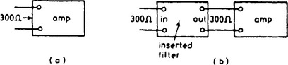
iterative impedance That value of impedance which, if used to terminate a network, gives an input impedance of the same value. The virtue of this concept is that networks used on an iterative-impedance basis can be inserted into circuits without affecting impedance levels. For example if the input impedance of an amplifier is 300 Ω (Figure I.10(a)) and if a filter with an iterative impedance of 300 Ω is inserted before the amplifier the input to the filter is also 300 Ω as shown in Figure I.10(b).