T
tachogenerator A generator mechanically coupled to a rotating shaft to give an electrical output proportional to the rotational speed of the shaft. This output may be used to indicate the shaft speed or may form an input to a speed-regulator circuit.
Tagged Image File Format (TIFF) A bitmap file standard widely used for storing images and transferring them, especially between computers of different types. A very versatile format, it can handle images having up to 32 bits per pixel and various compression algorithms. It is, perhaps, the closest approach to an industry-standard bitmap file format.
tandem connection Same as cascade.
tank circuit In general an oscillatory circuit. In particular a parallel LC circuit forming the load of a tuned amplifier (e.g. in a transmitter) or forming the frequency-determining element of an oscillator.
tantalum bead capacitor A type of polarised capacitor offering high capacitance with low losses and leakage in a compact package.
tape streamer A device for recording data at high speed on tape in a data cartridge. The most common use for tape streamers is for backing up hard disk drives, but they are also used for distributing large collections of software.
target The electrode in an electron tube on which the electron beam is focused. Thus the target of a cathode ray tube or a picture tube is the luminescent screen. In a simple camera tube such as an iconoscope, orthicon or vidicon the target is photosensitive and an optical image of the scene to be televised is focused on it. As a result the target develops a charge image which is discharged by the scanning beam to generate the tube output.
In camera tubes with an image section the target is of secondary-electron emitting material and the charge image is generated by bombardment of the target by photo electrons from the photo-cathode.
target language (US) Same as object code.
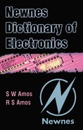
T bistable A bistable circuit with an input such that every time the input takes on its 1-state the output of the bistable goes to the complementary state. When the T input takes up its 0-state it has no effect on the output.
tearing In TV, erratic breaking up of part of a reproduced image by lateral displacement of some of the scanning lines caused by faulty line synchronisation.
tecnetron An early form of field-effect transistor pioneered by the French.
telecommunication The process of sending information from one point to another by electromagnetic means. The information can be of any kind, e.g. sound or picture signals, and the link between the two points may also be of any kind, e.g. by wire, radio, optical means or a combination of any of them.
telegraphy A system of telecommunication for the transmission of information consisting of graphic symbols, usually letters and figures, by use of a signal code. The system is used primarily where permanent records are required of the messages sent. The link may be of any kind, e.g. line or radio, and the code is often that used by teleprinters.
telemetry A system of telecommunication for the transmission of information on measurements, e.g. the water level in a reservoir is represented by an electrical signal suitable for transmission over the link which may be a line or radio or a mixture or both.
telephony A system of telecommunication for the transmission of speech or other audio signals. The link may be by line or radio or a mixture of both and is normally such as to provide two-way speech communication.
telepresence A computer technique similar to virtual reality in that the user dons a body suit or headset and gloves to provide an input. In telepresence, however, there is no virtual world. The computer controls a robot which mimics the user’s actions. Telepresence has applications in industry, exploration and military operations where some task must be performed in a hazardous environment. The robot enters the hazardous area and takes the risks, while the human operator remains safe.
teleprinter A machine capable of converting a written message containing letters and figures into a coded form suitable for transmission over a telegraph link to a similar machine which recreates the original message. The teleprinter has a keyboard similar to that of a typewriter and messages typed on it appear on a paper roll at the transmitting and receiving machines so that there are identical records of the message at both ends of the link.
teletext In TV a system of transmitting information in the form of letters, figures and simple diagrams, by signals incorporated in the television waveform. The information can be displayed on the screen of a suitably-equipped television receiver in place of or superimposed on the normal programme.
In this service, termed Ceefax by the BBC and Oracle by the IBA, the teletext information is transmitted as a pulse-coded signal occupying one of the normally-empty forward scanning-line periods in the field blanking interval. Several hundred different pages of teletext information can be transmitted using this system giving, for example, details of news items, weather reports, sports results etc. A receiver equipped with a teletext decoder enables the user to select any desired page.
teletypewriter (US) Same as teleprinter.
television The process of creating instantaneously at a distance a black-and-white or coloured image of a real or recorded scene and the movement occurring in it by means of an electrical system of communication. The term recorded scene includes pictures from cinema film, videotape, videodisc or transparency.
television camera Equipment containing the optical and electronic components required to generate a picture signal from the optical image of a scene. In a black-and-white camera the principal components are an optical lens system and a camera tube. The camera tube requires facilities for deflecting and focusing the electron beam and the camera may include a head amplifier for the camera tube output. A colour television camera incorporates at least three camera tubes and an optical device for splitting the optical image into its red, green and blue components. In addition some colour cameras have a fourth camera tube to generate the luminance signal.
Most television cameras include a viewfinder which may be optical or may be a picture tube fed from the camera output.
television camera tube See camera tube.
television system The particular combination of television signal waveform, method of transmitting vision and sound, channel width, channel spacing etc. chosen. There are a number of different systems and they have been classified by the CCIR. The system used in the United Kingdom is system I.
television waveform See video signal.
temperature coefficient In general a factor expressing the degree to which a quantity is affected by changes in temperature. More specifically it is equal to the relative change in the quantity per degree Celsius. Some electronic components are marked with their temperature coefficient. For example a capacitor marked N750 has a temperature coefficient of capacitance of −750 parts in 106.
temporary storage In computers storage reserved for intermediate results.
terminal A point where a signal is applied to or withdrawn from a network circuit or equipment. It is also known as an external node. See also computer terminal.
termination The external impedance connected to the two terminals of a transmission line. If this impedance is equal to the characteristic impedance of the line, the termination is described as matched and the wave is not reflected at the termination. For any other value of termination there is a reflected wave.
testing The carrying out of operations on a component, equipment or system to determine if it is functioning correctly or, for a new component etc, to determine if it is likely to function correctly when put into service. There are a number of different types of test. See accelerated life test, acceptance test, life test, maintenance test.
tetrode An electron tube with two grids between cathode and anode, that nearest the cathode being the control grid and the other carrying a fixed positive bias. There are two main types of tetrode:
(a) The screen-grid tetrode in which the positively-biased grid is designed as an electrostatic screen between control grid and anode virtually eliminating the grid-anode capacitance and so enabling the tube to be used as a stable RF amplifier. The Ia–Va characteristic contains the tetrode kink but if the tube is used only as a small-signal amplifier this is not a serious disadvantage.
(b) The kinkless tetrode in which the positively-biased grid is used, not to eliminate anode-grid capacitance but to eliminate the tetrode kink in the Ia–Va characteristic. Thus the tube is capable of large output-voltage swings and is used in power output stages, e.g. in AF amplifiers. See beam tetrode, critical-space tetrode, screen-grid electron tube.
tetrode thyristor A thyristor with two gate terminals, one connected to the inner n-region (anode gate) and the other to the inner p-region (cathode gate) and which can be switched to the on-state and to the off-state by signals applied to one of these gates. It is sometimes known as a silicon controlled switch. The graphical symbol is given in Figure T.2.
tetrode transistor See insulated-gate field-effect transistor.
text Data consisting of printable characters such as alphanumerics and punctuation marks. Such data uses a code such as ASCII or EBCDIC.
text file A file representing a string of printable characters such as alphanumeric characters and punctuation marks, perhaps in ASCII format.
thermal breakdown See thermal runaway.
thermal noise Noise arising from the thermal agitation of the electrons in a conductor. Although in a conductor with no applied voltage, the number of electrons passing a given point in one direction equals the number passing it in the opposite direction when the measurement is made over an appreciable period, there are momentary surfeits or deficits of electrons and their variation with time constitutes thermal noise. The magnitude of the noise voltage Vn is given by
where
and Δf = bandwidth over which the noise is measured. Substituting the value for k and putting T = 290°K for normal room temperature we have
For example the voltage generated across a 2-kΩ resistor over a bandwidth of 5.5 MHz is 131 μV.
thermal relay A relay which depends for its operation on the heating effect of an electric current.
thermal resistance The difference in the temperature at two points divided by the power flow between them when thermal equilibrium has been established. It is thus the temperature difference per unit dissipation and can be measured in degrees C per watt. The concept is useful in the design of heat sinks which must have a minimum thermal resistance to be able to dissipate the power transmitted through them satisfactorily. The thermal resistance depends chiefly on the mass and the surface area of the heat sink.
thermal runaway Cumulative effect which occurs in semiconductors in which the heat generated in the device by the current through it increases the current, so raising the temperature further. This results in a rapid rise in device temperature which can damage or even destroy the device. Where there is danger of thermal runaway, transistor circuits are designed to stabilise the mean current, a process known as DC stabilisation or stabilisation of the operating point.
thermionic emission The emission of electrons from a heated conductor. At normal temperatures the free electrons in a conductor have a certain mobility but their energy is not normally sufficient to enable them to escape from the surface of the conductor. If, however, the conductor is heated the electron energy is increased and some can escape into the surrounding space. The more the conductor is heated the greater is the number of electrons which escape. Thus the electrons liberated from the cathode of an electron tube are released as a result of thermionic emission.
thermionic tube An electron tube containing an electrode, normally the cathode, which must be heated to release the electrons or ions necessary to give conduction through the tube. See gas-filled tube.
thermistor A resistor with a large negative temperature coefficient of resistance. The temperature-sensitive materials used in thermistors are oxides of manganese or nickel formed into rods and fired at high temperature. The resistance of a thermistor decreases with increase in temperature and thus with increase in the current through it. Its behaviour, therefore, is the opposite of that of most metallic conductors. Small thermistors are heated by passing the current directly through the temperature-sensitive element but there are also indirectly-heated types where the current is passed through a winding electrically-insulated from the element.
Thermistors are used for surge suppression, e.g. a directly-heated type may be connected in series with the tube heaters in a radio receiver so as to limit the surge of current when the circuit is switched on and the heaters are cold and therefore of low resistance. Thermistors are also used for temperature measurement.
thermocouple Junction of two different metals which, when heated, generates an EMF which depends on the temperature of the junction. Thermocouples are used for measuring radio-frequency currents (by their heating effect) and for measuring high temperatures.
thermo-electric effect The generation of an EMF at the junction of two dissimilar metals when the junction is heated. The effect is sometimes described as the Seeback effect. See also Peltier effect.
thermostat A switch which operates automatically at a predetermined temperature and which is used, in conjunction with a heating or cooling device, to maintain a constant temperature in an enclosure. The switch is often operated by a bimetallic strip. Such an arrangement is used at radio transmitters to maintain a constant temperature for the piezo-electric crystal which determines the carrier frequency.
Thevenin’s theorem If an impedance Z′ is connected between any two points of a linear network the current which flows in it is given by V/(Z + Z′), where V is the voltage and Z is the impedance measured between the points before Z’ was connected.
thick-film circuit A circuit in which resistors and their interconnections are formed on a substrate by applying special inks via a stencil screen or metal mask and firing them in a furnace. Resistance accuracy of ±15% can be achieved. Where necessary the resistors can be adjusted by abrasive trimming or by a laser beam to an accuracy of 0.1%. Discrete components (resistors, capacitors, inductors, transformers, semiconductor diodes and transistors) can be mounted on a thick-film circuit.
thin-film circuit A circuit in which components and their interconnections are formed on a substrate by evaporation or sputtering of resistive, conductive or dielectric material. The components can be resistors, capacitors or inductors and the substrate can be glass, alumina or silicon. Discrete components (resistors, capacitors, inductors, transformers, semiconductor diodes or transistors) can be mounted on a thin-film circuit.
third-generation computer See digital computer.
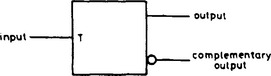
three-state output In logic circuitry a device output which in addition to the usual states representing the two logic levels has a third possible state (usually open-circuited) which has no logic significance. It is represented in diagrams as shown in Figure T.3. The importance of the open-circuit condition is that it enables an output to be effectively disconnected from its external circuit. Thus a number of outputs may be connected in parallel, e.g. on a bus without interference provided no more than one is enabled at a time.
threshold The minimum amplitude at which a signal will activate a device, e.g. in logic circuits, the minimum input voltage that will be recognised as a logic-1 rather than a logic-0.
threshold frequency See photoelectric-emission.
throat Of a horn-loaded loudspeaker that end of the horn where the cross section is a minimum.
thumbnail A reduced-size reproduction of a computer graphic. Some applications create illustrated catalogues of directories containing graphics files with a thumbnail of each for ease of identification and selection.
thyratron A hot-cathode gas-filled triode or tetrode in which the control grid initiates anode current but does not control it. Provided that the anode voltage is high enough a grid voltage exceeding a critical value initiates anode current which is then limited only by the HT supply voltage and the resistance of the external anode circuit. To cut off the anode current both anode and grid voltages must be below certain values.
Thyratrons were extensively used as electronic switches in control circuits, e.g. for controlling the power fed to a load from the mains. The thyratron was connected in series with the load and acted as a half-wave rectifier, the angle of conduction of which could be controlled by the bias applied to the control grid. Thyristors have now replaced thyratrons in most applications. The graphical symbol for a thyratron is given in Figure T.4.
thyristor A bistable semiconductor device which can be switched to the on-state (and in some types to the off-state also) by a signal applied to the gate terminal.
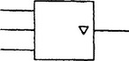
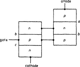
Thyristors are of four-layer pnpn construction and the outer layers are known as the anode and cathode as indicated in Figure T.5. If the anode is made positive with respect to the cathode, pn junctions a and c become forward-biased and therefore of low resistance but junction b is reverse-biased thus limiting the current through the device to the leakage current of this junction. If, however, the anode voltage is increased sufficiently avalanche breakdown occurs in the centre junction and a large current flows through the device, limited only by the voltage and resistance in the external circuit: this is the on-state. The anode voltage can now be reduced to a low value but the on-state will persist until the current through the device falls below a critical value when the device becomes non-conductive again (the off-state). If the anode is made negative with respect to the cathode, junction b becomes conductive but junctions a and c are reverse-biased and prevent significant current flow: for such voltages the device remains in the off-state. Such a device is known as a reverse-blocking
diode thyristor. Two such devices connected in reversed parallel form a bidirectional diode thyristor. A variant of the diode thyristor which remains in the on-state for negative anode voltages is known as a reverse-conducting diode thyristor.
By applying a signal to one of the inner layers the pnpn structure can be triggered into the on-state even at low anode voltages and again will remain in the on-state until the current has fallen below the critical value. The inner region is termed the gate as indicated in Figure T.6 and the three-terminal device is termed a reverse-blocking triode thyristor or, more simply, a thyristor.

The mechanism of the triggering process is best understood by reference to the two-transistor analogue of the thyristor. As shown in Figure T.7 a thyristor can be regarded as a combination of an npn and a pnp transistor with the collector of each connected to the base of the other (see multivibrator). Suppose such a device has a small positive anode voltage but is in the off-state. As explained, junctions a and c will be forward-biased and junction b reverse-biased: these are the normal conditions for the two constituent transistors to operate as amplifiers. When a positive voltage is applied between gate and cathode it increases the forward bias of the npn transistor with the result that current crosses junction c and this, by normal transistor action, gives rise to a collector current in the inner n-region which is also the base region of the pnp transistor. By normal amplifying action in the pnp transistor this gives rise to a collector current in the inner p-region which is also the base region of the npn transistor. In this way positive feedback occurs and, if the combined current gain of the two transistors exceeds unity the feedback is regenerative causing a very rapid build-up of current which puts the device into the on-state. The gate voltage can now be removed but the thyristor will remain conductive until the current in it falls below the critical value—behaviour typical of a bistable multivibrator. From the symmetry of the device structure it is clear that the thyristor could alternatively be triggered by a negative signal applied to the inner n-region. Thus there are two types of reverse-blocking triode thyristor one with a p-gate (cathode gate) and the other with an n-gate (anode gate).
There are corresponding reverse-conducting triode thyristors and a type which can be triggered into the off-state known as a turn-off thyristor. A very useful thyristor can be constructed of two triode thyristors in reverse parallel with a common gate connection: this is known as a triac and can be triggered into conduction by a positive or negative signal applied to the gate. If external connections are made to both inner layers of the pnpn structure the thyristor so obtained can be triggered into the on-state and into the off-state by appropriate signals applied to one of the two gates. This is a tetrode thyristor alternatively known as a silicon controlled switch which is used, amongst other applications, as a field oscillator in television receivers.
The chief application for thyristors is as rectifiers in mains-operated power-control systems where the conduction angle is controlled by signals applied to the gate. For this reason thyristors are often known as silicon controlled rectifiers.
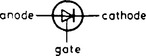
The general graphical symbol for a thyristor is given in Figure T.8. The symbols for individual types of thyristor are given in the particular definitions.
time base In cathode ray oscilloscopes that deflection of the electron beam which is defined with respect to time. Usually this is the horizontal deflection, the waveform to be displayed providing vertical deflection.
time-base generator Equipment for generating the signals providing the time base for an oscilloscope. For electrostatic deflection the time base generator must provide a sawtooth voltage and, for flexibility in the applications of the oscilloscope, a wide range of sawtooth frequencies is required.
time constant Of a quantity varying exponentially with time, the time taken for the quantity to vary by 63% (i.e. 1 − 1/e) of the full extent of the change. When a capacitor C charges from a DC supply via a resistor R the voltage across the capacitor reaches 63% of its final value after RC seconds, where R is in ohms and C in Farads. When the capacitor is discharged its voltage reaches 37% of its initial value in RC seconds as shown in Figure T.9. RC is thus the time constant of the circuit. If an inductor L is connected across a DC supply via a resistor R the current grows exponentially with time and reaches 63% of its final value (E/R) in L/R seconds where L is in Henries and R in ohms.

time division multiplex (TDM) A multiplex system in which each signal is allowed use of the communications path for a short time interval. Usually there are a number of signals and they use the path in turn.
time slot A recurrent interval of time which can be uniquely defined. For example a particular forward line-scanning period during the field blanking interval is the time slot occupied by the teletext signal.
timing The process of ensuring that all the signals necessary to make up a complex waveform or to carry out an operation arrive in the correct sequence and at the correct intervals.
T metal-oxide semiconductor transistor (TMOS) An insulated-gate field-effect transistor so constructed that the current flow is for the most part perpendicular to the plane of the layers as in planar bipolar transistors; the source consisting of a large number of sites each associated with a short channel, the parallel connection of which yields low switching times and low source-drain resistance in the on condition. Large source and drain areas permit the transistor to give substantial output power.
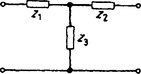
T-network A network consisting of two series elements with a shunt element connected to their junction. Figure T.10 illustrates a T-network: it may be regarded as an example of a star network with three branches.
toggle (US) Same as bistable circuit.
tone (1) In audio a sinusoidal signal of constant frequency used for test purposes or to identify circuits. (2) In popular speech the term is used to describe the quality of a musical sound. For example a cello may be described as having a mellow tone. (3) In photography and TV the degree of light or shade of an image or an element of an image.
tone control A circuit for adjusting the frequency response of an audio amplifier. The chief ways in which the response may be modified are indicated in Figure A.12 and high-quality equipment is usually capable of all such responses but in simple receivers with a single tone control this usually introduces top cut only.
tone wedge In TV a test image consisting of a series of areas of which the tone varies in steps between black and white. Most TV test cards incorporate a tone wedge which can be used for the adjustment of receivers.
top cut Attenuation distortion in which the upper frequencies of the audio range are attenuated.
top lift Accentuation in which the upper frequencies of the audio range are emphasised.
totem-pole output Same as single-ended push-pull.
touch sensor or switch A switch which operates when a finger comes into direct connection with two closely-spaced contacts or when the finger provides a capacitive link between the contacts. The direct-connection type of switch is fed from a DC supply and the presence of the finger causes a small direct voltage to be injected into a monostable or bistable circuit which performs the required switching action. The capacitive type of switch is fed from an AC supply and the presence of the finger on an insulating cover over the contacts causes a small alternating voltage to be injected into the following circuit which brings about the required switching action. Touch switches are extensively employed, e.g. in controlling lifts and in channel switching on television receivers.
trace Of a cathode ray tube the pattern generated on the screen by the movement of the electron beam.
track A channel containing stored data in a storage medium such as a tape or floppy disk or hard disk.
trackball or trackerball In computing a pointing device used as an alternative to a mouse. The trackerball is a fixed unit containing a captive ball whose uppermost portion is exposed. The user manipulates the ball with his thumb or the palm of his hand to guide the pointer around the screen. Trackerballs are also used in closed-circuit television systems, especially for security surveillance, to pan and tilt remotely mounted surveillance cameras.
tracking (1) In a superheterodyne receiver maintenance of the correct difference between signal frequency and oscillator frequency as the tuning is altered. When similar sections of a ganged tuning capacitor are used for signal-frequency and oscillator circuits, trimming and padding capacitors are included in the oscillator circuit to help maintain this frequency difference. In fact even with such aids the difference frequency can be made correct (i.e. equal to the intermediate frequency) only at three settings of the capacitor. These are therefore positioned one near each end of the tuning range and the third at the centre: this is known as three-point tracking.
(2) In record reproducing equipment the accuracy with which the plane of vibration of the reproducing stylus is maintained at right angles to the direction of the groove at the stylus point as the reproducing head moves across the disk. By offsetting the head on the arm (or curving the arm) and by arranging for the stylus to overshoot the disk centre to a critical extent the tracking error can be minimised.
(3) The formation of carbon conducting paths across the surface of insulating materials by electric stress. Certain insulating materials, notably those made of fibrous material such as paper and paxolin, are very subject to tracking.
transceiver A device, usually portable, which can be used as a transmitter or a receiver. Much of the circuitry of a transceiver is common to the transmitter and the receiver.
transconductance (US) Same as mutual conductance.
transducer A device which responds to an input signal in one form of energy and gives an output signal bearing a relationship to the input signal but in a different form of energy. The forms of energy are usually acoustic, mechanical and electrical. For example a microphone is a transducer which converts acoustic into electrical energy. This is an interesting example because there are, in fact, two energy conversions in a microphone. The original acoustic energy (oscillations of air) is first converted into mechanical energy (vibrations of a diaphragm) which is then converted into electrical energy (changes in voltage) at the output terminals.
transductor A ferromagnetic device in which the degree of saturation of the core (and hence the effective inductance) can be controlled by the current flowing in one of the windings. It is sometimes known as a saturable reactor.
transfer characteristic (1) Of an active device, the curve obtained by plotting the output current against the input voltage or current. For an electron tube or field-effect transistor the input is taken as a voltage and for a bipolar transistor as a current. (2) Of a camera tube, the curve obtained by plotting the output current against the light input. (3) Of a magnetic recording system, the curve obtained by plotting the magnetic flux density against the magnetising force.
transfer coefficient (or constant) Same as image transfer coefficient.
transfer impedance Between any two pairs of terminals in a network, the complex ratio of the voltage applied to one pair to the resultant current at the other pair, all other terminals being terminated in a specified manner, e.g. if there are other generators these should be replaced by their internal impedances. The term is defined in the same manner as mutual impedance but the terminating conditions differ.
transformer A device consisting of two or more inductively-coupled windings. Transformers are widely used in electronics and the following are typical applications:
(a) For changing the voltage of an alternating supply. Where equipment requires a supply voltage which differs from that of the mains, a transformer can be used to give a suitable alternating voltage and at the low mains frequency a laminated ferromagnetic core can be used.
(b) For isolation. Where it is undesirable to have physical connection to the mains, a 1:1 transformer can be used to supply the power. Such transformers are often used with musical instruments such as electric guitars.
(c) For impedance matching. When the impedance of a load is necessarily different from the optimum value required by the generator, a matching transformer can be included between the two impedances to achieve maximum power transfer. If the impedance ratio is n:1 the transformer turns ratio should be √n:1.
(d) For coupling. Step-up transformers are used between stages in electron-tube amplifiers to give voltage gain and step-down transformers between bipolar-transistor stages to give current gain. At low frequencies such transformers use laminated ferromagnetic cores but at radio frequencies ferrite cores or even air cores can be used. In RF transformers one or both of the windings may be tuned (and the degree of coupling adjusted) to give the required passband. In oscillators a transformer may be used to provide coupling between input and output circuits of an active device so providing the positive feedback essential for oscillation.
(e) To convert between balanced and unbalanced operation. Transformers with centre-tapped windings are used extensively in circuits where balanced operation is required e.g. in push-pull amplifiers, ring modulators.
Where there is no objection to a physical connection between primary and secondary circuits, a transformer need have only one winding with tapping points, the primary or secondary circuit being connected between suitable tapping points. This is known as an autotransformer and line output transformers in television receivers often have a number of tapping points to feed the scanning coils and the various auxiliary circuits which rely on the line output stage for their power.
The graphical symbols for (a) an air-cored transformer and (b) an autotransformer with a ferromagnetic core are shown in Figure T.11.
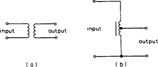
Figure T.11 The graphical symbol for (a) air-cored transformer and (b) an auto-transformer with a ferromagnetic core
transient In an acoustic or electrical system, the signal which persists for a brief period following a sudden disturbance to the steady-state conditions. Transients have an irregular and non-repetitive waveform. The term is applied particularly to the damped oscillations which follow shock excitation of a resonant system.
transient response The ability of a circuit or device to reproduce transients without distortion.
transistor A semiconductor device of which the output current can be controlled by the signal(s) applied to one or more input terminals. See bipolar transistor, field-effect transistor.
transistor-transistor logic (TTL) A system in which use is made of logic elements comprising chiefly bipolar transistors. In one TTL circuit the output stage is single-ended push-pull in which one transistor is conductive at a time. Speed of operation is high but is limited by the fact that the bipolar transistors are driven into saturation and, because of carrier storage, switch off more slowly than they switch on. This limitation has been overcome in a recent modification to the TT system in which Schottky diodes are connected between the collector and the base of the transistors to prevent them from saturating. This has resulted in a significant improvement in speed of operation.
transit angle The transit time expressed as an angle. Transit angle is thus the product of the transit time and the angular frequency.
transition In a waveform an instantaneous change from one value of amplitude to another. An ideal pulse thus contains two transitions. The term ‘edge’ is sometimes used instead, e.g. the trailing edge of a pulse.
transition frequency (1) Of a bipolar transistor the frequency (fT) at which the modulus of the common-emitter current amplification factor has fallen to unity. It thus measures the highest frequency at which the transistor can be used as an amplifier; it is, in fact, the gain-bandwidth product for the transistor. (2) See turnover frequency.
transitron A pentode in which use is made of the virtual cathode set up between the screen grid and the negatively-charged suppressor grid. The virtual cathode, suppressor grid and anode can be treated as electrodes of a triode, the real cathode, control grid and screen grid being the electrodes of a second triode. Thus the pentode can be used as the equivalent of some two-triode circuits notably multivibrators. The equivalent of a monostable multivibrator is known as a phantastron.
The negative-resistance characteristic between suppressor grid and screen grid which gives the circuit its name can be used as the basis of an oscillator.
transitron oscillator An oscillator which utilises the negative-resistance kink in the screen-grid characteristic of a pentode with a negatively-biased suppressor grid. See dynatron oscillator, transitron.
transit time In general the time taken for a charge carrier to cross a given gap. In electron tubes the time taken by electrons to travel from the cathode to other electrodes is of great importance and, in fact, limits the upper frequency at which the tubes can be used successfully. Thus tubes for high-frequency applications are constructed with very small inter-electrode spacings to minimise transit time. See disk-seal tube. On the other hand microwave tubes such as travelling-wave tubes make use of transit time in their operation.
transmission line A system of conductors connecting one point to another along which electric or electromagnetic energy can be sent. Thus telephone lines and power-distribution lines are examples of transmission lines but in electronics the term usually implies a line used for the transmission of RF energy, e.g. from a radio transmitter to the antenna.
An essential feature of such a transmission line is that it should guide energy from the sending end to the receiving end without loss by radiation. One form of construction commonly used consists of two similar conductors mounted close together but maintained at a constant separation. These two conductors form the two sides of a balanced circuit and any radiation from one of them is neutralised by that from the other. Such twin-wire lines are used for carrying high RF power, e.g. at transmitters.
For low-power use the coaxial form of construction is often employed, one conductor being in the form of a cylinder which surrounds the other at its centre and thus acts as a screen. Cables so constructed are extensively used to couple FM and television receivers to their antennas.
At frequencies above approximately 1000 MHz transmission lines are usually in the form of waveguides which may be regarded as coaxial lines without the centre conductor, the energy being launched into the guide or abstracted from it by probes or loops projecting into the guide. See characteristic impedance, coaxial cable.
transmitter In general a device which sends a signal. A telephone transmitter converts sound waves to a.f. signals for transmission over telephone circuits. A radio transmitter sends electromagnetic waves conveying sound or television programmes or other forms of data.
transparent In computing and telecommunications a term used to describe a vital process which occurs automatically and without affecting the user; ideally the user should be unaware that it is happening. An example is the handing over of a mobile user from one base station to another in cellular radio.
transponder A combination of radio receiver and transmitter designed to radiate an acknowledging signal automatically when a correct interrogating signal is received.
transputer A combination of microcomputer-type devices designed to achieve higher operating speeds than a conventional microprocessor.
In a normal microprocessor the various operations needed to obtain the desired end result are carried out sequentially as the program indicates. However, in the transputer a higher operating speed is achieved by sharing the operations between a number of microprocessors which operate simultaneously. This parallel mode of working is not easy to achieve technically. Moreover conventional computer languages cannot be used and a new language OCCAM has been designed for use with the transputer.
transverse magnetisation In magnetic recording, magnetisation of the tape across its width, i.e. at an angle to the direction of tape movement. This method is used in video tape recorders as a means of achieving the high tape-to-head speed necessary to record the high video frequencies whilst still keeping a low speed of tape movement. The high transverse scanning speed is achieved by using a number of heads around the circumference of a drum which rotates so sweeping the heads across the tape.
trapezium distortion Same as keystone distortion.
trapezium modulation A system of amplitude modulation used at sound broadcast transmitters to permit a higher average modulation depth and so give improved intelligibility in areas of low field strength. To achieve this result the AF signal is clipped at an adjustable amplitude level and passed through a low-pass filter to suppress the harmonics introduced by the clipper. Thus peak signals become trapezoidal in waveform.
trap valve amplifier Amplifier with a number of outputs with a high degree of isolation between them used for distributing a broadcast programme to a number of destinations.
travelling-wave tube (TWT) An electron tube used at VHF and UHF in which the input wave travels along a slow-wave structure so that its axial velocity equals that of an electron beam fired along the axis, the resulting velocity modulation and consequent bunching providing the required amplification.
As shown in Figure T.12(a) the tube contains an electron gun at one end and a collector at the other, the intervening space being occupied by a helix or other form of slow-wave structure. The input signal is fed into one end of the slow-wave structure and the amplified output is abstracted from the other. The slow-wave structure is designed to reduce the velocity of electromagnetic waves which thread the structure so that the axial velocity is equal to that of the electron beam. Interaction between the wave and electron beam produces amplification. For a helix the factor by which the wave velocity is reduced is the ratio of the circumference to the pitch. Travelling-wave tubes are extensively used as microwave amplifiers and can be designed to have very wide bandwidths. The graphical symbol for one type of travelling-wave is shown in Figure T.12(b).

Figure T.12 (a) Simplified construction of a travelling-wave tube and (b) graphical symbol for an O-type travelling-wave tube with indirectly-heated cathode, intensity-modulating electrode, focusing electrode, slow-wave structure with connection, collector, focusing coil and window couplers to input and output waveguides
triac See bidirectional thyristor, thyristor.
trigatron Same as trigger tube.
trigger circuit A two-state circuit which can switch from one state to the other automatically or by external signals. See astable circuit, bistable circuit, multivibrator.
triggering The initiation of a change of state in a device by means of an external signal. The significant feature of triggering action is that the change of state continues automatically and independently of the external signal once it has been started. See bistable circuit, monostable circuit.
trigger tube A gas-filled tube containing a spark gap in which the main discharge can be initiated or terminated by a signal applied to an auxiliary electrode. If the external signal causes conduction in the tube, the state of conduction persists after the triggering signal has ceased. The graphical symbol for a trigger tube is given in Figure T.13.
trimming In general the process of fine adjustment of a variable resistor, capacitor or inductor. In particular a trimming capacitor is a small preset component connected in parallel with each section of a ganged tuning capacitor and which is adjusted to compensate for small differences in capacitance between the sections or to achieve three-point tracking in superheterodyne receivers.
trinitron A precision-in-line television picture tube pioneered by the Japanese.
triode An electron tube with three electrodes namely a cathode, control grid and anode. This was the first amplifying tube and was invented by Lee de Forest in 1905 when he inserted a grid in a diode. By suitably biasing the grid with respect to the cathode it is possible to control the density of the electron stream from the cathode which reaches the anode. Thus the grid voltage controls the anode current and by including a load in the anode circuit, the anode voltage becomes an amplified copy of the signal applied to the control grid. For linear amplification the grid must be suitably biased.
Such tubes have been widely used in electronic equipment since their invention, their use being confined to audio and subaudio frequencies. The internal anode-to-control grid capacitance makes triodes unsuitable for RF amplification. The graphical symbol for an indirectly-heated triode is given in Figure T.14. For most applications triodes have now been superseded by transistors.
triple detection See double superheterodyne reception.
tri-state output Same as three-state output.
trochotron A multi-electrode tube used for counting. It has a single cathode surrounded by a number of target electrodes and a magnetic field is employed to ensure that the electron beam moves around the cathode to strike the targets in sequence.
tropicalising The practice of encapsulating whole equipments or circuit boards in materials designed to survive harsh environments, such as high humidity, temperature extremes or the presence of corrosive chemicals.
true colour Colour stored digitally as 24 bits per pixel, that is 8 bits to represent the levels of each of the red, green and blue primaries. This gives a palette of 224 = 16,777,216 colours, more than the human eye can distinguish. See colour model.
truth table For a logic function a table showing all the possible combinations of input signals and, for each, the output signal. As a simple example the following is the truth table for an AND function showing that a logic-1 output is obtained only when both inputs stand at the 1-state.
| input 1 | input 2 | output |
| 0 | 0 | 0 |
| 0 | 1 | 0 |
| 1 | 0 | 0 |
| 1 | 1 | 1 |
If the logic convention is reversed so that logic-1 becomes logic-0 and vice versa the truth table takes the form shown below
| input 1 | input 2 | output |
| 1 | 1 | 1 |
| 1 | 0 | 1 |
| 0 | 1 | 1 |
| 0 | 0 | 0 |
which shows that a logic-1 output is obtained when either input is at logic 1. This is the truth table for an OR gate and it shows that whether a given gate acts as an AND gate or an OR gate depends on the logic convention adopted.
tuned circuit A resonant circuit of which the resonance frequency has been adjusted to the desired value.
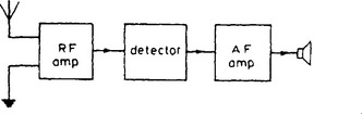
tuned radio-frequency receiver (TRF) A radio receiver incorporating one or more stages of radio-frequency amplification before the detector and one or more audio-frequency stages after it. A block diagram of a TRF receiver is given in Figure T.15. Such receivers were used in the 1920s but the number of tuned circuits it was possible to include in them was limited by the difficulty of ganging the tuning controls. The selectivity was therefore poor and TRF receivers were superseded by superheterodyne types in the early 1930s.
tuner (1) Short for tuning capacitor. (2) A radio or television receiver containing little or no amplification after the detector and no internal means of monitoring reception. It is normally used in conjunction with an external amplifier, monitor or tape recorder, e.g. in a hi-fi system.
tuning (1) Of a tuned circuit the process of adjusting the resonance frequency to a desired value. For an LC circuit this can be done by adjusting the capacitance, the inductance or both. (2) Of a receiver the process of adjusting it to respond to a wanted signal.
tuning capacitor A variable capacitor forming part of a tuned circuit and used to adjust the resonant frequency.
tuning indicator Of a receiver a device giving visual indication of correct tuning. A number of devices are in common use. The correct tuning point may be indicated by a simple meter movement, by the area of luminescence on the screen of a small cathode ray tube or, for TV receivers, by the width of a line of luminescence on the screen.
tunnel diode A pn diode which makes use of the tunnel effect. The forward characteristic of a tunnel diode exhibits a region of negative resistance as shown in Figure T.16 (a) which can be exploited in an oscillator, an electronic switch or for low-noise amplification at frequencies up to 1000 MHz. The graphical symbol for a tunnel diode is shown in Figure T.16 (b).
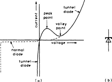
Figure T.16 (a) Characteristics for a tunnel diode (solid) and a normal diode (dashed) and (b) graphical symbol for a tunnel diode
tunnel effect Penetration of the potential barrier at the junction between highly-doped p- and n-regions by electrons which have insufficient energy to surmount the barrier. This effect is impossible to explain in terms of classical physics but is in agreement with quantum mechanics. Because of the tunnel effect the forward characteristics of a tunnel diode differs from that of a normal pn diode. For example current begins to flow across the junction at a very low value of forward bias and it increases with increase in bias up to a maximum (known as the peak point) at about 0.1 V for a germanium diode and then falls reaching a minimum (known as the valley point) at about 0.3 V where the characteristic joins that for a normal pn diode as shown in Figure T.16 (a). Thus the tunnel effect gives the characteristic a region of negative slope between the peak and valley points. The reverse characteristic for a tunnel diode also differs from that of a normal pn diode in that breakdown occurs almost at zero bias as for a backward diode.
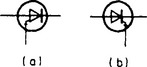
turn-off thyristor A thyristor which can be switched from the on-state to the off-state by a signal applied to the gate. n-gate and p-gate types exist and their graphical symbols are given in Figure T.17.
turnover frequency (US) In disk recording the frequency at which the recording characteristic changes from a constant-amplitude to constant-velocity type.
tweeter A small loudspeaker unit designed to operate at audio frequencies above approximately 2 kHz. Tweeters are often piezo-electric types and are used in combination with other units and crossover networks in high-quality wide-range loudspeakers.
twin-interlaced scanning See interlaced scanning.
twin-T network Same as parallel-T network.
twisted pair A cable consisting of two individually insulated wires twisted tightly together. The twisting brings the two conductors in close proximity so that they respond equally to any interfering fields. The induced voltages therefore cancel, minimising the effects of the interference.
two-quadrant multiplier A multiplier the operation of which is restricted to one sign only of the input signals.
two-terminal-pair network A network of which the characteristics are specified at four particular terminals, two acting as input and the other two as output. The network may have other terminals. Alternatively known as a two-port network.