
66 Optical Coding Theory with Prime
star
coupler
1
star
coupler
2
station
1
station
2
station
1
station
2
:
:
:
:
:
:
:
:
:
:
:
:
:
:
:
:
:
:
:
:
:
:
star
coupler
L
station
M
station
M
:
:
:
:
:
:
t
t
optical
pulse
t
t
to star coupler 1
to star coupler 2
to star coupler L
2-D spatial-
temporal code
delay-lines
encoder
transmitters
receivers
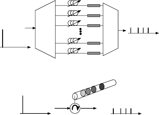
FIGURE 2.12 Spatial-temporal amplitude coding in multiple fibers and star couplers.
(Source: Reproduced with permission from Guu-Chang Yang andWingC.Kwong,Prime
Codes with Applications to CDMA Optical and Wireless Networks,Norwood,MA:Artech
House, Inc., 2002.
c
! 2002 by Artech House, Inc.)
Figure 2.12 shows an example of spatial-temporal-amplitude-coding systems with
multiple optical fibers and star couplers [22, 23]. Assume that there are M stations
and each of them is assigned a 2-D binary (0,1) codeword of size L ×N as its address
signature, where L is the number of spatial channels (provided by optical fibers and
star couplers, in this example) and N is the number of time slots [33, 53]. A narrow
optical pulse, which represents the transmission of a data bit 1, is first split into L
pulses; each pulse is time-delayed to one of the N time slots, according to the address
codeword of the intended receiver. T hese L pulses are then conveyed separately via
their own optical fibers and multiplexed with the corresponding pulses from other
stations at the star couplers. The decoders in the receivers reverse the process to give
correlation functions.
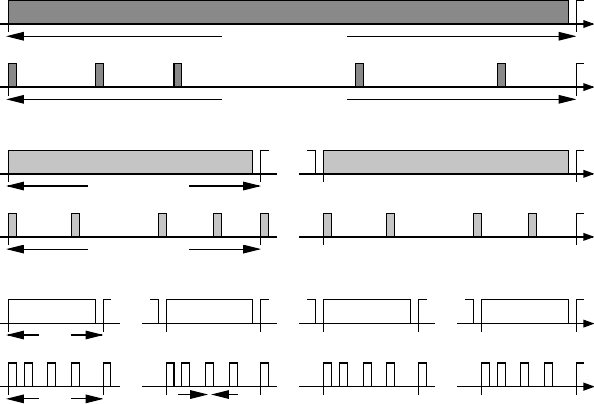
Figure 2.13 illustrates an example of encoding and decoding processes of 2-D
binary pixels in spatial-temporal amplitude coding [24, 26]. With the support of 2-
Dbinary(0,1) codes [33, 53], the tech n ique is suitable fo r parallel transmission
and simultaneous access of multiple d igitized 2- D images. T here is no need to per-
form the bottleneck-prone parallel-to-serial or serial-to-parallel conversion because
the pixels of every digitized image are transmitted in parallel. The concept also ap-
plies to free-space optics, in lieu of the multicore fiber or fiber bundle [25]. In this

Optical Coding Schemes 67
optical
MUX
:
:
:
:
:
:
:
:
:
:
:
:
optical
DEMUX
1
4
4
0
4
1
1
0
2-D
unipolar
code
2-D address
code
encoded
pixels
multiplexed
pixels
1
1
1
0
2-D
correlation
functions
encoder 1
2-D images
recovered
2-D
images
encoder M
encoder 2
:
:
decoder 1
decoder M
decoder 2
multicore fiber
or optical-fiber
bundle
FIGURE 2.13 Example of the encoding and decoding processes of 2-D binary pixels in
spatial-temporal amplitude coding, where black squares represent dark pixels and the number
in each square of the 2-D correlation functions represents the darkness level after correlation.
example, 2-D images of 2 ×2binarypixelsaretransmitted,andeachblackpixel
is encoded at an optical encoder with a 4 ×42-Dunipolarcodeword,formingan
array of 8 ×8codedpixels.Theseencodedpixelsarethenmultiplexedwith the cor-
responding encoded pixels from other stations at an optical MUX. Afterward, the
multiplexed arrays of 8 ×8encodedpixelsaretransmittedinparallelviamulticore
fiber, optical-fiber bundle, or free space, and later distributed to all stations by an
optical DEMUX. If an array of coded pixels arrives at the correct decoder, an auto-
correlation function, wh ich is represented by a high (darkness-level) number, r esults.
Otherwise, a cross-correlation function, which is represented by a low number, re-
sults and is treated as interference. By threshold-detecting the darkness levels, the
binary pixels of the transmitted 2-D image are recovered.
68 Optical Coding Theory with Prime
2.6 2-D SPECTRAL-TEMPORAL AMPLITUDE CODING
If d eployment of multicore fiber or optical-fiber bundle is notpossibleortoocompli-
cated, one altern ative is to use a hybrid WDM-coding scheme [33, 54, 55], in which
1-D time-spreading codewords are used in conjunction with multiple wavelengths.
Every codeword is reusable and can be sent out simultaneouslyatdifferentwave-
lengths, if needed. The selection of codewords of a specific wavelength at a receiver
is done by an optical WDM filter placed in front of the optical decod er. The code
length and, in turn, the speed of hardware are reduced due to the lessening in the
number of simultaneous users in each wavelength. However, unless there is a cen-
tral controller coordinating the wavelength usage among simultaneous users, wave-
lengths cannot usually be utilized evenly, and the scheme fails to achieve the optimal
performance, as discussed in Section 5.1 [33, 55].
Another approach, spectral-tempor al amplitude (or wavelength-time) coding,
imbeds multiple wavelengths within 1-D time-spreading codewords as the sec-
ond coding dimension [14, 28–30, 33, 34, 36, 37, 55–61]. The scheme involves fast
wavelength hopping, and the wavelength-hop takes place at every pulse of a time-
spreading codeword, instead of having the same wavelength for all pulses within
each codeword as in the afor em entioned hybrid WDM-coding scheme. Using the
same number of wavelengths and code length, 2-D wavelength-time codes, such as
the prime codes in Chapter 5, have a larger cardinality than and can perform as well
as the 1-D time-spreading codes used in the hybrid WDM-codingscheme.
WDM
DEMUX
WDM
MUX
t
t
t
narrow,
broadband
optical pulse
intensity
modulators
optical
circulator
λ
1
λ
2
λ
3
λ
L
-
1
λ
L
tunable
delay-lines
FBGs
wavelength-
time code
wavelength-
time code
(a)
(b)
λ
1
-λ
L
λ
1
-λ
L
λ
1
λ
4
λ
3
λ
6
λ
1
λ
4
λ
3
λ
6
t
λ
1
λ
4
λ
3
λ
6
FIGURE 2.14 Spectral-temporal-amplitude encoders in (a) waveguide and(b)fiber[34,36,
78, 81, 82].
Optical Coding Schemes 69
Figure 2.14(a) shows a waveguide-based, spectral-temporal-amplitude encoder,
which consists of WDM MUX/DEMUX devices, such as thin-film filters, arrayed-
waveguide-grating (AWG) devices, holographic Bragg reflectors, and micro-disk
resonators [3 0, 34, 36, 37, 77 , 85, 86], combined with tunabletime-delayelements.
Anarrow,broadbandlaserpulse,whichrepresentsthetransmission of a data bit 1,
is split into L pulses of distinct wavelengths, where L is the number of wavelengths
used in the wavelength-time codes. These multiwavelength pulses are time-delayed
by tunable delay-lines, according to the address codeword oftheintendedreceiver.If
awavelengthisnotusedinthecodeword,itwillbeblockedbyan intensity mo dula-
tor along that wavelength path. This encoder is integrable byfabricatingthecompo-
nents all in the waveguide. The all-fiber approach in Figure 2.14(b) places segments
of fiber Bragg gratings (FBGs) with different center wavelengths inside a piece of
optical fiber. The locations of these wavelength segments, which are usually not tun-
able, determine the spacings of the corresponding wavelength pulses [78–82]. More
examples on AWG- and FBG-based encoder/decoder designs thataretunableare
given in Section 2.10.
2.7 THREE-DIMENSIONAL CODING
To further improve the number of simultaneous users and subscribers, higher coding
dimension can be achieved by combining temporal, spatial, and spectral coding [32,
63]. Furthermore, the use of the two polarizations of opticalfieldtoreplacetheuse
of multiple fibers in the spatial domain has been proposed [31]. 3-D unipolar codes
are needed to support this kind of coding schemes. The prime codes that support 3-D
coding are studied in Chapter 8 [33].
2.8 MULTIRATE AND MULTIPLE-QoS CODING
So far in this chapter, only one type of service with identicalbitrateisassumedto
exist in coding-based optical systems and networks. However, future systems are ex-
pected to support a variety of services, such as data, voice, and video, with different
bit rates, QoSs, and even priorities. It is known that coherent (phase) coding schemes
have better performance than incoherent (amplitude) codingschemesbecausethe
former allow the use of orthogonal bipolar codes [34]. Nevertheless, coherent cod-
ing requires strict phase control with the use of special optical fibers in order to
maintain code orthogonality. The code choices in coherent coding are mostly limited
to bipolar codes, such as maximal-length sequences and Walshcodes.Thiskindof
code has restrictive code cardinality, which is about the same as the code length, giv-
ing a hard limit on the number of possible subscribers. Also, bipolar codes are very
sensitive to any change in the code structure, and code orthogonality can be easily
destroyed due to induced phase fluctuations during transmission in optical fiber. On
the other hand, the unipolar codes used in incoherent coding schemes have totally
opposite characteristics. First of all, they are less sensitive to phase changes, and reg-
ular optical fiber can be used because optical intensity is transmitted. Second, with
pseudo-orthogonality (or nonzero cross-correlations), the unipolar code structure is
70 Optical Coding Theory with Prime
more flexible and less restrictive in the relationships amongcodecardinality,weight,
and length. Unipolar codes allow trading amo ng p er f ormance,numberofsimultane-
ous users, and number of subscribers. Third, there exist unipolar codes for 1-D, 2-D,
and even 3-D coding, while bipolar cod es are all 1-D. Fourth, special unipolar codes
can be designed with mu ltiple len g th s and variable weights without sacrificing the
cross-correlation function. These features suppor t multirate, multimedia services in
incoherent coding systems and networks with different bit rates, QoSs, and priori-
ties [33, 34, 64–68]. The prime codes that support this kind ofcodingschemesare
studied in Chapter 7.
voice
bits
codes
data
bits
codes
video
bits
T
s
= r
1
r
2
T
v
T
d
= r
1
T
v
r
1
r
2
NT
c
r
1
NT
c
NT
c
T
c
T
v
t
... ... ...
t
... ... ...
t
...
t
...
codes
t
t
FIGURE 2.15 Timing diagrams of three types of multirate, multimedia services supported
by multilength coding. (Source: Reproduced with permissionfromGuu-ChangYangand
Wing C. Kwong, Prime Codes with Applications to CDMA Optical and Wireless Networks,
Norwood, MA: Artech House, Inc., 2002.
c
! 2002 by Artech House, Inc.)
To illustrate an application of multilength coding, three types of multirate, mul-
timedia services (i.e., digitized voice, data, and video) are assumed in Figure 2.15
[33,3 4]. Real-time video transmission, which has a continuous traffic pattern, is usu-
ally assigned the highest pr ior ity and requires the highest bit rate, whereas the bursty
voice service requires the lowest priority and bit rate. Assume that video-service bit
rate 1/T
v
is an integer multiple of the data-service bit rate 1/T
d
(i.e., 1/T
v
= r
1
/T
d
),
which, in turn , is a m ultiple of th e voice-service bit rate 1 /T
s
(i.e., 1/T
d
= r
2
/T
s
),
where r
1
and r
2
are the expansion factors. For the service (i.e., video) withthehighest
bit rate, code length N is assumed, where T
v
= NT
c
and T
c
is the pulse-width (or chip-
width). Because the same chip-width T
c
is used for all services, the medium-rate ser-
vice (i.e., data) requires optical codewords of r
1
times longer than that of the highest-
..................Content has been hidden....................
You can't read the all page of ebook, please click here login for view all page.