76 Optical Coding Theory with Prime
decoder to prevent interference from becoming heavily localized in small sections of
across-correlationfunction[56,67,90].Inconcept,thehard-limiter can also eq u al-
ize the interference strength at nonempty chip positions andeliminatethenear-far
problem due to unequalized powers of received codewords caused by different trans-
mission distances. However, a fast-response, all-optical hard-limiter that can work
with ultrasho rt o ptical pulses is still under re sear c h. To alleviate this deficiency, Baby
et al. [9 1 ] pro posed a wavelength-aware hard-limiting detector for 2-D wavelength-
time codes, as shown in Figure 2.21. This detector is placed attheoutputofan
optical sampler, which is, in turn, connected to the output ofa2-Dopticaldecoder
in a receiver. The role of the optical sampler is to periodically generate an optical
sampling window of size as narrow as several picoseconds in order to gate autocor-
relation peaks, but to remove n oise and cross-correlation functions that fall outside
the sampling window [88,89]. The opening of the sampling window is synchronized
to the expected time locations of the autocorrelation peaks,whichappearatmost
once in the same time location per bit period, after the correlation process at the opti-
cal decoder. With th e use of an optical sampler, slower-response photodetectors and
electronics can now be used in the waveleng th - aware hard-limiting detector. This is
because the detector only needs to discriminate the energy strength of the gated sig-
nal exiting the optical sampler, but a precise opto-electronic conversion—the actual
shape—of the narrow gated signal is not necessary. If strong energy is detected, an
autocorrelation peak is decided and a data bit 1 is recovered.
To provide 2-D hard-limiting functionality, the wavelength-aware hard-limiting
detector consists of a wavelength DEMUX, a bank of photodetectors and electronic
hard-limiters, and an electronic decision circuit. In this setup, the L wavelengths
of the gated signal are individually photodetected and hard-limited. Because each
wavelength is only counted once after hard-limiting, the probability of getting a de-
cision er r or is reduced if the stron g energy seen at the gated signal is caused by one
or more wavelengths being repeated many times in the cross-correlation function.
The setup is particularly useful for 2-D wavelength-time codes that use every wave-
length exactly once in each codeword, such as the carrier-hopping prime codes in
Section 5.1. This is because the gated signal always containsallL wavelengths af-
ter hard-limiting if it contains an autocorrelation peak. Finally, by recombining and
threshold-detecting the hard-limited signals at the electronic d ecision circuit, a data
bit 1 will be recovered if there still exists an autocorrelation peak.
2.10.2 Fiber Bragg Gratings
Fiber Bragg gratings (FBGs), which periodically vary the refractive index in an op-
tical fiber core, can be used to build in-fiber distributed Bragg (wavelength) reflec-
tors [34,78–81]. This type of reflector can be used as a WDM device, such as in-fiber
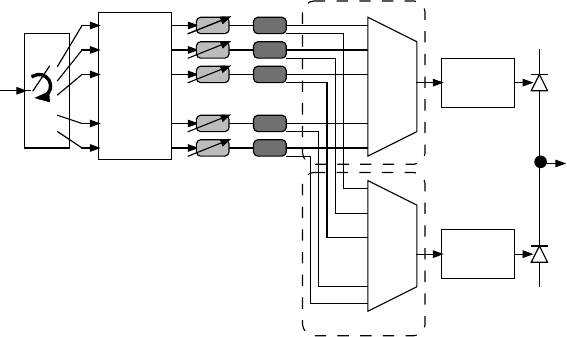
wavelength filters and sensors. Shown in Figure 2.22 is a FBG-based, 2-D tunable
wavelength-time encoder introduced by Chen [81]. Tunability is achieved using an
optical router with an array of multiple FBG fibers. While M different rows are de-
signed with different FBG arrangements for generating M different wavelength-time
codewords, a 1 ×M optical router is used to route an incoming narrow, broadband

Optical Coding Schemes 77
1 x M
optical
router
:
:
optical
circulator
narrow
broadband
optical
pulse
wavelength-
time code
absorbers
:
:
...
...
...
...
λ
1
−λ
Ν
λ
4
λ
1
λ
2
λ
7
λ
5
λ
2
λ
1
λ
3
λ
2
λ
5
λ
8
λ
N
λ
6
λ
1
λ
7
λ
3
array of M in-fiber FBGs
FIGURE 2.22 2-D tunable wavelength-time encoder with in-fiber FBGs [81].
optical pulse to one of these rows. The optical circulator routes the generated code-
word to the encoder output.
When a narrow, broadband optical pulse is injected into a section of FBGs, the
input wavelength, which matches the Bragg wavelength
λ
B
= 2n
ef f
Λ of the FBGs,
will be reflected, but the rest of the wavelength s will pass throug h the FBGs, where
Λ is the resonance grating period and n
ef f
is the effective index of the unmodified
mode [34, 78, 81]. Because there are multiple sections of distinct-Bragg-wavelength
FBGs within a piece of optical fiber, the location of each section determines the
time position of a certain wavelength pulse in a wavelength-time codeword. In addi-
tion to the setup in Figure 2.22, a limited degree of tunability can also be achieved
by introducing equal strain to the FBGs in a piece of optical fiber such that these
FBGs see the same amount of Bragg-wavelength shift. The amount of wavelength
shift in a FBG is determined by ∆
λ
shift
= 0.8
λ
B
(∆L/L),whereL is the FBG length
and ∆L is the amount of fiber stretch. For example, a typical section of FBGs is of
length L = 10 mm, and the maximum amount of strain that can be created is about
∆L = 0.1mm,giving∆L/L = 0.01. At
λ
B
≈1550 nm, the corresponding wavelength
shift is about ∆
λ
shi f t
≈ 12.4nm.Assumethatthespacingbetweenadjacentwave-
lengths is 0.8 nm (or 100 GHz in frequency), the number of available wavelengths
obtained by straining the FBGs can be as high as 12.4/0.8 = 15. By mounting in-
fiber FBGs onto a piezoelectric transducer for strain induction, different wavelength-
shifted codewords, such as those in the shifted carrier-hopping prime codes in Sec-
tion 5.3, are generated.
2.10.3 Arrayed Waveguide Gratings
Shown in Figure 2.23 is a tunable AWG-based coding device thatcanbeusedto
generate 1-D spectral-phase codes, 1-D spectral-amplitudecodes,and2-Dspectral-
temporal-amplitude codes. This device features four kinds of tunability. The first
kind of tunability is on the spreading and rotation of the spectral components of
broadband optical pulses. It is achieved by the use of an optical router in conjunction
with the wavelength periodicity of the AWG [57–60,77]. For an M ×M AWG device

78 Optical Coding Theory with Prime
with per iodic-wavelength assignment, exit wavelengths at the output ports are rotat-
able, depending on which input port is injected with a br o adband optical pu lse. The
1 ×M optical router is used to route an incoming pulse to one of the M input ports
of the AWG device. The second kind of tunability is supported by tunable delay-
lines along each wavelength path for temporal coding. The third kind of tunability is
provided by phase modulators for phase coding. The fourth kind of tunability is due
to the use of intensity modulators for preserving or droppingopticalpulsesinsome
wavelength paths. The properly wavelength-shifted, time-delayed, phase-modulated,
and/or intensity-mo d ulated pu lses are finally com b in ed at the WDM MUX to gen-
erate the desired 1 - D spectral-phase codeword, 1-D spectral-amplitude codeword, or
2-D spectral-temporal-amplitude codeword.
tunable
delay-
lines
:
:
:
:
:
:
:
:
M x M
AWG
2
3
M
2
3
M
11
1 x M
optical
router
braodband
optical
pulses
1-D/2-D
optical
code
λ
1
−λ
M
WDM
MUX
phase
modulators
intensity
modulators
input
ports
output
ports
FIGURE 2.23 Tunable A WG-based encoder for 1-D spectral (phase and amplitude) coding
and 2-D spectral-temporal coding.
TABLE 2.3
Periodic-Wavelength Assignment of an 8×
×
×8AWG
Output Port
12345678
input port 1
λ
1
λ
2
λ
3
λ
4
λ
5
λ
6
λ
7
λ
8
input port 2
λ
2
λ
3
λ
4
λ
5
λ
6
λ
7
λ
8
λ
1
input port 3
λ
3
λ
4
λ
5
λ
6
λ
7
λ
8
λ
1
λ
2
input port 4
λ
4
λ
5
λ
6
λ
7
λ
8
λ
1
λ
2
λ
3
input port 5
λ
5
λ
6
λ
7
λ
8
λ
1
λ
2
λ
3
λ
4
input port 6
λ
6
λ
7
λ
8
λ
1
λ
2
λ
3
λ
4
λ
5
input port 7
λ
7
λ
8
λ
1
λ
2
λ
3
λ
4
λ
5
λ
6
input port 8
λ
8
λ
1
λ
2
λ
3
λ
4
λ
5
λ
6
λ
7
For an M ×M AWG device with wavelength periodicity, the exit wavelengths,
denoted
λ
(i+ j) mod M
,atoutputport j can be represented as a modulo-M addition de-

Optical Coding Schemes 79
termined by which input port i is injected with a broadband optical pulse, where i and
j ∈ [1, M].Forexample,consideran8×8AWGdevice.Assumethattheexitwave-
lengths at the output ports j = {1,2, 3,4,5,6, 7,8} are {
λ
1
,
λ
2
,
λ
3
,
λ
4
,
λ
5
,
λ
6
,
λ
7
,
λ
8
},
respectively, when input port i = 1isinjectedwithanopticalpulse.Then,theexit
wavelengths at the output ports j = {1,2,3,4, 5,6,7, 8}are rotated once and become
{
λ
2
,
λ
3
,
λ
4
,
λ
5
,
λ
6
,
λ
7
,
λ
8
,
λ
1
},respectively,wheninputporti = 2receivestheoptical
pulse. Table 2.3 tabulates the wavelength at each output portofthis8×8AWGde-
vice as a function of which input port (or row) is applied with abroadbandoptical
pulse. By turning the optical router to the desired input portandtappingintotheap-
propriate output ports, the spectral components of an optical pu lse can be separ ated
and rotated rapidly.
TABLE 2.4
Transmission Wavelengths of Spectral-Amplitude Code BasedontheMaximal-
Length Sequences of Length 7 and Walsh Code of Length 8
Maximal-Length Sequences Wavelength Usage
C
1
(+1,+1,+1,−1,−1,+1,−1)
λ
1
λ
2
λ
3
λ
6
C
2
(−1,+ 1, +1,+1,−1,−1,+1)
λ
2
λ
3
λ
4
λ
7
C
3
(+1,−1,+1,+1,+1,−1,−1)
λ
1
λ
3
λ
4
λ
5
C
4
(−1 + 1,−1,+1,+1,+1,−1)
λ
2
λ
4
λ
5
λ
6
C
5
(−1,− 1, +1,−1,+1,+1,+1)
λ
3
λ
5
λ
6
λ
7
C
6
(+1,−1,−1,+1,−1,+1,+1)
λ
1
λ
4
λ
6
λ
7
C
7
(+1,+1,−1,−1,+1,−1,+1)
λ
1
λ
2
λ
5
λ
7
Walsh Codes Wavelengths Usage
C
1
(+1,−1,+1,−1,+1,−1,+1,−1)
λ
1
λ
3
λ
5
λ
7
C
2
(+1,+1,−1,−1,+1,+1,−1,−1)
λ
1
λ
2
λ
5
λ
6
C
3
(+1,−1,−1,+1,+1,−1,−1,+1)
λ
1
λ
4
λ
5
λ
8
C
4
(+1,+1,+1,+1,−1,−1,−1,−1)
λ
1
λ
2
λ
3
λ
4
C
5
(+1,−1,+1,−1,−1,+1,−1,+1)
λ
1
λ
3
λ
6
λ
8
C
6
(+1,+1,−1,−1,−1,−1,+1,+1)
λ
1
λ
2
λ
7
λ
8
C
7
(+1,−1,−1,+1,−1,+1,+1,−1)
λ
1
λ
4
λ
6
λ
7
To generate 1-D spectral-amplitude codes based on the maximal-length sequence
(+1,+1,+1,−1 , −1,+1, −1) of length 7, the encoder is configured with M = 7,
all delay-lines being set to give zero time-delay, and th e phase modulators giving
zero ph ase shift. In this configur ation, every “+1” element in the maximal-length
sequence is transmitted with a wavelength that is determinedbythe“+1” element’s
position. The “−1” elements are not transmitted, which is done by turning off the
intensity modulators along the corresponding wavelength path. So, the resulting
spectral-amplitude codeword C
1
contains
λ
1
λ
2
λ
3
λ
6
.Thereexisttotally7orthogonal
80 Optical Coding Theory with Prime
spectral-amplitude codewords {C
1
,C
2
,C
3
,...,C
7
} by cyclic-shifting this maximal-
length sequence, as given in Table 2.4 [10]. Codeword C
i
is generated when the 1 ×7
optical router is turned to input port i ∈ [1,7] of the 7 ×7AWGdevice.
To generate spectral-amplitude codes based on the “+1” elements of other bipo-
lar codes, such as Walsh codes and “modified” maximal-length sequences of length
M [49, 59, 60 ], wavelength periodicity of the AWG is not useful.(Themodified
maximal-length sequences of length N are constructed b y padding a “−1” to the
ends of every maximal-length sequences of length N −1inordertohavethesame
number of “+1” and “−1” in each sequence.) By setting the 1 ×M optical router
to one input port and all delay-lines to zero time shift, code generation is tunable
through the use of the intensity modulators to select which wavelengths to preserve
or drop [16]. Also given in Table 2.4 are Walsh code of length 8,whereas8wave-
lengths are used to represent the “+1” elements in the codewords in accordance to
the “+1” element’s positions.
Similarly, for 1-D spectral phase coding of bipolar codes, the phase modulators
come into play in o r der to ad d
π
phase shifts to the “−1” elements of the codes.
For 2-D spectral-temporal amplitude coding, time spreadingisachievedbytunable
delay-lines in addition to the wavelength selection by the intensity modulators. Vari-
ations of this tunable spectral encoder have been proposed for various optical coding
schemes in [57–60].
:
:
:
:
:
:
:
:
M x M
AWG
2
3
M
2
3
M
M-1 M-1
11
1 x M
optical
router
1-D or
2-D
optical
codes
WDM
MUX
balanced
photodetectors
1x2
optical
switches
WDM
MUX
:
:
optical
sampler
optical
sampler
true
conjugated
data
bits
tunable
delay-
lines
FIGURE 2.24 Tunable A WG-based optical balanced receivers for 1-D spectral (phase and
amplitude) coding and 2-D spectral-temporal coding.
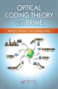
Figure 2.24 shows a tunable optical balanced recei ver that can be used to correlate
1-D spectral-phase codes, 1-D spectral-amplitude codes, and 2-D spectral-temporal-
amplitude codes. Th e r eceiver consists of a 1 ×M optical router, an M ×M AWG
device, a set of M tunable delay-lines and 1 ×2opticalswitches,twoWDMMUXs,
two optical samplers, and a pair of balanced photodetectors.Becauseeachreceiver
is assigned with one 1-D or 2-D spectral codeword as its address signature, the top
..................Content has been hidden....................
You can't read the all page of ebook, please click here login for view all page.