
Optical Coding Schemes 71
rate service in order to support the rate 1/T
d
= 1/(r
1
T
v
)=1/(r
1
NT
c
).Similarly,the
lowest-rate service (i.e., voice) requires codewords of r
1
r
2
times longer than that of
the video service in order to support the rate 1/T
s
= 1/(r
1
r
2
T
v
)=1/(r
1
r
2
NT
c
).To
support these three types of services, 1-D or 2-D unipolar codewords of lengths N,
r
1
N,andr
1
r
2
N are con structed with the same max imum cross-correlation fu nction
that is independent of code length [33, 34, 64–68]. The shortest codewords are then
assigned to the real-time services (i.e., video) with the highest bit-rate and prior-
ity, whereas the longest codewords are for the voice services. Because the analyses
in Chapter 7 show that the shortest codewords have the best performance, the QoS
of critical real-time video transmission is guaranteed. This unique priority feature,
however, cannot be found in conventional single-length coding schemes. In addition,
one system clock and lasers with the same pulse-width can be used for all types
of services in this multilength approach, simplifying system hardware and timing
requirements.
Furthermore, two multirate asynchronous O-CDMA schemes were proposed by
Maric and Lau in [87]. For example, in the parallel-mapping multiple-code scheme
[69, 87], each user is assigned multiple 1-D codewords. If a user needs to transmit at
arateofM times the basic bit rate, every M serial bits are first converted into M par-
allel bits. Then, each parallel bit 1 is conveyed b y one of the assigned M codewords,
but nothing is transmitted for a bit 0. As a result, the number of codewords that are
transmitted at the same time ranges from 0 to M,dependingontheuser’sbitrateand
the number of parallel bit 1s after the serial-to-parallel conversion. Because of the
need of transmitting many codewords simultaneously, optical codes with huge car-
dinality are required in this scheme. Nevertheless, the scheme is still asynchr onous
in nature because user-to-user synchronization is not needed, even though multiple
codewords are simultaneously transmitted by every u ser.
2.9 MULTICODE KEYING AND SHIFTED-CODE KEYING
To support higher bit-rate transmission without increasingthespeedofopticsand
electronics, three methods of multiple-bit-per-symbol transmission have been pro-
posed [70–75]. In pulse-position modulation (PPM) coding, each bit period is di-
vided into 2
m
nonoverlapping PPM frames [70,73]. Each user is assigned onedistinct
(address) codeword and all m serial data bits are conv erted into one of 2
m
possible
symbols. A symbol is transmitted by placing the code word entirely inside one of the
2
m
PPM frames designated for that symbol. As illustrated in Figure 2.16, every two
serial data bits are grouped to form one of the four possible symbols and, in turn,
the symbol is conveyed by transmitting the codeword entirelywithinoneofthefour
PPM frames. As a result, the total number of time slots is increased by a factor of 2
m
in this nonoverlapping PPM scheme and so is the transmission bandwidth.
Another m e th od of transmitting symbols is by means of multicode keying
[69, 75, 76 ], in which each user is assigned 2
m
distinct codewords to represent m
serial data bits per symbol. One of these codewords is conveyed each time in order
to represent the transmission of one of the 2
m
symbols. Figure 2.17 shows an ex-
ample of fo ur-co d e keying, in which every two serial data bitsaregroupedtoform

72 Optical Coding Theory with Prime
!"#$%&'()*+,-./0123456789:;<=>?@ABCDEFGHIJKLMNOPQRSTUVWXYZ[]^_`abcdefghijklmnopqrstuvwxyz{|}~
0 1
1 1
0 0
1 0
t
t
t
t
2 data
bits
t
t
t
t
4 symbols
= 4 PPM
frames
R bits/s
T
b
= 1/R
R/2 symbols/s
2T
b
FIGURE 2.16 Example of PPM coding with 4 symbols, represented by 4 PPM frames, where
T
b
is the bit period and R is the bit rate [70, 71, 73].
0 1
1 1
0 0
1 0
t
t
t
t
t
t
t
t
R bits/s
T
b
= 1/R
R/2 symbols/s
2T
b
2 data
bits
4 symbols
= 4 PPM
frames
FIGURE 2.17 Example of multicode keying with 4 symbols, represented by 4 distinct code-
words, where T
b
is the bit period and R is the bit rate [69, 75, 76].
one of the four possible symbols and, in turn, the symbol is conveyed by one of the
four distinct codewords. This multicode-keying approach does not need system-wise
synchronization but only needs the communicating transmitter-receiver pair be syn-
chronized, the same r eq uirement as any asynchronous OOK coding scheme anyway.
However, multicode keying r e quires an 2
m
-fold increase in the number of codewords,
all with the same low cross-correlation fun ction. Details about the cross-correlation
requirements and the prime codes that are suitable for multicode keying can be found
in Section 5.6.
Without the need for huge code cardinality, shifted-code keying assigns each user
with one codeword and its 2
m
−1(timeorwavelength)shiftedcopiestorepresentthe
2
m
symbols of m serial data bits per symbol [69, 74]. Figure 2.18 shows an example
of shifted-code keying with 4 symbols, in which 4 time positions (within a bit pe-
riod) are used as the transmission start-time of a codeword. This scheme is different
from the nonoverlapping PPM scheme [70, 73] in such a way that no increase in the

Optical Coding Schemes 73
0 1
1 1
0 0
1 0
t
t
t
t
t
t
t
t
R bit/s
T
b
= 1/R
R/2 symbol/s
2T
b
2 data
bits
4 symbols
= 4 PPM
frames
FIGURE 2.18 Example of shifted-code keying with 4 symbols, represented by shifting a
codeword to one of the four time positions, where T
b
is the bit period and R is the bit rate
[69, 74].
number of time slots or the bandwidth expansion is needed. TheoverlappingPPM
scheme in [71,72] belongs to a case of the shifted-code-keying scheme. Shifted-code
keying does not require system-wise synchronization or a 2
m
-fold increase in code
cardinality. Depending on time or wavelength shifts, two tunable transmitter-receiver
designs are given in Figures 2.19 and 2.20 [74]. The prime codes that are suitable fo r
shifted-code keying can be found in Section 5.3.
tunable
delay-line
tunable 1-D or 2-D
optical encoder
tunable 1-D or 2-D
optical decoder
electrical
data bits
optical
sampler
2
m
time-postion
synchronizer
photodetector & electronic
decision circuit
transmitter
:
:
:
:
:
:
:
:
recovered
data bits
optical pulses
receiver
one station
P/S
converter
S/P converter
star
coupler
electrical path
optical path
FIGURE 2.19 Tunable transmitter and receiver for shifted-code keying with time-shifted
codewords.
Shown in Figure 2.19 is a tunable transmitter and receiver forshifted-codekeying
with 1-D or 2-D time-spreading codewords an d their time- shi fted copies [74]. The
transmitter consists of a serial-to-parallel (S/P) data-to-symbol converter, a tunable
delay-line, and a tunable 1-D or 2-D optical encoder. The S/P data-to-symbol con-
verter groups every m serial data bits to form one of the 2
m
symbols. A narrow laser
pulse is then delayed to one of the 2
m
time positions by the tunable delay-line; the
74 Optical Coding Theory with Prime
amount of time-delay depends on wh ich sym bol is transmitted.Thedelay-lineonly
needs to be tuned as fast as the symbol rate and consists of the improved serial en-
coder in Section 2.1 [ 8 3, 84] . This optical pulse is then passed throug h the tunable
optical encoder to form the address codeword of its intended receiver with the prop er
amount of time shift. The r eceiver consists of a tunable 1- D or2-Dopticaldecoder,
an optical sampler, a 2
m
time-position synchronizer, a photodetector, an electronic
decision circuit, and a P/S symbol-to-data converter. Because only one time-shifted
codeword is transmitted du ring o ne symbol period , the intended receiver will see
at mo st one autocorrelation peak per symbol period, but the peak’s time position
depends on which symbol is received. Time-gated by the 2
m
time-position synchro-
nizer, the optical sampler inspects the existence of such a peak at these 2
m
positions.
The optical sampler consists of optical interferometric d evices, such as terahertz opti-
cal asymmetric demultiplexers and nonlinear optical loop mirrors [88,89]. These de-
vices can periodically generate an optical sampling window of size as narrow as sev-
eral picoseconds by means of ultrafast optical no nlinear effects. So, they can be used
to gate very narrow optical features, such as autocorrelation peaks, which appear at
most once in each symbol p eriod. Optical signals, such as noise and cross-correlation
functions, falling outside the sampling windows are dropped. The received symbol
is then determined by the electronic decision circuitry after ph o to d etection. Finally,
the data bits are recovered at the P/S symbol-to-data converter.
electrical data bits
bank of L
photodetectors
& electronic
decision circuit
transmitter
:
:
:
:
receiver
1 x L
power
splitter
tunable 2-D optical encoder
tunable delay-lines
L
x L
AWG
:
:
tunable
2-D
optical
decoder
S/P & symbol converters
L
x 1
optical
router
:
:
:
:
:
:
:
:
one station
star
coupler
electrical path
optical path
optical
pulses
recovered data bits
P/S converter
FIGURE 2.20 Tunable transmitter and receiver for shifted-code keying with wavelength-
shifted codewords.
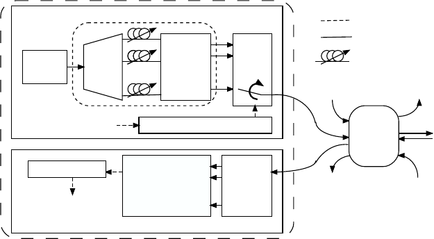
Shown in Figure 2.20 is a tunable transmitter and receiver forshifted-codekey-
ing with 2-D wavelength-time codewords and their wavelength-shifted copies [74].
These 2-D wavelength-time codewords are assumed to have L distinct wavelengths,
and each wavelength is u sed at most once p er codeword, such as the wavelength-
shifted carrier-hopping prime codes in Section 5.3. Because L wavelengths can gen-
Optical Coding Schemes 75
erate at most L wavelength-shifted copies of a codeword, 2
m
-ary shifted-code key-
ing requires 2
m
≤ L.ThetransmitterconsistsofanS/Pdata-to-symbolconverter,
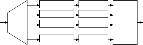
an L ×1opticalrouter,andatunable2-Dopticalencoder.Theencoder, which gen-
erates wavelength-shifted codewords, consists of a 1 ×L power splitter, a set of L
tunable delay-lines, and an L ×L arrayed-waveguide-gratings (AWG) device with
periodic-wavelength assignment [57–60,77]. Wavelength periodicity means that exit
wavelengths at the AWG output ports are rotatable, dependingonwhichinputportis
injected with a laser pulse. Assume that the wavelengths of the pulses at output ports
1, 2, 3, and 4 are
λ
1
,
λ
2
,
λ
3
,and
λ
4
,respectively,wheninputport1ofa4×4AWG
device is injected with a broadband optical pulse. The wavelengths of the pulses are
then rotated up once and become
λ
2
,
λ
3
,
λ
4
,and
λ
1
,atoutputports1,2,3,and
4, respectively, when input port 2 is injected with the pulse.Inthisencoder,anar-
row, b roadband laser pulse is first split into L pulses at the power splitter, and these
pulses are delayed by the tunable delay-lines, according to the address codeword of
its intended receiver. All possible wavelength shifts of thecodewordareperformed
at the L ×L AWG device. Depending on which symbo l is tran smitted, only one of
the AWG output ports, which has the proper wavelength-shifted codewo r d , is p icked
by the L ×1opticalrouter.
The receiver consists of one tunable 2-D optical decoder, a bank of L photodetec-
tors, an electronic decision circuit, and a P/S symbol-to-data converter. The decoder,
which has an identical setup as the encoder, is used to reversetheamountsoftime
delay and wavelength shift introduced by its corresponding encoder. Because only
one wavelength-shifted codeword is transmitted during one symbol period, the in-
tended receiver will see at most one autocorrelation peak persymbolperiodatone
of the L output ports of the optical decoder. By identifying which output port has
the autocorrelation peak, the received symbol is finally determined by th e electronic
decision circuitry after photodetection. Finally, the databitsarerecoveredattheP/S
symbol-to-data converter.
2.10 ENABLING HARDWARE TECHNOLOGIES
2.10.1 Wavelength-Aware Hard-Limiting Detector
WDM
DEMUX
λ
2
λ
3
λ
L
λ
1
hard-limiterphotodetector
hard-limiterphotodetector
hard-limiterphotodetector
hard-limiterphotodetector
electronic
decision
circuit
recovered
data bits
:
:
:
:
:
:
sampled
correlation
function
after optical
decoder &
sampler
FIGURE 2.21 Wavelength-aware hard-limiting detector for 2-D wavelength-time codes
[91].
As studied in Chapter 1, a hard-limiter can be placed at the front end of an optical
..................Content has been hidden....................
You can't read the all page of ebook, please click here login for view all page.