Chapter 6. Evolution and Benefits of SDX and NFV Technologies and Their Impact on IoT
Topics covered in this chapter include
■ A Bit of History on SDX and NFV and Their Interplay
■ Software-Defined Networking (SDN)
■ Network Functions Virtualization (NFV)
A Bit of History on SDX and NFV and Their Interplay
The seminal concepts behind software-defined networking (SDN) can be traced back to the 1990s. The Internet grew exponentially during that period, and it marked the beginning of an inexorable journey that would transform our lives forever. The synergies between information and communication technologies found a home in the Internet, giving rise to the digital revolution. According to several historians and experts, that digital revolution will have a much bigger impact on society than the industrial revolution of the 19th century.
This was a time when everything seemed possible, so many researchers and young companies advocated for a faster pace of innovation. However, the process for bringing new architectures and protocols to the marketplace was cumbersome and slow. For instance, network control planes in the 1990s were not programmable at all, and moving new technologies into production required very slow standardization processes. In light of this, some thought leaders proposed a new model, shifting from conventional black-boxed network protocols and control planes to a more open and programmable paradigm. One initiative that gained substantial traction was active networking. It was one of the first solid steps toward making computer networks more open and flexible, by introducing programmable functions into the network itself. The research and development (R&D) efforts around active network architectures blossomed in the mid-1990s. Unfortunately, the “Everything Is Possible” slogan of the late 1990s led to excessive investment and speculation. Many companies that were developing Internet technologies hit a wall in the early 2000s with the dot-com bubble. The motto became exactly the opposite, and lack of investment drove many companies to bankruptcy. As a result, R&D efforts around programmable networks ceased almost completely by the early 2000s. Although it is fair to say that active networks have set the basis for open and programmable control planes, SDN needed to wait for better times to materialize.
In the mid-2000s, a recession took hold after the collapse of the dot-coms. The problems surrounding network programmability again attracted the attention of the research community. The work carried out by Nick McKeown and Martín Casado of Stanford University, and Scott Shenker of University of California, Berkeley, on control and data plane separation led to the development of open interfaces between these two. This initiative was a game changer in the field of network programmability, and it ultimately resulted in the design of the OpenFlow (OF) API and protocol. Many people consider the fundamental contributions of these researchers to be the beginning of modern SDN technologies. In 2011, Nick McKeown and Scott Shenker helped found the Open Networking Foundation (ONF) as a way to ensure the development of an open community centered on SDN and OF technologies. ONF is a nonprofit and operator-led consortium that focuses on leveraging the advantages of disaggregating network functions, the use of white-boxing technologies, and the development of open source software and standards (ONF is in charge of the OF standards).
The strengths of SDN reside primarily in the separation of the control and forwarding functions. By decoupling these functions, traffic flow through multiple networking devices can be managed by a central entity, called an SDN controller. This approach enables the abstraction of traffic control policies and the detachment of forwarding decisions from black-boxed network equipment and communication protocols. In other words, the devices in charge of traffic forwarding can be supplied by different vendors and be deployed in a distributed fashion, but the traffic through them can be controlled and enforced in a programmatic way through SDN controllers (for example, by a single centralized controller or a cluster for redundancy and reliability purposes). To achieve this, networking devices must support basically two things: an interface to communicate with the controller, and an internal means of translating and enforcing the control rules supplied by the SDN controller. The next section of this chapter covers these aspects.
The success of SDN laid the foundation for other initiatives that leveraged the strengths and flexibility offered by the software-defined paradigm, beyond the conventional scope of SDN. This gave rise to software-defined X (SDX), or the development of technologies whose central goal is to respond to market needs and bring innovations to production at the speed of software (instead of depending on slow cycles with hardware development or protocol standardization processes). Examples of well-established technologies in the SDX space are software-defined wide-area networks (SD-WAN), software-defined wireless networking (SDWN), and the digital transformation that we are starting to witness in many industries, gradually moving away from legacy hardware and embedded systems to adopt software-defined IoT (SD-IoT) solutions. SDN also revitalized interest in software-defined radio (SDR) and its modern variants in the context of 5G, such as the software-defined radio access network (SoftRAN).
A different effort that is often incorrectly mixed up with SDX is network functions virtualization (NFV). NFV started in the early 2010s and gained tremendous traction after an Industry Specification Group (ISG) of the European Telecommunications Standards Institute (ETSI) became the standard-bearer of this technology. Since the initial publications produced by ETSI, the technology has become a reference in both industry and the research community, to the point that is now hard to conceive of future network architectures, such as 5G networks, without NFV being part of them.
NFV relies both on IT and state-of-the-art virtualization to build virtualized network functions (VNF). These VNFs can be composed and connected (chained) to create blocks for implementing networking services. NFV should not be confused with server virtualization techniques; NFV aims to create communication services that go way beyond the scope of conventional server virtualization. One of the central objectives of NFV is to allow telecom operators and enterprises to transition from networks embodied by proprietary hardware appliances (such as traditional switches, routers, firewalls, or intrusion detection devices) to a model in which each of these functions can be implemented using one or more VNFs running on top of general-purpose servers.
The line that separates SDN and NFV is not clear to everyone. Unless you turn to specialized literature, the terms SDN and NFV are frequently used in tandem (as in SDN/NFV), which creates confusion about their respective roles, scope, and strengths. It is important to understand that SDN and NFV are not interchangeable terms. These technologies can benefit each other, but one does not depend on the other. SDN can be implemented and scale without any form of virtualization or NFV support, whereas VNFs and the virtualized communication services they support can be implemented without the need of an SDN controller. SDN and NFV address different problems and were devised with different objectives.
Although the separation of traditional SDN and NFV technologies is quite easy to illustrate, the limits between newer software-defined technologies under the SDX umbrella and NFV become fuzzier. For instance, the flexibility and benefits of leveraging NFV technologies for implementing SD-WAN solutions are substantial, so future WAN technologies will probably bet on more cohesive designs. Likewise, the advantages of leveraging SDX concepts in NFV infrastructures are incontestable. For instance, software-defined functions can more easily enable centralized orchestration, configuration, monitoring, and lifecycle management of VNFs and networking services in multivendor environments. In this sense, SDX can be seen as an enabler for NFV, whereas NFV represents one of the most promising and ambitious use cases for SDX. As Figure 6-1 shows, even though NFV can be implemented without SDX, and vice versa, their foremost strength lies in their intersection.

Figure 6-1 SDX and NFV: Two Different and Complementary Technologies That Can Benefit from Each Other
The rest of this chapter develops in more detail the strengths of SDX and NFV technologies both in isolation and combined, and also covers their roles as technology enablers for IoT, 5G networks, and the expected interplay between Fog and Cloud computing. Various aspects related to orchestration shall also be covered in this chapter, while the security facets of SDX and NFV will be addressed later in Chapter 7, “Securing SDN and NFV Environments.”
Software-Defined Networking
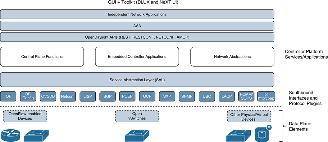
SDN seeks to bring the agility of modern software development and computing technologies to the networking field. This will allow IT departments to gradually decrease network architectures characterized by rigid control planes and static treatment of traffic flows, and instead use programmable control planes capable of offering the level of dynamicity and flexibility that the market is demanding. To achieve this, SDN proposes to decouple the “brain” from the “bodies” (see Figure 6-2). That is, SDN detaches the element that controls the policies and makes decisions about how traffic must be forwarded across the network infrastructure (the brain) from the elements in charge of forwarding the traffic (the bodies), based on the policies and rules supplied by the brain. This decoupling of control and forwarding functions is usually implemented using different devices: The brain is typically centralized and physically separated from the forwarding elements (the bodies), whereas the bodies can be distributed in such a way that a single brain can manage multiple forwarding elements simultaneously.

Figure 6-2 shows that the SDN architecture is stratified in three layers: the infrastructure supporting the data plane, the SDN controllers, and the Application layer.
■ Infrastructure layer (data plane): Included in this layer are the physical devices in charge of forwarding traffic across the network. These devices are endowed with processing capabilities and forwarding functions that are exposed and managed by an external SDN controller through the southbound API in Figure 6-2. The internal implementation of the data plane can vary from device to device because they might have different processing functions and traffic forwarding engines (for example, when the infrastructure consists of devices supplied by different vendors). The forwarding policy enforced in the infrastructure layer can be categorized into three groups, or forwarding modes.
Reactive mode: In this mode, the SDN controller pushes a new forwarding rule to a device whenever required. For instance, every time a packet arrives at a switch, a flow table lookup is performed. If no matching rule is configured on the switch defining how to process and forward the packet, the switch typically generates an exception and forwards either the header or the entire packet to the SDN controller using the southbound interface in Figure 6-2. The SDN controller decides the forwarding policy and pushes a rule into the switch, enabling the processing of not only the specific packet, but also subsequent ones belonging to the same traffic flow. Therefore, in this operation mode, the SDN controller basically reacts to exceptions and pushes traffic forwarding rules only when needed.
Proactive mode: The SDN controller populates in advance the necessary rules for processing and forwarding all possible traffic flows. In strict proactive mode, incoming packets either find a matching entry in the switch or are discarded. When the rules have been pushed to the switch, the role of the SDN controller is relegated merely to monitoring and performance supervision. The advantage of this mode is that all packets can be forwarded at the line rate.
Hybrid mode: This mode basically combines the best of the previous two modes. It is one of the most widely used modes because it can offer line-rate forwarding capabilities for part of the traffic without losing the flexibility of generating exceptions and pushing new rules for new (unexpected) traffic flows.
The next two sections delve into the internals of the infrastructure layer, with special focus on OpenFlow (OF) switches in general and the Open vSwitch (OVS) implementation in particular.
■ SDN control layer: This layer consists of a logically centralized entity called the SDN controller. As shown in Figure 6-2, the SDN controllers expose a northbound API to a set of specific functions (programs) running in the application layer. These applications are the ones that bring the desired level of programmability on top of the controllers, thereby offering the possibility to innovate in the networking field at the speed of software. The SDN controllers also exploit the southbound API exposed by the infrastructure layer to control the forwarding behavior on the data plane. In essence, an SDN controller implements the control plane logic and supports the northbound and southbound APIs, with the objective of performing the following actions:
Providing an abstract view of the network to the SDN application layer. The northbound API enables the SDN controller to expose an abstracted and technology-independent view of the infrastructure to higher-level applications.
Receiving requirements from the SDN application layer.
Translating the requirements received from the application layer to specific configuration rules that can be pushed down to the infrastructure layer.
Receiving and processing events from the infrastructure layer and performing monitoring of the network infrastructure.
An SDN controller is a logically centralized entity. Note that this does not preclude scenarios in which multiple controllers can coexist and be clustered for controlling a given network. The reasons for employing multiple SDN controllers can vary, but the main drivers are fundamentally the following:
■ Reliability: For example, deploying a cluster of SDN controllers can maintain the control plane operative even if one SDN controller fails or gets compromised.
■ Scalability: For instance, multiple SDN controllers can be deployed when the network is large enough that it requires some sort of segmentation in different areas of control, each managed by an individual (active) controller. These controllers can be arranged in different ways, depending on the requirements (hierarchy, mesh, partial mesh, and so on). Settings including a federation of hierarchically arranged SDN controllers, with communication interfaces between them based on open standards will become commonplace in the SDN arena.
■ SDN applications: These must not be confused with traditional applications in the TCP/IP network stack. These applications represent a set of functions that were specifically programmed to capture forwarding policies and perform surgical control on the packets and their corresponding traffic flows across the infrastructure layer. The applications express the desired behavior and policies to be applied to the SDN controller via the northbound API. To this end, the applications use the abstracted view of the infrastructure supplied by the SDN controller. SDN applications typically comprise the logical functionality behind the policies and decision-making process that must be enforced through the SDN controllers, as well as a set of northbound drivers to connect to different SDN controllers (for example, in cases where the controllers are supplied by different providers). Note that only one driver is required if the application always connects to the same controller.
■ Southbound API: This interface supports communication between the SDN controller and infrastructure devices. This API enables programmatic control of packet processing and forwarding rules across the device fabric. It also provides mechanisms for generating events (for example, an exception is sent to the controller when no matching rule is found after a lookup process), as well as for reporting monitoring information. A well-known protocol implementation supporting this southbound interface is OpenFlow, which offers an open, standardized, and vendor-agnostic interface that enables interoperability among a broad range of infrastructure devices and SDN controllers.
■ Northbound API: This interface supports communication between the SDN controller and the applications on top. As mentioned previously, the SDN controllers exploit this API to expose an abstracted (technology-agnostic) view of the network to the applications, while the applications communicate through the API the desired behavior and policies that need to be enforced. Different forums and standardization bodies are actively working on the definition of open, standardized, and vendor-agnostic northbound APIs to enable interoperability among applications and controllers.
The strengths of the model described previously are summarized as follows:
■ Highly programmable networks: Policy definition and flow control remain decoupled from forwarding functions and the inherent details of packet processing within infrastructure devices. This enables a new generation of open and highly programmable control planes, which can exercise full control over traffic processing functions and forwarding decisions with packet-level granularity.
■ Agility: Innovations in the form of new control protocols and mechanisms can be tested and brought to market at the speed of software.
■ Openness: Network owners can exploit different groups of applications, SDN controllers, and infrastructure devices that can be supplied by totally different vendors. This flexibility is possible thanks to the different levels of abstraction enabled by the proper segmentation of functions and roles and well-defined APIs and protocols. In SDN, the infrastructure is basically exposed to the application layer as a single (logical) resource fabric, allowing administrators to control or change the behavior of the network programmatically via open APIs.
■ Centralized configuration and view that simplifies operation and management (OAM): SDN architectures tend to follow simpler designs, which can potentially simplify OAM tasks substantially. The logically centralized model offered by SDN gives network administrators a single source of truth for configurations, a single policy decision point (PDP) that can push rules to a set of distributed policy enforcement points (PEP), and a unified and global view of the network (which obviously simplifies operational tasks). Moreover, the behavior and control of the traffic are managed by SDN controllers working in tandem with a pool of applications instead of vendor-specific devices and protocols. Administrators can thus initialize, configure, secure, and manage the lifecycle of network resources via applications (programs), which can be developed either by a third party or by the administrators themselves. Clearly, the strengths of centralizing the intelligence and operation also create critical dependencies: If the centralized elements fail, the whole network is at risk. Hence, SDN controllers and applications are attractive targets for attackers. Chapter 7 covers the potential vulnerabilities and security aspects of SDN architectures in detail.
OpenFlow
OpenFlow (OF) is the first widely accepted SDN implementation enabling the networking industry to open the control of L1/L2 switches, routers, mobile base stations, Wi-Fi access points, and more. Unlike the conventional black-box approach to design and control networking equipment, which ruled the networking industry for more than two decades, OF offers a programmatic interface to control the behavior and traffic flow across the network infrastructure.
A few years ago, everything seemed to indicate that OF would become omnipresent. However, OF implementations have not yet taken off commercially—at least, not at the time of this writing. But that is not the point. The strength of OF lies in its paradigm and an open implementation that the industry embraced as a reference model. It brought an unstoppable wave of SDN with it, and it has already created a second wave with SDX. Most likely, we will witness this second wave hitting the IoT space relatively soon. Overall, the model pushed by the OF community changed the mentality of many stakeholders along the networking value chain, including telecom companies, network administrators, software companies, and hardware vendors.
This critical mass surrounding the innovations brought by OF fostered the creation of the Open Networking Foundation (ONF). This organization is responsible for defining OF standards. The documents released by ONF include the specification of the OF architecture, which mainly consists of three components: an OF switch, an OF controller, and the OF protocol, which enables reliable and secure communication between the OF switch and the OF controller. Communication reliability is ensured by using TCP as the transport protocol; communication security is handled by TLS, which enables authentication and ensures the privacy and integrity of the communication between an OF controller and the OF switches. Through the OF protocol, a controller can enforce both the path followed by packets of a given flow across the network and institute a set of actions that can change the packets (such as the packets’ headers) as needed.
Figure 6-3 illustrates the three main components of the OF architecture. The OF controllers are depicted at the top. The central part of the figure shows the internals of an OF switch, which communicates with the OF controllers on the top using the OF protocol. The OF protocol enables OF controllers to create, read, update, or delete flow entries from the flow tables (entries can be matching rules or actions). As mentioned in the previous sections, this can be accomplished in three operation modes: reactive, in response to packets that do not match any of the existing rules in the tables; proactive, with the OF controller pushing all the forwarding rules in advance; or hybrid, with proactive behavior for certain flows and reactive behavior for the rest. Packets that match a rule can be forwarded at wire speed in the switch fabric, whereas packets that are unmatched need a different treatment. In the reactive and hybrid modes, the packets can be forwarded directly to the controller; in strict proactive mode, they are discarded. For packets that reach the controller, the controller can decide to add a new rule to a flow table, modify an existing one, discard the packets, or even forward the packets itself, as long as the OF switch is configured to forward the entire packets to the controller (not just the headers). This is particularly relevant when high-speed communications are required because the TCP/TLS communication back and forth between the OF switch and the controller obviously introduces non-negligible overhead.

As shown in Figure 6-3, an OF switch consists of one or more flow tables connected in series, a group table, a meter table, and one or more OF channels connecting to external controllers. For reliability reasons, an OF switch might be connected to multiple controllers. This allows an OF switch to remain operative even if the active controller or the communication with it fails. External means are obviously required to ensure coordination among controllers, especially to avoid uncoordinated control on the switch or to synchronize controller handoffs.
Each flow table in an OF switch contains a set of flow entries, which consist of a set of match fields and instructions that must be applied to any matching packet. Flow entries match packets in order of precedence, meaning that the first matching entry found in a flow table is the one that will be used. The matching process starts at the first flow table in the pipeline; depending on the outcome, it might continue to subsequent ones in the series. If a matching entry is found, the instructions associated with the specific flow entry are executed. On the other hand, if no matching entries are found, the actions to be applied on a packet depend on the operation mode configured in the OF switch (reactive, proactive, or hybrid mode).
The main function(s) of the elements shown in Figure 6-3 are summarized as follows:
■ OpenFlow channel: Element that supports the interface between an OF controller and an OF switch. An OF channel supports only one external OF controller, which the controller then uses to control the switch.
■ Forwarding process: Encompasses the actions required for processing and transferring a packet to an output port (or set of output ports, as in the case of flooding).
■ Pipeline: Set of flow tables connected in series, providing the means for examining, matching, and modifying packet fields and transferring the packets to an output port within an OF switch. Packet processing within the pipeline typically stops when a match is found and the instructions associated with the matching entry do not specify a next flow table. In that case, the packet is often modified and transferred to the corresponding output port.
■ Meter table: A meter element within an OF switch that can measure the rate of packets and enforce rate-limiting policies on a traffic flow.
■ Flow table: Entity that contains flow entries and represents one of the possible stages in the pipeline.
■ Flow entry: Element in a flow table that provides the match fields and the instruction set required to match and process packets. The instruction set in a flow entry can either contain actions or modify the pipeline processing. For instance, the actions in an instruction can describe packet-forwarding actions, modifications that need to be applied to a packet, or the need for group table processing. A flow entry can forward a packet directly to a physical port.
■ Group table: Entity that specifies additional processing, such as sets of actions that need to be applied for more complex forwarding semantics (flooding, link aggregation, multipath forwarding, and so on). As mentioned in the previous point, the actions defined in a flow entry can send packets to a group table. This level of indirection enables common output actions for different flow entries to be applied and changed efficiently. In a nutshell, a group table consists of a list of action sets and some means of selecting which of those action sets to apply on a per-packet basis. The packets sent to the group can be subject to the application of one or more action sets.
Network vendors can freely decide how to implement the internal components of an OF switch, as long as their specifications conform to the OF protocol and the semantics for matching and executing actions on packets are respected. For instance, a flow table lookup might be performed in different ways between vendors. Depending on the implementation, this lookup process could be done using software-based flow tables (as with Open vSwitch) or in hardware by implementing the flow tables directly in an ASIC.
Open Virtual Switch
The previous section outlined the main components of the OF architecture, including key features of an OF switch. This section focuses on Open vSwitch, one of the most successful and widely adopted implementations of a software-defined switch that supports OF. Open vSwitch (often abbreviated as OVS) is an open-source implementation of a multilayer, software-based switch that was especially conceived for virtual environments. It is now part of several virtualization and cloud computing platforms (including OpenStack and OpenNebula), making OVS one of the SDN implementations that is actively used in the NFV space (observe that OVS is one of the elements in the intersection of SDN and NFV in Figure 6-1).
OVS was designed to address some of the well-known limitations of existing hypervisors. On Linux-based hypervisors, the traffic between external systems and local VMs is typically bridged using built-in L2 Linux bridges. Linux bridges are very effective in single-server environments, but they are not well suited for multiserver virtualization deployments, which is typically the case in cloud computing settings. In these environments, the dynamics on the number of nodes joining or leaving the network can be high; in many cases, part of the network ends up connected to special-purpose switching hardware. OVS was designed to support virtualized networks that can be distributed across multiple physical servers.
The multilayer nature of OVS refers to the fact that the switch supports several different protocols and capabilities at different network layers, such as the following:
■ OF protocol, including specific extensions to support virtualization
■ IPv4 and IPv6
■ IPsec
■ NetFlow and IPFIX
■ Link Aggregation Control Protocol (LACP), IEEE 802.1ax
■ IEEE 802.1Q VLANs and trunking
■ GRE tunnels
■ VXLAN
■ Traffic policies per VM interface
■ Multicast snooping
■ Bonding, load balancing, active backup, and Layer 4 hashing
Figure 6-4 depicts the OVS architecture. OVS consists of three main elements:
OVS daemon, called ovs-vswitchd: Runs in user space and can control several OVS forwarding planes within one machine. A single instance of the daemon is intended to run per machine because it can handle all the necessary elements around the OVS forwarding plane.
OVS database, called ovsdb-server: Also runs in user space and offers a lightweight database to maintain the switch tables and the configuration of the flow tables in the kernel. Both the ovs-vswitchd daemon and external clients and/or controllers can communicate with ovsdb-server using the OVSDB management protocol. The protocol can be used either to issue queries about the switch configuration or to manipulate its tables.
OVS data path: Implemented at the kernel level and provides a fast path for traffic forwarding.

As Figure 6-4 shows, the OVS daemon supports a northbound OF interface, enabling external control of an Open vSwitch by means of an OF controller. In this way, a centralized OF controller can create a logical view of multiple OVSs running on separate physical servers and expose them to the upper application layer (refer to Figure 6-2). Because OVS supports OF, each OVS instance internally implements a multitable forwarding pipeline and also supports the “match-action” OF mechanisms described in the previous section. Note that an OF controller can interact both with the OVS daemon and with the database directly. The example in Figure 6-4 also shows how traffic generated by external systems is forwarded to an internal virtual machine (VM).
Figure 6-4 captures one of the first solid interplays between SDN and NFV in industry. As described previously, an OVS is basically a virtual switch that can be decomposed into three main functions (ovs-vswitchd, ovsdb-server, and OVS data path), each of which implements a specific set of network-related tasks. When we look at OVS through the lens of NFV, it becomes clear that, in the NFV terminology, each of these functions is actually a virtual network function (VNF) whose configuration and behavior can be managed by an SDN controller.
Another important aspect of OVS resides in the options available for managing traffic flows. Figure 6-4 shows one of these options for traffic received from an external endpoint that needs to be forwarded to an internal virtual machine (VM). In this case, the match-action process applied to the first packet of a new flow will yield a “match miss,” generating an event (an exception) that needs to be sent to the ovs-vswitchd daemon running in user space. When ovs-vswitchd determines the matching rules that need to be pushed to the OVS tables, it inserts the necessary entries in the OVS data path (such as to flow tables in the kernel). Subsequent packets of the flow will match these entries and be forwarded following the fast path shown in the figure.
An alternative technique is to enable traffic offloading and let the hardware chipsets take control and do the heavy lifting. This is an appealing feature because it allows OVS to control both a software-only implementation of the switch and one enabling hardware support. In this latter case, the match-action process applied in hardware to the first packet of a new flow again yields a “match miss.” As a result, an event is generated and, in this case, reaches the OVS kernel module. This yields a “match miss” as well and generates an event for the ovs-vswitchd daemon in user space. As in the earlier case, ovs-vswitchd will determine the matching rules and, based on the offload policy, it will push the corresponding entries to the flow tables implemented in programmable hardware. Subsequent packets of the flow will hit these entries and be forwarded without reaching the OVS kernel module. Note that the example illustrated in Figure 6-4 shows the basic operation of OVS, without considering OVS offloading.
Other relevant features and benefits worth highlighting for OVS include the following:
■ OVS was designed to offer a programmatic means of facilitating configuration automation in virtualized network deployments.
■ OVS offers support for VM migration, including not only static state such as network configuration (ACLs, tunnels, and so on), but also live network state.
■ The OVS database supports remote triggers, which can be used to monitor the network and generate events to an orchestration system that can instrument automated actions based on the event.
■ Since 2012, the Kernel implementation of OVS is part of the Linux kernel mainline.
■ As mentioned previously, OVS can operate both as a software-only switch and on dedicated switching hardware. Thanks to its flexibility, it has been ported to several switching chipsets and to hardware and software virtualization platforms.
Despite these strengths, OVS also has limitations. The performance of the software-only version of OVS is one of them. This is especially critical because it can become one of the first bottlenecks upon flooding attacks. In light of this, both industry and academia are actively working on mechanisms to improve the performance of software-based switches, both with and without hardware support, while also adding new techniques and tool sets for programmability. Vector Packet Processing (VPP) is one of these initiatives; it represents one the most promising advances in the evolution of software-defined switches and routers.
Vector Packet Processing
Vector Packet Processing (VPP) is a technology created by Cisco and is one of the main components of the open source initiative FD.io (Fast Data–input/output). FD.io (https://fd.io) is part of the Linux Foundation and is actively working on developing a “universal data plane.” More specifically, FD.io consists of a set of projects aimed at expanding the scope and reach of data plane programmability. The primary objective is to develop more ambitious software-defined packet processing techniques that can run on general-purpose (commodity) hardware platforms, covering bare metal, containers, and VMs. Aspects such as high throughput, low latency, and high efficiency in terms of I/O are at the heart of FD.io, and VPP is key to achieve these goals.
VPP has been implemented as an extensible open source library providing switching/routing functionality. It represents a paradigm shift in the way software-based functions can process and forward packets. Unlike traditional scalar processing methods, in which pipelines are designed for processing one packet at a time, VPP supports processing a “vector of packets” in parallel. Scalar processing techniques suffer from a number of issues, mainly caused by the context switching produced by nested calls within the routines developed to process I/O interrupts. In general, the result of these routines is one of the following actions: punt a packet (the term punt, introduced by Cisco, indicates the action of sending a packet down to the next-fastest switching level), drop the packet, or rewrite and forward the packet. The problem is that each packet incurs an identical set of steps and potential instruction cache (I-cache) misses. A cache miss while reading from an I-cache generally leads to the largest delay because the thread of execution needs to stall until the instruction is fetched and retrieved from main memory. This entails context switching and thrashing entries in the I-cache. The way to improve this in traditional scalar packet processing systems is to introduce larger caches.
VPP mitigates this problem. The larger the size of the vector, the lower the processing cost per packet because I-cache misses are amortized over a longer period of time. Clearly, there are disadvantages as well if the size of the vector is too large. For example, depending on the implementation, the process might need to wait until the vector is filled in, thus losing the merits of prefetching packets into the data cache and the time saved when I-cache misses occur.
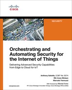
Figure 6-5 shows the fundamentals of VPP. It is based on a directed graph that consists of two different types of nodes. Input nodes are the ones used to inject packets into the directed graph; graph nodes are the ones implementing core packet processing functions. The packets are processed in batch and in parallel, and they are forwarded through the nodes in the graph in vectors. In this process, the packets are classified and then sent to different nodes in the graph, depending on their category. For instance, non-IP Ethernet packets go to the ethernet-input node and IPv6 packets go directly to the ipv6-input node, saving cycles in that way. All packets in the vector are processed together until they have all gone through the graph.
As shown in Figure 6-5, VPP offers a multilayer switch (L2–L4) that was designed to run on commodity multicore platforms. One of the main advantages versus some of its predecessors, such as OVS, is its high performance. Its current implementation can handle more than 14 million packets per second (MPPS) on a single core and support multimillion entries in its forwarding information bases (FIB), all while ensuring zero packet drops. To accomplish this, VPP can run a copy of the graph per core and exploit batching processes while efficiently caching packets in memory. It works in run-to-completion mode (avoiding context switching), and it runs in user space (also avoiding any form of mode switching, such as user mode to kernel mode). In terms of security, VPP is endowed with both stateless and stateful security features, including security groups, stateful ACLs, port security, and role-based access control (RBAC).
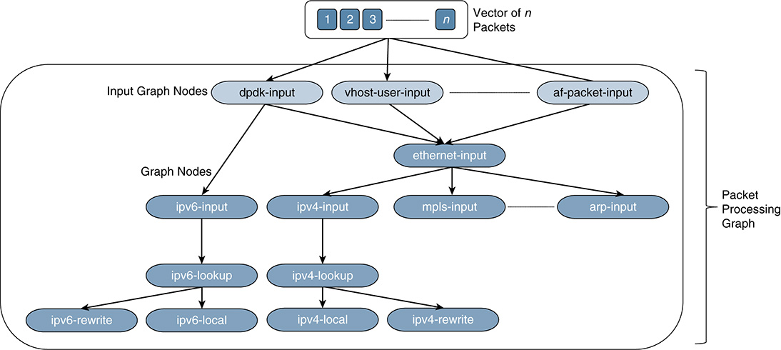
Figure 6-5 Directed Graph of Nodes Used for Processing a Batch of Packets (a Vector of Packets) in Parallel
The modularity of the VPP library is one of the key aspects facilitating data plane programmability. Because the VPP engine runs in user space, developers can add packet-processing capabilities and extend VPP without needing to modify code at the kernel level. Indeed, developers can insert new nodes into the VPP graph to build new packet-processing solutions. Because VPP is open source, anyone can develop new graph nodes and plug-ins for it. This approach also enables more advanced scenarios, by combining VPP with other solutions in the marketplace (for example, to build a highly efficient load balancer for OVS).
As shown in Figure 6-5, VPP leverages Intel’s Data Plane Development Kit (DPDK; see the input node at the top left in the graph). This approach has also been followed by OVS, which is being ported to DPDK as well. The union of VPP and DPDK is expected to accelerate NFV data planes and reach performances that were impossible to obtain with scalar processing techniques. VNFs requiring high I/O performance, such as virtualized deep packet inspection (DPI) systems and load balancers, are strong candidates to base their data plane designs on VPP, or at least borrow concepts from it.
Overall, VPP represents an important step in the evolution of software-defined switching and routing, enabling not only the transition from scalar-to-vector packet-processing techniques, but also the development of richer data plane programmability. The NFV community is enthusiastically looking at VPP and other recent technologies, such as P4 (Programming Protocol-Independent Packet Processors), which could have a big impact on the SDN and NFV arenas.
Programming Protocol-Independent Packet Processors (P4)
The evolution of SDN has opened a new era in the networking industry, but every big change has its challenges and side effects. Protocols such as OF were supposed to become pervasive, but OF adoption is occurring at a much slower pace than expected. In fact, other SDN projects that capitalized on its benefits, such as OVS, have gained more traction than OF itself. Part of the Internet community surmises that OF did not really take off because of the complexity associated with programmable forwarding planes. Enterprises and service providers need to evaluate the cost of such programmability and weigh the benefits of embracing OF. Pioneers in the SDN field, such as Nick McKeown, seem to have a different opinion and think that the lack of penetration is because OF fell short in its objectives and failed to take real control of the forwarding plane. Without proper means of programming and modifying the forwarding plane, changing the behavior of the packets and traffic flows remains a challenge. Whether it is because of cost and complexity or a lack of effective programming means, the reality is that OF has not reached the status that many anticipated.
Programming Protocol-Independent Packet Processors (P4) is partly a response to increase the level of control and programmability of the forwarding plane. It remains to be seen whether P4 will succeed in reducing the complexity and overcome part of the resistance OF faced. P4 is basically a high-level (declarative) language to express rules on how packets are processed by network elements, ranging from software switches to ASIC-based appliances, in a protocol-independent way. More precisely, P4 proposes an abstract model and a common language to define how packets are processed by different technologies, including virtual switches, FPGAs, ASICs, and NPUs.
As shown at the top of Figure 6-6, P4 can work in conjunction with an SDN control plane, and developers can create P4 programs that can be mapped to different devices using a P4 compiler. Whereas OF was fundamentally designed to control and populate forwarding tables in fixed function switches, P4 increases the level of programmability, allowing SDN controllers to define how the switch should behave. For instance, OF can operate on a predefined (that is, fixed) number of protocol headers, but it lacks the capability to add and control new headers dynamically. This is the functionality required to actually develop protocol-independent switches, so P4 was designed with the following goals in mind:
■ Reconfigurability: Programmers should be able to change the way packets are processed by switches, including actions such as redefining the packet parsing and processing functions themselves.
■ Protocol independence: Switches should be tied neither to specific network protocols nor to packet/header formats. Instead, the SDN control plane should be able to specify how to parse and extract new headers and specific fields, as well as define the set of “match+action” tables required to process those fields or the entire headers (see Figure 6-6).
■ Target independence: A P4 programmer should know neither the specific details of the underlying switch hardware nor its software. The role of the compiler is to map a target-independent program written in P4 to a target-dependent binary in order to instrument a specific switch configuration.
As Figure 6-6 shows, switches that support P4 can forward packets via a programmable parser, followed by multiple stages of match+actions tables between ingress and egress that can be arranged in series, in parallel, or as a combination of both. The role of the parser is to process the header of incoming packets. The match+action tables perform lookups on header fields and apply actions and packet modifications according to the first match entry found in each table. Overall, a P4 program focuses on the specification of the parser, the match+action tables, and flow control through the pipelines, to define the switch configuration for any protocol implemented by a P4 programmer.
Unlike OF, which relies on a fixed parser, P4 supports a programmable parser. This parser allows new headers to be introduced and controlled whenever needed. Furthermore, in OF, the match+action tables operate in series, whereas in P4, they can be implemented and combined in parallel. The challenge is obviously how to find a balance between the desired level of expressiveness and programmability and the complexity of implementing it in practice across a variety of appliances and software switches.
The forwarding model in P4 is controlled by two main operations: configure and populate. The configure operations are the ones in charge of programming the pipeline (defining the set of match+action stages) and specifying the header fields that need to be processed at each stage. This determines the protocols that are supported and how the switch will process the packets. The populate operations determine the policy applied to the packets by adding or removing entries to and from the match+action tables that were defined during a configuration operation. These day 1+ configuration operations are usually referred to as runtime rules.
In a nutshell, a P4 program specifies the following elements:
■ The fields and size of each header within a packet
■ The header sequences allowed within a packet
■ The type of lookup to perform, including which input fields need to be used and the actions that can be applied
■ The dimension of each table
■ The pipeline, including the tables layout and the packet flow throughout the pipeline
■ A parsed representation on which match+action tables apply to each packet
■ The set of ports to which the packets will be sent
■ The queuing mechanisms
■ The egress pipeline and the resulting packet to be transmitted
An aspect worth highlighting is that the initial implementations in the marketplace are betting on switch silicon and optics on P4-enabled appliances instead of pure software switches. Nevertheless, the debate about whether P4 will overcome some of the challenges faced by OF will continue for the next few years.
Although the technologies analyzed so far are mainly focused on switching architectures, the evolution of SDN gave rise to much more ambitious paradigms that have gone far beyond packet processing and switching fabrics. The next three sections describe initiatives related to software-defined technologies that have certainly raised the bar of what it is possible to achieve through software in the networking and telecommunications industries.
OpenDaylight
The push for SDN and increased network programmability gave birth to a number of open source initiatives at almost every layer of the network stack. OpenDaylight (ODL) is considered a mature project that addresses the development of this new stack. Thanks to its progress, it has become a reference in the open networking industry. In a nutshell, ODL is a Linux Foundation Project that coordinates the development, distribution, and maintenance of probably the largest and most comprehensive open source SDN platform available at the time of this writing. The initiative started in 2013 and currently includes more than 50 organizations. It has a solid developer community composed of more than a thousand contributors actively working on the platform; according to the ODL foundation, the code base has around a billion subscribers, which makes it the most popular open SDN platform worldwide.
One of its central objectives is to deliver a programmable SDN framework that enables the combination and automation of protocols and networks of different sizes and shapes, while abstracting the details of the underlying network infrastructure from application developers. ODL is driven by a collaborative community that fosters openness and vendor neutrality. Its current release, called Oxygen, is the eighth version of the platform released by the ODL foundation. The last releases mainly focused on the development of extensions and enhancements to support three promising areas for SDN: IoT, Metro Ethernet, and cable operators. In this way, ODL has expanded its scope over the years and has applied automation of programmable networks to use cases beyond traditional networking settings (for example, in the IoT space).
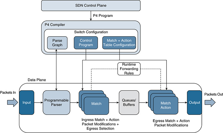
Figure 6-7 shows a simplified version of the ODL reference architecture. ODL was designed as a modular and extensible platform to support a large number of use cases combining SDN and NFV solutions. To better understand its reach, we describe it using a bottom-up approach. The architecture consists of the following layers:
■ Southbound interfaces and protocol plug-ins: As shown at the bottom of Figure 6-7, this layer interfaces with the physical and virtual infrastructure. It supports a wide variety of protocols, including different versions of OF, OVSDB, NETCONF, LISP, and BGP. It also includes specific protocols in the IoT space, such as COAP. Each of these protocols has its own plug-in, which can be dynamically linked to the Service Abstraction Layer (SAL) on top. The SAL exposes the device services to the upper layers (the SDN controllers and applications). The SAL is obviously a fundamental part of the ODL controller platform because it bridges the gap between the SDN applications located northbound the SAL and the SDN devices managed through the plug-ins mentioned previously. Observe that ODL supports OF-enabled devices as well as OVSs, along with many other physical and virtual elements (routers, access points, load balancers, and so on).
■ A Model-Driven Service Abstraction Layer (MD-SAL): In ODL, network devices and applications are all elements represented by a model—more specifically, a YANG model. The interactions between these elements occur within the SAL, which provides the adaptation mechanisms and enables data exchange between a network device and an SDN application (both of which are abstracted and represented as YANG models). This approach offers a formal and standardized specification of the capabilities of a network device or an application, in a machine-readable way. A key advantage is that SDN applications are not exposed to the specific details of the device, such as its particular CLI implementation—nor do they need those details to communicate with the device. As long as the SAL has access to the YANG models that abstract and stipulate the communications northbound with the applications and southbound with the devices, the data exchange and configurations mediated through the SAL are guaranteed. In ODL terminology, the SAL basically enables the communication between the producer and consumer models. A producer model implements an API and provides data through it. A consumer model gets data through the API. The role of a producer or consumer depends on the data to be exchanged. For instance, a protocol plug-in and its associated model act as a producer when supplying information about the underlying network to the upper layers. When the SDN applications send configuration instructions to networking elements via the SAL, the corresponding plug-ins receiving the data act as consumers. In this way, the SAL enables SDN applications to take control of the configuration of physical and virtual elements in the network. In general, the SDN applications that implement the business logic and algorithmic decisions consume the functions and resources offered by the controller platform; they make decisions based on the information gathered (in some cases, in real time) and use the controller platform again for pushing rules onto the network infrastructure. An orchestration system is key to enable all these operations, leveraging the abstractions (models) and interfaces (plug-ins) offered by a collection of dynamically pluggable modules to ODL’s SAL. The SAL and its YANG-based/model-driven nature are the secret sauce and the biggest differentiator in ODL, making it the de facto standard open source SDN control platform in industry. In summary, the SAL does the following:
■ Matches producers and consumers based on its data stores and the requests received through the different APIs running in the platform. Thanks to the SAL, consumers can find a given producer, trigger remote procedure calls (RPC) to get data from the producer, or be discovered and receive notifications or configuration commands from producers whenever needed.
■ Enables and instruments the exchange of information between producers and consumers. A producer can insert data into SAL’s storage; a consumer can read data from SAL’s storage. The SAL’s data store handles both operational and configuration data.
■ The ODL controller platform: This layer offers the control plane functions, a set of controller applications embedded in ODL itself, and the network abstractions required for controlling and managing the network infrastructure and its protocols. As outlined shortly, this layer also contains a group of modules that enable orchestration functions in ODL. For instance, this includes the integration of OpenStack Neutron, which offers functions that an orchestration system can use to automate the configuration of devices, thereby offering products such as networking as a service. More specifically, this layer has three constituent blocks:
■ Control plane functions: Modules for managing OF switches, OF forwarding rules, OF statistics, processing topologies, L2 switches such as OVS, Link Aggregation Control Protocol (LACP) and Locator/ID Separation Protocol (LISP) services, and more.
■ Embedded controller applications: An ecosystem of control applications offered by ODL. These applications can run in ODL itself. An installation of ODL does not need to pick them all, so an ODL instance can be quite lightweight, if needed. Among the applications ODL offers are Cardinal (monitoring), Controller Shield (security/anomaly detection), DOCSIS abstraction (for cable services), EMAN (energy management), NetIDE (client/server multicontroller engine that also integrates with an IDE for software development and testing), Neutron (OpenStack’s network manager), and Virtual Tenant Network (VTN) manager (enables the management of multitenant virtual networks).
■ Network abstractions: An ecosystem of applications that enable policy control, including separating the what (the intent) from the how (the instantiation process that maps to the desired intent). This block includes functions such as NEMO (domain-specific language enabling the abstraction of network models), the Application-Layer Traffic Optimization (ALTO) protocol manager, and Group-Based Policy (GBP) services (inspired by promise theory and based on the work initiated by Mike Dvorkin toward the decoupling of high-level policy definition from its specific implementation).
■ ODL APIs: These are a set of northbound APIs offered on top of the controller platform, including REST, RESTCONF, NETCONF, and AMQP interfaces.
■ Authentication, authorization, and accounting (AAA): Security is a key focus area for ODL. The platform provides a framework for AAA, as well as automatic discovery and securing of network devices and controllers. Security is part of a larger charter that, in ODL terminology, is called S3P (Security, Scalability, Stability, and Performance). The ODL community is constantly improving the code base across all its projects in the areas of S3P. Development and testing groups team together to assess how any new change impacts the S3P of the ODL platform. The ODL foundation is also working with the Open Platform for NFV (OPNFV) project to support a trial environment that could offer performance tests for SDN controllers in a realistic way.
■ Independent network applications: A set of SDN applications that could be implemented by any software developer. These leverage the abstractions and native functions offered by the ODL platform to build ambitious software-defined networks. This is the layer where the orchestration system would reside.
■ OpenDaylight User Experience (DLUX) application and the NeXT toolkit: DLUX mainly manages aspects such as allowing users to log in to the ODL platform, get node inventory, view statistics and the network topology, interact with YANG data model stores, and configure elements such as OF switches through ODL. The NeXT UI, on the other hand, is a toolkit that Cisco developed and contributed to the ODL community. It provides the means to perform multiple actions and configurations centered on the network topology. NeXT is an HTML5/JavaScript toolkit that is used to draw and display network topologies (including different layout algorithms), visualize traffic and paths, and enable user-friendly configurations. Figures 6-8 and 6-9 show snapshots of the NeXT UI for BGP and ACL configurations through ODL plug-ins.
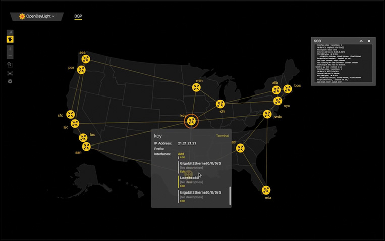

Figure 6-9 Another Example of OpenDaylight’s NeXT UI Toolkit—in This Case, the Configuration of an ACL
ODL’s code is now part of various solutions and SDN applications that are commercially available. To implement a new SDN application, developers typically need to follow these steps:
Add/choose a set of southbound protocols plug-ins.
Select some or all of the modules offered by the ODL Controller Platform, such as control plane functions, embedded or external controller applications (recall that some of them might be contributed by the open source community and, therefore, might not necessarily become part of ODL’s distribution), and network abstractions and policies.
Build controller packages around a set of key ODL components, such as the MD-SAL and YANG tools. YANG tools offer the necessary tooling and libraries to support NETCONF and YANG.
As an open source project, ODL represents a dynamic environment. Therefore, it is essential to ensure that new software components can be deployed and tested without interfering with mature and thoroughly tested code. To this end, ODL leverages Apache Karaf. Among other functions, Apache Karaf helps coordinate the lifecycle of microservices, manage logging events related to the infrastructure, and enable the remote configuration and deployment of microservices in production environments with proper levels of isolation. ODL also uses other successful service platforms, such as the OSGi framework and Maven, to build packages that manage the features and corresponding interactions between components enabled by Apache Karaf. The modular design of the platform facilitates the reutilization of services created by other developers. This modular approach also allows developers and users to install only the ODL services and protocols they need.
Another important aspect of ODL has to do with its contribution to model-driven SDN architectures. In particular, ODL represents a transition in industry from API-driven service abstraction layers (AD-SAL) to model-driven ones (MD-SAL), and this approach has become a distinctive factor of ODL’s SAL. Table 6-1 compares API-driven and model-driven SALs.
Table 6-1 Comparison of an API-Driven SAL (AD-SAL) and a Model-Driven SAL (MD-SAL) (Adapted from the Article “Difference Between AD-SAL and MD-SAL”)
API-Driven SAL |
Model-Driven SAL |
|---|---|
Routing requests between producers and consumers using the SAL APIs and data adaptations required are all statically defined at compile/build time. |
Routing requests between producers and consumers using the SAL APIs are defined by machine-readable models, and data adaptations are handled by internal plug-ins. The API code is generated directly from the models when a plug-in is compiled. When the plug-in OSGI bundle is loaded into the controller, the API code is loaded into the controller as well, along with the rest of the plug-in code containing the model. |
Northbound and southbound APIs are typically present in an AD-SAL even for functions and/or services that are mapped 1:1 between northbound plug-ins and southbound plug-ins. |
An MD-SAL enables the northbound and southbound plug-ins to use the same API, which is generated from a model. Any plug-ins can become an API (service) producer or consumer as needed by a specific application (captured in the model). |
In AD-SAL there is typically a dedicated REST API for each northbound and southbound plug-in. |
Instead of being needed to develop dedicated APIs, an MD-SAL can provide a common REST API to access data and functions defined by the models. |
An AD-SAL provides request routing functionality and selects a southbound plug-in based on the service type. It may also provide service adaptation for northbound (service, abstract) APIs, whenever these are different from their corresponding SB (protocol) API. |
An MD-SAL also provides request routing functionality and the infrastructure to support service adaptation. The difference is that the service adaptation functions are not provided by the SAL itself; they are provided by external adaptation plug-ins, which are implemented just as any other service plug-in in ODL. |
In an AD-SAL, request routing is resolved by plug-in/service type. An AD-SAL knows which node instance is served by which plug-in. For instance, when a northbound service plug-in requests an operation on a given node, the request is routed to the appropriate plug-in, which then routes the request to the appropriate node. |
Request routing in an MD-SAL is achieved based on both protocol type and node instances because node instance data is exported from the plug-in into the SAL. |
An AD-SAL is stateless. |
An MD-SAL can store data for models defined by plug-ins. Producer and consumer plug-ins can exchange data through the MD-SAL data store. |
In an AD-SAL, services usually provide both asynchronous and synchronous versions of the same API method. |
In an MD-SAL, the same API can be used for both synchronous and asynchronous communications. MD-SALs usually encourage an asynchronous approach to application developers, but they do not preclude synchronous calls (e.g., mechanisms are available allowing a caller to block until the message is processed and a result is sent back). |
Figure 6-10 sketches a more detailed picture for the SAL and compares both models. For example, the AD-SAL routes requests from one of the northbound (NB) service plug-ins shown at the top of Figure 6-10 to one or more southbound (SB) plug-ins at the bottom. Even when the NB and SB plug-ins and APIs are essentially the same, in an AD-SAL, they still need to be defined and deployed.
We now consider a different scenario, in which one of the NB service plug-ins is using an abstract API to access services provided by one or more SB plug-ins. As shown in Figure 6-10, an AD-SAL can provide service adaptation and perform the required translations between the abstract NB API and the SB plug-in APIs.
In the case of an MD-SAL, the adaptation plug-in shown on the right side of Figure 6-10 is just another (regular) plug-in. As with any other plug-in, it produces data that is sent to the SAL and consumes data from the SAL through APIs that can be automatically rendered from models. In an MD scenario, the role of an adaptation plug-in is to perform model-to-model translations between two APIs; the data models can contain information to aid the routing process. Thanks to the model-driven approach, the SAL can support runtime extensibility because the APIs can be extended and regenerated without needing to stop any running service. The southbound and northbound interfaces and the associated data models can be crafted and created using YANG and can be stored in a repository within the SAL.
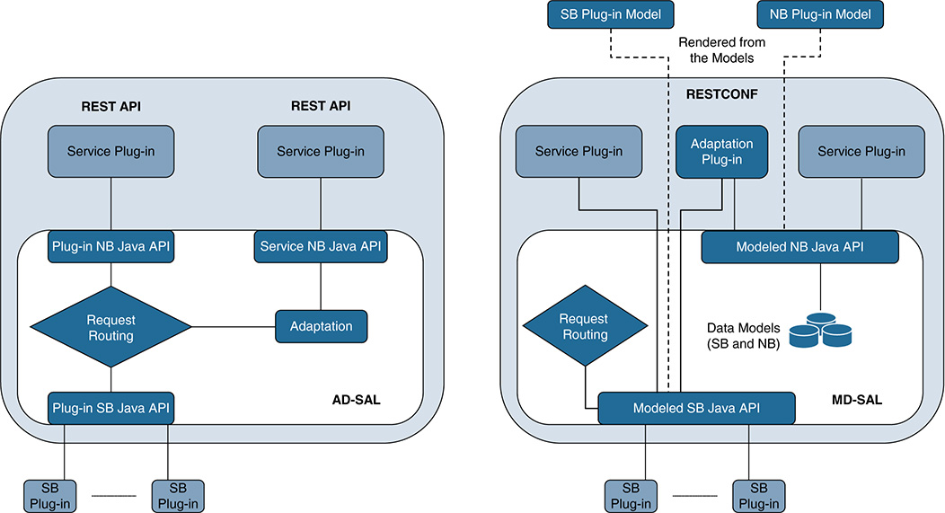
Figure 6-10 From an AD-SAL to an MD-SAL and Interactions Involving Northbound (NB) and Southbound (SB) Plug-ins and Services (Adapted from the Official ODL Site)
An important aspect is that the work being carried out by ODL is very well aligned and is highly complementary to the vision that the ETSI ISG group on NFV is pushing forward. The NFV vision has already gathered hundreds of telecom carriers and companies around the world. It seeks to leverage the utilization of off-the-shelf technology in building and composing virtualized network functions (VNF). Aspects such as deciding where to run those VNFs; performing the corresponding instantiations of computing, networking, and storage capacity required; and chaining these VNFs to build “networks” are clearly all central to NFV. ODL is a candidate to meet a number of these goals and provide SDN-based control for NFV settings. In this regard, ODL has already begun to work with the Open Platform for NFV (OPNFV) and is starting to become adopted by some content services providers (CSP) who want to deploy and control NFV settings using SDN. In fact, multiple operators and vendors are joining forces in hopes of integrating open source components contributed by different projects and creating a reference platform to accelerate SDN/NFV deployments. For instance, OPNFV has selected ODL mainly because of the following features:
■ Its openness and vendor-neutral nature.
■ Model-driven SAL and the mechanisms offered by ODL in support of a wide range of physical and virtual network functions and technologies.
■ Policy management support and intent-based features, as well as the capability to interface with external orchestration systems (for example, the one OPNFV supplies).
■ Network virtualization and service chaining capabilities. NFV forwarding graphs and service function chaining (SFC) are explained in detail later in Figures 6-15 and 6-16.
It is worth highlighting that ODL is actively contributing to the convergence of several open source projects and standards. For example, initiatives such as ODL, OpenStack, and FD.io have joined forces to create a framework called the Nirvana Stack, presented in 2017 at one of the OpenStack Summit events. The Nirvana Stack also leverages the liaison with OPNFV to provide a common means to orchestrate, deploy, and test VNFs and SFC within OpenStack. Furthermore, ODL toolchains for cloud, NFV, and programmability are becoming not only part of the core of other open source frameworks beyond OPNFV and OpenStack (such as the Open Network and Automation Platform [ONAP]), but also part of the architectures developed by standards bodies such as the Metro Ethernet Forum (MEF).
The modularity, programmability, and flexibility these new stacks offer can be applied to a growing number of use cases in the IoT space. Sectors such as smart cities, utilities, manufacturing, and transportation are undergoing a profound transformation and are transitioning from legacy systems to new IoT-centric architectures. Many of those different use cases represent a huge opportunity for SDN and NFV technologies, particularly for combined SDN/NFV architectures that can offer a uniform means to onboard, secure, and manage the lifecycle and communications of a large number of heterogeneous virtual and physical elements under a common management paradigm. ODL has accomplished part of this and is already supporting IoT-specific plug-ins, enabling its utilization in certain use cases. The architectural decisions that are being made about SDN and NFV, especially those related to orchestration and automation, will certainly influence future IoT architectures, such as those that embrace fog computing (Figure 6-21 to Figure 6-26 cover these aspects in detail).
After this succinct description of ODL’s role, its main components, and its interplay with various open source and NFV initiatives, it should become clear that ODL is the result of an industry move to accelerate and unfold the adoption of SDN, including the nascent application of SDN controllers to IoT use cases. It is worth highlighting that although ODL is a great example of industrywide collaboration and is a reference for SDN open source controllers, bringing it into production is still challenging in specific scenarios. Two of these reasons are that network service lifecycle management is lacking (it needs to be implemented at the application layer), and operationalization typically demands high skills (for example, professional services) instead of an easy-to-manage controller that most customers are looking for.
Extending the Concept of Software-Defined Networks
The success of SDN in the networking field rapidly captured the attention of the research community. Various systems that were traditionally implemented in hardware started to be re-examined, with the aim of assessing which components could be developed in software and become openly programmable. One area that embraced this approach is radio communications, with special emphasis on radio signal processing functions in software that need to interface with a hardware-based radio frequency (RF) module. The research efforts in this area keep growing steadily and lie under what is usually referred to as software-defined radio (SDR).
In a nutshell, SDR represents a paradigm shift in radio communication systems. Functions that for decades were implemented in hardware, such as digital tuners, modulators and demodulators, and multiplexers, are now being implemented in software. The idea of transitioning toward more software-oriented RF communications is older than modern SDN. Indeed, it is important to understand that SDR could live without SDN (although it is fair to say that SDN has revamped the interest in SDR and accelerated the efforts and investment around it).
Although both technologies can coexist, there are obvious benefits when they come together. Figure 6-11 illustrates a graphical example in which a switch supporting a software-defined radio base station is managed by an SDN controller.
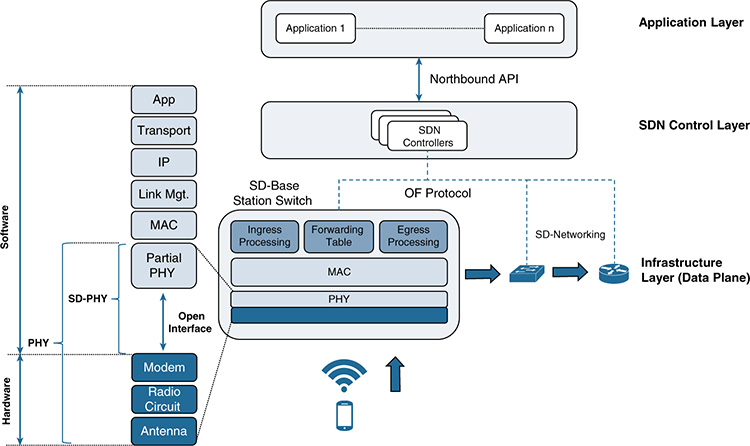
Figure 6-11 Example Showing a Radio Base Station Switch Integrating SDR at the PHY Layer, Managed by an SDN Controller
The central part of the figure shows a radio base station that provides services to mobile subscribers. The traditional three layers present in the SDN model are clearly visible in the figure (the switch, the SDN controller, and the applications on top). In the example, the switch that implements the radio base station supports the OF protocol. At the data plane level, it can forward traffic toward other SDN-enabled devices that also support OF (the software-defined L2/L3 devices shown on the right).
The left side of the figure shows the utilization of SDR and illustrates the differences between a traditional physical layer (PHY) and a software-defined PHY (SD-PHY). Whereas in legacy systems, basically anything below the MAC layer entails a hardware implementation, SDR gradually absorbs part of the functions in the PHY layer and implements them in software. In this particular example, the RF front end is implemented in hardware and supports the antenna, the lower-level radio circuits, and the modulation and demodulation functions. An open interface on top of it enables communication between the RF front end and a set of software-defined functions, which now implement part of the functionality of the PHY.
The combination of SDR and SDN has great potential because the software components offer much more flexibility to expose information from the RF module to an external SDN controller. Once processed by the SDN controller, the information can be used by the applications in the layer above to introduce innovations for topics such as power adjustment, cognitive radio, or capacity optimization. This example shows the synergies between SDR and SDN, but they target different problems and do not depend on each other. SDR follows a methodology that is essentially the same as the one used in SDN:
Decouple certain functionality at the data plane level from legacy (hardware-based) systems.
Implement those functions in software.
Make the implementation open and programmable so that the developer community can start innovating in the field.
Define interfaces and protocols in such a way that the data plane can be controlled and managed externally.
Another field in which software-defined technologies have gained substantial traction is wide-area networks (WAN). A WAN extends a computer network over large distances, from a few miles up to transoceanic distances. WAN technologies are largely used in the enterprise and public sectors to connect branch offices, headquarters, and data centers in different ways, depending on the requirements (for example, using a hub-and-spoke model, with the headquarters as the hub and branch offices as spokes, or a partial-mesh or even a full-mesh topology for reliability).
In traditional WAN schemes, the connection between sites requires purpose-built hardware. These devices support not only the links and protocols enabling the delivery of packets across the WAN, but also the mechanisms to guarantee the performance required by the applications and databases conducting the different business functions. In this regard, the expansion of networks across large distances poses multiple operational challenges; the larger the size of the network, the more difficult it becomes to manage the services across a WAN. Applications such as virtual desktops; streaming live media; and collaboration tools such as videoconferencing, voice, or virtual meeting rooms usually demand low latency and are sensitive to jitter and packet loss. Other applications, however, are more sensitive to bandwidth availability and network congestion, so the complexity and cost of expanding, managing, and troubleshooting an application portfolio on WAN environments tends to increase significantly as the network scales up.
These challenges became very evident as many applications started to migrate from privately owned IT infrastructures and data centers to public clouds. Before organizations adopted cloud-based solutions, a considerable part of their traffic was exchanged between branch offices and headquartered data centers and networks. With the rise of public clouds, traffic patterns changed substantially as more traffic involved the cloud directly. As a result, the rigidness of a WAN model based on dedicated and expensive links between sites, supported by specialized (proprietary) hardware, rapidly started to show its limitations. Many start-ups and vendors begun to develop a more flexible model tailored to the cloud, with the aim of offering increased agility while reducing cost. These efforts led to platforms that were better prepared to deliver services with high performance over the WAN. These new platforms are built on software-defined concepts and are categorized as SD-WAN solutions.
As with the evolution of SDR, the transition from legacy WAN technologies to modern SD-WAN followed the four steps listed previously. In the SD-WAN model, the control and configuration of the connectivity between sites are decoupled from the infrastructure devices that support the communications and protocols over the WAN. Controllers implemented in software are typically hosted in the cloud, allowing centralized configuration and operation and maintenance (OAM) tasks of a WAN in a simpler and more agile way. Again, the central idea resides in the separation (decoupling) of the control and configuration mechanisms from the devices supporting the WAN. A centralized controller is used to define and command the enforcement of a set of policies, including connectivity, reliability and failover mechanisms, security, and traffic prioritization. The SD-WAN controller can receive monitoring information about the status of the network and make decisions in real time to ensure that the applications meet the performance and service-level agreements (SLA) centrally defined.
Another important step in the evolution of WAN technologies is the integration of virtualization, making SD-WAN another area in which SDN and NFV are starting to converge. With the introduction of virtualization techniques in the WAN, some organizations are starting to replace traditional branch routers and physical appliances at the network edge with virtualized elements. This approach has several advantages for end customers. First, it substitutes expensive routing/switching hardware with virtualized appliances, not only to support the communications over the WAN, but also to provide the desired level of performance for the different applications. Second, SD-WAN technologies leverage consumer-grade Internet and cellular connections, which are typically far less expensive than dedicated enterprise-grade MPLS links (see Figure 6-12). The combination of these factors contributes to a reduced CAPEX associated with the WAN, offering much more flexibility in the way headquarters and branch locations communicate with each other and also with the applications running in the cloud. Third, SD-WAN solutions give customers centralized control of their connectivity and provisioning processes, security and VPNs, communication policies, application delivery, application-level performance, and SLAs, all in a simple and intuitive way. This streamlines operational tasks substantially. This approach not only reduces the OPEX associated with maintaining and scaling the WAN, but it also increases the elasticity to absorb and manage traffic in a more dynamic and cost-effective way, compared to legacy WAN solutions. Indeed, the tendency is to move toward a WAN as a service or network as a service model, in which the WAN configuration and the services running on it become more dynamic and are better suited to support models such as software as a service (SaaS) or infrastructure as a service (IaaS) in the cloud.

Figure 6-12 shows an SD-WAN scenario that combines multiple locations, including headquarters, campus, branch and small/home offices, public and private clouds, and data centers with different communications means and centralized control to build more flexible and cost-effective WANs. SD-WAN solutions are characterized by four basic elements, according to Gartner:
The capability to support different connection types, such as MPLS, consumer-grade Internet, and LTE wireless communications. Organizations can partially or wholly replace expensive (dedicated) links without impacting the performance of the applications supporting the business. This is one of the main drivers for SD-WAN: Reducing cost using less expensive communications is key for many organizations.
The capability to absorb and allocate traffic in a more flexible way, including dynamic path selection across different communication technologies (for example, for load sharing, resiliency upon link/node failures, traffic engineering, and QoS). This also includes performance optimization at the application level and the strategic deployment of servers and consumers, to reduce the overall network traffic across the WAN. The role of the cloud is fundamental in this regard: As the applications move to the cloud, a considerable part of the traffic is exchanged inside the cloud instead of traversing the WAN.
An intuitive interface (UI) that simplifies management tasks in a centralized way, including the configuration of connectivity, provisioning tasks, security, application optimization tools, and troubleshooting.
The integration of virtualization technologies, including the capability to create overlay networks on top of consumer-grade Internet and LTE communications and secure connections end to end through VPNs. This integration also refers to the capability to include third-party virtual appliances, such as WAN optimization tools, firewalls and intrusion detection systems, gateways, or other elements that are required to meet the SLAs defined.
SD-WAN started as many other software-defined solutions, by decoupling intelligence from proprietary (expensive) equipment and moving control to a central point in the cloud. Today the reach of SD-WAN is expanding constantly and, more importantly, policy control is becoming more sophisticated. Novel SD-WAN technologies are starting to separate the intent (what) from the specific instantiation process (how) and its location (where). This new approach, which is usually referred to as intent-based networking, is opening new frontiers on how to deliver business-class and secure services over a WAN in a simple and intuitive way for administrators.
Overall, the evolution of software-defined technologies has been marked by a clear tendency to decouple the “brain” from the “body.” Many existing SDX technologies have clearly gone beyond the limits of just controlling the data plane. As mentioned at the beginning of this chapter, SDX technologies can live without NFV, and vice versa, but their interplay is a game changer in the evolution of IoT and, more specifically, fog computing. Before we address these topics, the next sections describe the evolution of NFV and its strengths and benefits, including one of the most promising orchestration architectures in industry; we also look at some of the challenges the NFV community is facing today.
Network Functions Virtualization
The revenue of telecom operators (or service providers) has not been equal to the evolution of data traffic volume, especially over the past few years with the advent of broadband mobile networks and high-definition video. Currently, over-the-top (OTT) providers generally own the contents that produce the vast majority of the traffic exchanged in the Internet, so many telecom operators have been relegated to infrastructure and mobile providers. In other words, they have become the owners of both the pipelines and the means of enabling customers to consume content offered by third parties.
In most cases, revenues have been growing systematically year after year. This is mainly because of an increase in the number of services contracted by customers. For instance, a large fraction of teenagers and even kids have smartphones (meaning new contracts), which was not the case more than a decade ago. Today a standard family might subscribe to six or seven contracts, including broadband Internet, a fixed phone line, TV packages, and multiple mobile lines. The volume of contracts and revenues has certainly increased in absolute numbers, and the traffic volume and associated expenditures to cope with it have increased significantly as well.
As Figure 6-13 shows, revenues have been constantly decelerating, while data traffic is growing at a much higher pace. This is a well-known issue in the telecom industry, usually referred to as the revenue gap problem. Lower margins have impacted strategy and investment plans at almost every level in the telecom sector. Many operators have started a crusade to reduce cost, increase efficiency, and develop much more cost-effective service offerings, especially for enterprise customers, where margins can be higher.

NFV is the foundational model for achieving these goals. Since its inception, NFV was very well received by the telecom community. Specification and standardization efforts immediately found a home in the form of an industry specification group within ETSI. The concept is simple. As Figure 6-14 shows, NFV proposes implementing network functions in software in such a way that they can run on general-purpose (commercial, off-the-shelf) multicore servers instead of purpose-built appliances. The NFV platform is open by nature and is actively supporting and embracing software developed by the open source community. Several initiatives are underway to accelerate the adoption of NFV, as well as interoperability and compliance with ETSI’s NFV specifications.
Through virtualization, network functionality is now decoupled from specific equipment. Contrary to the conventional approach of using a different physical appliance for every network function (specific equipment for a switch, a CPE, a WAN accelerator, a firewall, an IDS, an AP, a RAN node, a PE router, and so on), which is costly and requires such considerations as a power supply and physical space and installation for each appliance, NFV enables the model on the right side of Figure 6-14. With NFV, a set of virtualized appliances can be deployed on general-purpose servers in a much more flexible way.

Figure 6-14 From Physical Appliances in Traditional Networking to Virtual Network Functions That Can Be Deployed on General-Purpose Servers
The benefits of NFV for telecom operators are summarized as follows:
■ OPEX reduction: NFV comes with the promise of standardized network orchestration and automation (the next sections cover this in detail). By automating the deployment and lifecycle management (LCM) of virtualized network functions in general-purpose hardware, operators can dramatically reduce the service creation and adoption times. Savings in terms of physical space are also important: With NFV, a single server can consolidate and run multiple VNFs instead of needing a separate physical appliance for each network function. Telecom providers also aim to simplify operational tasks; the automation offered by NFV can bring new levels of abstraction and capabilities so that operators do not need to deal with the intricacies of low-level management of virtual machines, Linux containers, operating systems, and so on. NFV automation is ultimately seeking true LCM, including creating, provisioning, updating, deleting, and monitoring networking services. That is, automation in NFV covers not only day 0 configuration of a service, but also day 1+ tasks along its lifecycle. NFV itself is necessary but not sufficient; personnel training and best-practice definitions are also utterly important to lower operational expenditures.
■ CAPEX reduction: By shifting from hardware- to software-based network functions, operators have the advantage of a much more open market. New players, such as software development companies, can become suppliers of VNFs that can be deployed on any server with the virtualization and performance capabilities an operator requires. This approach fosters openness and competitiveness and can considerably reduce capital expenditures. Moreover, by performing networking functions using standard (off-the-shelf) servers and storage, operators can reduce equipment costs. Economy of scale approaches for those offering their own cloud solutions means that some operators can benefit from much lower costs by buying at scale, as well as exercise resource scheduling, pooling, and sharing in a smarter way (for example, to deal with traffic peaks, especially unexpected ones).
■ Energy efficiency: Efficiency is also an important driver. Both the industry and the research community are actively working on greener data center models that have the capacity to reshuffle the virtualized setups and layouts to reduce power consumption. In this way, data traffic can be consolidated dynamically in fewer servers, depending on the demand, and unused servers can be gradually shut down until they are needed again. The improvement of live VM migration techniques, including the state at all levels (I/O, stateful ACL dependencies involving other VNFs, and so on), is the subject of many researchers’ studies.
■ Flexibility: With NFV, networks can be scaled out or scaled in at the speed of spinning up or down VMs or Linux containers. Network topologies are not restricted by the physical location of a specific appliance. For instance, if intrusion-detection capabilities are needed in a conventional networking environment where one IDS is already installed somewhere, then two options exist, depending on the requirements and specific setup: Buy a new physical IDS and install it where needed, or ensure that the physical network permits connecting to the existing IDS and that the switching and routing policies support configuring the intermediate hops so that the traffic can be forwarded to the IDS. In the case of NFV, services can be elastically created and molded. A new IDS can be installed much more easily, as long as it can be picked from a service catalog (for example, in the form of SaaS) and a properly connected server can support its instantiation. Indeed, the flexibility is remarkable. The server infrastructure can be entirely virtualized and change its DNA in a matter of minutes. For example, a remote office/location that belongs to a telecom operator and is used to host several physical appliances to terminate residential (last-mile) connections can be transformed into an NFV point of presence (NFV-PoP). It then can be refactored to host not only virtualized termination of residential connections, but also caches for content, virtual PE routers, virtualized appliances for enterprise services, and so on. Overall, NFV enables far more flexible network infrastructures that can be leveraged by the SDN model to facilitate and accelerate network programmability. This increases the flexibility and level of control of the network infrastructure even more.
■ High availability: NFV is clearly changing the way availability is specified and perceived. Migrating from physical network functions (PNF) to VNFs will not occur overnight, but as VNFs start gradually replacing network-specific equipment, a shift will occur from equipment-based availability to a more service-centric notion of availability. Currently, service assurance is becoming an intrinsic part of the definition of an NFV service. Thus, if a failure occurs, the NFV platform can dynamically reallocate VNFs and reconnect them to reconstruct the forwarding graph in exactly the same virtual setup as it had before the failure occurred. The revenue gap problem shown in Figure 6-13 highlights the fact that, although high availability is critical, so is the need to minimize the total cost of ownership (TCO) of the infrastructure. Furthermore, operations should be as simple as possible to reduce the OPEX. Therefore, resource redundancy and high-availability strategies must be implemented as efficiently as possible to achieve the five-nines availability (99.999%) that is typically required for many of the services deployed in carrier-grade environments.
■ Agility: One of the most important concerns today among telecom operators is time to market (TTM). Building new services involves multiple stages, each with its own delays and overheads. With conventional networking approaches, the rollout of a new service cannot even start before specific network appliances are appropriately installed and interconnected. Physical installations are one the most cumbersome and slowest stages in the process of deploying new services. With NFV, many of these challenges disappear, as long as a pool of interconnected servers has sufficient resources and capacity to host the service, and the VNFs required to implement the service are available in the VNF catalog. The orchestration and automation enabled by NFV (see Figures 6-15 and 6-17) can deploy a new service many times faster than in the past. Moreover, the advent of multicloud solutions, combined with NFV architectures, expands the horizon in terms of flexibility and agility. New services can be scaled out and deployed even without owning the compute resources required to implement them (part of the services and VNFs might be deployed in a leased third-party cloud).
■ Innovation: By transitioning from PNFs to VNFs, NFV considerably shortens the time needed for testing and bringing innovations to the marketplace. Removing the barriers imposed by hardware development, testing, and certification allows designers to move faster and create new products at the speed of software.
■ Increased revenue: NFV is one of the most important bets of telecom operators. It is almost impossible to conceive upcoming architectures, such as 5G networks, without NFV and virtual RANs. NFV is considered a promising technology not only to reduce CAPEX and OPEX, but also to generate new sources of revenue.
Virtual Network Functions and Forwarding Graphs
The elementary unit in an NFV platform is called a virtual network function component (VNFC). A VNFC can be simple, such as a library offering IPv4 header identification. More complex elements, such as a full-fledged router or a firewall, are called virtual network functions (VNF). VNFs are composable, so a VNF can be integrated by multiple VNFCs. The initial thoughts surrounding NFV advocated for a clean-slate approach, in which traditional network functions such as routing could be decomposed into a number of atomic functions. These then could be organized to form specific arrangements to implement more complex functions (molecules) that could provide the functionality offered by a modern router. These different components could run in a single physical device or in different chassis. This allows them to exploit the computing capabilities offered by a cluster of COTS servers, as a means to achieve performances closer to purpose-built equipment endowed with proprietary silicon (such as ASICs). The research community is certainly pursuing this goal. However, as expected, most networking vendors have adopted a more conservative approach of “virtualizing” the devices offered in their corresponding portfolios. This strategy supports faster TTM and captures tangible opportunities generated by NFV. Some vendors have even decided to create new product lines and offer devices that are launched directly as VNFs (with no physical appliance associated with them).
Figure 6-15 depicts the basic components of an NFV architecture and illustrates communications between two endpoints, A and B. The bottom part of the figure shows the network functions virtualization infrastructure (NFVI), which consists of PNFs (for example, the switches SW1 and SW2 represent dedicated appliances on the left) and general-purpose servers (see the rest of the devices used to build the NFVI in this example). Note that not all of the devices in the NFVI need to have virtualization capabilities. Those that do have it can offer their capabilities to instantiate VNFs and form a virtualization layer on top of which a telecom operator can start deploying virtualized services. The virtualized services are implemented as the logical interconnection of VNFs, thereby enabling the forwarding, security, and reliability functions defined by the service that the operator has committed to provide between endpoints A and B.

Figure 6-15 The Role of the Network Functions Virtualization Infrastructure (NFVI) and Enablement of Service Graphs
The interconnection of network functions is called a service graph or forwarding graph. A forwarding graph can be implemented using PNFs only, VNFs only, or a combination. The power of NFV is ultimately obtained when the forwarding graph is entirely implemented by VNFs running on top of general-purpose servers. The example in Figure 6-15 illustrates a hybrid environment because it is important to understand that a service graph can be implemented as a mix of PNFs and VNFs. This is particularly evident in brownfield scenarios, which are somewhere in the transition between conventional appliance-based networks and a pure (100 percent) NFV infrastructure.
Another relevant aspect is that the topologies representing a forwarding graph can be completely different from the underlying physical topology. For instance, a forwarding graph can be quite complex and interconnect hundreds of “nodes” (VNFs), but at a physical level, it might be implemented entirely within a single server. For instance, in Figure 6-15, the traffic between endpoints A and B is forwarded across the following logical path: A ➞ N1 ➞ VNF1 ➞ VNF4 ➞ N2 ➞ B, but in reality, it follows the path: A ➞ N1 ➞ SW1 ➞ S2 ➞ VNF1 ➞ S2 ➞ S3 ➞ S4 ➞ S7 ➞ VNF4 ➞ S7 ➞ S6 ➞ N2 ➞ B.
The components at the top of Figure 6-15 are used to deploy and perform lifecycle management of the services that run on the NFVI. Their roles are summarized as follows:
■ Operation support systems/business support systems (OSS/BSS): These encompass other support systems, such as the traditional operations and business systems that are present in almost any telecom operator. OSS/BSS functions often manage the lifecycle of legacy systems run by the operator. These are not part of the new components introduced by the NFV architecture; thus, they are not considered part of the constituent blocks of NFV. However, their role is critical for the large majority of operators, so they need to interface with both the NFVI and the NFV management and orchestration block (shown at the top of Figure 6-15). The orchestration block is one of the constituent blocks defined by the NFV architecture.
■ Element managers: These are responsible for managing the faults, configuration, accounting, performance, and security (FCAPS) of VNFs. An EM usually manages the FCAPS of a single VNF type or a family of them. For instance, a virtual firewall supplied by vendor X usually comes with an EM offered by the same vendor. This EM can manage the FCAPS of a number of firewall instances deployed by the operator. The functionality usually offered by EMs includes the following:
■ Fault management of a VNF.
■ Day 0 and day 1+ configuration of network functions provided by a VNF.
■ Accounting for the usage of VNF and its functions.
■ Monitoring and gathering of performance measurements for the functions provided by the VNF.
■ Security of the VNF.
■ Legacy EMs were capable of handling virtualized network functions before NFV even existed. Those EMs are not part of the NFV architecture, so in practice, they might not even be aware that the operator has deployed a new NFV architecture. However, there are clear benefits in service and management consolidation for the operator, so almost every EM vendor currently interfaces with the NFV management and orchestration block and exchanges information regarding the NFVI resources associated with the VNFs it manages.
■ NFV management and orchestration: The NFV Management and Orchestration (NFV MANO) block is in charge of managing the NFVI and endowing NFV architectures with the desired levels of automation and configuration required to instantiate entire forwarding graphs. This obviously includes allocating resources needed by the different PNFs and VNFs that might make up a forwarding graph.
Figure 6-16 shows a practical example of a forwarding graph implementing a web server. In this case, the forwarding graph consists of several virtualized functions running on an NFVI. When an endpoint connects to the web-based application, the first element reached in the graph is the Apache front end, which can be internally implemented as a cluster of servers for load balancing. The front end receives the requests and forwards the packets to a traffic classifier. The traffic classifier can perform several actions, including traffic prioritization; more importantly, it can work in tandem with an IDS to scan certain types of traffic. The next VNF in the forwarding graph is a stateful firewall. By combining the tandem traffic classifier/IDS with a stateful firewall, the owner of the web application can detect and mitigate potential attacks promptly and efficiently.

One of the advantages of this approach is that if the owner of the service is not happy with the cost or the results obtained with the IDS or the firewall, the overhead of changing any of them is as simple as picking a new one from a service catalog and redeploying the forwarding graph. The redeployment process is automated by the NFV MANO system, which highlights the flexibility and operational simplicity offered by the NFV model. Imagine the same case with three different PNFs—one for the traffic classifier, one for the IDS, and another for the firewall—and think of the overheads associated with the change.
The next VNF in the forwarding graph is a load balancer, which is a key element for distributing the load in the back end. The latter mainly consists of the application group and one or more databases, as required by the application. All the elements in the forwarding graph are implemented as virtual functions, including the front- and back-end applications, databases, and the network and security components.
We now analyze the internal architecture of NFV MANO and its capabilities. It is worth highlighting that MANO is one of the central components of the NFV architecture and is changing the way telecom operators are architecting their future management and automation systems.
ETSI NFV Management and Orchestration (MANO)
As discussed earlier, NFV is transforming the networking industry from an appliance-centric model to a software-centric one. Current carrier-grade infrastructures consist of a plethora of physical boxes provided by different vendors. These boxes require detailed deployment plans, including physical space assignment, electrical power, connectivity, hardware maintenance and upgrades, lifecycle management, and so on. NFV proposes to transform this “box-based” paradigm and bet on the tremendous potential, flexibility, and cost savings offered by virtualized infrastructures running on commodity hardware. In this vision, software becomes the base for almost everything, so the alignment and potential synergies with SDX are obvious.
Figure 6-17 shows the NFV reference architecture standardized by ETSI ISG. Obviously, NFV needs to deal with physical computing, networking, and storage resources, which are sketched at the bottom of the figure as part of the infrastructure. These resources are abstracted by the virtualization layer (covered in the previous section) and exposed as the northbound blocks labeled in the figure as Virtualized Compute, Virtualized Storage, and Virtualized Network. All these physical and virtual elements make up the NFVI. The NFVI supports the instantiation of the key entities in the NFV model (the VNFs). The ISG group in ETSI has defined several use cases, and in them the concept of VNF is quite open. A VNF can range from rather basic elements, such as an OVS daemon (ovs-vswitchd); to more elaborate ones, such as a basic firewall or a path computation element (PCE); up to an entire broadband network gateway (BNG) or a high-end router. The granularity is broad, so providing services end to end, especially if such services will be entirely implemented by means of VNFs, requires mechanisms to deploy, interconnect, and manage them in an efficient way (refer to Figures 6-15 and 6-16). These mechanisms should be capable of managing service or forwarding graphs that can run almost anywhere and whenever needed in a matter of minutes.
As Figure 6-17 shows, some VNFs can be accompanied by their own element managers (EM). On top of them, the organization managing the platform and the services might also have an operation support system (OSS) and/or a business support system (BSS), to facilitate the management tasks across domains. The focus in this section is the block shown on the right of Figure 6-17, the ETSI management and orchestration (MANO) system. The ISG group has defined several working groups (WG) around this architecture, one of which is MANO. The main goals of this WG are to provide the interfaces, modules, and management and orchestration functions that enable the deployment of network services, as well as to support the lifecycle management of VNFs, the services they implement, and the infrastructure on which those services run.

Figure 6-17 NFV’s General Architecture and the Management and Orchestration (MANO) System, Shown on the Right Side
The ETSI MANO system consists of the following three elements. Together, they provide a set of lifecycle service orchestration (LSO) capabilities endowing NFV environments with the required automation tools to enable FCAPS functions at large scale.
■ NFV orchestrator (NFVO): The NFVO is a cross-domain orchestration system that has two main responsibilities: orchestrate the resources in the NFVI and handle the lifecycle management of virtualized network services. The NFV infrastructure (NFVI) can be heterogeneous, so it potentially is managed by different virtual infrastructure managers (VIM), such as OpenStack or VMware. Therefore, the NFVO needs to interface and interoperate with them. It is important to emphasize that one of the tasks of the NFVO is to enable orchestration functions, including the automated deployment and configuration of forwarding graphs that implement network services across infrastructures from multiple vendors. These tasks cover not only day 0 instantiations and configurations, but also day 1+ tasks, such as managing dynamic changes on the configuration (for example, to scale out or scale in a given service). The following list outlines some of the capabilities that might be provided by the NFVO module and its ancillary components. Several of these could be exposed and used by external subsystems.
■ Instantiation and management of EMs, VNFMs, and VNFs in coordination with VNFMs.
■ Instantiation and lifecycle management of network services, including create, read, update, and delete (CRUD) functions such as updating a service and its topology, monitoring the status of its components, scaling in/out of VNFs that are part of a forwarding graph (in coordination with VNFMs because the VNFMs are the ones that can actually scale in/out VNFs), deleting services, and decommissioning network resources.
■ Policy management related to network service instances and the VNFs that implement them. For instance, these could include policies covering aspects such as geographical restrictions or regulatory limitations while instantiating a service or VNFs, affinity/anti-affinity rules, performance requirements, or which VNFMs are allowed to be used for a given service.
■ Policy management and authorization of NFVI resources, including access control to them.
■ Trigger actions such as reinstantiating functions upon events.
■ Visibility and operability of the network services and VNFs throughout their lifecycle.
■ Management of the cross-dependencies and relationships among the different components that comprise a network service (the elements in a forwarding graph).
■ Validation and management of service catalogs, including VNF images, and network service configuration and deployment templates. The validation process usually requires verifying the integrity and authenticity of VNF images, manifests, and service templates.
■ VNF manager (VNFM): Whereas the NFVO focuses on the lifecycle management of network services, the VNFM is responsible for managing the lifecycle of the individual VNFs instantiated in the NFVI. In the ETSI reference architecture shown in Figure 6-17, each VNF instance is assumed to be managed by a VNFM. A VNFM can manage and provide CRUD functions for just a single VNF type or several of them. Most of the VNFMs that are commercially available can handle different types of VNFs. The following list outlines some of the capabilities that might be provided by the VNFMs, several of which are exposed and used in practice by other modules (such as the NFVO):
■ Instantiating VNFs, including day 0 configuration and day 1+ modifications to initial configurations wherever required, such as scaling VNFs in and out (removing or horizontally adding new virtual instances) or scaling up and down (vertically reconfiguring the capacity or size of already deployed instances, such as memory and the storage assigned)
■ Upgrading VNF instances
■ Monitoring VNF instances and receiving event notifications for metrics related to fault management, and triggering reinstantiation actions whenever required (including VNF instance migration)
■ Terminating and deleting VNF instances
■ Coordinating operation by receiving deployment requests from the NFVO and commanding instantiation processes to the VIM on the NFVI
■ Generating events to the NFVO
■ Interplaying with EMs
■ Handling integrity management of VNF instances through their lifecycle
■ Virtualized infrastructure manager (VIM): This module is responsible for managing and controlling the infrastructure. Its duties include lifecycle management of the computing, storage, and network resources in the NFVI, which can be in a centralized or distributed infrastructure consisting of several NFV-PoPs. Existing VIMs in the marketplace are capable of managing multiple types of nodes and resources, and they expose northbound open interfaces to both the NFVO and VNFMs. They usually support a variety of hypervisors and southbound plug-ins to control the NFVI, based on actions commanded by the VNFMs or the NFVO directly. The following list outlines some of the capabilities that might be provided by the VIMs, several of which are exposed and used in practice by other modules:
■ Taking inventory of physical and virtual resources.
■ Allocating resources on the NFVI. This includes typical CRUD processes for claiming, creating, monitoring, upgrading, and deleting infrastructure resources.
■ Handling resource usage and performance monitoring of both physical and virtual computing, storage, and networking resources, including fault and event management related to the NFVI. Duties include providing information in real time about the capacity and usage of NFVI resources through reporting mechanisms that other subsystems (such as VNFMs and the NFVO) can use.
■ Optimizing resources in the NFVI, covering aspects such as dynamically managing the resource capacity (for example, the ratio of virtualized resources to physical resources).
■ Supporting the instantiation and configuration of different elements of a forwarding graph in the NFVI, including virtual networks, management of security groups, and policy enforcement mechanisms to provide traffic access control.
■ Discovering new devices and their features in the NFVI.
■ Managing the hypervisors present in the NFVI.
■ Handling the lifecycle management of software image catalogs, storage volumes, and so on.
■ Validating software images before storing them. This validation can be extended and be implemented at runtime, too (for example, during the instantiation or scaling in/out processes).
As Figure 6-17 shows, the ETSI NFV architecture specifies a number of reference points that support the interfaces and interoperability functions between different modules. Table 6-2 lists the reference points depicted in Figure 6-17.
Table 6-2 Main Reference Points in the ETSI NFV Architectural Framework
Reference Point Name |
Reference Point Between |
|---|---|
Os-Ma |
OSS/BSS and NFVO systems |
Se-Ma |
“Service, VNF and Infrastructure Description” and an NFVO like the one supported by MANO |
Ve-Vnfm |
EMs and VNFMs |
Nf-Vi |
NFVI and the VIM |
Or-Vnfm |
NFVO and the VNFM |
Or-Vi |
NFVO and the VIM |
Vi-Vnfm |
VIM and the VNFM |
Vn-Nf |
VNFs and the NFVI |
Vl-Ha |
Virtualization layer and hardware resources |
One of the main advantages of ETSI’s NFV approach is that it offers an open and standardized reference architecture that applies virtualization principles to networking while stimulating a rich multivendor ecosystem. The diverse components in the architecture (the NFVI, MANO, specific VNFs and their EMs, VIMs, and so on) often are subject to different procurement and refresh cycles. However, thanks to a clean definition of roles, interfaces, and proper functional abstractions, these elements can interoperate and work in concert. This is already allowing adopters of NFV technologies to potentially benefit from reduced CAPEX, faster time to market (TTM), lower energy consumption, increased flexibility, and more efficient use of equipment.
However, capitalizing on the benefits NFV offers is not trivial in practice. The technical challenges start to pile up without the right strategy. One of the first issues that organizations face while adopting NFV is how to abstract (hide) the underlying complexity from administrators. Managing some VIM implementations at large scale, such as OpenStack, is much easier than years ago, but it still might not be straightforward for many administrators. In fact, building engineering teams and retaining talent around NFV with the aim of doing it yourself (DIY) is still quite challenging. Issues can include difficulty in hiring teams capable of performing tasks such as VIM installation and maintenance, network service design, or providing support and troubleshooting for solutions involving multiple hardware and software vendors. These are some of the obstacles hindering the penetration of DIY models.
In light of this, some vendors are introducing novel management capabilities so that administrators do not need to deal directly with several of these intricacies. Figure 6-18 shows the approach followed by some companies, including Cisco. A central idea is to decouple the definition of a service (the service intention) (1) or the what from the instantiation process (2); that is, the how. In turn, the service instantiation process (the how) is decoupled from the specifics of the devices where the VNF instances will be deployed (where), regardless of whether they will be instantiated in the cloud, in a private data center, or in the network (3). This approach offers two levels of abstraction because it separates the what from the how, and how from the details of where the VNFs will be finally instantiated. As Figure 6-18 shows, another important subject is the investment being made on a richer set of northbound APIs and user interfaces (UI) (4). The aim is to improve the user experience while dramatically simplifying not only the OAM tasks for the services that run on the NFV architecture, but also the administration of the NFV architecture itself. The ultimate goal is to provide a third level of abstraction for administrators and operators and to hide the mechanics of the underlying modules in such a way that administrators do not need to directly deal with the NFVO, VNFMs, or VIMs—at least, for most of the tasks they perform. Although the functionality offered by current APIs and UIs (4) is constantly improving and will become much more powerful in the coming years, as of the time of this writing, several NFV implementations are composed of modules supplied by different vendors. Actions such as the installation of these modules and maintenance tasks (including software upgrades and security patching processes) are still not abstracted and require operations module by module. The development of these APIs and UIs will be key in simplifying the OAM of NFV installations and their services.

Figure 6-18 Decoupling the Service Intention from the Instantiation Process and the Specifics of the Hardware
As shown at the bottom of Figure 6-18, the instantiation process in the NFVI can involve physical appliances as well as virtualized elements, where either VMs or Linux containers (LXC) can be used to provide the runtime environments for the VNFs. The VNFs that make up the service graphs can be deployed in a distributed way, involving public and private clouds as well as NFV-PoPs. MANO is the glue that brings all the elements together and enables orchestration, automated deployment, and lifecycle management of virtualized network services across data centers, WANs, and NFV-PoPs.
As an example, Figure 6-18 shows one possible implementation of MANO that is based on Cisco Network Services Orchestrator (NSO) as the NFVO, Cisco Elastic Services Controller (ESC) as the VNFM, and OpenStack or VMware as the VIM. In this specific case, the interface between the NFVO and the VNFM is supported by NETCONF, whereas the one between the VNFM and the VIM is REST. Clearly, NFV proposes an architectural framework that is open and has been standardized, so other implementations are also available both from the open source community (for example, Open Source MANO and OPEN-O), and from the industry. Indeed, several automation tools that have been traditionally used in the IT space are now becoming part of different NFV initiatives, including Ansible, Puppet, and Chef. The interest of showing the implementation depicted in Figure 6-18 is that it natively supports a number of functions that are essential to enable lifecycle management of services across virtualized infrastructures, including the following:
■ Networkwide transactions: These transactions significantly reduce the amount of code required to carry out automation processes. Orchestration systems capable of performing networkwide transactions go way beyond commanding atomic configurations or transactions on a single device. For instance, they can automatically handle communication problems and unexpected situations during provisioning and service instantiation processes, as well as initiate rollback actions whenever needed. This approach avoids the programming of error handling processes, dramatically reducing the volume of code that needs to be developed to manage the orchestration of services. In turn, this reduces not only the cost of software development and maintenance, but also the time to market for rolling out new services. It is highly desirable that an NFV MANO implementation count with a transactional engine, which can automate configuration changes and rollbacks in distributed infrastructures even when the appliances have no native support for transactions.
■ Standard data modeling language: A model-driven orchestration system stipulates both services and device configurations using a declarative data model such as YANG. A key advantage is that YANG is a standardized and machine-readable data modeling language, so it can be automatically processed by MANO. YANG models also abstract the details of vendor-specific device and protocol configurations, enabling faster service definitions and deployments. This facilitates the definition and modification of services without demanding complex and costly implementations. For instance, thanks to formal modeling languages, the interfaces supporting configurations and interoperability functions can be automatically rendered from the data models. As discussed previously in this chapter, initiatives such as OpenDaylight have recognized the advantages of model-driven approaches and leveraged their strengths in their corresponding architectures.
■ Multivendor support: This characteristic is accomplished through a catalog of device models and VNFs supplied by major vendors.
■ Standard interfaces: The implementation depicted in Figure 6-18 leverages standardized interfaces and data modeling languages, including NETCONF and YANG. Other interfaces, such as CLI, SNMP, REST, or Web UI, can be rendered automatically from the data models specified in YANG. For devices that do not support NETCONF natively, network element drivers (NED) can be developed (modeled) so that they become manageable by a model-driven orchestration system.
■ Orchestrated assurance: Service assurance is not an afterthought anymore, but it is an intrinsic part of the service definition in YANG. In this approach, MANO deploys and manages not only the lifecycle of the core components of a service and its corresponding forwarding graph, but also the monitoring elements, events, and notifications required to meet an SLA. In other words, day 0 configurations now include the set of physical/virtual probing and monitoring mechanisms necessary to guarantee the desired grade of performance and reliability at different levels. For example, probes might be deployed to monitor the status of the infrastructure, hypervisors, CPUs, memory consumption, storage used, VMs, containers, data pipelines, applications, security, logs, and more.
The benefits of NFV and MANO are evident, so NFV is expected to have a significant impact on the networking and cloud industries. Similarly, the strengths of SDX technologies have brought a new wave of innovation and are rapidly transforming the networking landscape. A combination of both is expected to end up crafting future network architectures inside data centers. As we discuss later in this chapter, they are expected to have substantial influence on future IoT architectures as well.
Figure 6-19 captures one of the many plausible scenarios in the evolution of SDX and NFV technologies, with special focus on their interplay and interoperation with traditional OSS/BSS systems. The figure shows how ETSI MANO can interface with both SDN controllers and SDN applications fed by the controllers. In principle, this scenario enables completely bidirectional interactions among them. For instance, SDN applications might request an orchestration process to MANO, while MANO might end up using SDN applications to instrument configurations across multiple SDN controllers. Likewise, subcomponents of the NFVO module in MANO can become SDN applications in their own right and can be used to control SDN controllers directly. These controllers can feed the NFVO with specific information, such as an abstracted topological view of the data plane under their control, monitoring data, and so on.

Figure 6-19 SDN and ETSI NFV MANO Architectures Coming Together and Interoperability with Traditional OSS/BSS Systems
Note that the interfaces illustrated in Figure 6-19 support interactions at different levels and thereby enable lifecycle management of network services (including SDN applications and controllers, VNFs, physical and virtual appliances both within and beyond the NFVI, EMs, and different catalogs of services and software licenses). The OSS/BSS system is key to managing legacy appliances, especially in brownfield scenarios in which the NFVI might not entirely cover the physical network infrastructure. This is particularly important when an NFV service needs to transit across networks that are not completely under the control of MANO. In those cases, the service instantiation process and day 0 configurations require interactions with the OSS/BSS system managing the network segments that are beyond the control of MANO.
Even though the advantages of SDX and NFV are overwhelming, a number of challenges could slow the adoption and expected evolution of these technologies. The most prominent challenges are the following:
■ VNF onboarding: A gap exists between how suppliers provide VNFs and the mechanisms available for customers to onboard and consume those VNFs. As of this writing, there is neither a standard method nor a standard data model for onboarding a new VNF. In fact, even VNFs supplied by the same provider require independent onboarding processes. Even with best practices in place, the trial, integration to catalogs, and specific configuration procedures vary and cannot be reutilized from one VNF to another. Currently, the onboarding process requires weeks to complete, which clearly increases both operational costs and TTM.
■ Multiple technologies and fragmentation of open source initiatives and charters: Figure 6-20 captures the challenge. Organizations such as ONF, MEF, ONAP, ODP, OCP, OPNFV, ONOS, OpenDaylight, OIF, ETSI, TMForum, and IETF are simultaneously addressing different aspects related to SDX and NFV. Sometimes these approaches come from different angles, which is positive but leads to overlapping objectives and charters. Too many uncoordinated programs can lead to duplication of efforts and create confusion in industry. This has led to mergers, as with Open ECOMP (Enhanced Control, Orchestration, Management & Policy), led by AT&T, and Open-O (OPEN-Orchestrator); their merger created the Linux Foundation project ONAP (Open Network Automation Platform). ONAP leverages the more than 8 million lines of code mainly contributed by Open ECOMP, with the aim of building a platform for policy-driven orchestration and automation that covers both physical and virtual network functions. In addition, a plethora of technologies, templates, and data modeling languages (such as TOSCA, YANG, YAML, JSON, XML, REST, RESTCONF, and NETCONF) are currently used by several orchestration and automation systems, fueling the confusion and contributing to market fragmentation.

■ Growing complexity: The underlying complexity of building and managing services is another palpable concern among technology adopters. The skill sets needed to design, manage, and troubleshoot services in an NFV/SDX–enabled platform are quite different from those required to operate legacy fixed and mobile networks. For instance, a traditional “networker” does not necessarily need to know how to manage a virtualized infrastructure supported by OpenStack or VMware. Likewise, a traditional IT admin does not necessarily need to know how to manage a mobile radio access network (RAN). However, with the advent of 5G, IoT, and virtual RANs (vRAN), service providers will need personnel trained in both IT and networking. The convergence of IT and networking is clearly not limited to next-generation mobile networks. The use cases covered in Part IV, “Use Cases and Emerging Standards and Technologies,” illustrate the same needs across different industry verticals.
■ Security concerns: Another critical aspect is security. The moment core functions such as SDX applications and controllers and NFV orchestration systems become centralized, they naturally become a potential target for attacks. Chapter 7 and Chapter 13, “Securing the Platform Itself,” cover these issues in detail.
■ Survivability: As some core functions become more centralized, availability and the capacity to survive different failures and connectivity states become critical. Redundancy and high availability are key considerations when deploying NFV/SDX–enabled platforms.
The Impact of SDX and NFV in IoT and Fog Computing
The earlier sections of this chapter covered the evolution of SDX and NFV, their respective benefits, and the enormous potential behind their interplay. The focus was mainly on domains where these technologies are currently being applied, including the networking field, cloud computing infrastructures, and software-defined communications, such as SDR. It is important to understand that the reach and potential application of SDX and NFV are not limited to these domains. For instance, the combined strengths of SDX and NFV are already being leveraged in the IoT domain, and this domain is visibly one of the biggest opportunities for the next chapter in the evolution of SDX and NFV.
The following list highlights some of the capabilities that make SDX and NFV attractive enablers for IoT:
■ The possibility to decouple the “brain” from certain devices, as well as the possibility to extract data and control them remotely, which is essential for many use cases across different verticals in IoT.
■ Programmability and flexibility offered by SDX and NFV at multiple levels.
■ Virtualization and the capacity to assign computing resources dynamically across a virtualized layer, which can be supported by a heterogeneous and distributed infrastructure. Recall that the NFVI does not need to be embodied by a collection of centralized servers; it can be integrated by combinations of public clouds, private data centers, NFV-POPs, and so on.
■ Transactional orchestration and end-to-end automation functions, including configuration of the infrastructure, virtualized functions and their runtime environments, communications, and even applications and the data produced by them. Chapter 8, “The Advanced IoT Platform and MANO,” covers these aspects in detail.
■ Security at the speed of automated deployments, including secure configuration of specific VNFs within a forwarding graph (refer to Figure 6-16).
■ Service assurance at the speed of automated deployments and in the configuration of specific VNFs within a forwarding graph.
■ Openness, or the capability of SDX and NFV architectures to integrate and operate with any type of hardware and software vendor. This is also essential in the IoT space. In general, building solutions in IoT requires a partner ecosystem. No single company in the marketplace can usually cover all the facets of a solution (sensors/actuators, gateways and infrastructure, field-specific applications, data management, operations systems, analytics and business intelligence, and so on).
All these capabilities will be unquestionably leveraged in the IoT domain (the case of 5G is an evident example). In practice, however, the footprint of SDX and NFV still remains network centric instead of IoT centric. The problem is that many use cases in the IoT domain are demanding these capabilities right away. This includes the possibility of selectively assigning computing resources closer to the things, hosting applications that can perform data analysis, and exercising control and carrying out actuation tasks in scenarios where sending data from the things to the cloud directly is not even an option (for example, because of privacy or operational considerations or perhaps current legislation). The industry has acknowledged that a piece was missing between the things and the cloud; existing technologies previously were not able to extend their reach beyond the walls of data centers to cover the needs in the IoT domain—at least, not at the speed the market was demanding.
Fog computing arose as that missing piece. As introduced in Chapter 5, “Current IoT Architecture Design and Challenges,” the organization in charge of leading the advances, adoption, and penetration of fog computing is the OpenFog consortium. OpenFog defines fog computing as “a horizontal, system-level architecture that distributes computing, storage, control and networking functions closer to the users along a cloud-to-thing continuum.” Overall, fog extends the traditional cloud computing model, potentially bringing new forms of computation to the continuum between things and data centers.
Before digging into the evolution of IoT and fog computing and investigating the impact SDX and NFV will have on them, it is worth understanding that bringing computation capabilities closer to physical systems (the “things”) is not new. Verticals such as manufacturing, transportation, and cities use many technologies based on embedded systems or edge computing. Figure 6-21 helps clarify the terminology and illustrate the reach and role various technologies have had at different stages of the evolution of IoT.
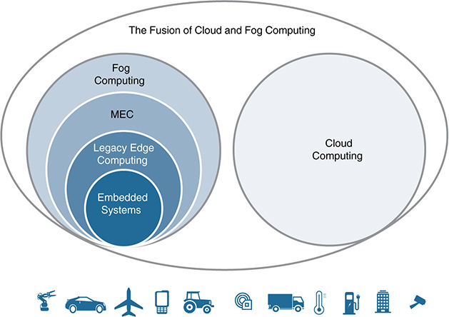
Figure 6-21 Terminology and Reach of Different Technologies That Offer Computing Capabilities in the IoT Space
Embedded systems were used for many different applications even decades before the IoT revolution arose. An embedded system represents a set of computing resources that were designed to perform a specific (dedicated) function. As the name indicates, these computing resources are built into or embedded in devices (things) that require such functionality. Embedded systems are common in the consumer electronics space (printers, video game consoles, telephones, cameras, and so on), as well as in a vast list of applications in the areas of manufacturing, oil and gas, transportation, cities, and so on.
Embedded systems are a subset of a larger set that encompasses different forms of data processing at the edge of the network. This superset is usually referred to as edge computing. It gathers a large number of uses that enable computing functions near the source of the data. The term near can mean as close as inside the data source itself (embedded), or it can mean detached from it, as long as it remains in proximity. This second case usually means that the edge computer can communicate with the data source by means of short-range radio, or it might be directly plugged into it. An advantage of edge computing is that it can be used to process data arriving from different entities (things), and those entities can be using different communication protocols, security means (for example, encryption), data formats, and so on. Embedded systems are purpose built, so they have a dedicated and well-defined function. In this sense, whereas embedded systems certainly offer edge computing capabilities, their functionality is typically limited to their intended use. On the contrary, an edge computer can be a general-purpose appliance configured to connect either with a single device (thing) to perform a very specific task, or to communicate with multiple things as an aggregation point and perform multiple tasks simultaneously.
The term legacy in the edge computing set shown in Figure 6-21 is important. The evolution of mobile networks and smartphones is rapidly changing the concept of what an edge computer is. Modern smartphones and tablets definitively fall into the category of edge computers. In many cases, they are way more powerful than a broad spectrum of the edge computing platforms in industry (for example, many manufacturing plants still run Windows stations from the 1990s).
The next set on the left side of Figure 6-21 precisely expands the reach of edge computing, to include both legacy systems and the next generation of mobile endpoints. One initiative that stands out in this field is being carried out by an Industry Specification Group under ETSI, called MEC. Originally, the acronym MEC stood for Mobile Edge Computing, but later the ETSI group was renamed to Multi-access Edge Computing. MEC tackles the convergence of IT and telecom networking, with special focus on next-generation mobile base stations under the 3rd Generation Partnership Project (3GPP). Among the central aspects addressed by MEC are the following:
■ Open radio access network (RAN): In the model being developed by MEC, operators will leverage edge computing and open their RANs in such a way that third-party companies can deploy applications to create innovative services targeting mobile subscribers. MEC currently targets the enterprise and vertical sectors.
■ User equipment (UE) mobility: The goal is to allow an operator’s mobile networks to support continuity of user services under a variety of mobility patterns. This can include mobility of applications (for example, with runtime environments supported by VMs) as well as mobility of application-specific information (for example, user-related data). This is a complex problem because many of the scenarios envisioned by MEC are characterized by high bandwidth and ultra-low latency requirements.
■ Virtualization platform: The goal is to allow operators to run both their own applications and third-party applications on their mobile network edge. The mobile network edge infrastructure will be virtualized and can be seen as an NFV-PoP. This means that it could be implemented as an NFVI managed by NFV MANO. MEC acknowledges the synergies between MEC and NFV, as well as the fact that operators will find it advantageous to reuse their NFVI and NFV MANO platforms to the largest extent possible, thereby capitalizing on their investments. In any case, MEC also clarifies that its architecture could be implemented without NFV, so it is moving forward with its specification program without strong dependencies on NFV.
Overall, the third set on the left side of Figure 6-21 represents a superset of edge computing systems. Note that the use of MEC in Figure 6-21 is to denote that MEC is expanding the reach of traditional edge computing to incorporate the next generation of mobile devices and networks. It is also worth noting that the scope of MEC is limited to the network edge. Fog computing has a larger charter because its focus is on the continuum between things and the cloud. In this sense, MEC and next-generation edge computing represent a subset of the subjects covered by fog computing.
To better explain the reach of fog computing and why it is effectively a superset of edge computing, let us describe one of the use cases detailed in the “OpenFog Reference Architecture for Fog Computing,” a document released by the OpenFog consortium in February 2017. Figure 6-22 shows an example of a smart traffic system supported by fog, including multiple interactions between various fog and cloud domains. In the future, autonomous cars will be common, and each vehicle will produce a large amount of data. For instance, the cameras in the car, smart positioning systems, light detection sensors, radars, and so on will perfectly generate several terabytes of data per day. More importantly, a considerable part of the data is critical for safety reasons and requires processing and decision making at timescales and with a level of reliability that cloud-only models cannot offer. Fog nodes need to be used in smart autonomous transportation, and they will interact with fog nodes in other vehicles, with the surrounding infrastructure, with mobile phones, and so on. Security and data privacy considerations in this environment merit a separate book and thus are beyond the scope of this chapter. Herein, the goal is to expose why fog computing goes far beyond edge computing, regardless of whether the nodes are static or mobile.

Figure 6-22 OpenFog Transportation: Smart Car and Traffic Control System (from the Reference Architecture Document Published by the OpenFog Consortium in February 2017)
To this end, Figure 6-22 shows a number of interactions between different elements in a smart traffic system, including the following entities:
■ Fog nodes located in different places (inside vehicles, on the roadside, in hierarchical arrangements in the continuum between edge and cloud, and so on).
■ These fog nodes will support different types of communications, including vehicle-to-vehicle (V2V), vehicle-to-infrastructure (V2I), vehicle-to-pedestrian (V2P), and infrastructure-to-infrastructure (I2I).
■ Fog domains.
■ These domains can include fog networks owned and operated by different organizations (for example, in the form of a federation). These multidomain networks will be part of a highly regulated system in which both private and public fog networks will coexist to provide services to devices, pedestrians, and vehicles.
■ Multitenancy across fog nodes is another way to manage administrative domains. This capability is especially relevant for city departments and municipalities because they can consolidate multiple fog networks to reduce not only the amount of equipment that needs to be installed, secured, and maintained but also the power consumed.
■ Several cloud domains.
■ Both private and public clouds can be potentially used by any fog node or endpoint device.
■ Element management systems (EMS).
■ Service providers (SP).
■ Metropolitan traffic services.
■ Multiple car manufacturers.
■ Multiple types of sensors and control and actuation elements. These include roadside sensors, on-vehicle sensors, sensors carried by pedestrians, and so on. These sensors provide and consume data so that the various actors in the smart traffic system can perform their corresponding functions (pedestrians can be safer, controllers can regulate the traffic lights according to the traffic flow, vehicles can drive autonomously and safely, and so on). A smart traffic system can also manage other elements in urban spaces, such as digital signs, cameras, and gates.
One of the key differentiations between edge and fog computing is the hierarchical nature of fog, which is clearly visible in Figure 6-22. The applications in the vehicles can connect to different fog nodes in the infrastructure (for example, on the roadside), which can then connect to other fog nodes in the hierarchy to provide many services, such as congestion avoidance and roadwork, monitoring public events affecting traffic circulation, rerouting traffic to reduce the level of pollution in certain areas, optimizing routes for emergency vehicles, and more.
Three different types of fog nodes are essential in a smart traffic system:
■ Fog computing nodes inside vehicles: A vehicle, whether autonomous or driven by a human, might contain one or several fog nodes inside, which will communicate with other mobile fog nodes (V2V), the infrastructure (V2I), pedestrians (V2P), and other elements (such as sensors in the vehicle [V2x]). These nodes are capable of performing a number of tasks autonomously, even in the absence of connectivity with other fog nodes nearby or in the cloud. Different functions might be provided by different fog nodes, depending on their criticality. For instance, infotainment services will remain physically separated from other life-threatening functions, such as autonomous driving and collision avoidance functions, advanced driver assistance systems (ADAS), and navigation systems. Technologies such as cellular (for example, LTE, 5G, and C-V2X), Wi-Fi, and dedicated short-range communications (DSRC) can be used to support secure V2x communications.
■ Fog computing nodes in the infrastructure: Roadside fog nodes represent the entry point and the first level of the fog hierarchy. These fog nodes gather data from other devices, such as roadside cameras, vehicles, and fog nodes at higher levels in the hierarchy. They perform localized computation, including data analysis and decision making that results in specific actions, such as alerting vehicles about an accident ahead or suggesting a detour. Data produced and aggregated at this first level can be sent up to fog nodes located higher in the hierarchy (for example, for further analysis and distribution to different parties). Each level in the hierarchy provides additional capabilities that do not need to be supplied by lower levels in the hierarchy. For instance, higher levels typically have more processing power and storage capacity, and thus can process data received from a pool of fog nodes from lower levels. Higher-level fog nodes can also provide functions that lower-level nodes do not need, such as data mashups. Mashups could enable more elaborated analytics, by bringing together a selection of data received from various other sources (including data from fog nodes higher in the hierarchy) and combining the data in ways that can be consumed by business support systems. In addition, part of the data can be shared with other fog nodes at the same level, enabling east-west communications (for example, to extend the reach and geographical footprint of a fog domain).
■ Fog computing nodes as part of traffic control systems: For safety reasons, many countries manage their traffic light systems in isolation (that is, the network that supports the traffic lights remains physically separated from any other network). Countries have strong regulations related to this topic, but the advent of smart cities is opening the door for smarter and connected traffic control systems. This enables a minimal level of connectivity with external systems, although it is limited to only a few authorized entities and the data that can be exchanged is highly controlled and restricted. For instance, a trusted fog node controlling a set of traffic lights in an area could receive data from the metropolitan traffic services or from specific infrastructure fog nodes in the hierarchy. The fog node would then make decisions based on the data received (for example, to provide a green wave for an emergency vehicle, such as a police car, or increase the duration of the green light by x number of seconds to speed up the traffic flow in a given direction).
The example of a smart traffic system highlights the potential of fog computing. It shows a complex IoT system combining multiple actors, with the capacity to produce and exchange massive amounts of data. It also outlines the reach of fog computing and demarcates the boundaries between edge computing and a full-fledged fog computing system. This should illustrate why fog computing represents the superset at the top on the left side of Figure 6-21.
Fog and cloud are clearly different, although they are highly complementary. The mutual benefits are evident—so evident that the most plausible step in the evolution is their fusion. The term fusion is used here in the sense that computing nodes in the fog and the cloud can be exposed to end users as a single, unified, and continuous resource fabric. Recall that fog represents a continuum between things and the cloud, but currently, any IoT service demanding computing resources in both the fog and the cloud requires the use of separate management systems. This entails duplicating not only management functions and systems required for managing the lifecycle of the different components of an IoT service (for example, the infrastructure, applications, data distribution system, and VNFs), but also the tasks for enforcing forwarding policies, security, and so on. For instance, deploying a smart traffic system such as the one in Figure 6-22 would require instantiating and configuring multiple applications in virtualized environments across fog networks and clouds. Instead of needing to use independent orchestration systems to automate service deployments in fog and cloud, orchestration tasks will likely be unified. The same will happen for service assurance and security, including integrated policy definition, enforcement, and lifecycle management. In this scenario, ETSI’s NFV MANO stands out among all other possible candidates. As described in Chapter 8, NFV MANO can be used beyond the networking domain. It has the potential to become the standardized orchestration system for IoT, thereby enabling the fusion of fog and cloud management systems.
Figure 6-23 illustrates the chronological evolution that we are witnessing in the marketplace, starting from appliance-based networking (on the left) up to the expected fusion of fog and cloud (on the right). Cloud-ready functions are applications that have been ported from the desktop to the cloud and are now ready to offer premium experience when running on the cloud. Cloud-native functions, on the other hand, are applications that were devised and developed to run natively on the cloud. In this case, applications are usually decomposed into simpler, smaller, and independent functions called microservices, which can work in concert to build an application. This has changed the traditional method of building monolithic applications, in which new releases typically demanded the upgrade of the entire application. The application needed to be stopped, updated, and then relaunched, obviously impacting its operation. Cloud-native applications, on the other hand, consist of a set of microservices that can be upgraded individually and relaunched almost instantaneously because they can be supported by lightweight virtualized environments such as Docker containers.
Likewise, fog-ready functions are applications that were ported to run in fog nodes. For instance, power control tools for monitoring elements in an electrical dashboard were typically built as embedded systems—that is, the controller was one more physical element in the electrical dashboard. With the advent of fog computing and the deployment of general-purpose fog nodes capable of consolidating multiple applications closer to the things, several companies that formerly provided the controllers as physical appliances are now offering virtualized versions of them. These were tailored to run in fog nodes and, hence, are fog ready. As mentioned previously, the next chapter in the evolution of fog and cloud is quite likely the fusion of their management planes. As with the case in cloud, developers will gradually decompose their applications into microservices that are crafted to run efficiently in the virtualization layer offered by the cloud-to-thing continuum.

As discussed earlier in this chapter, SDX and NFV are instrumental technologies for the expansion and evolution of cloud computing, and they are expected to have a similar role in the case of fog computing. Many service providers, enterprises, and system integrators are heavily betting on NFV. This will drive the need for a unified service management framework that can orchestrate not only VNFs, but also IoT services that involve the fog domain. The OpenFog consortium has not yet specified the orchestration system for the fog continuum (at least, not at the time of this writing). The capabilities offered by NFV MANO are highly complementary to the architecture proposed by the OpenFog consortium; therefore, NFV MANO is a clear candidate to enable unified orchestration and management across fog networks and distributed back ends. Figure 6-24 outlines how these two architectures can come together and complement each other in practice.
The left side of Figure 6-24 represents the physical separation between fog and data centers hosting not only the NFV MANO components, but also the virtual functions (VF) and virtual infrastructure (VI) supporting the IoT service back ends. The OpenFog reference architecture is split into four blocks: (1) the “things” located southbound of the fog nodes, (2) a fog node in the cloud-to-thing continuum (the figure zooms in and shows the main components and layers that constitute a fog node), (3) a set of traversal functions capable of managing different aspects of an IoT service, and (4) the user interface (UI) and other management services offered to the administrators in a multitenant IoT environment.
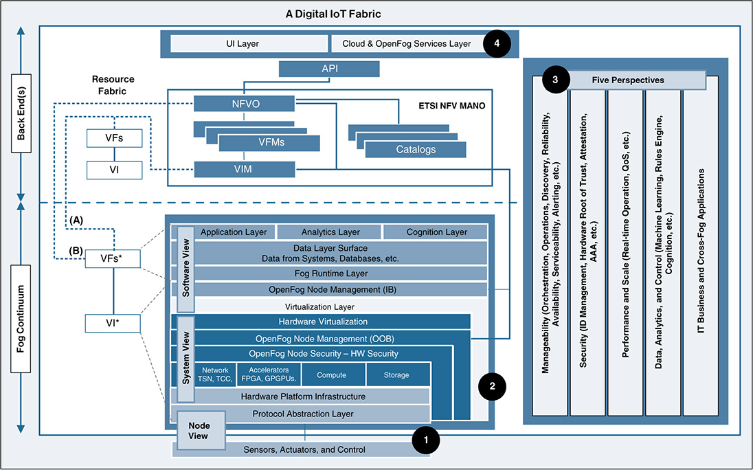
Figure 6-24 Converged NFV MANO and OpenFog Architectures (from the IEEE Article “Toward a Converged OpenFog and ETSI MANO Architecture,” by M. Yannuzzi et al.)
The traversal capabilities, denoted as perspectives and the node, system, and software views in Figure 6-24 adhere to the capabilities and terms defined in the reference architecture document published by the OpenFog Consortium. These perspectives enable manageability, security, performance and scaling mechanisms, data analysis and control, and business intelligence (BI) and cross-fog applications. Note that a converged architecture avoids duplicity of roles and functionality at the fog and back-end levels.
An adequate combination of role-based access control (RBAC) and the northbound API of the NFV orchestrator (NFVO) can enable multitenancy. In this case, NFV MANO can orchestrate and manage virtual functions (instances) in both the back end and the fog domain for different clients. These instances are denoted in the figure as VFs, and VFs*, respectively. Note that, instead of talking about VNFs, we generalize this concept and use the term VFs; a service chain in IoT consists of virtual functions that go beyond network-centric functionality. Currently, NFV MANO implementations are based on a three-tier model: the NFVO, a set of virtual network function managers (VNFM), and a virtual infrastructure manager (VIM). As in the case of the VFs, instead of talking about VNFMs, we use the term virtual function managers (VFM). The left side of Figure 6-24 shows how NFV MANO can now instantiate VFs in the virtual infrastructure offered by the back end (VI), as well as in the one offered by fog (VI*).
The instantiation of VFs* in the fog domain requires interfacing with the OpenFog architecture. These interactions are enabled through the two interfaces shown on the right side of block 2 in Figure 6-24 (between MANO and the OpenFog node management layers). OpenFog defines two different OpenFog node management layers, allowing out-of-band (OOB) management mechanisms and in-band (IB) ones. OOB mechanisms refer to manageability functions that do not run on the host operating system. These generally encompass management mechanisms that can survive all power states, such as the ones defined by the Intelligent Platform Management Interface (IPMI) specification. IB mechanisms refer to manageability functions that are visible to the software and firmware running on a fog node. For instance, the process to spin up a virtual machine (VM) or a Linux container (LXC) in a fog node from the back end requires IB management.
The process for commanding the instantiation of a virtual function (VF*) in the fog virtual infrastructure (VI*) can be accomplished in different ways. Figure 6-24 illustrates two possible schemes, A and B. Scheme A is based on the traditional interactions of NFVO, VFM, and VIM, which means that the fog node becomes a computing element managed by the VIM. This requires a client that can run as an agent in the fog node. Although there are no technical barriers for implementing scheme A, commercial support might be an issue because existing VIMs (such as OpenStack or VMware) might not be willing to extend their support beyond the walls of a data center. Scheme B, on the other hand, is a VIM-less scenario, which might offer more flexibility in the fog domain because the fog node can be registered and managed directly by the NFVO. The functionality offered by the VFM and VIM can now be distributed, embedded, and autonomously managed by the fog nodes, while still adhering to the NFV MANO design principles. Clearly, this scheme does not require commercial extensions to existing VIMs.
Overall, a converged OpenFog and NFV MANO architecture can elastically scale and manage the lifecycle of physical and virtual entities and services across back ends running in public or private data centers, networks, and fog nodes. It is worth noting that the industry’s move toward converged architectures is much bigger than fog and NFV. Figure 6-25 shows this trend, with SDX, cloud, NFV, IoT, fog, and 5G technologies progressively coming together. SDX and NFV will be instrumental to that end. For instance, challenges such as the revenue gap in Figure 6-13 have been instrumental in the choices made related to virtual RANs (vRAN) and the slicing methods prosed by the 3GPP program for 5G. Another clear example is that today it is hard to conceive technologies like NFV or fog without a back-end platform running on the cloud (whether private, public, or hybrid).

Figure 6-26 illustrates this convergence and the evolution of industry in this direction. The figure shows four different scenarios, progressively integrating technologies and transitioning to a converged model (from left to right).
■ Scenario A: Figure 6-26 (a) represents the typical scenario of today. The IoT use case corresponds to a smart power control system. These systems usually offer bidirectional communications, enabling real-time monitoring in the upstream direction and control and actuation in the opposite direction. More specifically, power monitoring elements can be integrated into electrical dashboards, which can be remotely monitored by a user. The monitoring elements send their data to the local controller (usually a proprietary power controller that is integrated as another physical element in the electrical dashboard). The data collected and processed by the controller is securely sent to an application running in the cloud that can aggregate and analyze data from a large number of remote locations. This application is typically proprietary as well and is provided by the same company that supplies the monitoring elements, the controllers, and the protections and circuit breakers. The application running in the cloud usually offers an API to expose data that can be consumed by a UI managed by the user. This API also supports control and actuation methods, enabling a user to perform actions remotely, such as selectively switching power off or on along different lines. In this scenario, the network is implemented using PNFs (physical appliances). For example, the power controller can be connected via Ethernet to a switch in the local network, which then connects to a DMZ and, from there, to a border router providing WAN connectivity (MPLS, in this case). This could be the setup for a building whose power consumption is being remotely monitored and controlled. As mentioned previously, the application hosted in the cloud can control hundreds of buildings. The technologies involved in this scenario fall under the IoT and cloud sets in Figure 6-25.
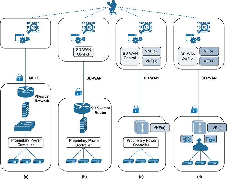
Figure 6-26 From Legacy Setups to More Advanced IoT Scenarios Integrating SDX, NFV, Fog, Cloud, and 5G
■ Scenario B: This scenario implements exactly the same use case as in the previous scenario, but with a different setup. It introduces SD-WAN technology, simplifying WAN management considerably. The external connectivity is optimized by a centralized SD-WAN controller running in the cloud. The SD-WAN controller not only optimizes connectivity across MPLS, Internet, and LTE links, but it also simplifies the internal installation of networking equipment by introducing SDN-based switches. The SDN controllers of the SDN switches are installed locally (on-premises), and the applications controlling these latter can be provided by the centralized SDN-WAN controller running in the cloud. In this scenario, the technologies involved fall under IoT, cloud, and SDX sets in Figure 6-25.
■ Scenario C: This scenario introduces NFV to the setup discussed in scenario B. The advantage in this case is that the network setup for remote locations (for example, in the building) becomes much simpler. Most of the PNFs that were formerly implemented locally have moved upstream and can now run on the other end of the WAN (for example, in an NFV-PoP) in the form of VNFs (for example, provided as SaaS or PaaS). Expensive MPLS connections can be replaced by some form of FTTx and can be bundled together, enabling traffic control and load balancing, commanded by the SD-WAN controller, and enforced by the VNFs in the NFV-PoP. Note that the SD-WAN controller does not need to reside in the NFV-PoP; it can remain hosted in the cloud. In this scenario, the technologies involved fall under IoT, cloud, SDX, and NFV sets in Figure 6-25.
■ Scenario D: Previous scenarios progressively simplified the network setup and management for the user, but the IoT-related components remained unchanged. This scenario introduces fog computing and combines it with the setup described in Scenario C. In this case, the power controller is virtualized and runs in the fog node shown at the bottom of the figure. This new setup has several advantages. First, it can considerably reduce the number of controllers needed because a single controller can aggregate data from multiple electrical dashboards in a more centralized, hierarchical way. Second, the controllers can become more sophisticated and locally implement part of the functionality provided by the proprietary application running in the cloud. This approach allows the application to remain operative even if the remote site loses backhaul connectivity to the NFV-PoP. Third, the data managed by the power controller can be combined with other sources of data, mashed up, to produce new business outcomes (for example, enabled through more data and additional granularity in decision-making processes). Fourth, the fog node is not constrained to solely implement power control; it can run other types of applications concurrently (for example, to monitor and control elevators, HVAC systems, applications for optimizing lighting, digital signals, and so on). This scenario covers IoT, cloud, SDX, NFV, and fog in Figure 6-25. In the near future, 5G will come into play. For example, SD-WAN systems will incorporate 5G communications, virtualized services will leverage NFV and MANO, and common combinations will involve fog for some use cases and longer-range 5G communications that bypass edge computing. A key observation related to orchestration is that NFV MANO is gradually being adopted to orchestrate the deployment and automate the configuration of services involving customer premises equipment (CPE). By extending its reach beyond the networking domain, NFV MANO can perfectly orchestrate fog nodes—and IoT services in general—in a similar way as it does today with CPEs.
Summary
If MANO implementations continue to evolve and become the orchestration system of choice for NFV deployments, the orchestration systems for fog computing eventually will need to either interoperate with MANO or build upon on it. Development teams working on next-generation orchestration systems for fog computing should follow the advances made in MANO, and consider both the pros and cons and the risk of going in a direction that is not aligned with future NFV architectures. The progress made in SDX technologies is also key. Although controller platforms such as OpenDaylight cannot completely offer the functionality required by many fog platforms (at least, with their current releases), they provide a good reference and knowledge base because they are well advanced in many features that will be required in fog. A clear example is the MD-SAL, and the way to create new plug-ins based on formal data modeling languages, such as YANG. Indeed, YANG is a promising candidate for the data modeling language of choice in IoT and future fog-enabled platforms. Chapter 8 delves into these aspects in much more detail.
References
“Difference Between AD-SAL and MD-SAL,” available from SDN Tutorials: http://sdntutorials.com/difference-between-ad-sal-and-md-sal/
The Official ODL Site: https://www.opendaylight.org
“OpenFog Reference Architecture for Fog Computing,” the OpenFog Consortium Architecture Working Group. February, 2017
Yannuzzi, Marcelo and Rik Irons-Mclean, et al., “Toward a Converged OpenFog and ETSI MANO Architecture,” IEEE Fog World Congress, October/November, 2017.