
Chapter 15. Industrial Environments: Oil and Gas
Topics covered in this chapter include
■ The IoT and Secure Automation Opportunity in Oil and Gas
■ The Downstream and Processing Environments
■ Oil and Gas Security and Automation Use Cases: Equipment Health Monitoring and Engineering Access
The oil and gas (or petroleum) industry is not a modern phenomenon. Historical records thousands of years old describe the early use of oil derivatives. The earliest recorded oil wells were drilled in China around 350 A.D.; the first basic refinery was built in Russia in 1745, with oil sands being mined in France at the same time; and the first modern refinery was built in Romania in 1856. However, not until the early 20th century, when the internal combustion engine was invented, did petroleum become such an important factor in politics, society, and technology and evolve into the economic staple of today.
Oil and gas is considered the largest industry in the world in terms of dollar value. Despite the recent uncertainty in the market and the lowered price per barrel of oil, the industry is still extremely successful and continues to experience overall growth. The raw materials produced by the industry create multiple products, including chemicals, pharmaceuticals, solvents, plastics, fertilizers, and—the largest products by volume—fuel oil and petrol (gasoline). With such a broad range of products that are essential to daily life, the oil and gas industry is critical to many industries—and increasingly important to many economies around the world.
Oil demand and oil consumption have both risen steadily over the last few decades, and today more than four billion metric tons of oil are produced globally each year. Oil accounts for a major percentage of energy consumption regionally: 53 percent in the Middle East, 44 percent for South America, 41 percent for Africa, 40 percent for North America, and 32 percent for Europe and Asia. The long-term outlook for the oil industry appears robust, with projections in global demand increasing until at least 2035, with transportation and heavy industries the highest-consuming sectors. Daily global oil consumption is expected to grow from the 89 million barrels logged in 2012 to a projected 109 million barrels in 2035.
However, over the past decade, the base price of a barrel of oil has dropped significantly. Today it sits at less than a third of the value from ten years ago (see Figure 15-1). This means the industry must continue to explore and invest in technologies and business practices that will enable them to become increasingly efficient—and increasingly competitive—to manage barrel price fluctuations and industry trends.

Not only is the oil and gas industry critical from an economic perspective, but there is heightened focus on the reliability of the sector because of its potentially catastrophic impact on both the environment and human life. In 2014, the U.S. Occupational Safety and Health Administration reported that the oil and gas fatality rate was seven times higher than the rate for all U.S. industries combined. From a human perspective, multiple challenges are involved, including vehicle accidents, operational machinery incidents, explosions and fires, falls, confined spaces, chemical exposures, and work in remote locations. All of these have an impact on human safety. At the same time, several highly visible incidents have caused environmental damage, including the Exxon-Valdez spill in 1989 and the Deepwater Horizon Macondo incident in 2010.
Operating during this new norm of lower oil prices and heightened safety and environmental awareness not only poses challenges for inefficient oil and gas companies, but also drives even the efficient ones to find new and consistent methods to preserve their profitability, compliance, and reputation. The oil and gas industry has long been an adopter of innovation and new technology to drive new business models and profit. Technology is a key mechanism in enabling the next wave of business transformation in the oil and gas sector. A 2015 Deloitte whitepaper argues that digitization through IoT promises to help petroleum organizations meet these challenges head on as part of their key focus to accomplish the following goals:
■ Improve reliability and manage risk: Minimizing the risks to health, safety, and the environment by reducing disruptions
■ Optimize operations: Increasing productivity and optimizing the supply chain through the cost and capital efficiency of business operations
■ Create new value: Exploring new sources of revenue and competitive advantage that drive business transformation
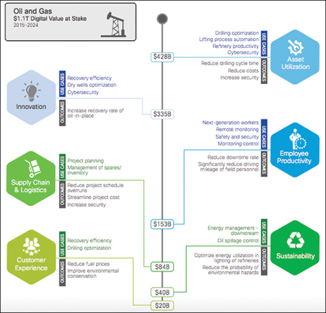
The potential value of IoT for oil and gas companies does not come through directly managing their assets, supply chains, or customer relationships. IoT provides new information about these parts of the business, delivering a new level of value (see Figure 15-2). Companies can leverage this information to gain greater insight and make better decisions.
Gavin Rennick, President of Software Solutions at Schlumberger, describes the changing oil and gas customer perspective: “Most companies in oil and gas today [are] focused on how to not just survive, but how to thrive in the new environment industry finds itself in. They are looking at how to create value for themselves and their customers, and how to differentiate themselves with their products. Much of their focus is around efficiency and effectiveness and how they deliver that across their enterprise.”
The oil and gas sector has always welcomed technology, but the aforementioned lower oil prices and competitive pressures have ushered in a need to accelerate the deployment of new technologies. The promise of reducing costs, replacing manpower through automation, and providing better business insight through Big Data and analytics has prompted the deployment of relatively immature IoT solutions in a critical industry as businesses place higher priority on optimization and operational efficiency.
With the introduction of new technologies, the companies have an increased attack surface, both cyber and physical, that attackers will seek to exploit. A robust, responsive, and comprehensive security approach is needed to ensure the safety and reliability of this critical industry while, at the same time, meeting new business objectives. This includes best practices in terms of how operations are managed with safety, reliability, and high availability in mind, along with protection from any potential cyber or physical security attacks.
This chapter explores the oil and gas industry in greater depth, discusses the changes digitization through IoT brings, shows how to adopt an appropriate security posture using advanced technologies, and explores the automation needed for technology to be responsive to business needs. The chapter concludes with a use case that applies to all areas of the oil and gas value chain; we walk through a practical deployment to better visualize the concepts.
The 2016–2017 Ernst and Young Global Information Security Survey shows that oil and gas companies are making good progress in the way they sense and resist security threats and attacks. The survey also highlights that technology is being deployed at an increasing pace as the industry prepares for significant change. However, the survey results demonstrate that improvement is still needed in the area of security, particularly in terms of improved resilience and automated response. Other improvements needed include the capability to counter and respond to cybersecurity incidents and the capability to rapidly restore and maintain any compromised operations. This fits with the focus of this book: Companies want to quickly and safely deploy new technology and use cases; rapidly identify, understand, and respond to security threats; and provide contextual information to return operations to an expected state as quickly as possible.
Industry Overview
The oil and gas value chain starts with exploration to discover resources and then moves through development, production, processing, transportation/storage, refining, and marketing/retail of hydrocarbons. In industry terms, it follows five distinct areas of exploring, developing, refining, transporting, and marketing of oil and gas products, although these are typically divided into the three segments of upstream, midstream, and downstream (see Figure 15-3).

Upstream includes the initial exploration, evaluation and appraisal, development, and production of sites. This is referred to as exploration and production (E&P). These activities take place both on- and offshore. Upstream focuses on finding wells, determining how deeply or widely to drill, and determining how to construct and operate wells to achieve the best return on investment. This includes both conventional and unconventional oil production. Conventional production includes crude oil and natural gas and its condensates. Unconventional production consists of a wider variety of liquid sources, including oil sands, extra heavy oil, gas to liquids, and other liquids. In unconventional production, petroleum is obtained or produced by means other than traditional well extraction.
Upstream activities include surveying and searching for underground or underwater oil and gas sources, conducting drilling activities, and developing and operating wells (if the wells are deemed economically viable).
Midstream activities can include elements of both the upstream and downstream areas. They primarily focus on the gathering, transport, and storage of hydrocarbons via pipelines, tankers, tank farms, and terminals that provide links between production and processing facilities, and then the processing facilities and the end customer. Crude oil is transported from the midstream to the downstream refinery for processing into the final product.
Midstream activities also include the processing of natural gas. Although some of the needed processing occurs as field processing near the production source, the complete processing of gas takes place at a processing plant or facility, which it typically reaches from the gathering pipeline network. For wholesale markets, natural gas must first be purified with natural gas liquids (NGL) such as butane, propane, ethane, and pentanes before it is transported via pipeline or turned into liquid natural gas (LNG) and shipped. The gas can be used in real time or stored. The NGLs then are leveraged downstream for petrochemical or liquid fuels, or are turned into final products at the refinery.
Downstream activities are concerned with the final processing and delivery of product to wholesale, retail, or direct industrial customers. A refinery treats crude oil and NGL, and then converts them into consumer and industrial products through separation, conversion, and purification. Modern refinery and petrochemical technology can transform crude materials into thousands of useful products, including gasoline, kerosene, diesel, lubricants, coke, and asphalt.
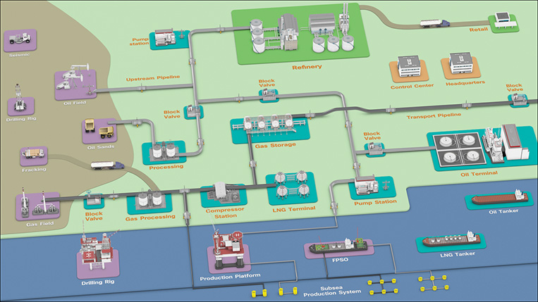
Figure 15-4 shows a simplified visual overview of the value chain.
The IoT and Secure Automation Opportunity in Oil and Gas
Historically, the traditional response to a market downturn has been to cut costs by reducing employees and capital expenses. The initial response to the current changing market conditions followed a similar approach, but many oil and gas companies are tackling uncertain market conditions with a fresh mind-set as they seek to gain competitive advantage in a market where lower oil prices are the new norm:
■ Oil and gas companies are focusing on getting more out of what they already have.
■ IoT technology has matured and deployments carry less risk.
■ IoT provides new opportunities to improve efficiencies and operational optimizations of existing and new projects.
■ IT and OT teams are working more closely together to realize business value.
■ Speed of decision and speed of response are critical.
However, delivering on these potential advantages is possible only if key business and operational processes are automated. In a 2015 Cisco Survey, more than half of the oil and gas companies that responded believed IoT could automate between 25 and 50 percent of their manual processes. At the same time, almost all respondents cited security as a barrier to deploying technology. To achieve their aims, organizations need to better understand where IoT technology can best help automate and secure their business digitization, and help them gain a slice of the potential value at stake.
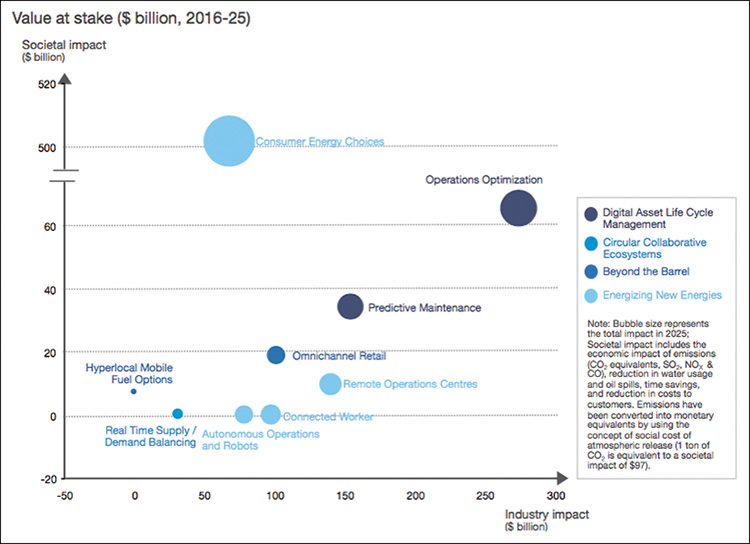
A 2017 World Economic Forum whitepaper estimated that digitization in the oil and gas industry could unlock approximately $1.6 trillion of value for the industry, its customers, and wider society (see Figure 15-5). This could potentially increase to $2.5 trillion if operational and organizational constraints were relaxed to allow additional “futuristic” technologies. Key areas, and the biggest opportunity for the industry where secure IoT automation can play a part, are operations optimization and predictive maintenance.
The whitepaper also found that digitalization has the potential to create around $1 trillion of value for oil and gas companies, with $580 billion to $600 billion in upstream companies, $100 billion to midstream companies, and $260 billion to $275 billion to downstream companies. Oil and gas organizations have a clear opportunity to invest in IoT.
A 2016 Accenture Digital Trends study found that the top areas of focus for oil and gas companies during the next three to five years include IoT and Big Data and analytics (see Figure 15-6). The same study also found that projects often separate IoT and Big Data, and only 13 percent use the insights to shape their approach toward the market and their competitors. This discrepancy highlights the fact that digitization strategies are not always embracing, and technology is often applied piecemeal.

The Accenture study uncovered key themes and initiatives that fit in with the foundations of this book. This includes a “new era of automation” and advanced analytics and modeling, together delivering the following:
■ Autonomous operations
■ Remote operations
■ Predictive maintenance
■ Operations optimization
■ Cognitive computing
The new era of automation has the potential to transform how oil and gas companies operate. Combining these technologies provides a real opportunity to improve real-time processes, such as choosing where to drill, how best to optimize production, and how to provide predictive maintenance of assets.
This is further backed by a 2016 Bain Consulting report (see Figure 15-7) that found digital technology automation had the capability to add value for all areas of the oil and gas value chain. This was particularly true for production and refining and processing, through remote operations and operational efficiencies.

In working with two of the world’s oil and gas majors, Cisco has documented almost 100 use cases for IoT and digitization. Table 15-1 shows some examples.
Table 15-1 Examples of IoT and Digitization Use Cases
Upstream |
Midstream |
Downstream |
|---|---|---|
Distributed Acoustic sensing |
Flow Profiling |
Gas Monitoring |
Distributed Continuous 4D Seismic |
Oil and Gas Leak Detection |
Life Safety and Emergency Response |
Downhole Measurements |
Pipeline Encroachment and Tampering Protection |
Equipment Health Monitoring |
Oil Rig and Field Sensors |
Pipeline Optimization |
Valve Status and Lineups |
Equipment Health Monitoring |
Equipment Health Monitoring |
Tank Level Monitoring |
Remote Expert |
Remote Expert |
WF and Turnarounds Optimization |
Video Analytics |
Physical Perimeter Monitoring |
|
Remote Expert |
||
Video Analytics |
In an offshore project in Asia, Cisco worked with an oil and gas major to deploy an advanced wellhead automation use case to detect for water ingress into the well. Using a manual method, the typical deployment time per well was 7 to 10 days. Through automation, when the physical equipment was deployed at the well, the same use case could be deployed (with all applications, virtual machines, data pipeline, communications, and so on) in around 7 minutes. This provides a major opportunity for streamlining operations and increasing safety.
As the chapter progresses, we explore in greater detail how IoT and digitization can help address these new and growing solutions to drive business optimization, safety, and profitability. Importantly, we also address what this means to an industry as technology is adopted. Rennick states, “Today, we believe there are around 8 billion and, within a decade, about a trillion connected devices. These devices are producing an enormous amount of data, so data becomes central—the quality of data, how the data is managed, the security of data. How to extract real value, real insight from that data is really important.”
The Upstream Environment
The following sections discuss the upstream environment in more detail and describe the impact of IoT, digitization, and security.
Overview, Technologies, and Architectures
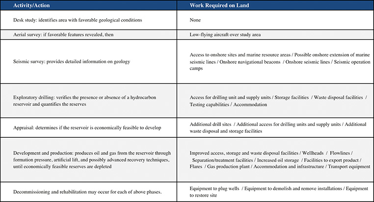
Oil and gas are discovered, developed, and produced upstream. When a company has obtained the necessary permit, exploration teams gather subsurface data to determine the best sites to drill one or more initial exploration or test wells. A seismic survey is the most common assessment method; it identifies geological structures through the differing reflective properties of soundwaves’ subsurface.
The exploration wells are then drilled based on survey findings. On land, a well pad is constructed at the chosen site to support drilling equipment and other services. Over water, a variety of self-contained mobile offshore drilling units handle the drilling, depending on the depth of the water and conditions.
If initial drilling shows that oil and gas are present in commercially viable amounts, additional appraisal wells are drilled to assess the discovery. Experts estimate the extent and volume of the find. If the find is positive, the field becomes a candidate for development.
Additional development or production wells are drilled, with a small reservoir potentially being developed with multiple wells. The number of wells can range from a handful for a smaller reservoir, into the hundreds for a large one. As sites become occupied for longer, additional services such as accommodations and water supplies are established. The activities conclude when the control valve “Christmas tree” makes the well ready for production.
Most wells are initially free flowing because of their own underground pressure; however, some might not be, and most will vary over time. To optimize the flow, each well can be stimulated using gas, steam, or water to achieve a certain pressure, optimize production rates, and increase the overall potential of the well. As fluids are produced, they are sent to a local production facility that separates oil, gas, and water.
This process continues for the life of the well or reservoir—usually when it is no longer economically viable to produce instead of when all reserves are exhausted. Figure 15-8 shows an overview of the entire process.
During the last decade, the focus on nonconventional oil and gas production has increased. This normally refers to methods such as hydraulic fracturing (fracking) or oil sands mining. Fracking is used when underground fields contain large quantities of oil or gas but have a poor flow rate due to low permeability, such as shale or tight sands. Fracking stimulates wells drilled into these areas so that they can be developed when other methods would not be financially viable.
Fracking occurs after a well has been drilled, when the casing is complete. The casing is perforated at specific target areas so that injected fracturing fluid (typically, a mixture of water, proppants [including sand], and chemicals) move through the perforations into the target zones that contain oil or gas. Eventually, the target area will not be able to absorb fluid as quickly as it is injected, and this will cause the formation to fracture. Injection then stops and the fracturing fluids flow back to the surface, with the injected proppants holding open the fractures.
Oil sands are loose sand deposits that contain a type of petroleum called bitumen. Oil sands, also called tar or bituminous sands, are found all over the world. Oil sands are surface mined and the products are produced in three steps. Bitumen is extracted from the sand and any water or solids are removed. Heavy bitumen is then processed, or upgraded, to a lighter intermediate crude product. The crude is then refined into final products.
To get the most out of the upstream environment, communication and solution technologies are needed, especially as we look at real-time processes, visualization, and actuation. Historically, satellite was a prevalent communications technology, but this has progressed to alternative wireless and wired technologies for communications infrastructure. Additional complementary technologies include video surveillance, collaboration and conferencing, accommodation and employee welfare, and operational technologies such as asset management and predictive maintenance. With IoT, this extends to advanced digitization technologies such as Big Data and analytics, machine learning, and Artificial Intelligence. Figure 15-9 shows an example architecture for the onshore development and production environment; Figure 15-10 illustrates an example production platform.
The connected oilfield aims to improve recovery, accelerate production, reduce downtime, improve operating efficiency, and reduce drilling costs. IoT technologies are enabling oil and gas companies to run operations remotely and minimize safety risks, provide real-time processing and analytics directly in the field, enable a more productive mobile workforce, and create smarter wells.


Digitization and New Business Needs
The lowered oil price per barrel has seen less of a focus in upstream exploration. McKinsey & Co. believes the biggest opportunity for improving efficiency and profit lies in production. McKinsey argues that the biggest enabler in this area is automation. Organizations can use automation to maximize asset and well integrity (optimizing production without impacting employee health and safety or the environment), increase field recovery, improve product throughput, and minimize downtime.
Even small improvements in production efficiency can translate into financial gains, with additional throughput from the same assets equaling more revenue. Combining this with reduced nonoperational time by increasing the reliability of equipment will also cut operational costs and extend the life of assets.
McKinsey sees remote automation (semi- or fully automated) operations as an enabler for these upstream needs:
■ Delivering more complex operations with increasing volume, in hostile locations, where logistics must be optimized for efficiency and where profitability is a challenge due to declining production or a need for efficient maintenance schedules.
■ Ensuring compliance for health, safety, security, and environmental incidents. Automating production control, monitoring the condition of the equipment, and using predictive shutdown systems can all be enabled through automated IoT to prevent or mitigate events, especially in geographically dispersed remote locations.
■ Addressing the skill and experience gap. Retention and recruitment are unlikely to fill the current gap. IoT technologies can automate many routine analysis and decision-support processes, as well as fully automate them, where possible. A Rockwell Automation study found that 21 percent of industrial automation workers (2.5 million workers) will retire in the next eight years in the United States. Seventy-five percent of employers say new skills in the industry will be required during the next two years.
Automation is needed to address the changing competitive landscape, where speed and agility are essential for operators and contractors to deliver new services, optimize existing services efficiently, and capture some of the value at stake.
Preventive automated maintenance is a key example in which both equipment providers and users of equipment are combining condition- and performance-monitoring technology to improve asset productivity and reliability. The same automated approach can be implemented throughout the upstream environment, including topside, subsea, and down hole.
In addition to asset improvements, IoT can address human efficiency and productivity. Deloitte estimates that the upstream industry loses $8 billion per year in nonproductive time, with engineers spending around 70 percent of their time searching for and manipulating the data produced from sensors and equipment. Better-generated data and advanced analytics can deliver the right information to streamline upstream operations.
However, Deloitte also recognizes that the human factor is a bottleneck in efficiently leveraging the data, and that automation is a key enabler to optimize what is produced. The data must be analyzed if it is to improve existing operations and identify new areas with potential performance improvement. However, this cannot be achieved by people alone. Deloitte also believes that digitized automation will have the greatest impact on production and predicts that IoT applications could reduce production and lift costs by more than $500 million for a large integrated oil and gas company.
Price Waterhouse Cooper also provides a consistent narrative for IoT and digitization in oil and gas upstream, with applications the main enabler for smarter and safer operations that are geared to real-time decision making, and managed by a leaner staff. PWC sees the following key trends:
■ Digitization driving both the short- and long-term transformation opportunities, with profitability driven through intelligent maintenance, workflow automation, better workforce utilization, and increased standardization of process designs and equipment
■ More automation, leading to better health, safety, and environmental performance, and averting or minimizing work errors and other accidents
Challenges
Although IoT promises many benefits in the upstream segment of oil and gas, certain challenges still need to be addressed:
■ Security: Technology is evolving, more devices are connecting to the network, attackers are using increasingly sophisticated methods, and OT and IT technologies are converging. Security is needed to protect assets, people, and intellectual property from cyber and physical threats. With the associated critical infrastructure, and an increasing number of devices and systems connected through IoT, security becomes not only a responsibility for IT or OT, but also a critical requirement that spans the entire organization.
■ Scale and environment: Being able to deploy new and advanced use cases, particularly over highly distributed environments, is a challenge. Some of the environments are incredibly harsh or difficult to reach. Automation is a key requirement to enable scale, but historically, there have been no standardized methods to addresses scale issues in a consistent way throughout the IoT system. As real-time data points and data generation continue to grow, better tools for deploying, configuring, and managing large data are needed.
■ Skill sets: Worker age and skill sets have changed. As younger workers with more of an IT-based skill set join the workforce, being able to train and provide remote expertise and consultation to new workers is essential. Being able to automate key complex tasks in a simple way is key to address missing skill sets as experienced workers retire.
■ IT and OT integration: Cultural, philosophical, and organizational differences still exist between IT and OT teams. This raises the challenge of ownership of IoT technologies and operational activities. Architectures that have traditionally been followed, such as the Purdue Model of Control and IEC 62443, do not easily lend themselves to some IoT use cases, such as direct sensor connectivity in operations to the enterprise or cloud. Careful consideration of how a single technology can be leveraged holistically in an organization needs to be addressed.
■ Legacy device integration: Industrial environments are typically a mix of legacy and modern devices. Both need to be included in an IoT solution.
The Midstream Environment
The following sections discuss the midstream environment in more detail and describe the impact of IoT, digitization, and security.
Overview, Technologies, and Architectures
Transmission pipelines are a key transport mechanism and operate continuously 24/7/365, outside of scheduled maintenance windows. Pipelines provide an efficient, safe, and cost-effective way to transport processed or unprocessed oil, gas, and raw materials and products in both onshore and offshore environments. Safety and efficiency are critical; if any issues occur, service must be restored as quickly as possible to meet environmental, safety, quality, and compliance requirements.
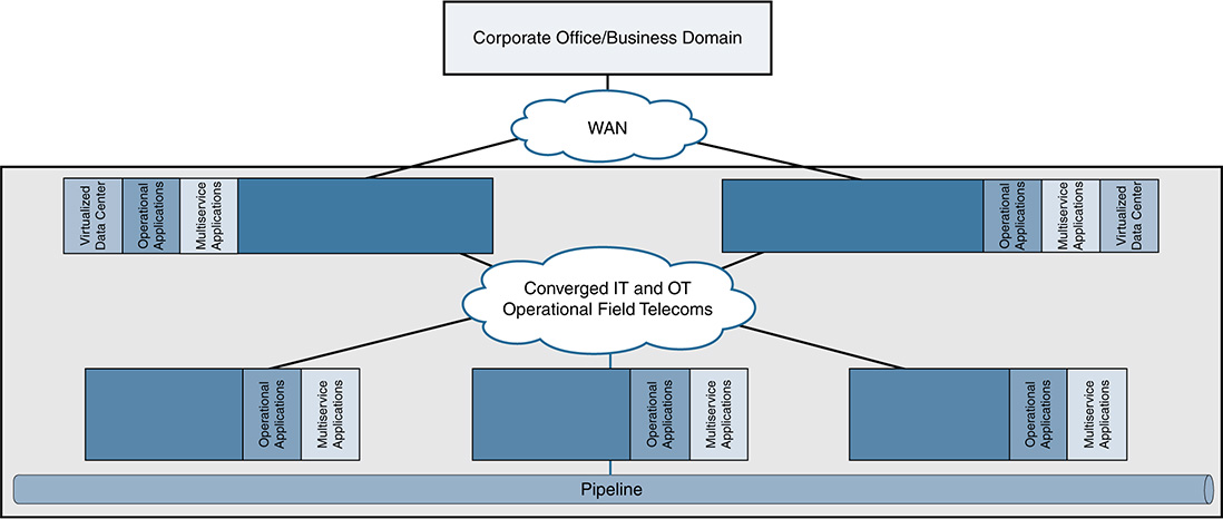
Oil and gas pipelines consist of process, safety, and energy management functions that are geographically spread along the pipeline for a set of stations (see Figure 15-11). In addition, multiservice applications support operations, such as voice, CCTV, emergency announcements, and mobility services. Stations vary in size and function but typically include large compressor or pump stations, midsize metering stations, pipeline inspection gauge (PIG) terminal stations, and smaller block valve stations.
Pipeline management applications manage the entire pipeline system (see Figure 15-12). Each process and application can be linked with the corresponding processes and applications at other stations and at the control centers through a communications infrastructure. The process must be conducted in a reliable and efficient way, avoiding communications outages and data losses. The control centers that house the pipeline management applications should also be securely connected to the enterprise through a WAN to allow users to improve operational processes, streamline business planning, and optimize energy consumption.

Pipeline management applications provide operators with the following:
■ Real-time/near-real-time control and supervision of operations along the pipeline through a SCADA system based in one or more control centers
■ Accurate measurement through the pipeline for product flow, volume, and levels, ensuring accurate product accounting
■ Capability to detect and locate leakage along the pipeline (including time, volumes, and location distances)
■ Safe operations through instrumentation and safety systems
■ Energy management to visualize, manage, and optimize energy consumption in pipeline stations
■ Security systems for personnel, the environment, and the physical infrastructure, using video surveillance and access control technologies
The pipeline management systems feed information to enterprise applications for optimization, billing, and other services.
Pipeline management is challenging, with pipelines often running over large geographical distances, through harsh environments, and with limited communications and power infrastructure available. In addition, pipelines must comply with stringent environmental regulations and operate as safely as possible. They also must address growing cyber and physical security threats.
However, key pipeline requirements have not changed. Pipeline integrity, safety, security, and reliability are fundamental aspects that help operators meet increasingly demanding delivery schedules and optimize operational efficiency and costs.
The industry is changing, of course, and IoT technology is driving many new use cases, including advanced leak detection, distributed acoustic optical sensing, tamper and theft detection, mobile workforce, and advanced preventive maintenance. The capability to connect to operational equipment, instrumentation, and sensors in a secure way can provide real-time operational data that allows incidents or failures to be quickly identified and addressed (or prevented altogether) and services to be optimized.
Regardless of the use cases, any pipeline management system must provide the following:
■ High availability: Redundancy and reliability mechanisms at the physical, data, and network layers, including robust differentiated QoS and device-level redundancy
■ Multilevel security: Protection against both physical and cyber attacks, and nonintentional security threats
■ Multiservice support: Operational and nonoperational applications coexisting on a communications network, with mechanisms to ensure that the right applications operate in the right way at the right time
■ Open standards: Based on IP, with the capability to transparently integrate and transport traditional or older serial protocols, and ensure interoperability between current and future applications
Architectures typically follow the Purdue Model of Control or IEC 62443. Zoning and segmentation handle different operational layers, and a strict divide exists between operations and the enterprise.
Digitization and New Business Needs
Globally, there has been a business shift in terms of what is being transported. The new model provides variable volumes and product grades from multiple locations to end users in place of the traditional fixed supply/demand areas and limited grades.
When combining this new business model with the operational challenges associated with the existing aging infrastructure (often with manual monitoring and control and legacy equipment), both challenges and opportunities arise.
Deloitte believes that the traditional trend will do little to enhance the operational efficiency, reliability, or safety for pipeline operators. The old approach of adding more of the same traditional hardware and software and following the traditional statistical and historical rules-based approaches is unhelpful. A new approach is needed that leverages IoT digital technologies (sensors, hardware, and software). This data-centric focus, created through generating new data such as machine and sensor data, weather and geolocation data, and machine log data, will accomplish two main aims:
■ Enhance safety through better visibility into operational activities provided by new data sources
■ Facilitate the connection and combination of industrywide data to make better decisions and improve operational performance
The key is not only to provide secure IoT technologies to connect and transport data, but also to combine this with analytics and automate the end-to-end processes. A Price Waterhouse Cooper study found that only a few midstream organizations are currently capturing meaningful value from their digital investments. This will increase in the coming years, particularly through new advances in integrating field data, compliance data, and maintenance data to enable advanced analytics and achieve simulations that help meet efficiency and safety goals.
Use cases include the following:
■ Field collaboration and mobility
■ Remote expert
■ Real-time analytics and edge processing
■ Inspection vehicle mobility
■ Predictive intrusion, leak, environmental detection
■ Personnel tracking in large plants and along pipeline
Many process control vendors in the industry share this perspective as they seek to transform their own business models and competitive offerings through increased opportunity to connect, measure, and analyze increasing data sets to then make better decisions faster. This process would include operational decisions and business decisions more closely connecting the OT and IT parts of an organization. A Schneider Electric whitepaper on IoT found that IoT benefits these areas in pipeline management:
■ Environmental monitoring: SCADA-based pipeline management applications can leverage new IoT data to monitor and improve environmental protection by measuring areas such as air or water quality in stations and strategic locations.
■ Infrastructure management: Better visibility is offered into the monitoring and controlling operations along the pipeline, including stations, pipeline pressures, pipeline terminals, and tank farms.
■ Enhanced operations controllers: This helps to bridge the skills gap as a highly skilled but aging workforce retires and new, typically younger workers replace them. IoT data can provide better and more meaningful information to operator screens, can provide more information linking multiple systems for wider analysis, and can help automate some of the processes that previously needed a high skill level.
■ Energy management: Measuring and billing applications linked to additional IoT data give pipeline operators and energy managers access to precise cost data that instantly monitors energy usage costs. These enable operators and managers to make the best decisions on optimizing energy efficiency. As a result, profitability improves and environmental gas emissions decrease.
Schneider Electric sees three large benefits of IoT for pipelines:
■ Enterprisewide approach: IoT has the capability to more closely link IT and OT teams and technologies to provide greater business control by bringing together automation systems with enterprise planning, scheduling, and product lifecycle systems. Pipeline-management systems can reap more of these benefits as automation systems are more tightly integrated with the overall enterprise applications.
■ Automated predictive maintenance: Through a “smart infrastructure plan” that focuses on an automated predictive maintenance approach, pipeline operators can substantially improve the performance of equipment, reduce energy costs, and operate a more environmentally friendly business.
■ Speed to deploy new services: The convergence of energy, automation, and software is increasing, allowing a fast way to deliver more advanced technology and innovation at every level of the IoT system.
Ultimately, Schneider Electric sees IoT as “enabling the common goal of making the pipeline industry more connected, safe, reliable, efficient and sustainable for today and for future generations.”
Challenges
Although IoT promises many benefits in the midstream segment of oil and gas, it faces the same challenges as the upstream segment:
■ Security: Technology is evolving, more devices are connecting to the network, attackers are using increasingly sophisticated methods, and OT and IT technologies are converging. Security is needed to protect assets, people, and intellectual property from cyber and physical threats. With the critical infrastructure of pipelines and an increasing number of devices and systems connected through IoT, security becomes not only a responsibility for IT or OT, but also a critical requirement that spans the entire organization.
■ Scale: Being able to deploy new and advanced use cases, particularly over highly distributed environments such as pipelines, is a challenge. Some of the environments are incredibly harsh or difficult to reach. Automation is a key requirement to enable scale, but historically, there have been no standardized methods to addresses scale issues in a consistent way throughout the IoT system. As real-time data points and data generation continue to grow, better tools for deploying, configuring, and managing large data are needed.
■ Skill sets: Worker age and skill sets have changed. As younger workers with more of an IT-based skill set join the workforce, being able to train and provide remote expertise and consultation to new workers is essential. Being able to automate key complex tasks in a simple way is key to address missing skill sets as experienced workers retire.
■ IT and OT integration: Cultural, philosophical, and organizational differences still exist between IT and OT teams. This raises the challenge of ownership of IoT technologies and operational activities. Architectures that have traditionally been followed, such as the Purdue Model of Control and IEC 62443, do not easily lend themselves to some IoT use cases, such as direct sensor connectivity in operations to the enterprise or cloud. Careful consideration of how a single technology can be leveraged holistically in an organization needs to be addressed.
■ Legacy device integration: Industrial environments are typically a mix of legacy and modern devices. Both need to be included in an IoT solution where technology does not change at the rapid pace of IT. Once deployed, operational devices can have a lifespan of more than 10 years.
The Downstream and Processing Environments
The following sections discuss the downstream environment in more detail, and describe the impact of IoT and digitization, and security.
Overview, Technologies, and Architectures
Refineries and processing facilities process raw or semiprocessed materials and create final products.
Refineries and large processing plants are typically sprawling complexes with many piping systems interconnecting the various processing and chemical units. Many large storage tanks might also be located around the facility. A plant can cover multiple acres, and many of the buildings and processing units could be multiple stories high. The processing units and piping networks have a very high metallic element, often with large distances between buildings or treatment areas. Plants are also not static environments; regular upgrades to equipment take place to ensure efficient operations. In addition, some areas are potentially highly explosive because of the gases produced during the chemical processes. Challenges can include potentially deadly gas leaks or corrosion due to steam and cooling water around the plant.
Products are produced on a continuous basis. The plant must have the capability to continuously control and monitor operations via systems that collect data on pressure, temperature, vibration, and flow, among other parameters.
A plant might host hundreds of workers, including company employees, contractors, and external company support staff. People and automation systems are responsible for ensuring that individual parts and the entire process are working correctly, monitoring the efficiency of the process and optimizing or redesigning where necessary, and maintaining ensure equipment. With the size of the facility and the need to transport raw materials or finished products, multiple vehicle types move through the environment, including cars, trucks, lorries, tankers, and trains.
To ensure that systems, processes, and people are operating efficiently and safely, control systems (typically, a distributed control system [DCS]), management systems, and safety systems are deployed. To ensure that these systems can operate in a timely manner across the refinery or processing facility, a comprehensive and reliable communications system must be implemented.
Figure 15-13 shows a typical plant architecture. It usually follows a recognized industrial architecture, such as IEC 62443, and is segmented into different zones (including safety, process control, energy management, and multiservice applications to support operational activities such as mobility, CCTV, and voice). Pervasive wireless, both the 802.11 spectrum and the 802.15.4 spectrum, is often deployed to support use cases and the connection of sensor networks.
Communications must support process control applications, from instruments or sensors to the control room applications. A wide range of devices operate within the plant, including programmable logic controllers (PLC), controllers, intelligent electronics devices (IED), human machine interfaces (HMI), operator or engineering workstations, servers, printers, wireless devices, and instrumentation and sensors. Technologies are often categorized as operational (those directly involved with supporting operations such as the process control or safety systems) and multiservice applications (either those that support operations, such as video surveillance, or those that are more concerned with business applications, such as voice and corporate data).
Unlike a SCADA system, which is based on a central command-and-control model, a typical plant deploys a distributed control system that divides control tasks into multiple distributed systems (see Figure 15-14). If part of the system fails, other parts continue to operate independently. This characteristic makes this type of model suitable for highly interconnected local plants such as process facilities, refineries, and chemical plants.


With increased requirements for physical safety and security, employee mobility, access to data, and collaboration with site-based or remote expertise, multiservice use cases are increasing in the facility environment:
■ Employee mobility
■ Physical security and access control
■ Voice and video
■ Data access
■ Location tracking (people, assets, vehicles)
IoT promises to deliver improvements in the refining and processing space through a number of use cases:
■ Operational efficiency of equipment via real-time data collection, analysis, and local closed loop control, plus historical trends and optimization
■ Predictive and prescriptive maintenance to prevent downtime
■ Health and safety through real-time people tracking, mobile and fixed gas detection, and video analytics
■ People productivity via mobility technologies, video for remote support and training, anywhere access to tools, and location tracking and route optimization
■ Security and compliance via real-time data collection, status alerts, and video checking
■ Planned downtime reduction through the use of wireless and mobility technologies to speed up plant turnaround
Digitization and New Business Needs
The refining industry is mature and has many years of experience in process control and automation. However, the industry has had few recent technology innovations. Operators of refineries and large processing plants have focused on operational efficiency improvements and ensuring the continuation of production, with shutdowns (scheduled turnaround or unplanned) impacting revenue as output is reduced. The second area operators focus on is improving maintenance. A Deloitte study estimated that unscheduled shutdowns reduced industry output by 5 percent, or $20 billion, annually; nonoptimized maintenance resulted in shutdowns that cost $60 billion per year.
Maintenance typically occurs via a scheduled turnaround in which the plant, or sections of it, are shut down to allow for inspection, fixes, and upgrades. Maintenance generally occurs on a scheduled pretimed basis, even if maintenance is not needed. Advances in IoT technologies now allow for smart devices, pervasive wireless networks, standards-based interoperable communications, and the use of analytics to move away from planned maintenance to condition-based predictive or prescriptive maintenance.
In addition to downtime, production losses (such as incorrect feedstock mixes) have a major impact on profitability. Accenture estimates that 80 percent of losses are preventable and believe that IoT technologies can significantly reduce losses through the integration of real-time information and automated decisions.
Automation is seen as critical in minimizing the amount of human involvement and intervention, engineering time, and time spent on maintenance activities. Automation can reduce all three.
Price Waterhouse Cooper sees additional opportunities for IoT technologies to improve refinery operations through remote (both human-controlled and automated) operations. Smart sensors and pervasive communication networks connecting every piece of equipment can be leveraged for whole-process analytics and simulations, as well as fully automated control loops.
Challenges
The same challenges exist in the downstream space as in the midstream and upstream spaces (security, scale, skill sets, and IT and OT integration). These are further amplified in an industry that is already running in a highly efficient manner. Any opportunities to reduce downtime and improve efficiency should be considered.
IoT technologies are increasingly critical to the daily operation of the industry. As new use cases and business needs drive greater dependence on providing highly available and secure connectivity to people, smart devices and sensors, equipment and machinery, and often geographically separated assets, both the operational and enterprise sides of the organization are coming to rely on digital technologies. The value these technologies provide is becoming integral to new projects in oil and gas, and some of the main benefits are already being seen in implementations where automation is prevalent:
■ Optimized resource (equipment, machines, people) utilization to increase efficiency
■ Increased visibility into machines and equipment to identify potential failures and operational support information through real-time data
■ Reduced costs and impact to the environment through remote operations across large geographic regions
■ Centralized policy and security management to enable a uniform approach to meeting and enforcing regulatory and compliance goals
■ Flexibility, scalability, and mobility of IoT systems to increase business agility in response to changing market demands and to increase competitive ability through speed
■ Automated safety and security measures to reduce critical event response times
The challenge for many of these areas is not technology, but people and processes. The technology exists to automate and enhance through IoT, but only when processes are safely and securely automated will oil and gas companies be able to fully start to take advantage of their benefits. This applies to operational efficiency, remote operations, reduced downtime, and safe operations.
It is essential to understand that a single technology cannot enable the industry to meet these requirements. Only a properly architected, secure integration of IoT technologies and applications into a coherent IoT platform, combined with a philosophical or cultural change, will reduce cost, improve efficiencies, keep workers safe, and continue to drive innovation.
The correct use of IoT and digitization platforms to automate and secure oil and gas use cases can have real benefits. Rennick says: “We have reduced the time it takes to plan and engineer a well in half. We also found that 90 percent of the tasks petrophysicists and geologists were conducting could be automated, making them more efficient and able to focus on high-value tasks. We are also seeing a 30 percent improvement in service reliability; availability increased 15 percent; and there are many other real impact examples.”
Security in Oil and Gas
Because of the critical nature of the industry, oil and gas systems and infrastructure should be one of the most secure sectors, from both physical and cyber perspectives. In reality, however, this is often not the case. ABI Research found that, from early security threat examples such as Night Dragon and Shamoon, oil and gas companies have been continual victims of attacks. Many of these attacks have caused significant damage to the companies’ finances and reputations. Regardless of this damage, the industry is slow in deploying appropriate infrastructure measures to prevent or mitigate such attacks. This is despite a prediction that the industry will spend $1.87 billion on cybersecurity in 2018. A Deloitte report in 2016 found the energy industry to be the second-most-attacked industry via cyber threats: Nearly 75 percent of U.S. oil and gas companies were subject to at least one cyber incident in the past year. In 2014, more than 300 Norwegian oil and gas companies suffered from cyber attacks.
As the industry continues to evolve, automation, digitization, and IoT communications are being rapidly integrated into the operational ecosystem (operators, vendors, services companies, niche partners, and so on). Ensuring that security is linked directly back to the industry’s top imperatives of safety, high reliability, and generation of new value is essential, to give it the best chance of success.
A 2015 study by DNV GL found that only 40 percent of oil and gas companies have a plan to address security from digitization. The report lists the top ten security vulnerabilities facing customers, against the backdrop of an ever-increasing sharing of data between operations and the enterprise:
■ Lack of cybersecurity awareness and training among employees
■ Remote work during operations and maintenance
■ Use of standard IT products with known vulnerabilities in the production environment
■ A limited cybersecurity culture among vendors, suppliers, and contractors
■ Insufficient separation of data networks
■ Use of mobile devices and storage units, including smartphones
■ Data networks between on- and offshore facilities
■ Insufficient physical security of data rooms, cabinets, and so on
■ Vulnerable software
■ Outdated and aging control systems in facilities
In addition, the predicted three main factors that will influence security for the future are predicted to be operational cost savings, the long lifetime (10 to 25 years) of equipment that is deployed, and IoT and digitization. The opportunity to deliver new use cases, new value, and competitive advantage is also one of the greatest threats to security and needs to be addressed.
Historically, oil and gas industrial control systems have been isolated from the outside world and have often used proprietary technologies and communications. Security has typically been addressed through a security-by-obscurity approach, with digital and logical security not a primary concern. With the modernization of control systems and the inclusion of consumer-off-the-shelf (COTS) products that leverage standardized protocols and are connected to public networks, the process domain needs a comprehensive security framework and architecture with appropriate technologies to enforce security in a consistent way. The use of IoT/IIoT, more IT-centric products and solutions, and increased connectivity to the enterprise and outside world means that new cyber attacks from both inside and outside the operational environment are inevitable.
Security incidents should also not be seen as purely external or malicious. As identified in the previous reports and whitepapers, the human factor plays a huge part in security. Incidents can typically be categorized as either malicious or accidental:
■ Malicious acts are deliberate attempts to impact a service or to cause malfunction or harm. An example is a disgruntled employee planning to intentionally affect a process by loading a virus onto a server used within the operational control domain, or someone taking control of a process by spoofing a human machine interface (HMI).
■ Accidental incidents are more prevalent in technology environments. This can involve, for example, accidentally misconfiguring a command on networking equipment or process controllers, or connecting a network cable to an incorrect port. Accidental human error poses the same threat to the safety of people, processes, and the environment.
Any method (such as automation) that can reduce, mitigate, or eliminate potential challenges caused by the human factor should be seen as a key strategic imperative to address security, safety, and compliance.
In the oil and gas industry, many risk outcomes need to be considered as a result of a malicious or accidental attack:
■ Plant, pipeline, or equipment shutdown
■ Production shutdown
■ Unacceptable product quality
■ Disruption to site utilities
■ Undetected spills or leaks
■ Safety systems and measures bypassed, resulting in injuries, deaths, or environmental impact
All of these impact profitability and reputation, which are key areas to protect in the changing industry.
Best practices for oil and gas recommend following an architectural approach to securing the operational domain, the enterprise domain, and any links between and outside connections. This also includes the people and systems in each area. The most widely used architectural approach in oil and gas is IEC 62443. With the changing needs driven by IoT and digitization, newer approaches (such as those recommended by the IIC and OpenFog consortium, and the Open Process Automation standard) are becoming more important because their scope is much broader than IEC 62443. Chapter 4, “IoT and Security Standards and Best Practices,” covers all of these standards.
As outlined in Chapter 5, “Current IoT Architecture Design and Challenges,” IT and OT teams in industrial environments can have different perspectives and mind-sets, even though they might have common goals of securing an organization’s systems. A brief summary of the key points surrounding security architectures and approaches follows (also see Chapter 5):
■ Increasing convergence is occurring between IT and OT teams and tools.
■ IT-centric technologies are being increasingly leveraged to secure operational systems.
■ OT and IT solutions cannot simply be deployed interchangeably; the architecture and requirements are crucial to ensuring that use case requirements are met.
■ IT and OT teams often have different priorities and skill sets.
■ Research argues that a shared set of standards, platforms, and architectures across IT and OT will reduce risk and cost.
■ A common platform architecture and approach should be developed to address existing and new use cases. This provides the strongest approach to security.
■ Whenever possible, approaches to security, architecture, and technology should be based on open interoperable standards.
The approach to security in the oil and gas environment has improved dramatically over the past few years. However, the industry has inherited some challenges:
■ The operational environment has policies, procedures, and culture that cannot adequately deal with the growing security risk.
■ Control systems networks were not designed adequately. Security is often a bolt-on and no defense in depth is provided.
■ The myth of control systems and networks being unconnected to the outside world and enterprise systems when, in reality, connectivity exists, even if through a firewall.
■ The traditional approach to operational system design comes from an engineering perspective, not a secure IT perspective.
■ Systems have been designed and installed with insufficient security controls, and these will remain in place.
■ Security is often decoupled from the compliance process.
The listed challenges are not criticisms of the operational environment; they are merely common problems stemming from the fact that systems are designed to last over long periods of time and typically are created with an engineering process as a priority. In addition, many security threats are unknown or have not been considered.
Certain key standards and guidelines apply to oil and gas, including the IEC 62443 Industrial Control System Standard; the API 1164 Pipeline SCADA Security Standard; NIST 800-82, Guide to Industrial Control System Security; IEC 27019, Security Management for Process Control; NIST Process Control Security Requirements Forum (PCSRF); and NERC-CIP (when interfacing with the power grid). Other related guidelines include remote station best practices (electronic and physical perimeters) and Chemical Facility Anti-Terrorism Standards (CFATS). The typical approach is to build security architectures that follow the recommendations outlined in the Purdue Model of Control (see Figure 15-15), with a tiered and securely segmented model.
In oil and gas, the approach would consist of the following components:
■ Internet/external domain (Level 5/L5): Provides connectivity to the organization’s applications and data to external parties, via the Internet, or to private supplier networks and clouds.
■ Enterprise/business domain (Level 4/L4): The enterprise or business network that typically provides nonindustrial applications and end user connectivity. It is usually managed by centralized IT.
■ Industrial DMZ (Level 3.5/L3.5): The ingress and egress point for all connectivity between the operational and enterprise domains. No direct connectivity exists between L4 and L3, and communications typically gain access via a proxy or jump server. This layer typically hosts shadow/ghost servers, with operational information pushed from the operational domain so that enterprise users can access it. Although this is not an official layer of the model, it has become a standard component because of the need to securely exchange data between operations and enterprise environments.
■ Operations (Level 3/L3): System-level control and monitoring applications, historians, production scheduling, and asset-management systems.
■ Supervisory control (Level 2/L2): Applications and functions associated with the cell/area zone supervision and operation, including HMIs.
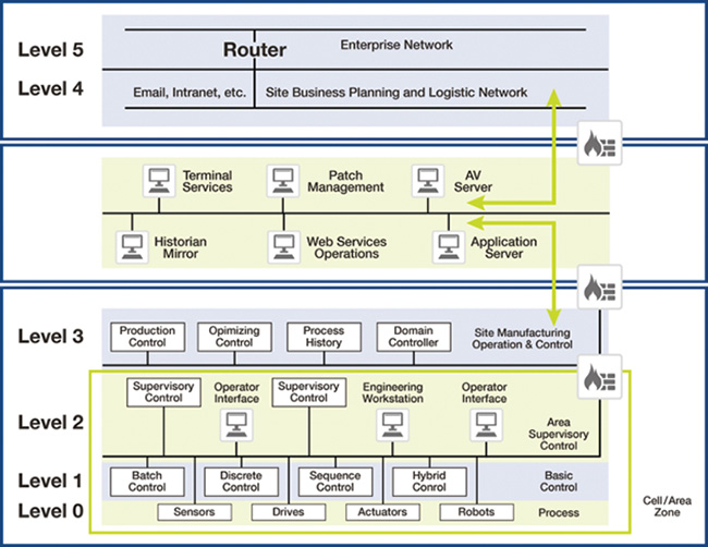
■ Local control (Level 1/L1): Controllers that direct and manipulate the process by interfacing with the plant equipment. Historically, the controller is a programmable logic controller (PLC).
■ Level 0/L0: Field instrumentation and devices that perform functions of the IACS, such as driving a motor, measuring variables, and setting an output. These functions can range from very simple (temperature) to complex (a moving robot).
■ Safety: Critical control systems designed to protect the process.
A very strong divide exists between the operational and enterprise environments of the same organization. This often means duplication of technologies, systems, and services (see Figure 15-16).
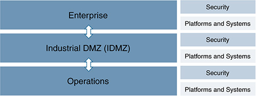
As discussed throughout this book, organizations are seeing value in securing the data exchange between these historically isolated domains. The convergence of IT and OT is a common challenge most industrial environments face when they adopt IoT architectures; it drives both OT and IT to have communication interfaces that allow mutual access and the exchange of information between systems. It has also given rise to the need for the L3.5 IDMZ as mentioned earlier, which is gaining more importance due to the increasing need to exchange data between, and provide secure access between, the operational and enterprise domains. We even see this pushed into lower levels of the operational domain, and L2.5 IDMZ protection zones are now being introduced to provide similar functionality.
In oil and gas, the enterprise network and the operational process control domain (PCD) need to exchange services and data. Systems located in the industrial DMZ, such as a shadow historian, bring all the data together for company personnel, exposing near-real-time and historical information to the enterprise for better business decision making.
Industrial security standards (including IEC-62443) recommend strict separation between the PCD (Levels 1–3) and the enterprise/business domain and above (Levels 4–5). No direct communications are allowed between the enterprise and the PCD. The IDMZ provides a point of access and control for provisioning and exchanging data between these two entities. The IDMZ architecture provides termination points for the enterprise and the PCD by hosting various servers, applications, and security policies to broker and police communications between the two domains.
The IDMZ should ensure that no direct communications occur between the enterprise and the PCD unless explicitly allowed, and also should provide secure communication methods between the enterprise and the PCN using “mirrored” or replicated servers and applications. The IDMZ should be the single point of entry for secure remote access services from the external networks into the PCD. It also should be the single point of control for enterprise services in the PCD (including the operating system patch server, the antivirus server, and domain controllers).
Segmentation to enforce zones and boundaries that are identified through a risk assessment should be extended into the IDMZ architecture. Security technologies that provide boundary services for the IDMZ should deny any service unless explicitly configured through the use of a conduit. All services must be identified and rules must be put in place to explicitly permit communications through a firewall.
General principles apply to all levels of an oil and gas solution:
■ Architectures must be able to securely restrict and isolate services, to preserve the integrity of the traffic.
■ Intentional or accidental cross-pollination of traffic between untrusted entities must be restricted.
■ Securing a perimeter for operational services (between different services and systems, or from non-operational traffic) must be achieved utilizing isolation techniques at the various levels of the infrastructure.
■ Security zones can be segmented using physical (different devices, cables, or lambdas) or logical separation (VLAN, VRF, resource virtualization, and so on).
■ Traffic movement between zones must be strictly enforced via conduits.
■ These techniques are not just restricted to traditional networking platforms; they must be followed throughout the architecture into the computing and storage areas.
■ Access to any part of the system must be defined and controlled.
A well-designed solution infrastructure that follows industry-standard guidelines should be able to support physical, logical, or mixed application segmentation implementations, depending on the end user philosophy. The key requirement is that solutions interoperate inside and among architectural tiers/levels. Creating a secure level is pointless if devices at the field level have been compromised and are sending inaccurate or corrupted information. Security spans all levels of the architecture and must address the risk to the organization.
Regardless of which applicable standard is chosen for the oil and gas system, some fundamental security considerations need to deployed as simply and consistently as possible. (Each standard touches on these, to some degree.) These include fundamental security mechanisms:
■ Discovery and inventory
■ Risk analysis
■ Reference architecture and security philosophy
■ System access control
■ Identification, authentication, authorization, and accounting
■ Use control
■ System hardening
■ System and device integrity, media
■ Resource availability
■ Data confidentiality
■ Restricted data flow and infrastructure design
■ Zoning and segmentation
■ Conduits to provide interzone traffic flows
■ Industrial DMZ, enterprise and operational segmentation, operational support applications (voice, video, mobility, and so on)
■ System operational management, monitoring, and maintenance
■ Business continuity/disaster recovery
■ Physical and environmental security
Enhanced security requirements follow:
■ Managed security services
■ Organization of information security
■ Compliance
■ Business continuity
■ Active threat defense
■ Intrusion detection and prevention
■ Security behavioral analytics
■ Penetration testing (one-off service/event)
■ Shared operations and handoff points
■ Nontraditional architectures
■ IIoT and cloud
■ Open process automation
■ Human resources/personnel security
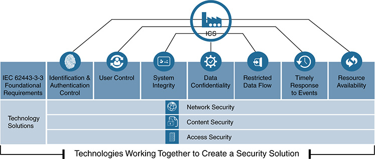
From a practicality perspective, and to address standardization and consistency in the approach to security, it is essential to use an end-to-end approach with technologies that are designed to be deployed and operated together, while minimizing risk and operational complexities (see Figure 15-17).
The 2016–2017 Global Information Security Survey from Ernst and Young shows that oil and gas companies are making progress in how they detect and deal with attacks and threats. However, the study also indicates a need for improved resilience and better preparation to respond and react to potential security incidents. Also needed is the capability to restore safe and reliable operations as quickly as possible (through autonomous or semiautonomous contextual automation and deployment/responses).
Although security threats are increasing, security budgets are staying relatively static. Security departments tend to focus on purchasing the latest security tools instead of investigating and evaluating the underlying business behaviors and root causes to better deploy holistic systems to addresses security within their finite budgets. In the oil and gas sector, security budget constraints are often further stretched by the different roles and responsibilities of the OT and IT teams. OT security often falls outside the duties of a Chief Information Security Officer or Chief Information Officer, and this can lead to duplication of security spending and resource efforts, as well as a misalignment of priorities. Having a consistent set of tools and an easy way to understand and leverage them is critical in the cybersecurity battle.
The Ernst and Young survey highlights some critical security requirements for oil and gas companies that can only be addressed through an appropriate digital IoT strategy that includes the automation of security:
■ Early warning and detection of breaches are essential. The approach to security should move from a state of readiness to a state of threat intelligence. Oil and gas companies are recommended to invest more in their threat and vulnerability management systems. This includes how organizations deploy more advanced technologies (in addition to the foundational ones) and respond in the fastest and most appropriate way.
■ Threat intelligence, according to Ernst and Young, enables companies to gather valuable insights based on contextual and situational risks. The aim is to make a significant difference in how quickly and how comprehensively breaches can be detected. Defensive mechanisms can be proactively put in place before, during, and after the attack. For IoT and digitization, this requires a consistent platform that combines multiple security technologies and a heavy element of automation.
Ernst and Young also recommends leveraging advanced capabilities through predictive analytics and Big Data, specifically for security. The analysis of data can be leveraged to monitor equipment, identify patterns, and enable proactive maintenance, to ultimately help a company understand operational risk. Ernst and Young sees predictive analytics, contextual automation, and Big Data as key to improving security in these ways:
■ They provide the power to proactively help businesses identify security threats before they cause damage. Instead of focusing on only the “infection stage” of an attack, enterprises can detect future incidents and maximize prevention.
■ Predictive analytics can immediately detect irregularities in traffic flow and data, sounding the alarm for a security threat before the attack occurs.
■ Coupling machine learning with predictive analytics enables cybersecurity to shed its current cumbersome blacklist strategy and detect impending threats.
This is further backed by a Deloitte study that found understanding cyber risk was a first and essential step, but forming appropriate and comprehensive risk mitigation strategies specific to the organization is equally important. Deloitte argues that the common response to mitigating cyber risks is to attempt to lock down everything. However, this goes against the industry trend and business need. With IoT and digitization technologies connecting more systems and attackers becoming more sophisticated, having zero tolerance for security incidents is not realistic. Instead, companies should focus on gaining deeper insight into threats and responding as effectively as possible to reduce the impact.
Increased levels of automation will help mitigate risk and prevent health and safety incidents, particularly in remote or inhospitable working environments, by reducing the number of people required to carry out dangerous or challenging fieldwork. This can help oil and gas companies meet another imperative by improving efficiency and accuracy while also maintaining or increasing production levels at a lower cost.
Oil and Gas Security and Automation Use Cases: Equipment Health Monitoring and Engineering Access
At the time of this writing, these use cases and the described components and parts have been through proof-of-concept and lab testing for a global oil and gas major. The use cases cover a high-end approach, delivering multiple technologies to show the art of the possible and strength in depth. Subsets of the technologies and lower-end edge devices or fog nodes can also be leveraged to deploy the security, depending on the capabilities required.
Use Case Overview
Although the environments and activities for each area of the oil and gas value chain can vary, companies operating in any area (or all areas) still have a common focus on reducing risk and improving efficiency and productivity. These essential activities control expenditure and improve competitive value. This section focuses on a use case that is highly applicable to all segments of the industry and that can help companies address their risk, efficiency, and productivity goals.
Downtime, or nonproductive time (NPT), from equipment failure or poor performance can cost companies hundreds of thousands of dollars a day, in addition to posing safety risks to workers and the environment. Unfortunately, equipment failure does not happen on a predictable or predetermined schedule. Being able to gain insights on when this is likely to happen and then prevent the failure before it occurs is an essential activity for oil and gas maintenance teams. Therefore, advanced methods of predictive equipment health or condition monitoring have become key use cases for companies. Maintaining or replacing equipment before it fails keeps oil and gas assets operating efficiently and safely, without NPT, failure, or damage. Figure 15-18 shows the different and evolving approaches to maintenance.

These different approaches to maintenance are outlined as follows:
■ Reactive maintenance allows equipment to continue operating until it fails. It is then either fixed or replaced.
■ Preventive maintenance is based on replacing or fixing equipment on a scheduled basis, typically based on a fixed period of time or information on operational best practices. This means equipment will be taken out of service even if it is operating perfectly. It also means equipment could fail before the maintenance window, resulting in NPT and other potential challenges.
■ Condition-based maintenance is typically based on comparing operational state to fixed rules–based logic. Equipment is continually monitored; if performance moves outside the bounds of the predefined model, the logic is triggered to take action. However, the models often do not account for changes in the operational conditions or utilization of the equipment.
■ Predictive maintenance also continually monitors equipment via sensor data, but it uses analytical predictions such as pattern recognition to provide advance warnings of potential problems.
■ Risk-based maintenance combines information from preventive, condition-based, and predictive maintenance methods, to provide a contextual and holistic approach.
Organizations are turning to IoT technologies for the needed performance and reliability improvements, leveraging advanced platforms, sensor data, and analytics to keep assets operating as efficiently and safely as possible for as long as possible. This can be deployed as an equipment health monitoring use case, with real-time sensor data used to not only deliver advanced maintenance, but also improve the operational performance of an asset in real time. In addition to the monitoring aspect, there may be a requirement for an onsite engineer to provide local changes to a PLC or controller that monitors, manages, and actuates the asset. Both of these aspects are included in the use case described in this section.
Many types of assets can be monitored in this way, including compressors, drilling rigs, pipeline stations, heat exchangers, and flare stacks. Multiple sensors can monitor various parameters of motors, drives, pumps, and so on using pressure, temperature, vibration, acoustics, and more.
Equipment health monitoring allows workers to address variations in equipment performance before they impact operations. This provides the following measurable benefits:
■ Improved uptime through reduced unscheduled equipment NPT because of advance warnings about potential issues
■ Reduced maintenance costs, based on better planning
■ Improved asset performance during operation and by extending equipment life
■ Avoidance of potential scenarios such as lost man-hours or productivity, by avoiding equipment failure
■ Skills gap solutions, by automating maintenance decisions into easily repeatable actions
A U.S. oil and gas major saved a recurring $1.5 million due to performance monitoring, process condition optimization, and predictive maintenance of a single asset in a refinery, showing the potential of this use case.
Operations can reside in remote or hard-to-reach places, with potential environmental challenges such as heat, cold, or offshore locations. In these cases, monitoring health and performance is a challenge. Being able to deploy and remotely manage operations as simply and autonomously as possible is a key driver. This is incredibly important because it is simply not possible to have real-time or near-real-time responses in many instances.
To achieve this remote operational capability, we need to leverage a combination of platform, infrastructure, and analysis of data.
Use Case Description
In many refining and processing environments (as well as other midstream and upstream environments), there is a need to monitor key pieces of a plant. However, the typical environment has the following limitations:
■ Inadequate instrumentation to monitor key equipment health variables
■ A manual inspection process that often misses issues
■ High cost for deployment of wired sensors
■ No quick setup for sensors because of power supply and data connectivity considerations
■ Inability to quickly deploy for transient or intermittent monitoring
In addition to the refinery operator’s overall goals of optimizing equipment performance during operation and preventing faults before they occur, oil and gas companies want to ensure ease of deployment with reduced deployment costs. The goal is to make user interactions intuitive and produce data that is easy to understand. Figure 15-19 shows a typical equipment health monitoring use case deployment.
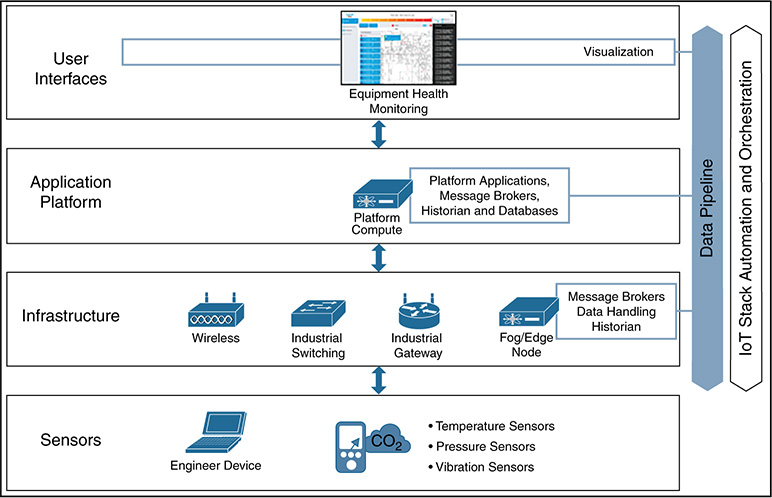
The deployment includes the following elements:
■ Sensors deployed on key equipment transmitting process data and engineering access devices such as ruggedized laptops and mobile devices.
■ Infrastructure to provide communication inside and between levels.
■ Fog or edge nodes that provide real-time edge processing and forwarding of critical data.
■ Unified centralized dashboards for both operational and historical data analytics, as well as utilization and visualization of the sensor data.
■ Platform services at each level and between levels. This includes the orchestration and automation to deploy and manage the use case, as well as an IoT message bus/data pipeline to handle the data from the sensor to locations where it will be consumed.
The automation of this use case is critical because customers look to scale and deploy services at speed, in a repeatable and consistent way. However, it is essential to understand that equipment health monitoring is not about just producing a lot of new data. The data must consistently be of the right quality. The data must be processed in different ways, such as in real-time processing at the edge to transform or normalize data or in aggregating data for meaningful analysis (such as for optimization services). Mechanisms must turn the analysis into useful insight and action. Other mechanisms must collect and transport data to where it needs to be consumed, at the right time, to most effectively leverage data and prevent data leaks. In some scenarios, manual intervention still will be needed to change an asset’s operating characteristics.
McKinsey believes this approach must be automated. It also must be secured. Only then will it provide the greatest impact to oil and gas companies. McKinsey’s view follows the elements in Figure 15-19, the automated support of real-time decisions and actions to reduce planned and unplanned downtime. This model requires the following elements:
■ Data capture: This involves automated hardware sensors and manual data capture by engineers when no automated collection exists. Both should be deployed based on a detailed analysis of use, which is a method for gathering the functional requirements of applications. Hardware sensors should ensure sufficient coverage of data, as well as provide redundancy via storage and backups for high-value measurements of equipment-performance data.
■ Data infrastructure and data management: Data infrastructure, ranging from transactional data in relational databases to data in Big Data analytics platforms, should provide the capability to combine data from disparate sources (both automated and manual) for help in decision-support analytics. Infrastructure should also support real-time data streaming in situations that require immediate data availability.
■ Data analytics: Analytical models should be used to predict failures of critical equipment components. The next level of sophistication includes connecting different use cases, or parts of the value chain, to provide additional optimization services such as streamlined logistics or automated ordering. It also includes using simulations, such as via a digital twin, to test failure scenarios in platform operations.
■ Data visualization: Software applications are needed that present data and insights in a way that is closely tied to priority operational and business decisions. One example is knowledge systems that recommend actions to maintenance engineers. The engineers then can take into account previous repair approaches and the specific history of the asset.
■ Automation: Deployment of the use case infrastructure and applications, as well as operation of the use case, should be automated when possible. This addresses staff skill shortages, particularly for newer applications.
■ Security: It goes without saying that security is an inherent aspect of all the listed elements.
Deploying the Use Case
The equipment health monitoring use case is designed to detect unhealthy conditions of a system that might indicate nonoptimized performance or suggest that the equipment is leading to a fault. Data is created by sensors on the physical plant assets and pushed into a data pipeline where it can be analyzed both in real time at the edge of the system and in aggregation or central locations for historical analysis. The data is presented to operational dashboards so that system operators can visualize and leverage this in a near-real-time manner as part of their tasks. Alternatively, the data can be sent to databases so that applications can process historical data. As Figure 15-20 shows, information can be processed at the edge, can be presented to operational dashboards in the control room or enterprise levels, or can be sent to historical applications in the enterprise or cloud levels.
The use case has four main aspects:
■ The supporting infrastructure to enable communications
■ The data pipeline and supporting applications to collect, transport, and utilize the data
■ The orchestration and automation elements to quickly and reliably deploy the use case
■ The security technologies for the use case
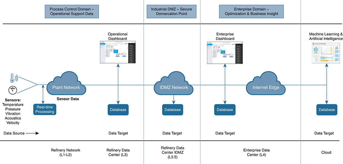
How the use case is deployed architecturally can vary, based on customer philosophy and the team responsible for the use case. In some deployments, the operational team is responsible for the solution and technologies deployed at Level 3 of the security architecture, with information from the data pipeline being pushed to the enterprise at Level 4 via the Level 3.5 IDMZ. In other scenarios, the enterprise team might be responsible for the monitoring use case and might push security capabilities from the enterprise securely into the IDMZ and then into the operational domain. Knowing the deployment model is important, to ensure that the security architecture is not broken. From a platform perspective, it can be deployed in a hierarchical and distributed fashion or can be centralized. Therefore, the MANO element can be deployed at the L3 operational level, in the L3.5 IDMZ, in the L4 enterprise, in the cloud, or any combination.
Typically, in the highly secure oil and gas architectures, any data from the data pipeline perspective that originates from within the operational domains needs to pass into the L3.5 IDMZ before it becomes accessible to the enterprise or cloud services, based on security policy restrictions. In reverse, any deployment that initiates from the enterprise or cloud needs to pass into the IDMZ and go through security policy before accessing a jump server or proxy and being granted access to the operational domains.
Figure 15-21 shows an example deployment architecture from an oil and gas major proof-of-value project. It includes some of the technologies leveraged. In this example, the enterprise team provided a holistic foundational IoT platform to automate use cases for any part of the business (for example, IT, OT, buildings, and enterprise). The components and interactions appear in the diagram.

The use cases consist of the following elements (see Figure 15-21):
Sensors and engineer devices that are either connected to the equipment to be monitored or connected via the wireless infrastructure to manage local PLCs/controllers that control the monitored assets. Typical sensors are used for temperature, pressure, vibration, velocity, and acoustics; they are connected to parts of the assets such as motors, drives, and pumps. The sensors are produced by a number of process control vendors, including Emerson, Honeywell, Schneider Electric, and Yokogawa. As described earlier, in refineries and processing plants, wireless enables new sensors to be easily added to both existing and new assets; the sensors also can be wired. Engineering devices include ruggedized and sometimes intrinsically safe handsets, laptops, and tablets.
A communications infrastructure that enables the transport of the information flows of the use case. This includes wireless infrastructure components such as access points and wireless controllers, switching infrastructure, routers, and gateways. Depending on the part of the plant in which the infrastructure is deployed, it might need to be hardened to industrial specifications. On the plant floor, the infrastructure must be ruggedized to meet specific industry requirements (such as for hazardous locations, temperature, vibration, and shock).
A security infrastructure that secures the infrastructure and information flows of the use case. This includes firewalls, identity and policy management, behavioral analysis, and IPS/IDS.
A computing infrastructure is needed to support the use case applications. Applications can be virtualized, to run in virtual machines or containers. Computing requirements might exist for the plant at the edge and fog layers, in the plant data center, the plant IDMZ, and the enterprise data center.
A device connector (in this case, an EFM DSLink) is required to connect the sensor to the data pipeline message brokering system, or for any applications to subscribe to the sensor data from the data pipeline. The connector must speak the appropriate industrial protocols to connect to the sensor (such as MODBUS or DNP3). Data can be normalized and processed in real time, or stored and forwarded later.
The EFM edge message broker at L3 receives data from the connector and publishes this into a data pipeline as part of a specific topic. Multiple sensors and multiple brokers might be providing this service. Appropriate listeners (applications and other brokers) subscribe to the topic and receive the sensor data.
A local EFM IoT historian database provides a historical store of sensor data.
The EFM L3.5 IDMZ message broker subscribes to the data topic and publishes this information. In this scenario, the IDMZ historian and operational databases subscribe to the information.
The IDMZ EFM IoT historian stores sensor data from the operational sensors. This is made securely accessible to the enterprise or external services. It also provides the capability to assess individual or aggregated data through time.
An operational visualization tool (EFM) subscribes to the message broker to access the data. It displays this real-time data in an easy-to-consume way so that equipment operators can leverage it for optimization or maintenance services.
Information is pushed along the data pipeline from the L3.5 message broker to an EFM enterprise message broker at L4. The message broker publishes the sensor data.
An EFM DSLink connector enables subscribers to receive and understand published sensor data.
An EFM enterprise operational dashboard subscribes to the message broker to access the data. It displays this real-time data in an easy-to-consume way so that it can be leveraged for optimization or maintenance services.
EFM enterprise IoT historian databases subscribe to the message broker topic to access the data. Data is stored and provides the capability to assess individual or aggregated sensor data through time. This data can be leveraged for planning and optimization purposes. Enterprise applications, such as machine learning and Big Data, also can use this information.
Data can be published outside the organization to cloud-based tools such as to Arundo, hosted in the Microsoft Azure cloud. Cloud applications, such as machine learning and Big Data, can leverage this information.
Finally, the MANO provides the IoT orchestration elements.
As described earlier in the book, the data pipeline provides services to control and manage the data plane, including IoT applications and microservices, real-time and historical analytics, data filtering and normalization, and data distribution such as message broker services. This also includes visualization applications to turn the information into insight. Figure 15-22 shows the data pipeline architecture overview for the equipment health monitoring use case. Chapter 11, “Data Protection in IoT,” gives a detailed, in-depth analysis of data pipelines and message brokering systems.

It is important to outline here that not everything can be automated. Additionally, the level of automation that takes place varies at different stages of the IoT platform operational lifecycle. Figure 15-23 shows the typical phases of the operational lifecycle. Day -0 refers to the initial design and prework/preconfiguration needed. Minimal automation takes place in this phase; automation mainly focuses on processes instead of deploying and operating technologies. Day 0 sees an increase in automation, particularly for the secure onboarding of devices. Day 1 sees a lot of automation as multiple parts of the IoT stack are deployed autonomously. Day 2 also includes a lot of automation, particularly regarding mitigation techniques, performance streamlining services, enforcement of KPIs, and the traditional adds, moves, and changes.
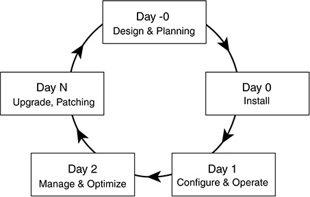
The rest of this section follows the operational lifecycle. We look at the prework required to correctly design and prepare for deployment, explore the automated deployment of the use case, and then cover the security elements from both the network and data pipeline enforcement perspectives. Chapter 13 covers the security of the platform itself (back end, infrastructure, edge and fog nodes).
As a reminder, the detailed platform and security chapters leading up to the use cases appear in Parts II and III of the book. The chapters on IoT architectures and standards appear in Part I. If you’ve come straight to the use case section, note that we explore some of these concepts only at a high level. Please refer to the individual chapters to find in-depth, detailed descriptions of the technologies and platforms outlined throughout the use case. Also remember that although this chapter focuses on oil and gas, the same use case applies across a wide range of industries, including manufacturing, transportation, chemical processing, and power utilities.
As mentioned, the solution deployment can be architected in different ways, depending on the scenario. The platform is flexible and can meet multiple designs without breaking the ETSI MANO architecture standards. For this use case, we use the simplified architecture in Figure 15-24 and outline some of the advanced security capabilities we can automate and orchestrate via the platform. For the simplified architecture example, we have deployed the MANO platform in the operational data center to make the data flows easier to follow.
To deploy this use case, we follow the automation process outlined in Chapter 8, “The Advanced IoT Platform and MANO,” and follow the reference architecture based on the ETSI MANO standard. This section covers the process at a high level; for more detail, refer to the detailed architecture and process descriptions in Chapter 8.

Preconfiguration Checklist
The following well-planned, preparatory steps need to be accomplished before the use case can be automated:
■ Secure attestation and trust of devices: In this case the attestation will be for the edge fog node industrial PC and the Cisco UCS servers. For new devices, the secure onboarding and hardening of the device are recommended, using mechanisms such as TPM/TXT, open attestation, full disk encryption, and OS hardening. This is a one-off activity. When devices are onboarded, the platform MANO has stateful connectivity to each device and all changes are automated.
■ Architected multitenancy and shared services: Multiple parties can share the platform infrastructure and the fog/edge nodes. As an example, the administration of the platform and security capabilities might be the responsibility of enterprise IT in the oil and gas company, but the equipment health monitoring use case and data pipeline could be covered by the OT team. Ensuring that the different TEE environments are properly secured and segmented, as well as providing capabilities to share data securely to the message broker topics, has to be designed and architected before deployment.
■ Application integration and connectors to the sensors: Proper API design and integration into user interfaces, applications, devices, and other systems must be delivered. In addition, southbound connectors to the endpoints are required, to ensure the correct protocols and communications media are supported.
■ NEDs/ConfD for the industrial PC and Cisco UCS server: Ensure that the appropriate device interfaces are designed and built. An IoT deployment might have devices from a number of vendors. These need to be interfaced and connected properly to the system so that all devices are treated in a uniform way as part of an automated deployment.
■ YANG model/Function Pack: In this case, this is the Equipment Health Monitoring Function Pack. Design and creation of the coding blocks must describe their capabilities and services, as well as the associated hardware.
■ Data pipeline operation: A clear definition and plan for how data will be shared, how broker topics will be created, and so on must be designed to bring the deployed services to life.
■ Configuration of ISE and the appropriate security policy definitions created for the sensor traffic flows within the data broker pipeline system: For more details, see Chapter 9, “Identity, Authentication Authorization, and Accounting,” which covers identity management in detail, and Chapter 11, which covers the data pipeline.
■ Configuration of Stealthwatch for behavioral analysis: For more details, see Chapter 10, “Threat Defense.”
As discussed in Chapter 8, the entire use case deployment should be automated once the device is part of the platform. It is also possible to automate the device connection to the platform, but that is not covered as part of this use case. Figure 15-25 shows the components deployed via the Equipment Health Monitoring Function Pack:
■ The industrial PC housing the FW, the service assurance agent, and the data pipeline components
■ The infrastructure VMs, such as the vWLC, ISE, the Stealthwatch flow collectors, and shared services such as AD, DNS, and NTP
■ The data pipeline components in the data center, the associated virtual environments to run the needed applications previously mentioned, plus the configuration and communications elements of these components to ensure that the use case starts once deployed
The Function Pack provides both the service intention and the instantiation of the service, and is created through the open standard YANG data modeling language. The YANG model is leveraged for both service and device modeling. The orchestration system translates the intention and instantiation to allocate system resource and enforce the corresponding configurations on specific device models, including the policies and agents for service assurance.
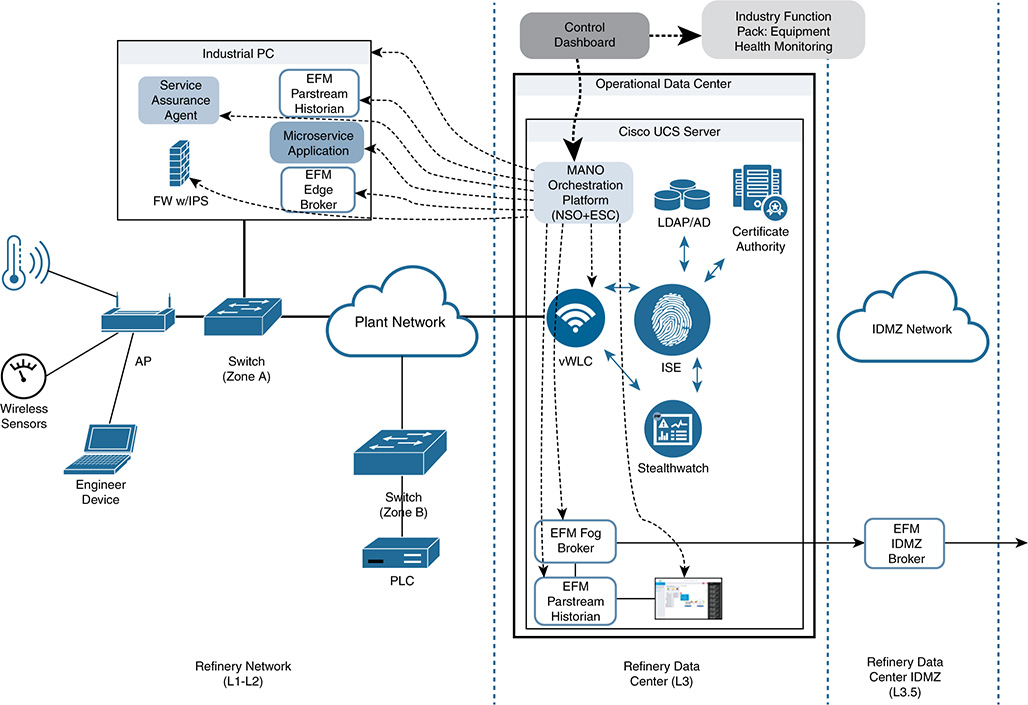
Each element listed previously is created via program code as a capability building block. These blocks are then combined together in the YANG model to represent a Function Pack that the MANO orchestration system will read, allocate resources to, and deploy as configurations throughout the distributed system infrastructure. Figure 15-26 shows an example. This will be fully automated, service centric, and end to end through the distributed IoT platform.
Figure 15-27 shows the flow for deploying the use case services from the back-end perspective; it consists of a number of automated steps. Steps 1, 2, and 3 are completed via a human selection on the user interface while logging in to the dashboard and selecting the Function Pack to deploy. Each step is detailed in Chapter 8. This could also be an automated decision in response to a predefined trigger, based on the contextual automation approach mentioned in Chapter 8; for this example, however, it is a user-instigated, manual process (and this is the most likely scenario in real-world operations today). The remaining steps are automated as a result of the initial selection and deployment commit.
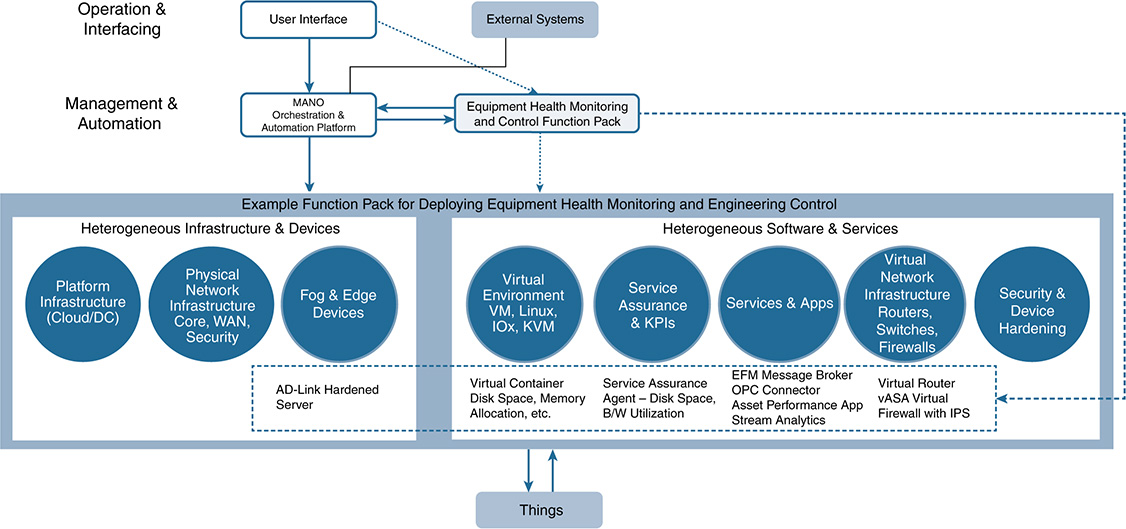

Automated Deployment of the Use Cases
The steps to deploy the automated use case follow:
1. The predefined tenant administrator logs in to the management user interface. Based on the RBAC credentials, the administrator is presented with a view of the system. This includes devices and Function Packs the administrator can deploy, monitor, and manage.
2. NSO provides the ETSI MANO NFV-Orchestrator, which provides centralized orchestration capability for the IoT platform.
3. The administrator makes a Function Pack selection from the orchestration Function Pack library (in this case, Equipment Health Monitoring).
4. The Function Pack consists of a set of capabilities (virtual functions) that will be deployed. These were previously selected and combined from the system catalog of capability blocks. Included are device types and services, as well as configurations that will be deployed to the fog node. This use case includes the server platforms (either an industrial PC or a Cisco UCS server, based on ruggedization requirements of deployment environment), a virtual firewall (Cisco vASA), a virtual router (Cisco ESR), a data pipeline and bus system (Cisco EFM), and service assurance vProbes. In addition, advanced security capabilities can be automated in the same Function Pack, including behavioral analysis (Cisco Stealthwatch) and IPS/IDS (via the vASA). A number of these capabilities can be combined into a fog/edge device base agent to deploy them in a single TEE.
5, 6, 7. The VFM (Cisco ESC) (5) and VIM (OpenStack) (6) provide the orchestration of the virtual environments and deploy the virtual functions inside the virtual machines. This includes instantiating the tenant execution environments (TEE) to host the applications and services in the edge/fog nodes. In a container-based deployment, both of these functions can be achieved via Kubernetes (7).
8. The back-end system interfaces with the fog/edge computing platform via ConfD.
9. The base agent is deployed in TEE0. This includes the core platform services and communications, the service assurance agent, platform service security, and associated databases.
10. The use case–specific applications and services are deployed into their own TEEs. This includes the virtual firewall, the virtual router, the behavioral analytics service, and the data pipeline system.
All parameters to bring these services up and running, and communicating with the back-end platform and other fog nodes, are included as part of the Function Pack, as described in Chapter 8.
At this stage, the use case is deployed from a platform perspective and is ready to collect the sensor data that is pushed to appropriate applications and databases for consumption via the data pipeline. This includes an operational and enterprise dashboard (see the example in Figure 15-28) and real-time and historical analysis of the data. All this is completed in a few clicks when the operator selects and deploys the use case Function Pack.
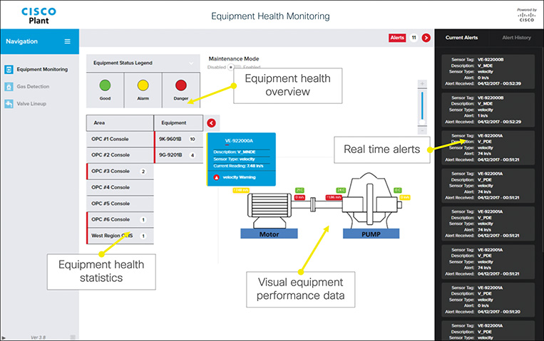
The onboarding of the sensors and the permitted flows of data commence only when the appropriate security checks have been passed. The next section covers this and the automated operation of the advanced security capabilities.
Securing the Use Case
We now explore how to secure the use case, leveraging integration and automation methods.
Security Use Case #1: Identifying, Authenticating, and Authorizing the Sensor for Network Use
This section walks through the various steps required to identify, authenticate, and ultimately pass the appropriate access privileges to the sensor in an automated fashion, eliminating the need for administrator intervention.
Consider the following steps (see Figure 15-29):
The wireless sensor attempts to gain access to the wireless infrastructure and is met with an authentication mechanism (802.1X, MAC Authentication Bypass [MAB], and so on) from the wireless AP. Many wireless sensors in this environment do not support 802.1X, so using MAB is more appropriate in this example.
Note As discussed in Chapter 9, MAB leverages the endpoint’s MAC address as its identity and includes this information in the RADIUS Access-Request frame sent to the RADIUS server (ISE). This requires creating a list of authorized MAC addresses that are input into ISE.
The APs are operating in lightweight mode leveraging a wireless LAN controller (WLC), so the RADIUS Access-Request is sent to ISE, which creates the Acct-Session-ID and Audit-Session-ID.
ISE compares the MAC address against the authorized list and views its policy to determine the response. The MAC address is an authorized MAC address, so ISE returns a RADIUS Access-Accept, along with its access privileges, in the form of a VLAN, dACL, or SGT. We are leveraging SGTs in this use case.
The sensor is granted access to the network and provided an SGT that is analogous to its access privileges. This allows it to communicate with the data pipeline EFM broker and application running on the industrial asset for real-time processing.
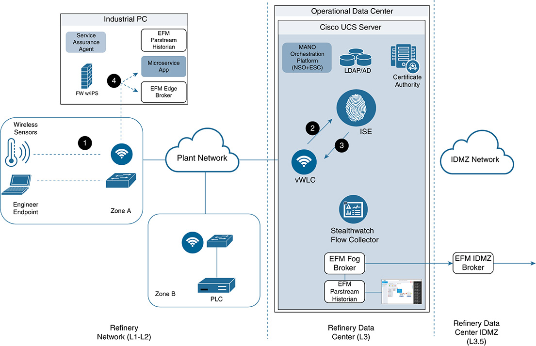
The next step is to carry out a baseline assessment of behavior to determine the standard operating model during normal operations. We can then compare current traffic patterns against the baseline to quickly identify anomalous behavior and potential security threats. This leads us to our next use case.
Security Use Case #2: Detecting Anomalous Traffic with Actionable Response
The Cisco Network Visibility and Enforcement arsenal, discussed in Chapter 10, addresses behavioral analysis and anomaly detection. The solution turns the access infrastructure into sensors by exporting metadata from each conversation in the network via NetFlow from the infrastructure to the Stealthwatch Flow Collector. Stealthwatch then creates a baseline of behavior from which it can begin anomaly detection (potential security threats).
The next phase then is to tie actionable responses to behavior. This is referred to as adaptive network control (ANC) and is accomplished by integrating Stealthwatch with ISE via the Cisco Platform Exchange Grid (pxGrid). pxGrid is a unified framework that enables a subscriber to obtain user and device information (mainly contextual information) from ISE. Stealthwatch supplements the NetFlow information obtained with context such as username and device type, which accelerates the troubleshooting process exponentially.
ISE publishes topics that you can subscribe to, including one that addresses obtaining ISE session information and ultimately enacting NAC mitigation actions on endpoints.
Following the previous model, Stealthwatch registers to the ISE pxGrid node as a client and subscribes to the EndpointProtectionService capability. This allows it to perform ANC mitigation actions on the endpoint, which include quarantining.
Figure 15-30 shows an example of anomaly detection with adaptive network control.
Note The following use case has NetFlow export already configured on the infrastructure and also has Stealthwatch/ISE integration via pxGrid in place.
NetFlow has been enabled on the infrastructure and is being sent to the Stealthwatch Flow Collector, which creates a baseline of communications (destinations, ports, protocols, bandwidth, and so on) and creates a baseline profile for normal operations.
The sensor begins to communicate with its configured destinations but with twice the typical amount of data. Often malicious users can craft malware with if/then logic that can monitor destination, port, and protocol use; then they attempt to leverage those patterns as much as possible to stay “under the radar.” Luckily, Stealthwatch can examine application, port, and protocol use as well as traffic amounts.
The access infrastructure is exporting NetFlow to the Stealthwatch flow collectors, so the influx in traffic deviation is identified.
Stealthwatch invokes a flow through the pxGrid to leverage the adaptive network control (ANC) feature. This provides the option to quarantine the endpoint.
ISE sends a CoA to the WLC to stop traffic from the sensor.
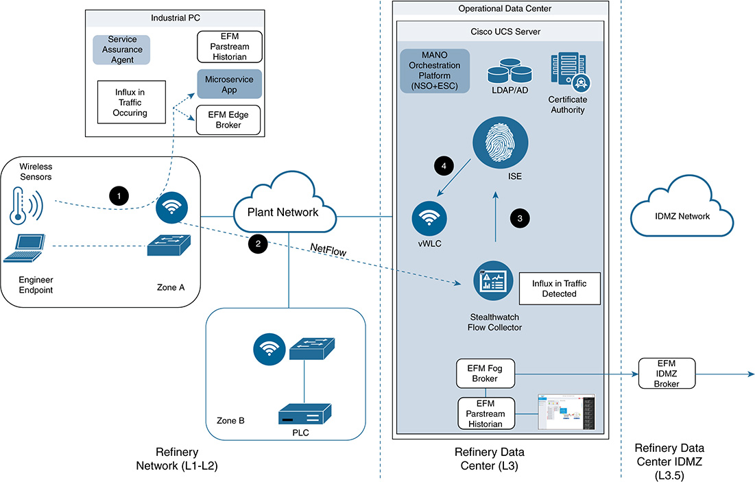
Power of SGT as a CoA
The capability to change one’s access based on suspicious behavior is a common requirement. We’ve been leveraging the SGT (see Figure 15-31) as our CoA method, and for good reason. Using VLANs or ACLs as a method for security is effective, but those methods do not carry the policy intent. SGTs encompass a role in which we can carry the policy intent throughout the network diameter. Additionally, if leveraging SGTs, the infrastructure has the capability to respond to the SGTs in various ways. Traffic can be sent to a SPAN destination or can be rate limited, and can be denied or sent for deeper packet inspection; additionally, we could route traffic down a different VRF. Next, we look at the various actions that the infrastructure can invoke in response to the SGT CoA.

Auto-Quarantine Versus Manual Quarantine
Autoquarantining might sound like an amazing capability, but for endpoints within IIoT environments, it often isn’t feasible. The risk of an accidental quarantine could actually cause harm. Most security operation centers (SOC) instead choose to be notified of the anomalous behavior, with the option to manually quarantine. This provides an extra level of assurance, enabling someone to place a set of eyes on the scenario to ensure that a quarantine is acceptable and justified (given the heightened risk).
Security Use Case #3: Ensuring That Contractors and Employees Adhere to Company Policy (Command Validation)
Considering the heightened risk and responsibility IACS environments have, we might want to ensure not only that the proper network access privileges are provided based on identity, but also that the commands they can execute are policed. These heightened levels of security have proven useful in many IIoT environments. Here we explore a common use case of a contractor connecting to the PLC within the local zone. The company wants to perform command validation for the contractor without blocking its traffic in a later section. Running a device such as an IPS inline within IACS zones is often not feasible because a wrongful block action can result in potential catastrophe. That said, this use case supports performing command validation out of band in passive mode, which does not introduce latency or provide the capability to block.
The main security components we are leveraging for this use case are ISE, to identify the contractor session, and a firewall/IDS/IPS, to perform deep packet inspection for command validation. The policy is configured so that it allows read-only CIP commands to contractors. If a contractor attempts to execute a command outside the allowed list, it is tied to an actionable response (an alert or an ANC action, such as placing the user in a quarantine VLAN).
The following steps take place (see Figure 15-32):
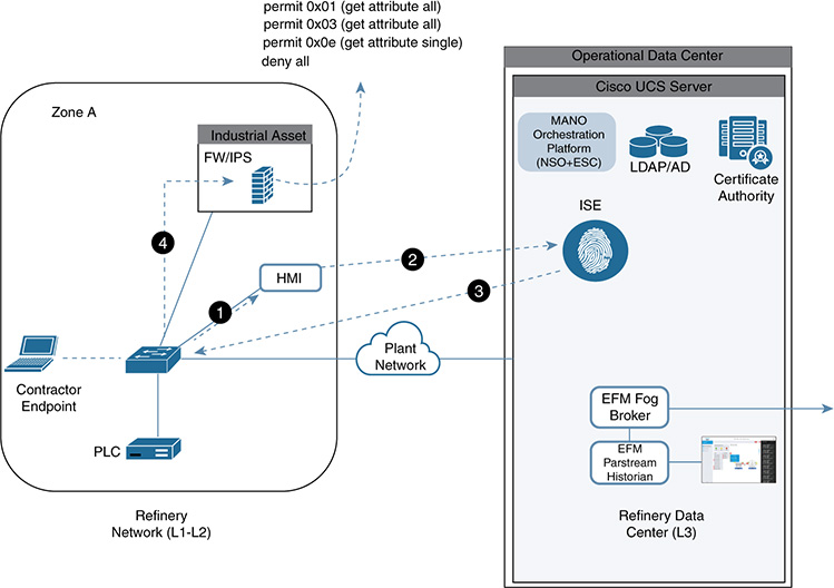
The contractor creates a virtual session into the local HMI.
The contractor signs into the HMI, running Windows 7 with its AD credentials. It is examined by ISE and identified as a contractor asset.
ISE returns the RADIUS Access-Accept along with an SGT of 5 (which identifies the endpoint as a contractor asset). The SGT is applied ingress on that switch port.
As the HMI transmits traffic to the PLC, the switch port sends copies of the traffic (out of band) to the virtualized FW/IPS that was instantiated in the industrial endpoint. The firewall examines the SGT (which signifies that it is a contractor endpoint) and performs command validation. In this example, contractors have read-only CIP access to the controller. If they attempt any commands outside the allowed commands (refer to Figure 15-32), it is tied to an actionable response such as an alert. This also can be tied to an ANC action, such as invoking a flow through ISE to send a CoA that would place the user in a quarantine VLAN.
Leveraging Orchestrated Service Assurance to Monitor KPIs
As noted in previous chapters, networks are becoming increasingly software defined and programmable, and the traditional test and assurance solutions are having a difficult time keeping pace. Testing and assurance mechanisms also require an overhaul to a model-driven assurance approach, which is tied into the service model. One method that is proving successful is leveraging a software-based test agent that performs end-to-end activation tests and active monitoring in an automated way throughout the service lifecycle. This offers an automated approach to validate SLAs, identify issues more expediently, and ultimately resolve issues quicker.
The service assurance agent is deployed automatically as part of the equipment health Function Pack, which is part of the platform base agent running in a virtual environment that is also automatically provisioned by the Function Pack. The service assurance agent is an active or passive virtual probe that runs at specific locations in the distributed system and on the fog or edge devices. It monitors system aspects such as bandwidth utilization, traffic patterns, and disc space. The service assurance agent can be used as an extension of the security services provided by the platform, ensuring that deployed devices, services, and applications do only what they are allowed to do.
Cisco has partnered with Netrounds, a leading provider of active, programmable test and service monitoring solutions for communications service providers. Through the integration of Netrounds and NSO, administrators can do the following:
■ Enable automated activation testing at the time of service delivery
■ Ensure that the services are working as intended to meet defined SLAs
■ Continue validating the customer experience across the service model lifetime
■ Resolve problems quicker
■ Minimize manual field test efforts through automation
This section describes how to leverage a software-based test agent and tie it into the environment to monitor the security process. The service assurance agent is deployed automatically as part of the equipment health Function Pack, as part of the platform base agent running in a virtual environment that is also automatically provisioned by the Function Pack.
In this use case, the virtual test agent or service assurance agent is deployed on the industrial asset/fog node in L1/L2 (see Figure 15-33). This gives the administrator the capability to capture direct metrics about the performance of the service out to that portion of the network as the customer experiences it. This includes stateful TCP and network performance metrics such as delay, throughput, and jitter. It is also possible to validate services across service chains (measuring TCP connect and response times, download rates, and so on).
Baseline performance behavior is achieved via the test agent deployments and reported back to the orchestration systems.
An active service assurance agent, or vProbe (virtual probe), is deployed as part of the Function Pack. This enables configurable periodic updates on performance to be measured as part of the MANO orchestration process and reported back to the MANO platform. In this example, the service assurance agent can monitor the performance of the microservice application and virtual environments on the industrial PC at the edge, as well as centralized firewalling services.

Operators can define runtime key performance indicators (KPI) as part of the service model and configure service monitoring devices to measure them from the right location. They can draw on the orchestration system’s real-time, stateful view of the network and automate the instantiation of virtual probes in the network.
This use case also creates KPIs for the virtual firewalls instantiated in the refinery data center at L3. If the firewalls are detected as hitting a 70 percent connection count threshold, another firewall is instantiated to assist with the load. This is commonly referred to as auto scaling or auto scaleout.
Note The platform and base agents are detailed in Chapter 8. For additional information and screen shots on how to use KPIs for service auto scaleout, see Chapter 10, especially the “Fulfillment and Assurance Sequences Basics” section.
A battery of tests was created to ensure that SERVICE A has been activated and is running as intended. The following testing sequence is captured as a template, which NSO leverages as part of the orchestrated fulfillment process. This is all tied together within the same service data model.
■ An activation test that tests specific ports used in the service and ensures they are active.
■ A TCP throughput test (RFC 6349) to ensure the bandwidth remains at SLA levels.
■ A QoS policy profile test to ensure that application traffic is being prioritized as intended.
■ KPIs for the firewalls instantiated within the refinery data center. The policy is configured so that if the firewall hits a 70 percent connection count threshold, auto scaleout will occur. This then instantiates an additional firewall to meet the load without administrator intervention.
The role of the service assurance agent is to ensure that SLAs are being met. If not, the platform can restart a VM or a service, or send a trigger to an appropriate enforcement device to take actions (such as for ISE to quarantine a particular endpoint).
Security Use Case #4: Securing the Data Pipeline
In addition to protecting the IoT system from the networking perspective, as described in the first three security use cases, we need to ensure the security of data in the pipeline from the initial collection of data, through the transportation of data, to where it is processed. As described in detail in Chapter 11, different types of data need to be protected at the data, management, and control plane levels. For each plane, the specific tools for protecting the data depend on whether the data is at rest, in use, or on the move. As an example, full disk encryption can protect data at rest stored on a hard drive, but it will not help protect the data exchanged between a message broker and a subscriber in a pub/sub data pipeline system. We still have the same security foundations, regardless of the state of the data. We must authenticate entities, authorize entities, and ensure the confidentiality, integrity, and availability of the data, as well as provide nonrepudiation whenever relevant or possible.
Chapter 14, “Smart Cities,” showed how to secure the data pipeline when using an MQTT-based messaging system. This book describes different technologies that have been deployed in customer environments; this use case leveraged the Cisco EFM for the data pipeline. Multiple oil and gas environments have deployed this solution, and it also works in process control environments that require highly distributed technologies with a strong focus on fog computing and IoT. For details on EFM, see Chapter 11.
The data pipeline system (including the message brokers, the DSLinks, data flows to determine how the data is handled in the pipeline, and any associated security parameters) is deployed in a TEE as part of the automated deployment (refer to Figure 15-28). Again, the key here is that all parameters must be deployed at the touch of a button.
The security functions in EFM are built around permissions that determine the capabilities of users, DSLinks (device connectors or adapters), and brokers. In EFM, the notion of upstream and downstream connections is important when configuring permissions either on multiple servers or on multiple brokers within the same server in the data pipeline. A downstream entity typically requests permission, and an upstream entity grants or refuses permission. In EFM, a broker is always considered to be upstream from its DSLinks, although a given broker can be either upstream or downstream from other brokers. These permissions involve two concepts that are quite distinctive compared with the MQTT and RabbitMQ examples in Chapter 11; this distinction involves the way EFM uses tokens and the notion of quarantined entities (for example, the broker and DSLinks).
Tokens are necessary when brokers are configured in such a way that they limit the connection of unknown DSLinks (see the following use of tokens to control which entities are held in quarantine). Note that tokens are never required for DSLinks that this broker manages directly. This occurs when the DSLink is maintained by the broker, which means that a token for the DSLink is automatically generated. Tokens can be created either programmatically or manually. The entities that can create tokens are either a broker or a DSLink. Tokens are created subject to certain parameters:
■ Time range: A string that indicates a time bound up to when the token remains valid
■ Count: An integer that limits how many times a token can be used
■ Managed: A Boolean value indicating that the expiration or removal of the token causes all the DSLinks connected via the token to be removed from the broker
The other distinctive aspect of EFM is the notion of quarantined entities. Quarantine can be enabled on a broker, meaning that any downstream broker or DSLink without an authorized token is kept in quarantine. An important aspect is that quarantined elements can work only as a responder. That is, other EFM elements can read (subscribe to) nodes that are in quarantine, but nodes in quarantine state cannot access other nodes in the pub/sub system. To remove a node from quarantine, users can either authorize the node or refuse its access and remove it from the system.
Fully trusted environments can disable the quarantine process, thereby authorizing entities to connect to a broker without requiring a token for approval. EFM also supports LDAP, as well as local username/password credentials. In terms of the CIA triad, EFM mainly focuses on secure communications between DSLinks and the brokers, and broker to broker. External means are needed to offer confidentiality, integrity, availability, and nonrepudiation end to end, although the quarantine model EFM supports can substantially increase the overall data availability.
This section outlined several security-focused topics that can be automated by the next-generation IoT platform or that have their own security automation capabilities. Multiple technology solution areas can be leveraged to provide a defense-in-depth approach, but this can be time consuming and complex in terms of both design and operation. Only by providing a properly architected interoperable management and orchestration system can a holistic and uniform approach to security be achieved.
These are only a few of the technologies discussed in this book. We strongly recommend reading the detailed and in-depth first three parts, to better understand how the latest technologies can combine with traditional ones to tackle the security of the platform itself and the data and control planes of an IoT system. Chapter 14 discusses the security of the data plane and the data pipeline in a lot of detail in a practical scenario. These same techniques also can be applied to the oil and gas use cases we just discussed.
The next two chapters cover additional technologies for the smart city and the connected vehicle environments. The technologies and some of the elements of the use cases in the following chapters are also relevant and applicable to the oil and gas environment.
Evolving Architectures to Meet New Use Case Requirements
To address and ultimately achieve what oil and gas companies are looking for, we need to ensure that solutions are designed with the following needs and capabilities in mind:
■ Capability to drive tighter alignment between IT and OT in terms of philosophy, design, and operation
■ Systems that can address both IT and OT requirements and use cases
■ Capability to address new architectures being driven by technologies such as IoT and digitization
■ Automation to minimize the complexity of deploying and operating use cases and to increase deployment speed
■ Automation to enforce the deployment of security technologies and the automation of security mitigation techniques
This is inevitable. The industry and the standards are already moving in this direction. Most important, the technologies are now available to make this a reality. Planning to ensure that an organization is ready is an essential activity.
However, this means changes to how solutions are architected and how IT, OT, and supporting vendors/partner work together. As noted earlier in this chapter, new use case requirements are requiring advances in technologies through IoT and digitization, along with a greater desire by organizations to leverage data from multiple sources to best support business decisions. The previous strict approach is starting to change. Figure 15-34 shows how the traditional architecture is morphing to deliver advanced use cases.

IDC research from 2015 further supports this. Automating field operations (any operational area not inside a building) is a high priority for oil and gas companies, and IoT plays a large role in accomplishing this objective. The idea is to replace human labor where applicable, freeing human resources to do more business-focused tasks. Field operations provide the potential for automation, for these reasons:
■ Operating large assets takes manpower.
■ Many assets are located in remote and harsh environments.
■ Vehicles are needed to move supplies and product.
■ Environments are potentially unsafe because of hazardous materials and potential leaks of gas and chemicals.
■ Essential skills are being lost to an aging and retiring workforce.
■ Companies are looking to deploy services as quickly and efficiently as possible, to add value.
■ Automation can enforce both best practices and security.
IDC provides the following advice as part of its predictions on how IoT will positively impact oil and gas transformation:
■ Automation occurs when human labor can be replaced or minimized. It requires immediate, accurate information upon which to operate properly. Hazardous and remote locations in the oil and gas industry are key areas for this to happen.
■ IoT is best positioned to manage the required activities with limited human intervention and decision making. The oil and gas industry includes a number of field environments that can use automation to replace intense human involvement.
■ Wireless sensor networks integrated with cloud-connected production optimization solutions create a potential cost reduction of up to 80 percent.
■ IoT and data management platforms should be designed to work together, following open standards, to provide value. This is a goal of oil and gas firms. Installation and configuration are easier if the same Internet protocol is used to connect to the Internet and if standard formats are used to communicate and share data between applications.
■ Historically, we have faced challenges in creating a solution platform to manage and share data in real time. However, IoT-based technologies can bring together other solution platforms, creating a common method to share data as needed.
Figure 15-35 shows a typical refinery or gas processing architecture. It follows a traditional hierarchical approach, separating the operational and enterprise domains and providing a secure DMZ through which communication and data must pass.
However, new use cases are driving different data flows to ensure that business can take advantage of the produced data. Data flows might need to consider the following:
■ Additional flows of traffic are needed between the operational domain and the enterprise domain to enable better business insight from the operational data.
■ Data is now being transmitted for monitoring purposes directly from sensors at the edge and moving into the cloud so that technology vendors can provide additional analytical services. An example of this is the joint Cisco and Google hybrid edge-to-cloud initiative.
■ Data is now being transmitted for monitoring purposes directly from sensors at the edge and moving into the cloud for industrial vendors to provide enhanced optimization and maintenance services for their customers. ABB, Schneider Electric, Emerson, Honeywell, Yokogawa, Rockwell, and others all provide this type of service.
■ Much more convergence and exchange of data from different domains are occurring through a secure shared bus. The Open Process Automation initiative provides an architecture that supports this developing trend.
As a result, architectures are evolving and will continue to evolve for some time. In the future, they will look more like the one in Figure 15-36. This opens up potential security scenarios that might not have been previously envisioned. Securing these architectures and use cases in as automated a way as possible becomes even more critical, and an open standard interoperable management and orchestration platform is a key element.
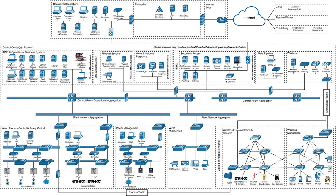

Summary
A recent EY survey of global executives showed 61 percent of oil and gas companies are experiencing positive financial change as a result of digital transformation. The use of IoT-enabled technologies can have a positive impact in the industry in these ways:
■ Improving the efficiency of operations, machines, assets, and people
■ Reducing nonproductive time of the workforce and downtime of operational assets
■ Ensuring that work can be completed the first time in the right way
■ Reducing time in making decisions, to reduce exposure to risk, safety, and security issues
■ Increasing the speed of deploying new services
■ Reducing exposure to risk, safety, and security issues
Automation will play an increasing part in the oil and gas industry (see Figure 15-37), particularly with changes in the skill sets of the workforce and the need to more easily deploy new services. Through consistently automating industry processes and decisions, deploying new services, and responding to security threats, opportunity is arising to standardize the approach to meet company objectives, even as skill sets disappear or new security threats arise. A new, cross-skilled workforce also develops faster and has a quicker positive impact on business, while at the same time as minimizing the time needed to perform tasks that are currently manual or mechanized.
A McKinsey study found that companies have successfully pursued automation programs for production efficiency. Typically, these companies have adopted strategies that include multidisciplinary teams, bringing together IT, OT, security, and sometimes process automation vendors.
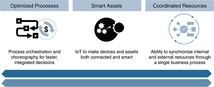
McKinsey believes the best success will come through a corporate digitization program that makes automation part of its foundation. Automation technology is integrated with multiple aspects of the organization, work processes, and human behaviors.
A clear and standardized automation approach in oil and gas will provide a competitive imperative for increasing profitability. Companies that successfully combine and implement IoT, Big Data analytics, security, and other new technologies will be best positioned to meet their industry’s challenges.
An advanced IoT platform delivering these automated capabilities will result in the following (according to Deloitte):
■ Upstream companies will focus on optimization to gain new operational insights by standardizing the aggregated data and running integrated analytics across the functions (exploration, development, and production).
■ Midstream companies will target higher system availability and integrity, and find new commercial opportunities. These companies will benefit from investing in an IoT platform that securely touches every aspect of their facilities and that can analyze operational data more comprehensively along their pipeline systems.
■ Downstream companies operating at an ecosystem level will create new value by expanding their visibility into the complete hydrocarbon supply chain, enhancing core refining economics, and targeting new digital consumers through new forms of connected marketing.
An FC Business Intelligence 2018 Market Outlook report summarizes this well. The report sees automated, data-centric software solutions delivering powerful productivity and collaboration tools that provide the following benefits:
■ An increase in the speed and quality of decision making.
■ Early identification and mitigation of risks.
■ Seamless, single-source-of-truth data among all participants in a value chain. This can include the owner (IT, OT, security), multiple contractors, subcontractors, vendors, and suppliers.
■ Intelligent analysis of information using purpose-built algorithms.
■ Data that is captured, analyzed, and shared in real time.
■ Reliable data for benchmarking performance and passive, nonintrusive data collection to continuously evaluate project practices.
■ A workflow-focused, automatic dissemination approach.
Price Waterhouse Cooper suggests that most oil and gas companies view information technology and digital activities as unrelated to the core business. As a result, they operate as a siloed business. The recommendation is to take advantage of an automated, cross-functional platform to address business needs. Being able to make this fundamental shift in both strategy and operating model will allow oil and gas companies to capture the potential of digitization through the following:
■ Shared standards: Bringing together operational technology with information technology calls for a common set of standards that meet stringent operational rules. It also allows for information sharing across the organization and provides a way to streamline operations.
■ Collaboration and cross-training: The integration of IoT and digitization promotes multidisciplinary domain knowledge that encompasses IT, OT, data management, process design, and cybersecurity.
■ Security and compliance: As assets become increasingly connected to the data network, it is important to protect the critical digital infrastructure against cyber attacks. This can be done by monitoring threats, identifying vulnerabilities, installing robust controls, and promoting a culture of security awareness.
Although there has been innovation across the industry sectors, until recently, there have been no end-to-end digital solutions common to the business and no clear leaders have emerged in the market space. A 2017 Accenture study found the energy industry to be slow on the uptake, with oil and gas lagging behind most. But that is changing. The approaches shown in this book have the capability to transform the industry further. As an example, Cisco is already working with a U.S.-based oil and gas major and has developed a joint IoT foundation lab that includes the technologies and use cases outlined in this chapter. The aim is for the platform to be the reference platform for any (enterprise or operational) IoT use to be deployed as the organization builds out its standardized deployment methodology.
References
http://reports.weforum.org/digital-transformation/wp-content/blogs.dir/94/mp/files/pages/files/dti-oil-and-gas-industry-white-paper.pdf (amended with external link)
http://www.ey.com/us/en/industries/oil---gas/ey-why-the-time-is-right-for-digital-oil-companies
http://www.bain.com/publications/articles/becoming-digital-oil-and-gas-company.aspx
http://www.macrotrends.net/1369/crude-oil-price-history-chart
http://www.offshoreenergytoday.com/top-10-cyber-security-threats-for-oil-and-gas-industry/
http://www.ogfj.com/articles/print/volume-13/issue-11/features/cyber-attacks-on-the-rise.html
https://www.abiresearch.com/press/cyber-attacks-against-oil-gas-infrastructure-to-dr/
https://www.accenture.com/us-en/service-creating-smarter-safer-refineries
https://blogs.cisco.com/sp/orchestrated-assurance-what-is-it-and-why-do-i-need-it
https://www.controlglobal.com/articles/2017/rockwell-automation-11/
https://www.controlglobal.com/articles/2017/rockwell-automation-25/
https://www.mckinsey.com/industries/oil-and-gas/our-insights/digitizing-oil-and-gas-production#0
https://www.statista.com/topics/1783/global-oil-industry-and-market/
https://www.strategyand.pwc.com/media/file/Not-your-fathers-oil-and-gas-business.pdf
https://dupress.deloitte.com/dup-us-en/focus/internet-of-things/iot-in-oil-and-gas-industry.html
Cisco Services, “Where to Begin Your Journey to Digital Value in the Private Sector,” 2012.
Niven, C, “PIDC Perspective: Oil Field Optimization—IoT and Device Connectivity Strategies,” 2015.