Chapter 11. Data Protection in IoT
Topics covered in this chapter include
If we ask a group of technologists across different fields the question, “What is data protection?” the answer will vary considerably, depending on their area of expertise. A backup administrator will associate data protection to backups and data restoration processes, whereas storage administrators will think about data persistence, storage replication, and Redundant Array of Independent Disks (RAID). An expert on General Data Protection Regulation (GDPR) will immediately think about protecting consumers’ personal data. A security consultant will probably associate data protection with the set of mechanisms needed to secure data at different levels. In summary, data protection means different things to different people in different contexts.
For the purpose of this book, data protection is the combination of proactive and reactive technologies and mechanisms, along with best practices on securing data in an IoT platform. It is about preventing unauthorized access to data and securing its use during its entire lifecycle, including data produced at the data plane, control plane, and management and operational planes. As Preston de Guise says in his book Data Protection: Ensuring Data Availability, data protection goes beyond the responsibility of IT departments. It should be the result of close collaboration and strategic alignment among IT, OT, and the different lines of business (LoB) that make up an organization. In this chapter, our focus is obviously IoT, a field in which ensuring tight coordination among IT, OT, and LoBs is key to protecting sensitive data.
However, data protection in IoT is far from trivial. A number of technical and nontechnical factors make developing security mechanisms to protect data a challenging endeavor. For instance, several industries are currently transitioning from legacy systems toward new digital IoT platforms. Obviously, this transformation process will not occur overnight. In most cases, the transition involves the coexistence of brownfield and greenfield technologies for years. Many of the brownfield technologies that need to remain operative were developed in the 1980s, and it is not uncommon to find elements in an industry plant that were designed without any security. Additionally, some of those unsecure elements could be part of key productive processes, so the data that they use and produce might be critical for the plant. At a glance, we can think of a number of potential palliatives and add-on technologies to protect the data used and produced by unsecure elements in a data pipeline. Unfortunately, adding such elements might be impractical or simply unfeasible due to safety regulations. For example, operators of an industrial control system (ICS) might need to access the data in those elements in real time (for example, in plain text during production), but personnel in the industrial zone might not have the means, training, or time to deal with secure data. As mentioned previously, safety might be another obstacle because adding new hardware or software components to secure data on existing machines and elements in an ICS might demand the re-homologation of certain safety and quality processes.
In practice, the approach most ICSs follow is quite different. As described in Chapter 5, “Current IoT Architecture Design and Challenges,” ICSs are supported by the layered architecture in Figure 11-1. This is based on the standard IEC 62443, which is the successor of the well-known Purdue Model for Control Hierarchy and the ISA 95 standards. The ultimate goal of ISA99/IEC 62443 is the availability of ICSs (and the data), followed by data integrity. As Figure 11-1 shows, the model outlines six levels of applications and control in a manufacturing enterprise (Levels 0–5), arranged into four main zones (the cell/area zone, the industrial zone, the DMZ, and the enterprise zone.
Level 0 includes the sensors, drives, actuators, robots, and instrumentation elements that are necessary to carry out a manufacturing process. All of them produce data and, in practice, many of these elements have limited security or even no security at all. To defend against security threats on the data at Level 0, the elements at this level are typically isolated from the outside world. All communications are supervised and controlled, including short-range radio communications. Preventive mechanisms are also in place to avoid insider attacks, either intended or unintended because of negligence or involuntary mistakes. For instance, in some cases, operators cannot even access the lower levels (Levels 0–2) with their own mobile phones and need to use dedicated radios for internal communication. Increasingly, IT devices in a plant will have fewer I/O ports exposed (for example, free USB ports waiting to be used), which an attacker can potentially exploit to inject malware.

Figure 11-1 Segmentation of Responsibilities and Data in a Manufacturing Enterprise, Adhering to IEC 62443 and the Purdue Model of Control
The devices in Level 0 are controlled by the elements depicted in Level 1; they are typically responsible for batch, discrete, sequence, and hybrid control. The elements in Level 1 include programmable logic controllers (PLC), distributed control systems (DCS), remote terminal units (RTU), and so on. The next level in the hierarchy is the area of supervisory control, or Level 2. It includes the manufacturing operations equipment for an individual production area and typically covers the following components:
■ Human Machine Interfaces (HMI)
■ Alarm systems
■ Engineering and control workstations
A considerable part of the data used, produced, and exchanged at Levels 1 and 2 is critical for a manufacturing enterprise, so protecting this data is vital for the business. Therefore, similar considerations apply here.
The next level covers manufacturing operations and control (Level 3). The applications and elements at this level include the following:
■ Production control, scheduling, and reporting systems
■ Optimization control
■ Historian data
■ Domain-specific controllers
■ Remote access in a highly supervised way
■ Network file servers and IT-related functions that support the operational processes and tasks at Level 3 and below
Observe that some of the applications and elements in the industrial zone can communicate with the systems in the enterprise zone through the DMZ. The DMZ provides secure access and control, enabling data between these two zones to be exposed and delivered in a controlled way. In practice, direct communications between Levels 0–3 and the enterprise zones (Levels 4–5) are strongly discouraged, so any potential data exchange is supervised and goes through the DMZ. The DMZ segments and separates the OT domain (Levels 0–3) from the upper levels.
Levels 4 and 5 relate to site business planning and logistics and the enterprise network, respectively. Level 4 is often perceived as an extension of Level 5; it includes elements for managing inventories, handling capacity and business planning, reporting, scheduling, planning operation and maintenance (OAM) tasks, and so on. Level 5, on the other hand, is where the corporate IT infrastructure and applications reside. The elements, applications, and data in Levels 4 and 5 are usually managed and secured by corporate IT.
The hierarchical model in Figure 11-1 not only separates roles in an ICS but also segments how data flows are controlled. Its aim is to protect the data produced and used at the different levels. For instance, enterprise applications and decisions made at Levels 4 and 5 are fed from data supplied by Level 3. This is typically performed in a secure way through the control boundaries imposed by the DMZ. Although this model has historically governed ICSs and the way manufacturing enterprises were architected and operated, the divide between IT/enterprise and OT services and data is no longer seen as a must. With the advent of IoT, the separation between IT and OT is rapidly blurring. Many use cases enabled through novel IoT technologies often entail smart combinations of IT and OT services to maximize business outcomes. In general, bringing OT to IT is not an option. However, bringing IT capabilities to the OT field is perfectly feasible. This is already happening, driven by the adoption of fog computing powered by orchestration, automation, and data protection. This approach is a game changer in the desired convergence of IT and OT. IT services are becoming operationalized and deployed alongside OT services. This allows one to exploit and extract value of data produced in the field and generate business value in ways that operational technologies are not geared to produce. In summary, even in highly controlled environments, such as ICSs, the way data is being controlled and used is changing. Data protection mechanisms in ICSs will need to evolve and adapt accordingly.
Even though the convergence of IT and OT seems unavoidable, it is still too early to understand its ramifications and its potential impact on data protection techniques. In Part IV of this book, “Use Cases and Emerging Standards and Technologies,” we cover a set of transformational use cases, with special focus on security and orchestration involving a full IoT stack (covering the infrastructure, OSs, virtualized environments, applications, data, service assurance, and more). As Chapter 5 explained, under the hypothesis of a converged IT/OT scenario, the notion of a full IoT stack poses challenges regarding who owns what data and services and, therefore, who is responsible for protecting what data. The advantage of orchestration and automation techniques is that, once IT and OT departments agree upon the definition and lifecycle management of an IoT service and its data across the full stack, orchestrated transactions can also help in automating data protection; this lessens pressure on IT and OT administrators and their corresponding responsibilities. Access to data can be subject to role-based access control (RBAC), which can be automated and enforced as part of the orchestration process. This approach gives different IT and OT administrators access to different classes of data in an automated way.
Clearly, the need for data protection goes way beyond ICSs and the layered model depicted in Figure 11-1. Every industry vertical faces similar challenges, including smart cities, transportation and smart vehicles, utilities and smart grids, and smart buildings. However, the adversary forces and security needs vary a lot from one vertical to another. As described previously, the data managed at Level 0 in a manufacturing plant can be fenced so that it remains isolated from the outside world, to protect the operational processes (see Figure 11-1). However, a smart vehicle works in exactly the opposite way—that is, the operations required cannot keep the data isolated from the outside world. In light of this, data protection mechanisms that historically have been successfully implemented in one particular environment cannot be simply reutilized in other verticals.
No magic formula or detailed recipe can protect data in IoT. Protecting data in a pub/sub system is one matter; in an application enablement framework (AEF) designed for IoT, it is another matter. In a full IoT stack involving fog, network, and cloud infrastructures, data protection is again a unique matter. In fact, this last scenario is very different from the previous two examples. Protecting data in a full IoT stack is more akin to an art than an exact science. So how do we cope with the challenges posed by data protection in IoT? Figure 11-2 illustrates the approach that we follow in this chapter. The methodology used for protecting data is based on the confidentiality, integrity, and availability (CIA) triad; it is supported by access control and complemented as needed with nonrepudiation capabilities. The triad applies to data produced and managed by the three relevant planes (the data plane, the control plane, and the management and operational plane). As we show later in the chapter, it applies to architectures implementing a full IoT stack.
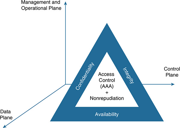
Figure 11-2 Data Protection: The Confidentiality, Integrity, and Availability (CIA) Triad, Including Access Control and Nonrepudiation
Although the requirements related to data protection vary significantly across verticals, the methodology of starting from access control and applying the CIA triad for each of the three planes in an IoT stack offers a plausible approach. Hereafter, we assume a multitenant environment, in which entities or objects belonging to different tenants (sensors, actuators, nodes, users, and so on) produce and require secure access to data at different levels. In a nutshell, the art of data protection in IoT involves at least the following functions:
■ Access control: Refers to restricting data access to only the entities or objects that are allowed to access and manipulate the data. This encompasses the basic functions of authentication, authorization, and accounting (AAA), as well as physical access control.
■ Authentication: Determines who the object is. Unfortunately, many IoT de-vices do not have sufficient resources (for example, CPU power and memory) to support the cryptography utilized by some authentication protocols. To cope with this, new techniques are being developed that aim to build trust between a resource-constrained device and a more powerful fog node that can act as a proxy. The new techniques also seek to outsource resource-intensive computations to the fog node, including the execution of authentication protocols. Gateways provide another example that can be used to enable authentication for constrained devices.
■ Authorization: Determines what the object is allowed to do with the data (for example, the object can only read data, or can publish data, or can modify or even delete existing data). As we show in this chapter, fog also plays a key role in protecting data in multitenant systems. More specifically, fog not only can handle authentication, but also can host and support the authorization and data sharing rights among tenants. Data exchanges across tenants are critical in several verticals, and fog offers a strategic point of control at the edge to mediate and authorize the exchange of data between different tenants.
■ Accounting: Refers to keeping track of the different operations performed on the data and ensuring that those actions are time stamped and securely logged.
■ Physical access: One of the main challenges in IoT has to do with controlling the physical access to devices, especially, for assets in the field. Differently from cloud computing platforms, where gaining physical access to a data center facility is a complex endeavor, assuring that only authorized personnel can physically manipulate devices in the field and access their data is key in IoT. Thus, physical security and the development of proactive methods to restrict access to data produced by cyber-physical systems in the field also lie under the category of access control. It is worth highlighting that access control mechanisms can be complemented by intrusion detection systems (IDS) and intrusion prevention system (IPS). These can be used to discover, notify, and trigger potential actions against unauthorized access or malicious attempts to manipulate data.
Note that the scale and highly distributed nature of several IoT infrastructures makes access control a challenge. However access control is the cornerstone to ensure the confidentiality, integrity, and availability of data.
■ Confidentiality: Refers to preventing the disclosure of sensitive data to unauthorized entities or objects. Note that the terms confidentiality and privacy are often used interchangeably, but they have different meanings. Confidentiality is about keeping specific data secret, whereas privacy mainly refers to keeping secret certain attributes of the data, such as preventing the revelation of the ID of a data producer or the location where the data was produced. Normally, privacy regulation also covers other aspects, such as auditing processes to ensure that data will not be used for purposes other than what they were collected for.
■ Integrity: Refers to preventing the modification of data. A system that offers data integrity provides mechanisms to detect when data has been modified by an entity or object without authorization.
■ Availability: Refers to the capability of a system to ensure service continuity to authorized objects. This usually covers a set of mechanisms to detect potential attacks (for example, a denial-of-service [DoS] attack) and the procedures and countermeasures to either eliminate or mitigate the threat. Attackers typically look for vulnerabilities from multiple angles. In IoT, the adversary forces and attack surfaces that a system needs to defend against vary considerably from one vertical to another. For instance, successfully conducting an external attack targeting the availability of data on a manufacturing plant is hard to achieve (see Figure 11-1). However, successfully conducting a DoS attack in a smart city environment could be much simpler and cheaper. Consider, for example, the case shown in Figure 11-3. Several of the IoT technologies that are currently deployed in cities have adopted the unlicensed industrial, scientific, and medical (ISM) radio bands. Existing regulation imposes clear limitations on the amount of energy radiated and the output power for devices operating in these radio bands. An adversary willing to perpetrate an attack in a city will not be restricted by regulation, so the attacker can produce a device transmitting in the same unlicensed band to intentionally jam the radio signals. By hiding hundreds of those devices in urban spaces, an attacker could potentially affect the data readings of a large number of ISM-based sensors in different areas. City administrators would need to send personnel to the areas affected to find and eliminate the source of the attack. The challenge is that, depending on the output power and the batteries used, these devices might be quite small, so they would be hard to find without appropriate instrumentation. Also note that such devices are cheap and easy to build. Security is one reason why licensed radio bands are gaining traction over unlicensed ones in the space of IoT.

■ Nonrepudiation: Refers to the capability of a system to determine the identity of the entity or object that has originated a certain message or data, along with the necessary mechanisms to ensure that the data producer cannot deny its authorship. Nonrepudiation has to do with proof of data origination. In practice, it is applied together with mechanisms that ensure message integrity. Proving the authorship of a payload is of little help if the integrity of the bearer (the message) cannot be proved as well.
Data protection is essential in IoT, but it is clearly insufficient to secure a full IoT stack. Other aspects, such as securing the platform itself (for example, using trusted computes and remote attestation mechanisms, securing APIs, hardening operating systems, and managing keys and certificates), also play an important role while protecting data. These functions are not specific to data protection, so they are not covered here; instead, Chapter 13, “Securing the Platform Itself,” analyzes them in detail.
Data Lifecycle in IoT
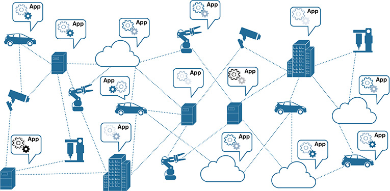
Before digging into the details on how to protect data, it is important to understand the lifecycle of data in IoT, including aspects such as the phases of data processing, which types of data are produced and used, and where the data could reside at the different stages involved in their processing (depending on the use cases). Figure 11-4 illustrates various industry verticals in IoT, including connected vehicles, smart buildings, smart surveillance systems, smart drills and tools, and manufacturing plants with industrial robots. Most of the elements involved in the different verticals in Figure 11-4 produce data. This data is produced by a wide spectrum of applications that can be hosted in vehicles, buildings, manufacturing plants, the robots themselves, NFV-PoPs, the fog, or the cloud. Indeed, these distributed applications can run as microservices, and they can be chained to build IoT services that can be deployed in the continuum between the things and the cloud. The lifecycle of data in an IoT service of this nature typically involves the four phases described in the following list (see Figure 11-5):
Collecting data: This phase corresponds to the process of acquiring and gathering the data produced by the different sources involved in a use case. The sources can be of a different nature and can vary considerably from one use case to another. They include “things” ranging from elementary sensors up to complex machines, external applications for data mashups (for example, weather reports in an agriculture use case), and data supplied by ancillary elements (such as cameras and a human operator). Data collection is not constrained to the data plane; it also covers data produced by the control plane and the management and operational layers. For instance, data can be collected during device discovery, during the registration or rejection of a new device, during configuration changes applied to the control plane, during a remote attestation process, and so on. Data buffering and data aggregation processes are often considered part of the data collection phase.
Figure 11-4 Connected Elements That Are Part of Different Industry Verticals in IoT and a Wide Spectrum of Applications Producing Data
Computing data: After the data has been collected (for example, in raw format), the next step is to process the data. The goal is to extract value of the data. In the case of IoT, this process usually starts at the edge of the network (for example, performed by fog elements deployed in the field). The rationale is simple: Instead of moving data from the sources up to where the computing resources reside (for example, to the cloud), the computing is moved closer to the data sources. This is because moving data to the cloud is not even an option in some cases, for these reasons:
■ Data ownership or privacy policies prevent this (for example, many manufacturing plants will simply not send sensitive data to the cloud).
■ Big Data is created by endpoints at the edge. For operational reasons, sending all the data to the cloud is impractical. For instance, terabytes of data need to be analyzed daily, but the connectivity between the data sources and the cloud is poor (for example, only a few 3G connections are available in the field).
■ Even if moving data to the cloud is technically feasible, the cost of sending all the data to the cloud to perform data analysis can be prohibitive (for example, for anomaly detection and preventive maintenance of machines).
■ Many IoT systems, such as ICSs, require real-time processing and closed-loop control. Cloud-only models usually cannot meet the stringent delay requirements posed by these use cases.
This phase typically covers functions such as data normalization, classification and data analysis, data filtering, protocol adaptations across different media, and the process of making the data available to be transported.
Moving data: An IoT service might consist of a chain of microservices, each with a specific role in the data pipeline (for example, gathering the data, adapting and normalizing data, performing real-time analytics for anomaly detection, persisting data, and creating data mashups for BI tools). Data processing can take place at different levels in both the fog hierarchy and the cloud. Every process or microservice involved in the pipeline receives data, transforms data, and sends the data produced to the next microservice in the data pipeline, including microservices capable of carrying out more elaborated data analysis running in the cloud. Therefore, the capability to move data from one place to another is key for data processing in IoT. This phase usually covers functions such as securing the data transfers and ensuring reliable data delivery.
Leveraging data: This refers to the last stage in a data pipeline or data workflow. It represents the collection of data visualization tools (for example, dashboards), analytics, and BI systems that turn data analysis into concrete business outcomes. To this end, the set of processes or microservices running in the compute resources offered by fog and cloud can work in concert and extract the value of the data at different levels. Whereas Phase 2 (computing the data) usually encompasses the processes for performing data analysis (for example, carrying out anomaly detection), this phase is in charge of notifying operators and decision makers of specific events, making recommendations (such as what to do when an anomaly is detected), or even making decisions in real time without human intervention.

As Figure 11-5 shows, these four phases of data processing lead to the three states data can ultimately take: at rest, in use, or on the move. Data is considered at rest when it is persisted and stored in cameras, caches, files, agent processes, or databases and repositories (for example, for further analysis or backup purposes). In IoT, data is frequently stored in databases hosted in fog nodes, in private data centers, or in the cloud. Data in use refers to data that is currently being utilized; it often entails a transformation process on the data (for example, data being normalized or data being analyzed and subsequently discarded). The utilization of in-memory databases is quite common when data processing requires a very fast response (for example, while data is being used). Last but not least, data on the move refers to data that is being transported for subsequent processing by a node at the network edge, by nodes in a fog hierarchy, or by data center nodes, or data that is simply being conveyed for final consumption using commercial dashboards or BI systems.
The data can be broadly classified into three main categories:
Structured data: Structured data has a high degree of organization and a strict data model in which the content is prepared to fit into a well-defined structure. The data is usually organized in specific fields delimited by labeled columns and rows within named tables, and they are stored in files or databases. Relational databases are popular examples of structured data. Metadata can be explicitly added according to a predefined structure and an agreed-upon data model. This extra dimension (the metadata) usually adds descriptions or data attributes that can help with categorizing, grouping, and reinforcing the meaning of the data. More precisely, metadata facilitates the process of extracting information from the data stored (for example, by simplifying the processes of finding relationships among data in different records). In many of the use cases in the IoT field, the raw data collected at the endpoints (the things) is processed, transformed, organized, and stored in relational databases as structured data. Although structured data has an important role during the lifecycle management of data in IoT, its relevance in terms of volume is relative, given the current dominance of semistructured and unstructured data (see Figures 11-6 and 11-7). Most of the endpoints in IoT produce either semistructured or unstructured data. Data structure is usually achieved after several stages of data analysis, filtering, and processing in a data pipeline.
Semistructured data: Semistructured data does not have a strict data model or a structure that conforms to a high degree of organization (as with relational data-bases or other forms of data tables). However, the data does have a certain structure, usually defined in the form of schemas or self-describing patterns facilitating the ingestion, classification, and analysis of data. Popular examples of semistructured data include XML files and data encoded using XML schemas, as well as JSON, which is broadly used for encoding sensor data. Semistructured data is characterized by a flexible structure, often based on key value pairs—for example, in the form {“data”: {“temperature”: 70.2, “humidity”: 45.0}}. Figure 11-6 gives a simple example of semistructured data. The figure shows a JSON schema to process events received from a temperature sensor. The elements in the tuple [“ts”, “st”, “temp”] at the bottom of Figure 11-6 represent the time stamp, sensor type, and temperature (in degrees Celsius), respectively. This tuple carries the data produced by the event, and it will be encoded in JSON. In general terms, relational databases work with structured data, whereas nonrelational ones (such as MongoDB) work with semi-structured data, often using JSON-like data sets and schemas.
Unstructured data: This data does not have a predefined data model and is not organized in a predefined way. Some examples of unstructured data are audio, digital images, video, PDF files, and Word files. For a human being, this type of data does not have an identifiable structure internally, so the data is meaningless without the right tools for interpreting it (a media player, a PDF viewer, a Word editor, and so on). The process of automatically analyzing and extracting information from unstructured data obviously entails complexities when compared to structured or semistructured data. Although it is relatively easy to query a relational database and find anomalies, patterns, or specific similarities on the data stored, getting the same insights from video or audio analysis is way more complex. The challenge is that the vast majority of the data produced today is nonstructured data (see Figure 11-7); with the expansion of IoT, the volume of unstructured and semistructured data generated will increase dramatically. Recent studies show that unstructured data might account for more than 70 to 80 percent of all data in organizations. Estimations (such as the one in Figure 11-8) forecast that, in only 13 years, data will grow from a few hundred exabytes (EB) in 2007 to more than 50 zettabytes (ZB) by 2020. As you can see in Figure 11-8, data is growing exponentially. As the volumes of unstructured data increase, fueled by IoT, the necessity to analyze and filter this type of data directly (that is, without attempting to structure the data before the analysis) will grow as well. In light of this, automated ways of analyzing unstructured data will certainly keep evolving. Machine learning (ML) and Artificial Intelligence (AI) techniques can work in concert with data mining, natural language processing (NLP), and other tools to interpret unstructured data, filter data, find patterns, detect anomalies, and perform specific actions based on the data examined.
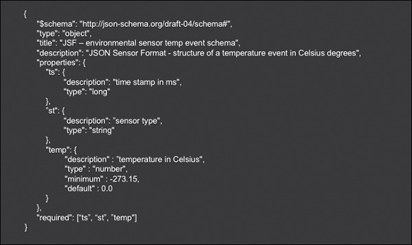
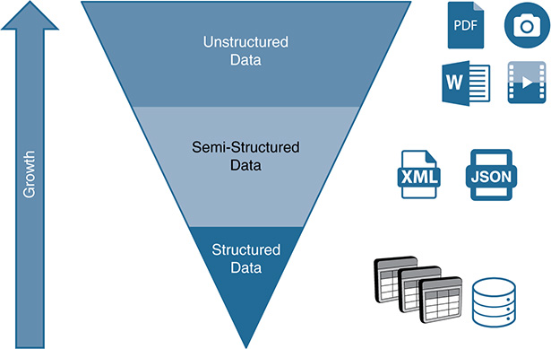
Figure 11-7 Growth and Variety of Data: The Large Majority of the Digital Data Produced Today Is Unstructured

Figure 11-8 Explosion of Unstructured Data (Source: EE Times, https://www.eetimes.com/author.asp?section_id=36&doc_id=1330462)
It is important to highlight that the implications of this categorization of structured, semistructured, and unstructured data are not completely evident. In terms of security, determining whether the data is at rest, in use by authorized entities, or on the move is much more relevant than the structure of the data itself. As described in Figure 11-2, when it comes to protecting data at rest, in use, or on the move, the key is providing access control and ensuring the confidentiality, integrity, and availability of data (along with using nonrepudiation mechanisms whenever needed).
Nonetheless, two aspects can make a difference when planning and budgeting for data protection: the variety and value of the data. These two terms are often identified with Big Data, which has traditionally focused on the well-known three V’s of data: managing big amounts of data (volume), usually measured in terabytes, petabytes, and exabytes; dealing with the velocity of the ingestion of data and providing the means to enable streaming, near-real-time, and batch data processing; and handling the variety of data, including structured, semistructured, and unstructured data. Recent studies on Big Data introduce a fourth V, which accounts for the value of the data. Ideally, all data in an IoT use case should be protected. Unfortunately, this might be unfeasible or prohibitive due to cost.
This is where the variety and value of the data come into play. As we show later in the chapter, the ultimate goal is to transform unstructured or semistructured data collected at the endpoints into business outcomes. In other words, the objective is to convert raw data into knowledge. Obviously, the higher the data is in the knowledge stack, the more value the data has. You might incorrectly think that most of the efforts related to data protection should be devoted to securing the data at the higher layers of the knowledge stack. In practice, if data is compromised at the lower layers, the veracity and value of the data at higher layers are compromised, too. As with any security mechanism, data protection is as weak as the weakest element in a data pipeline. In light of this, the designer in charge of building a service to fulfill the requirements of a given use case needs to take the following actions:
■ Decompose the data pipeline
■ Detect the data sources and data processing elements that are indispensable to accomplishing the desired goals
■ Identify, from a variety of data categories and topics, the ones that are mandatory (the most valuable data)
■ Protect the data at rest, in use, and on the move that is associated with each of the objects identified in the data pipeline
As mentioned previously, the development of automated ways to analyze unstructured data will substantially evolve in the coming years. Currently, however, the most common way to deal with nonstructured data in IoT is to use some form of data normalization. Unfortunately, there is no widely adopted standard for data normalization in IoT, so most of the existing products in the marketplace provide proprietary solutions.
Figure 11-9 depicts a simplified data normalization process. A number or devices supplied by different vendors (D1, D2, …, Dn) are connected by either wired or wireless means. These devices send data to a fog node located at the network edge. The data sent by the various devices carries temperatures, measured in either Celsius or Fahrenheit degrees, and the data can have different structure and formats (for example, they might follow a vendor-specific data format). The data can be transported over different protocols, such as Modbus TCP/IP, BACnet, HTTP/REST, and so on. To process the data reads from the various devices, the fog node offers a data extraction and adaptation layer, which consists of a number of drivers. Each of these drivers not only supports the communication protocol, but also performs the parsing functions of the payload and adaptations required to extract the temperature reads. These drivers can run in the fog node in multiple ways:
■ As independent processes in bare metal
■ As microservices in independent Docker containers
■ As different virtual machines (VM)
■ As different processes or containers in a VM
■ As different listeners of a multiprotocol application running in a single VM, or other variants

After the temperatures have been extracted, the next stage in the data pipeline is to bring those temperature reads to a common, vendor-agnostic format. This is precisely the role of the data normalization layer. In the example, this includes converting temperatures from Fahrenheit to Celsius degrees; all temperature reads are exposed to the next processes in the data pipeline using a uniform data format and temperature unit.
It is important to note that each driver is built for a specific protocol, API, and data format. For instance, if device Dn sends power monitoring data over an HTTP/REST API in the form of the tuple {“data”: {“timestamp”: 1515067723, “sensor type”: SCH1234, “power (KWs)”: 0.2}}, the parsing process performed by the corresponding driver must be tailored to extract the data using the specific protocol, API, and data structure utilized by the device. Frequently, the normalization process shown in Figure 11-9 transforms the input from semistructured data to either structured or semistructured data—though now in a common data format. Depending on their structure, the output data can be persisted in a relational or nonrelational database. These databases can be hosted by the fog node shown in the figure, by other fog nodes in a fog hierarchy, or by nodes in a back end running in a data center.
Currently, the development of the drivers shown in Figure 11-9 is done manually—hence, it takes time. The development effort might take from a few days up to weeks, depending on the complexity of the device and the protocols, APIs, and data models involved. Some companies in the IoT space prefer to talk about connectors instead of drivers. The terminology might differ, but the functionality is fundamentally the same. It is increasingly common to find companies that have already developed hundreds of these drivers or connectors that are integrated into their product portfolios (Cisco, Microsoft, SAP, GE, and so on). This means that sensors and device families of different natures can be connected to a gateway or a fog node; when they interface with the corresponding driver, the exchange of data is immediately available and managed by the driver.
For a technically savvy person in the IT field, this approach might sound a bit strange. In the IoT field, many of these drivers are developed by companies that have not manufactured the devices (the endpoints, or “things”). In the IT field, these are normally developed by the device manufacturer. More specifically, when we buy a printer, an IP camera, or any new peripheral that needs to be connected to a computer, the exchange of data is also handled by a driver. The difference, in this case, is that the driver is usually supplied by the company that manufactured the device. Then what is different in IoT? Why do external companies need to build drivers themselves?
Multiple factors make IoT different from traditional IT and have motivated external companies to develop the own driver catalogs:
■ Many endpoint vendors supply not only the devices, but also proprietary gateways and embedded systems, enabling a complete vertically integrated solution that they sell. They have obviously developed their own drivers, but to protect their business, they do not support portability of their drivers to third-party platforms. With the advent and penetration of fog computing, this is gradually changing. Many companies are realizing the value of open and standardized platforms for customers enabled through fog, which, among many other things, can host these drivers. Economic incentives and new business models are actively being developed to unlock this synergetic paradigm.
■ In other cases, the device manufacturers simply do not have the expertise or sufficient personnel to develop and maintain drivers for various third-party platforms. In some cases, they do have low-level programming expertise (for example, their devices might not even support the IP protocol), but they lack IT personnel who can help containerize their drivers so they can run on a Docker engine hosted by a fog node. As mentioned in the previous point, this is also gradually changing because device manufacturers are seeing the value of IoT and are transforming their business to enable the desired convergence of OT and IT.
■ Maintenance of the drivers is also an issue. In practical terms, a device manufacturer in the IT space generally needs to develop and maintain drivers for five operating systems, at most (Linux, Windows, macOS, IOS, and Android). Unfortunately, the current landscape in IoT is quite different. More than 400 IoT commercial platforms exist, each of which connects endpoints. The model for connecting these devices and then adapting and normalizing the data typically varies from one platform to another. Indeed, many of these platforms run multiprotocol applications, which actually embed the drivers and terminate the protocols at the sensor level. This means that a driver built for one platform cannot be effortlessly ported to another platform. Therefore, a manufacturer of a popular device that already comes with drivers that were externally developed by these platforms has little incentive to start developing and maintaining its own drivers. However, the situation for a new device (endpoint) in the IoT marketplace is different. Instead of waiting for several platforms to embrace its devices and build the corresponding drivers (which might take months or even years for the large majority of commercial platforms), a manufacturer might take the lead and develop its own driver. Obviously, the challenge for the device manufacturers is determining which platform(s) they should focus on in developing and maintaining drivers. Figure 11-10 shows a plausible approach to this question.

Figure 11-10 Automatic Data Normalization in Which the Drivers Are Automatically Rendered Based on a Formal Data Modeling Language
In summary, a combination of factors has prompted third-party companies to develop drivers or connectors, with the aim of accelerating the commercial evolution of IoT. However, this model is progressively becoming a problem for the companies that are developing and maintaining the drivers. Whereas peripherals in traditional IT settings use a limited number of I/O ports and communication protocols, the opposite is true in IoT: The spectrum of wired and wireless protocols, interfaces, APIs, and data structures that need to be ingested and interpreted is much broader and is expanding relentlessly.
Industry and standardization bodies such as the IETF are starting to push for a different approach. The manufacturer usage description (MUD) model described in Chapter 9, “Identity, Authentication, Authorization, and Accounting,” is a good example here. Instead of having a third party developing a new driver to confine the communications of an endpoint to their intended use, the manufacturer of the endpoint provides a MUD file in the form of a YANG model. This model provides machine-readable input based on a standardized and formal data modeling language. This YANG model is basically the “driver” that the platform needs to push the security rules and configurations to switches and fog nodes; its objective is restricting the communications of the endpoint to only its desired use.
Although MUD enables the automation of certain security rules, it does not substitute the drivers shown in Figure 11-9. The next step in the evolution of data extraction, adaptation, and normalization at the edge might look like Figure 11-10. The goal is to enable the automatic parsing and entire data normalization process in such a way that the drivers can be rendered automatically based on the utilization of formal data modeling languages such as YANG. This approach is a win-win scenario for device manufacturers and third-party platform providers. On the one hand, device vendors do not need to develop specific drivers for each platform. As in the case of MUD, they just need to provide data models using a standardized and formal data modeling language that captures the following:
■ The communication protocol used
■ The constraints on the API, following a model-driven API (see Chapter 6, “Evolution and Benefits of SDN and NFV Technologies and Their Impact on IoT”)
■ The data model enabling the parsing of data plane payloads
Platform providers, on the other hand, need to do the following:
■ Create a device discovery module (refer to Figure 11-10) to process the data models supplied by device manufacturers
■ Develop the libraries to render the device drivers automatically based on the data models ingested
■ Build a vendor-agnostic data module (refer to Figure 11-10), which feeds the data normalization layer with the aim of providing a vendor-independent data model for the output data (after the data normalization processes is complete)
The role of the data normalization layer is to map the input data models to a normalized or vendor-independent data model.
Unfortunately, the industry is not there yet. Achieving something similar to Figure 11-10 will take years, especially because standardization efforts are needed. Hence, for the purpose of this book, when it comes to data normalization and its implications on data protection, the focus is on the model used today (refer to Figure 11-9). As discussed previously in this chapter, the key is to protect data at rest, in use, and on the move for the data, control, and management planes through a combination of access control, the CIA triad, and nonrepudiation mechanisms, whenever required. The process of ingesting, adapting, and normalizing data either at the edge or at higher layers in the thing-to-cloud continuum certainly involves data at rest, in use, and on the move; as a result, data protection can be analyzed following the same lines of argumentation. Before transitioning to the specifics of data protection, the next three subsections provide an overview of common scenarios showing data at rest, in use, and on the move in the context of IoT.
Data at Rest
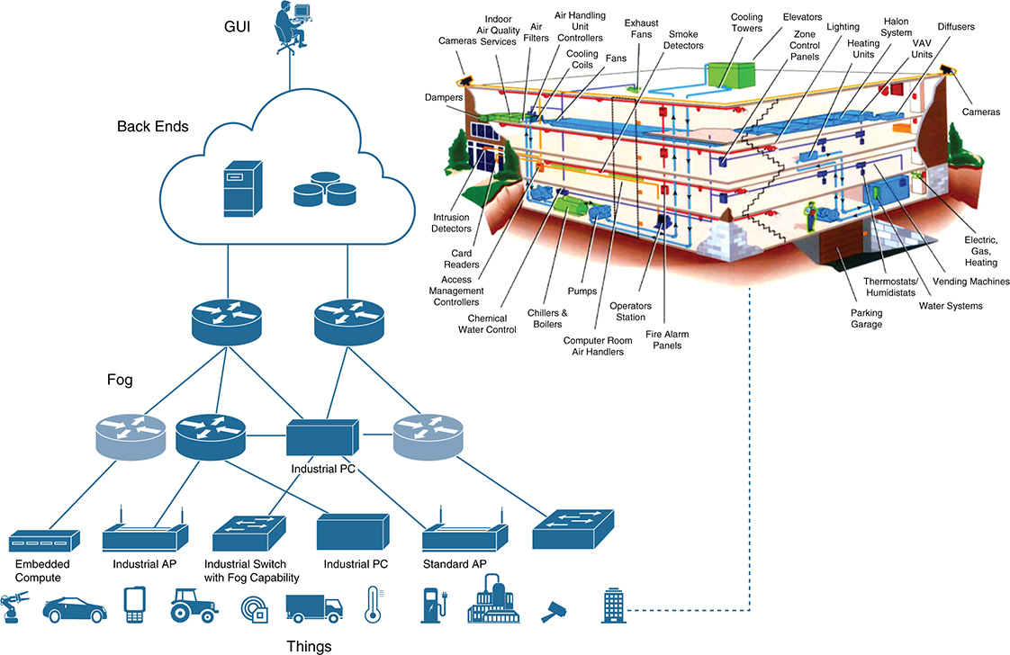
Figure 11-11 shows a simplified version of the thing-to-cloud continuum, with endpoints of different natures at the bottom connected to devices at the edge, such as gateways, access points, switches, embedded systems, and fog nodes with different form factors (for example, industrial switches or industrial PCs). These devices can then connect to other fog and network nodes and through a WAN to one or more back ends running in private data centers, public clouds, or a combination.
In this continuum, data can be found at rest in different locations, including the following:
■ The endpoints (drives, caches, memory, flash, and so on)
■ Fog nodes, which can be located anywhere between the things and the back end (for example, stored in local databases, main memory, caches, virtual storage, and so on). Note that data that temporarily resides in queues in gateways or switches is not considered data at rest; it is treated as data on the move.
■ In the back end (for example, stored in a data warehouse, in a data lake, or simply in main memory or virtual storage provided by a single blade in the back end)
The right side of Figure 11-11 zooms into the commercial building shown at the bottom right. Many of the gateways, access points, switches, and fog nodes depicted in the figure reside inside smart buildings. Building services that were traditionally supplied using legacy technologies (in most cases, using non-IP technologies) are starting to migrate to IP and are becoming part of full-fledged IoT solutions for commercial buildings. This is the case for power, lighting, HVAC systems, video surveillance and physical security, elevators, sensors for environmental control, appliances, and so on. Modern commercial buildings are smarter and represent a clear example of where non-IP-based technologies in the OT field are starting to converge with IT. These buildings might have thousands of Power over Ethernet (PoE) LED light fixtures, hundreds of PoE-enabled fog nodes and switches installed in ceilings and the building automation infrastructure, thousands of PoE HVAC controllers, and many other elements. Most of these elements will store data.
The amount of data at rest in commercial buildings will increase substantially in the coming years. One reason is to ensure that the building can operate autonomously—that is, the core functions must remain operative even if the building loses backhaul connectivity to a central data center or a control room (for example, one that manages multiple buildings). In that sense, smarter buildings will have some form of computational hierarchy, with several fog nodes per floor and cross-functional computation capacity centralized on the premises (for example, in the form of an NFV-PoP). These computational resources will clearly store data.
Another aspect that is highly relevant for data at rest is where to store the data the endpoints collect. A common practice is to use the fog nodes at the edge to store relevant data. In many cases, the communication between the fog nodes and the endpoints is bidirectional. For instance, the fog nodes not only receive data from the endpoints (for example, from sensors), but they also can send data to the endpoints (such as configuration commands and firmware updates). In principle, the endpoints and the fog nodes can exchange data at the data plane (for example, sensor data), the control plane (for example, data related to DHCP and L2 and L3 communication protocols), and the management plane (for example, configuration data and monitoring data). Depending on the use case and the setup, the communications between the endpoints and the fog nodes serving those endpoints might be unreliable. To solve this problem, some solutions in the marketplace use the concept of data shadows or virtual replicas (see Figure 11-12). The goal is twofold. First, it seeks to store the latest reads or status sent by the endpoint and make the data available at the fog node. This means that if the fog node loses connectivity to the sensor, it can still report its latest status (the most recent read). The buffer kept depends on the application, but it can be as simple as the last read received, up to the complete set of reads stored locally in a historian database at the fog node. Second, if the platform needs to configure the device (for example, to change the frequency of the reads), the fog node can act as a proxy, update the configuration of the virtual replica, and wait until the endpoint becomes available again to update it.
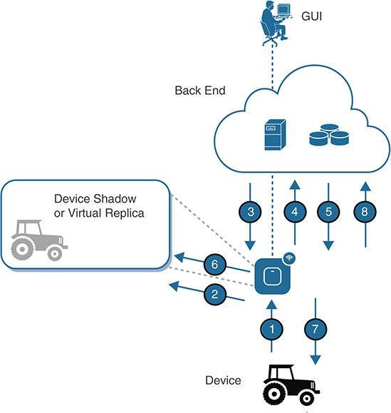
The fog nodes represent a strategic point of control in the field, so they can be used as a proxy or intermediate layer between the endpoints and back-end applications. This is particularly relevant when the communications between the back end and the fog nodes are reliable but the communications between the latter and the endpoints might not be. Clearly, the virtual replicas are persisted in the fog nodes; therefore, they represent data at rest.
Figure 11-12 depicts some interactions with a device, a fog node hosting the virtual replica, and a back end:
The endpoint sends sensor data to the fog node.
The fog node reads and persists the data in the virtual replica.
A back-end application pulls (queries for) data. An advantage is that, if the endpoint runs on batteries, the reads are performed and managed between the back-end application and the fog node without involving the endpoints. That is, the read process does not have any impact on the endpoint batteries.
The fog nodes send the last read stored. Either time stamps or metadata can be used to inform the application about how recent the data is.
The application in the back end now wants to reconfigure the endpoint (change the frequency of the data sent, upgrade the firmware to add a security patch, and so on).
The fog node first sends the new configuration to the virtual replica.
When the replica is updated, it attempts to configure the endpoint. If it fails, it keeps trying until it succeeds or reports the problem to the back end.
Upon successful reconfiguration, the fog node notifies the back-end application.
After analyzing the main aspects of data at rest in the fog domain, the next step is to examine state-of-the-art approaches for storing data in the back end (refer to Figure 11-11). Several IoT solutions use a data warehouse, a data lake, or a combination, so it is important to outline their differences and, more importantly, their synergies.
Data Warehouses
Creating a data warehouse (DW) typically involves the following sequence:
Conducting a requirements study to understand the reports and data analysis needed, as well as storage needs.
Defining the databases needed, their schemas, and their structure, and identifying the main queries that need to be processed.
Identifying the data sources needed to feed the DW (a data lake can be one of the sources).
Implementing an Extract-Transform-Load (ETL) model. This usually involves creating a pipeline to enable the extraction of the required data, as well as adapting and transforming them to fit the schemas defined in item 2. This approach is usually referred to as schema-on-write.
When the DW has been created, the ultimate goal is to enable the analysis of data to facilitate BI, create reports, and so on. In general terms, the data analysis enabled by DW architectures is most effective when it has the following characteristics:
■ Bounds the set of data types used
■ Clusters data with a common meaning to facilitate the analysis and reporting
■ Is optimized for interactive queries
DWs represent a collection of mature technologies that are widely used in the industry, but they also have a number of weaknesses. DWs tend to be quite expensive when very large data volumes need to be managed. Flexibility is also another issue. The schema-on-write approach is excessively rigid in some cases. More specifically, the philosophy DW designs follow is summarized here:
Predefine the structure of the data to be stored.
Ingest the data from the sources defined.
Analyze the data.
Most of the data sources in many relevant use cases in IoT generate nonstructured data. As discussed previously, we are witnessing a paradigm shift with this new philosophy:
Ingest data of any kind and structure.
Analyze the data in its current form (for example, semistructured or unstructured).
Structure data only when needed (that is, only relevant data gets structured, according to the needs). This new paradigm is usually referred to as schema-on-read.
These limitations gave rise to the expansion of data lakes, which are geared to collect any type of data (structured, semistructured, or unstructured) and are tailored for low-cost storage. They embrace the unpredictable and changing nature of data.
Data Lakes
Data lakes (DL) are the center of gravity of many Big Data solutions. A DL offers a very large data repository (for example, based on Hadoop) that can store a vast amount of data in its native format until it is needed.
■ DLs collect many different sources of data in a highly scalable and flexible way. Data sources can be added and removed dynamically, and a large fraction of data can be ingested and stored “just in case” (even if it is not used later).
■ Unlike DWs, DLs target an Extract-Load-Transform (ELT) model. This usually involves creating a pipeline so that the required data can be extracted. As mentioned earlier, data is kept in its native format until it is needed—that is, until it needs to be adapted and transformed. Hence, this approach is known as schema-on-read.
■ DLs manage very large data sets without needing to predefine the data schemas. This allows them to provide the right data to the right consumers with the right structure at the right time (supported by schema-on-read).
■ DLs generally offer a much cheaper approach than DWs, especially for archive purposes. DL infrastructures can be supported on commodity hardware, thereby freeing up expensive resources from DWs (for example, for performing data refinement processes). DLs complement DWs because DLs can be used as a data source for DWs. For instance, a DL can collect all sorts of data but send only specific data to a DW.
■ Whereas DWs are usually optimized for interactive queries, DLs can manage all types of workloads, including batch, streaming, and interactive queries and analysis.
■ Data governance remains key, especially to avoid turning a data lake into a data swamp over time.
A central difference between DWs and DLs is the scheme-on-write versus scheme-on-read models. As Figure 11-13 shows, this is reflected in their corresponding designs. In his work “Big Data Architectures and the Data Lake,” Big Data evangelist James Serra shows how DWs follow a top-down approach that is tailored to facilitate a deductive process in data analysis. This often starts by developing a theory and then creating some hypotheses around it. The data is structured based on this. By performing interactive queries, a set of data consumers can observe and either confirm or revoke the hypotheses made.
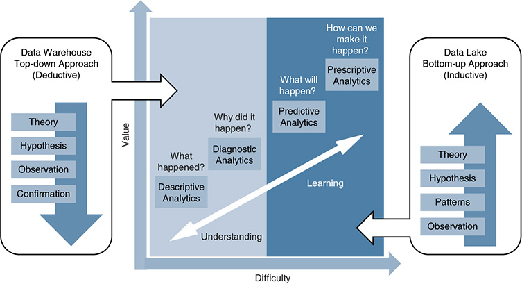
Figure 11-13 Data Warehouse and Data Lake Design Philosophies (Source: “Big Data Architectures and the Data Lake”)
DLs, on the other hand, follow a bottom-up approach that is tailored to facilitate an inductive process in data analysis. They start from a set of observations on different sources of data that can have any type of structure. Based on the observations, analytics tools can search for patterns, which would then support a set of hypotheses and a theory.
As Figure 11-13 shows, deductive processes are good to understand and can answer questions such as “What happened?” or “Why did it happen?” However, they are less efficient when it comes to learning. Inductive processes are much better prepared for answering questions such as “What will happen?” or even more complex ones, such as “How can we make it happen?”
At this stage, the lines between data at rest and data in use start blurring. The left and right sides of Figure 11-13 mainly have to do with data at rest, in a DW, and in a DL, respectively. The central part of the figure represents data in use.
Data in Use
The data produced by an object or endpoint in an IoT environment might have little value individually, but the combination of fog computing, DWs, and DLs contributes to the analysis and correlation of vast amounts of data generated by a large number of entities. Together, this produces relevant information used to understand, learn, and make actionable decisions in real time. These decisions can range from activating control and actuation mechanisms in physical systems, to changing policies or making business recommendations. Those outcomes will also produce data, which again can be transformed into information and, subsequently, knowledge.
The terms data and information are often used interchangeably. In the context of this chapter, the term information represents the outcome of one or more data processing stages in which the output data is presented in a specific context (for example, in a concrete vertical and use case) and with a specific format so that a specific consumer or entity can interpret them in a useful way. Figure 11-14 shows how raw data can be processed, analyzed, filtered, and combined at different levels (for example, using data mashups) to extract information, learn, create knowledge, and, ultimately, create wisdom.
To accomplish this, we can use an architecture such as the one in Figure 11-15. This architecture centers on a DL solution supported by the following stages:
■ Data ingestion: Data comes from a large number of different types of sources, including logs, monitoring data at multiple levels in an IoT infrastructure, distributed applications, LOB data, and sets of IoT endpoints (such as sensors and control and actuation systems). The data ingested can have any format (structured, semistructured, or unstructured) and can be sourced by objects that belong to the data, control, and management and operational planes. Data ingestion can take place in real time, in small batches (or microbatches), and in batch processes. This stage classifies and separates data ingestion that requires real-time treatment (the “hot path”) from data that requires batch processing (the “cold path”). The hot path deals with the ingestion of large volumes of data in real time. The data is usually subject to high variety and is received at very high velocity.

Figure 11-14 Knowledge Stack: Transforming Raw Data into Wisdom (Information Flow and the Value of the Data at Different Layers in the Stack)

■ Data preparation: This stage provides the extract and load operations and relegates the transform operations to the next stage (because data transformation occurs when it is read in the ELT model). Data is stored in its native format (without requiring a predefined structure or schema definition). The hot path typically relies on in-memory databases for real-time processing, whereas the cold path stores raw data for historical reference and analysis.
■ Data analysis and exposure: This stage is where we really talk about data in use. At this stage, insights are extracted from the data using batch, interactive, and real-time (streaming) analytics. Different machine learning techniques can be used to create knowledge. Thanks to the schema-on-read approach, data transformation occurs at this stage, so the output data is ready to be consumed by third parties.
■ Data consumption: Different types of entities can consume the data analyzed and extract valuable information, such as vertical-specific applications, dashboards, BI tools, reporting systems, DWs, and so on.
Figure 11-15 focuses on technologies that are typically deployed in a data center; however, it is worth highlighting that, with IoT, Big Data is not confined to the data center. Big Data is considered the new currency in many fields, including IoT. But what actually is Big Data? In simple terms, Big Data means all data. How big is Big Data? The answer to that question varies significantly, depending on the industry vertical and the specifics of the use case addressed. For example, a set of oil wells can produce petabytes of data daily. A smart city can produce similar amounts of data in one day. Machines in a manufacturing plant might generate data that is orders of magnitude lower, but it can still be considered Big Data in the context of a manufacturing plant. All this data cannot be sent to the cloud, for a number of reasons. In the case of the oil wells, this is often because of limited or unreliable backhaul connectivity (in some cases, the only option is 3G connectivity, and it is available in only a few oil wells). Fog facilitates ingesting, sampling, analyzing, and filtering data locally and then making actionable decisions in real time (for safety reasons, workforce optimization, anomaly detection, preventive maintenance, and so on). Therefore, in IoT, fog computing is a key component of a Big Data infrastructure that, in practice, is built upon computing resources that are much more distributed than the ones shown in Figure 11-15.
A fog node can also offer both hot and cold paths for data analysis (see Figure 11-15) by concurrently hosting streaming and historian analytics. Although the data processing model inside a fog node can be conceptually similar to the one in Figure 11-15, the stages have certain differences. As of the time of this writing, the stages at a fog node level are often organized as follows: data sources → data ingestion → data adaptation (which might include data normalization) → data analysis → data consumption. The adaptation/normalization stage typically transforms the input data to either semistructured or structured data, so it follows more of an Extract-Transform-Load (ETL) model than the Extract-Load-Transform (ELT) model used in DLs. Some applications require persisting raw data in a historian database hosted by the fog nodes, but in practice, most of the use cases adapt the data ingested by the fog nodes before its analysis. Specific examples involving data in use and data protection mechanisms at the fog node level are covered later, in Figures 11-19, 11-30, and 11-32.
Data on the Move
Moving data produced by endpoints at the network edge across fog and network nodes up to the data center is key in IoT. Protocols such as HTTPS, COAP, MQTT, and many others are widely used for transporting data in IoT. For detailed descriptions on protocols such as COAP or MQTT, refer to the Cisco Press book IoT Fundamentals: Networking Technologies, Protocols, and Use Cases for the Internet of Things.
Data produced by one object or entity A often needs to be sent to a specific group of consumers or receivers (B and C). Other data sets, even if they are produced by the same entity A, might need to be distributed to a different group of receivers (C, D, and E). This is a well-known problem in the field of data distribution, where state-of-the-art technologies such as pub/sub systems support this functionality. Figure 11-16 shows several publishers (P) sending data to different brokers (B), which are in charge of distributing the data to the corresponding subscribers (S). The brokers allow for physical and temporal decoupling while distributing data between data providers and consumers. Specific analysis of the data protection mechanisms offered by key pub/sub systems (such as MQTT, RabbitMQ, or, in part, the Cisco Edge and Fog Processing Module [EFM]) is covered later in the chapter, in the sections “Message Queuing Telemetry Transport Protocol,” “RabbitMQ,” and “Cisco Edge and Fog Processing Module (EFM).”
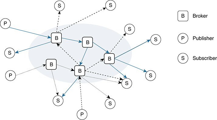
The data distributed by the brokers is usually categorized into classes. Data consumers typically subscribe to one or more classes and receive data for only those specific classes. These classes support selecting and filtering which data needs to reach a given group of subscribers; this selection is generally based on a data topic or specific content. In topic-based systems, data is published to labeled or logical channels called topics. A subscriber receives data published for only the topics that it is subscribed to. Data publishers and brokers usually define the data topics that will be used, and all subscribers to those topics receive the same data. Content-based systems operate in a different way. In this case, data is delivered to a given subscriber if the content of the data matches a set of constraints that are usually defined by the subscriber (for example, in the form of data attributes). In other words, even for the same source data, different subscribers might receive different content. Some pub/sub systems support combinations in which data publishers post messages to topics, and data consumers define content-based subscriptions to a group of data topics.
In many IoT scenarios, the publishers, subscribers, and message brokers run as microservices both in fog nodes located in the thing-to-cloud continuum and in the back end(s) (for example, in a privately owned data center, a public cloud, or a combination). As Figure 11-16 shows, pub/sub systems can route messages across multiple brokers, not only to extend the reachability of the message distribution system, but also to scale and balance the load (including the number of publishers and subscribers each broker man-ages). The brokers normally perform tasks such as message queueing and store-and-forward functions, especially to temporally decouple the delivery of messages between a publisher and its subscribers. More specifically, a publisher might wake up, send a message to a broker, and go back to sleep mode until the transmission of the next message is needed. Similarly, subscribers might be in sleep mode, wake up, connect to their corresponding broker, get the batch of messages stored for them (for one or more data topics), and go back to sleep mode. Another important aspect of a pub/sub system is protocol adaptation. In many pub/sub systems, the publishers and subscribers might speak different languages (that is, they might use different messaging protocols), such as MQTT, AMQP, or STOMP. Protocol adaptations between data producers and consumers are essential. The way of handling these adaptations varies, depending on the implementation. For instance, RabbitMQ manages this through plug-ins to the message broker, turning RabbitMQ into a multibroker/multiprotocol pub/sub system. The Cisco EFM follows a different approach. EFM is based on the Distributed Services Architecture (DSA: http://iot-dsa.org); as discussed later in this chapter, the DSA performs protocol adaptations by means of DSlinks (http://iot-dsa.org/get-started/how-dsa-works).
The use message brokers is popular in IoT, but there are other ways of distributing data between data producers and data consumers in a pub/sub system. For instance, the Data Distribution Service (DDS) offers a pub/sub system that does not require a broker. In DDS, publishers and subscribers share metadata about each other via IP multicast; they can cache this information locally and route messages based on a set of discovery mechanisms offered by DDS.
It is worth noting that the concepts of data in motion and data at rest get intertwined while examining the reliability of a pub/sub system. In a pub/sub system, reliability and availability are intimately related. Recall that availability is one of the central goals in the CIA triad (refer to Figure 11-2) because affecting the availability of resources is the main target of DoS attacks. In terms of reliability, the fundamental questions related to data in motion are what will happen to the data queued and stored if a message broker fails, and whether the data will be available once the broker restarts. To address these questions, most pub/sub systems in the marketplace support the concepts of data persistency, durability, and QoS.
■ Data persistency: In pub/sub systems, this is often considered a property associated with the messages. Some data distribution protocols mark a message as persistent by means of specific fields in the message header (for example, by setting the delivery mode). When a message broker receives a persistent message, it writes it to disk, which allows it to restore the message in case of a restart. Notice that, in most of the existing solutions in the marketplace, when a broker restarts, all persistent messages that were queued pending delivery before the restart are not automatically re-created in the queues. This requires durable queues, as explained in the following bullet. Message persistency comes at a price: Writing a significant fraction of messages to disk can considerably reduce the number of messages per second that a broker can process.
■ Durable queues: The literature is full of definitions and examples related to data durability, and it is important to notice that its meaning varies somewhat, depending on the context (databases, pub/sub system used, storage systems, and so on). Even between different pub/sub systems, the interpretation of the concept of durability might vary. For instance, in AMQP and RabbitMQ, it is usually associated with a property of certain entities, such as queues and data exchanges. Durable entities can survive a message broker restart because they can be automatically re-created when the server gets back up. To make this possible, the messages also need to be persistent because they need to be moved from disk to the corresponding queues after the restart. In the case of DDS, the interpretation is relatively different. The main objective of a pub/sub system such as DDS is to make sure that the data is delivered to the corresponding subscribers, especially all those that are available at the time the data is published. However, subscribers might join a pub/sub system dynamically (these are sometimes called late joiners); for the applications they run, it might be important to access the data that was published before they joined the pub/sub system (that is, access to historical data is key). To allow this, DDS provides QoS mechanisms in the form of a durability QoS policy. This policy specifies how to maintain the data published by DDS, and it supports four alternatives:
■ VOLATILE: When a message is published, it is not maintained for delivery to late joiners.
■ TRANSIENT_LOCAL: In this mode, the publishers store the messages locally in such a way that late joiners can get previously published messages. In this case, the data is available as long as the data writer is active—that is, as long as the publisher remains alive.
■ TRANSIENT: In this mode, the pub/sub system maintains the messages available for late joiners. While in TRANSIENT_LOCAL mode, the responsibility of storing the messages rests with the individual publisher—in this case, the responsibility is moved to the system. Data does not necessarily need to be persisted, so the data is maintained and remains available for late joiners as long as the middleware is running on at least one of the nodes.
■ PERSISTENT: In this mode, the data is persisted and remains available for late joiners even after the shutdown and restart of the whole middleware.
In pub/sub systems, the concept of QoS goes beyond the scope of data durability and involves other aspects, such as how brokers prioritize messages in a queue before routing them to their corresponding subscribers.
Durability and persistence are particularly needed when the data is indispensable. For example, a set of publishers can push data to a queue in a message broker, which a set of subscribers pulls to initiate the execution of specific tasks based on the content of the data. If the broker restarts, the messages in its queue should become available when the broker is back. Otherwise, the tasks that were queued before the restart might never be executed (although this depends on the controls performed at the application level and whether the tasks are managed by a stateless or a stateful application).
A data consumer might subscribe to specific messages at build time, initialization time, or runtime. The large majority of modern pub/sub systems allow subscribers to be added and removed at runtime. A distinctive factor in IoT is that the heterogeneity of publishers and subscribers, data objects, data models, encodings, and protocols can be quite high; some of these aspects are covered in more detail later in Figure 11-30. Data distribution can involve multiple tenants (both trusted and nontrusted); it also might require the enforcement of virtual fences for specific data (for example, certain data are not allowed to leave the factory). Additionally, it might require the use of sampling and filtering techniques before data can be sent to specific subscribers.
Figure 11-17 shows one such scenario, in which data produced by a large machine (an industrial Mazak machine) is sent for processing to a fog node (an industrial switch, in the example) that is connected to the Mazak machine. The Mazak machine can publish multiple data topics, which might have different subscribers. As shown in the example, part of the data is sent to management systems on the premises, other data is sent to HMI for operators, certain data is allowed to be sent to Mazak for statistics and preventive analysis and maintenance, and other data sets are sent to the carpeted zone (a corporate intranet). More specifically, the Mazak machine represents the publisher of multiple data topics, the fog node hosts the message broker, and the elements receiving the data represent the different subscribers. In this example, the export polices applied on different data topics permit sharing specific data with Mazak about its machine, sharing much more data with the company (see Levels 4 and 5 in Figure 11-1), and sharing no data at all with a given partner. All these data flows need to be created and protected. The roles of orchestration and automation are key to this end, not only to enable the different data pipelines required, but also to enforce the security polices authorizing the data exchanges.
Obviously, the concept of data in motion in IoT goes far beyond pub/sub systems. For instance, industrial protocols such as Modbus and its variants (for example, Modbus TCP/IP and legacy serial Modbus systems) are common in IoT, including industry verticals such as manufacturing and utilities. Many other protocols, such as serial RS-485, legacy OPC, BACnet, HTTP/REST, and SNMP, are broadly used as well. The utilization of pub/sub systems in IoT is becoming pervasive, especially to facilitate the distribution of data both within and between fog and cloud environments—see, for example, some of the most recent architectures related to OPC-UA pub/sub capabilities and Time Sensitive Networking (TSN). Indeed, a considerable number of the use cases addressed in this book require orchestration processes that involve the configuration of message brokers such as MQTT, RabbitMQ, or EFM. For this reason, when it comes to data on the move, this chapter focuses especially on data protection in the context of pub/sub systems.

Protecting Data in IoT
After this introduction to the basics of data distribution and the lifecycle of data in IoT, we now focus on data protection. Different kinds of data need to be protected at the data, management, and control plane levels. For each plane, the specific tools to protect the data depend on whether the data is at rest, in use, or on the move (for example, full disk encryption can obviously protect data at rest stored in a hard drive, but it will not help protect the data exchanged between a message broker and a subscriber in a pub/sub system). Nonetheless, the same security pillars apply, regardless of the state of the data—that is, the same needs exist for authenticating entities, authorizing entities, and ensuring the confidentiality, integrity, and availability of the data, as well as providing nonrepudiation whenever relevant.
Data Plane Protection in IoT
This topic deserves a book by itself. To provide tangible examples that can help administrators and developers understand how to protect data, we start the analysis with data on the move and delve into the details of MQTT and RabbitMQ. Then we focus on data in use and data at rest, examining the Cisco EFM as we go. These three technologies and the mechanisms they offer to protect data should provide sufficient foundational insight on the subject.
Message Queuing Telemetry Transport Protocol
MQTT is a well-known and broadly used pub/sub protocol. It allows devices or virtual entities (called MQTT clients) to connect with, publish, and get messages from an MQTT broker (see Chapter 9). As shown previously in Figure 11-16, the MQTT broker mediates the communications between MQTT clients, where a client can be a publisher, a subscriber, or both. Each client can subscribe to a particular set of topics.
MQTT is simple, lightweight, and data agnostic. Features such as the existence of multiple brokers (such as Mosquitto and HiveMQ) and the spectrum of programming languages supported (Java, JavaScript, Python, Go, C, C#, and C++) make it an attractive option for many IIoT applications. Figure 11-18 depicts the potential ports and transport choices MQTT offers.
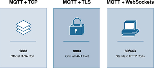
Figure 11-18 MQTT Ports and Transport Choices: TCP (Port 1883), TLS (Port 8883), and WebSockets (Either Ports 80 or 443) (Source: “Securing MQTT”)
Security in MQTT can be divided into three layers, each of which can help protect against different types of attacks. These layers are the network layer, the transport layer, and the application layer. Network layer security refers to using a trustworthy connection through either a VPN or by a physically secure connection. Unfortunately, in many cases, this type of connection is not an option: In IoT, a substantial number of MQTT clients either do not support a VPN client or cannot guarantee a trustworthy connection with the MQTT broker.
An alternative way to create a secure communication channel between two MQTT endpoints is to use transport encryption. By default, several MQTT implementations use TCP as the transport protocol (unless the encryption occurs at the application layer—by default, MQTT endpoints do not encrypt their communications). Today all widely used MQTT brokers support TLS; port 8883 is reserved for MQTT over TLS. A challenge in IoT is that some endpoints cannot afford the communication overhead imposed by the TLS handshake. This overhead is usually negligible for an MQTT broker, but it can be an issue for constrained devices. This is particularly problematic when the devices run on batteries and the large majority of the communications are short lived. A reasonable trade-off offered by some MQTT implementations is to use session resumption, which keeps TLS while improving its performance considerably.
Session resumption allows an MQTT client to reconnect to the broker and reuse a TLS session that was previously negotiated. In other words, the MQTT client and broker do not need to go through the entire handshake process again. Not all TLS libraries support session resumption, but those that do implement it follow one of these two methods:
■ Session IDs: In this case, both the MQTT client and the broker save the last session’s secret state under the session ID. When the corresponding MQTT client reconnects with the broker and provides the session ID, the session can be resumed. To support this, the MQTT broker must keep a cache that maps previous session IDs to the sessions’ secret states. Protecting this cache (data at rest) is critical; an attacker who steals the contents of this cache could potentially decrypt all sessions to be resumed based on it.
■ Session tickets: The MQTT broker secret state is encrypted with a secret key that is known only by the broker; it is sent to the MQTT client in the form of a ticket. When the MQTT client attempts to resume the session, it includes this ticket while reconnecting to the broker. The session is resumed if the broker is capable of decrypting the session ticket.
Widely used MQTT brokers such as HiveMQ support session IDs (but not session tickets). Unfortunately, the low computing budget of some endpoints in IoT makes the utilization of TLS impossible, even with session resumption. When TLS cannot be used, the alternative is to rely on application layer security. The MQTT protocol supports the encryption of message payloads, which at least offers an option to secure the data transmitted when transport encryption is not supported.
Authentication in MQTT
In MQTT, authentication can occur both at the transport layer and the application layer. In the transport layer, authentication is supported by TLS and the utilization of X.509 certificates. In the application layer, the protocol itself supports authentication using the username and password fields defined in the MQTT CONNECT message and, optionally, a client ID. Every MQTT client has a unique identifier (ID), which is included in the MQTT CONNECT message sent to the broker. A client ID can be up to 65535 characters; data available on the client, such as a MAC address or a serial number, can be used to build the ID. These unique client IDs are frequently used in addition to the username and password to build the credentials used during the authentication process.
To avoid sending the username and password (and the ID) to the broker in clear text, most MQTT implementations add a few mechanisms on top of that. The easiest option is the one mentioned previously: to rely on transport encryption using TLS. An X.509 client certificate is presented to the MQTT broker during the TLS handshake. When the provisioning of MQTT clients is under control of the same administration, the information contained in X.509 client certificates can be used for authentication at the application layer as well, as long as the handshake at the TLS level is completed successfully. Some popular MQTT brokers, such as HiveMQ, support this functionality.
Figure 11-19 shows a basic example involving a set of endpoints (things); a fog node; access control, which can run either in the fog node or somewhere else; an MQTT broker, which can also run in the fog node or apart from it; and applications that can run in the fog node, in other fog nodes nearby, in the back end, or in combinations. Both the things and the applications are MQTT clients; therefore, they can operate as publishers, subscribers, or both. The sequence matches the one in Figure 11-20. As shown in Figure 11-19, the access control system is typically detached from the MQTT broker and can be supported by a database, an LDAP directory in the back end, a AAA server, an LDAP replica running in a fog node (for example, using a specific LDAP tree or partial replication), and so on. Most existing brokers support open source plug-ins with external access control systems. These plug-ins hook into a variety of events on the broker and can be called by the latter at runtime. For example, HiveMQ provides the OnAuthenticationCallback.

Figure 11-20 illustrates the details of one possible authentication process for the entities shown in Figure 11-19. In this example, an MQTT client sends an authentication request to the access control server, which is the identity provider of the clients (1). The access control server responds with an ID token and an ACCESS token (2), which the client uses to authenticate with the broker. In this model, the client credentials are given to and managed by only the identity provider. This approach has multiple advantages. First, a client might need to connect to different MQTT brokers, so this eliminates the need to create, store, and maintain the clients’ credentials on each broker. Second, it keeps MQTT brokers and the protocol lightweight because identity management and other security features are outsourced to a trusted third party. When the tokens are granted, the client can send an MQTT CONNECT message, using the ID token as the username and the ACCESS token as the password to authenticate at the MQTT/application layer (3). The broker needs to validate the tokens with the access control process using the plug-ins mentioned previously (for example, the OnAuthenticationCallback in the case of HiveMQ) (see step 4 in Figures 11-19 and 11-20). Based on the response received, the MQTT broker can accept or reject the connection with the MQTT client (5). Note that the ACCESS tokens might have a limited lifetime, so they can get revoked (6 and 7). This is useful to enforce the reconnection of a client, avoiding a scenario in which a previously authenticated client remains connected with a session that is opened “forever.” A token-based authentication process at the application (MQTT) layer, such as the one shown in Figure 11-20, can be combined with transport layer security using TLS. Indeed, this is strongly recommended.

Authorization in MQTT
Most MQTT solutions leave the responsibility of what an MQTT client is authorized to do to the broker implementation. Most brokers support plug-ins that enable outsourcing the authorization tasks to a third party. Basically, an MQTT client can do two things after it has successfully authenticated with the broker:
■ It can publish messages.
■ It can subscribe to data topics. MQTT implements “permissions” per topic, which control and restrict the topics a client is authorized to publish or subscribe to.
As shown in Figures 11-19 and 11-20, this control can be performed by a trusted third party, although it can also be implemented by the broker itself. These permissions can be defined and modified at runtime. The following list shows some examples:
■ Specific operations allowed on topic x: For instance, this could be only publish, only subscribe, or both.
■ Topic x allowed: This could be a specific data topic or a wild card topic.
■ QoS level on topic x: This could be set to QoS levels 0, 1, or 2. QoS is discussed later in this section while addressing availability as part of the CIA triad.
Figure 11-19 outlines a couple authorization modes available in some MQTT implementations:
■ Authorization on write (for publishers): Verifies whether an already authenticated MQTT client is authorized to publish a message on a given topic before the broker accepts it for distribution (see Figure 11-21)
■ Authorization on read (for subscribers): Verifies whether an already authenticated MQTT client is authorized to receive a message on a given topic before the broker sends it (see Figure 11-22)

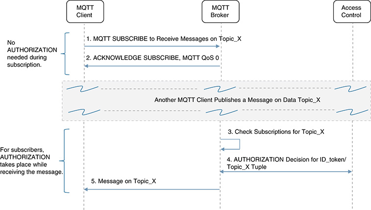
As in the authentication case, the access control server can also issue tokens to the MQTT clients during the authorization process. The tokens are usually issued with a certain lifetime to avoid the need to authorize every message individually, especially when they involve the same (client, topic) pair. However, performing authentication and authorization in two separate phases has some drawbacks, particularly in IoT. For instance, authorizing each read and write might be reasonable for sporadic communications between a client and the broker, but it might be unfeasible as the communication frequency increases, particularly when the clients run on batteries. It also introduces additional overheads that play against one of the central goals behind MQTT, to keep it simple and lightweight. With authentication and authorization following a two-phased approach, MQTT brokers need to manage different events at different moments in time, potentially handle tokens at different levels, and so on. Thus, to reduce complexity and the control plane traffic involved between MQTT clients and brokers, authentication and authorization are generally performed in a single step in IoT.
One approach that is being widely adopted is to use OAuth 2.0. It offers an authorization framework that was originally designed to allow a third party (a client) to access a resource that belongs to an owner, which is hosted by a server, without sharing the credentials with the client. This process typically involves four actors:
■ The resource owner (for example, a human being who has a mobile phone and a Facebook account)
■ The server (for example, a Facebook server), which has the resource (for example, the Facebook profile of the owner)
■ A third party or client (for example, a mobile app in the owner’s phone that needs authorization to post a new message on the Facebook profile of the owner)
■ An authorization server (for example, also managed by Facebook)
As mentioned previously, the goal is for the mobile app to get the authorization to post the message in Facebook without needing to know the owner’s credentials (the user and password in Facebook).
OAuth 2.0 solves this with a certain level of indirection. The client (mobile app) asks for a token to the authorization server (Facebook). Upon receiving the request, the authorization server (Facebook) asks for the credentials to the resource owner (the user needs to log in to Facebook using his or her credentials). If successful, the server (Facebook) sends an authorization token to the client (mobile app), which can use it to access the resource (the Facebook profile) on behalf of the owner.
This is the general operation of OAuth 2.0, but in the case of machine-to-machine (M2M) communications supported by MQTT, the number of actors involved in a publish workflow is typically reduced from four to three:
■ A publisher, which plays the role of the client (note that there is no resource owner in this case because there is no human intervention).
■ The broker, which plays the role of the server that has the resource (a message queue for topic x).
■ An authorization server.
The merits of OAuth 2.0 rest in the fact that the client does not need to know or hold the credentials, but this is not necessarily the case with MQTT. Industrial IoT (IIoT) is full of examples involving M2M scenarios in which the client and the resource owner are represented by the MQTT client. Despite this, popular implementations of MQTT, such as HiveMQ, are now supporting OAuth 2.0.
One reason is precisely because OAuth 2.0 enables authentication and authorization to be performed in a single transaction (see Figure 11-23). Recall that OAuth 2.0 is an authorization framework, so the token issued conveys the right to access a resource (for example, the permission to publish or read messages from a data topic). Authentication is explicitly involved in the process because, without successful authentication, the authorization token will not be granted. Other widely used solutions in the marketplace (such as LDAP) also offer single sign-on services and manage authentication and authorizations in a single transaction. However, the strength of OAuth 2.0 is that it is evolving to help secure and authorize access to devices in IoT. See, for example, the Authentication and Authorization for Constrained Environments (ACE) working group at IETF (draft-ietf-ace-oauth-authz-09).

As Figure 11-23 shows, the OAuth 2.0 authorization token is added to the password field of the MQTT CONNECT request that the client sends to the broker. The username can be set to a special string that allows the broker to parse the password as an authorization token. Upon receiving the CONNECT message, the broker can perform different checks, including validating the signature from the token and the authorization for the client (included in the scope claim of the token). The lifespan of the tokens is subject to an expiration time, and OAuth 2.0 can revoke any token previously issued.
Confidentiality in MQTT
In MQTT, data confidentiality between a client and the broker can be ensured with transport layer encryption (for example, supported by TLS). More precisely, TLS provides a secure communication channel between the client and the broker so that an eavesdropper cannot interpret the messages exchanged between the two, thereby preventing man-in-the-middle attacks. However, as mentioned previously, MQTT clients might not always have the capability to use TLS to secure their communications with a broker in the field. In other words, it cannot be presumed that the communications between an MQTT client and the broker will always be confidential in IoT. Obviously, any access tokens sent across an unsecure channel could be stolen and used.
Despite this, in many use cases, both the client and the broker can establish secure communications with the access control system before they talk to each other. For example, consider an unmanned drone that needs authorization to open an automatic door gate in an unmanned facility. The drone can get a token securely from the access control server while recharging batteries in its dock station (even before flying to the external facility). In the process, the drone and the access control server can exchange two randomly generated numbers, each of which is used as a key (OTP) to unlock the gate while entering and exiting the facility (the gate automatically closes in the meantime). The mechanism that opens the gate consists of two elements, an MQTT broker that communicates with third-party devices or things (the drone) and an elementary MQTT subscriber (the lock supported by a microcontroller). The MQTT broker has a secure communication channel with the access control server (for example, through a pre-provisioned link provided by IT). Although it is critical to have secure communications between the drone and the central access server, as well as between the gate and the central access server, the presence of legacy systems and constraints in the field makes it hard to guarantee TLS support everywhere. What cannot be assumed here is that the communication between the drone (an MQTT client) and the gate (MQTT broker) will support transport layer encryption. In this scenario, the access control server can proactively send the random keys and the ID of the drone to the broker, using the secure channel with the broker. When the drone arrives, even if an eavesdropper can see and steal the tokens and IDs, proof of possession combined with one-time use offers a reasonable solution when dealing with confidentiality issues in constrained environments. Some MQTT implementations are addressing these needs, combined with adequate plug-ins and extensions that are being developed to OAuth 2.0.
When it comes to data confidentiality between a publisher and it subscribers, TLS is clearly not sufficient. By default, the payloads in MQTT are transported unencrypted, so a compromised broker can actually see the data. To cope with this, encryption at the application layer can be used in the form of payload encryption (the following section provides detailed explanations while analyzing data integrity).
Integrity in MQTT
MQTT fundamentally provides two mechanisms that ensure the integrity of the data exchanged between a client and a broker. Again, the first is TLS because it allows for mutual validation of identities with X.509 certificates issued by a trusted authority (that is, the clients can also verify the identity of the broker). Although TLS grants secure communications and prevents man-in-the-middle attacks between clients and brokers, it does not detect message tampering or forgery at the application (MQTT) layer. To achieve this, the MQTT payloads can be digitally signed.
It is important to understand the difference between encrypting and digitally signing an MQTT payload, and to see its implications in terms of data integrity. Figures 11-24 and 11-25 show two different modes of payload encryption supported by MQTT. Figure 11-24 shows end-to-end encryption between the publisher and its subscribers. This means that the message is for the eyes of the subscribers only. In this case, the message broker operates as a data distributor because it cannot decrypt the payloads. Still, fields in the MQTT message sent by the client, such as the packet identifier, topic name, and QoS level, remain in clear text because the broker needs them to validate whether the client is authorized to publish in that topic and route the message to the subscribers with the corresponding QoS. Figure 11-25 illustrates the case in which a constrained sub-scriber is incapable of decrypting the messages. In that case, the messages are encrypted only between the publisher and the broker.
Note that application layer encryption cannot guarantee the integrity of the messages. For instance, a message broker represents a strategic point of control because a compromised broker can easily perform man-in-the-middle attacks. It can swap encrypted payloads between different publishers on the same topic, it can send encrypted payloads to another topic where the client is authorized to publish, and more. Clearly, using TLS will not solve this problem because these attacks exploit vulnerabilities at the application layer. Another issue is that a malicious broker can also carry out replay attacks. A replay attack compromises neither the confidentiality nor the availability of the messages because the broker is neither gaining access to secret information nor affecting the normal data flow. However, this is a breach to the integrity of the messaging system. Obviously, if the encryption mode shown in Figure 11-24 cannot ensure data integrity, the mode depicted in Figure 11-25 cannot, either.

Figure 11-24 End-to-End Encryption: Securing Application Data; Most Secure When Combined with Transport Layer Encryption (TLS)

Figure 11-25 Partial Encryption: Securing Application Data Writes; Usually Applied When Subscribers Are Very Elementary and Cannot Handle the Encryption
In general, payload encryption is used by constrained devices that cannot support TLS but do trust the broker. Encryption itself cannot guarantee the integrity of the data, but it can at least offer a basic level of confidentiality. The usual challenges related to encryption in protocols such as MQTT center on how to make encryption sufficiently lightweight for constrained devices and how to securely provision and distribute the keys to the MQTT clients.
As mentioned previously, the way to ensure data integrity is to combine TLS with digital signatures at the application layer. In principle, the payload can be signed hashing all the fields in an MQTT message (see Figure 11-26), but this is not recommended. The packet ID and QoS fields should be left out of the hash (that is, left out from the generation of the stamp in Figure 11-26). This is because a packet ID denotes a unique identifier for messages in the communication flow between a client and its broker. The packet ID is relevant only for QoS purposes, and clearly, the packet IDs between a publisher and a broker will differ from those between a broker and a subscriber because they are independent communication flows. Moreover, QoS can be downgraded because the QoS contract between a publisher and a broker might differ from the one between the broker and a subscriber. In general, including packet IDs and QoS will invalidate the signature stamp because the broker could change these under normal operating conditions. However, the topic name should remain unchanged. As such, signing the stamp and including the topic name is strongly recommended.

In addition to digital signatures, MQTT supports two other mechanisms for creating stamps (see Figure 11-26):
■ Checksums and hashes (based on CRC, MD5, SHAx, and so on)
■ Message Authentication Code (MAC) algorithms, including HMAC and CBC-MAC
These mechanisms can be used to generate stamps for the contents of an MQTT PUBLISH message, which can be directly validated by the subscribers. In summary, message integrity can be ensured by means of stamping payloads using digital signatures, checksums, hashes, or MACs.
Availability in MQTT
In terms of availability, MQTT offers three QoS levels that contribute to data protection:
■ QoS 0 (at most once, or “fire and forget”): This is the lowest QoS level offered by MQTT. It represents a best-effort approach, with no guarantee of delivery to the corresponding subscribers. In this case, messages are not persisted. The fact that the message is sent at most once means that if a subscriber gets disconnected in the middle of the message delivery, or the broker fails for any reason, or if a DoS attack occurs, the message will not be re-sent. The advantages of this QoS level are that it represents the easiest mode for exchanging data in MQTT and that it entails less overhead on the broker side.
■ QoS 1 (at least once): Unlike QoS 0, in which no acknowledgment takes place between the publisher and the broker, the broker acknowledges the receipt of the message. The publisher stores the message until it gets the ACK from the broker and starts a timer. If this times out, the publisher resends the message to the broker. Even if the broker has already delivered the message to its destinations, if it has not yet acknowledged this to the publisher, the publisher resends and the broker redelivers (this is why it is called at least once). At the application layer, the publisher sets the MQTT flag DUP to indicate to the final destinations (the subscribers) that the message is a duplicate. This is transparent to the broker because it resends all the duplicates received without checking. In summary, if an attack occurs and the reachability between clients and brokers gets compromised, the publishers will keep trying to resend until the message is delivered.
■ QoS 2 (exactly once): This offers the highest level of reliability. To ensure that only one message will be received by the subscribers, the communications between a sender (S) and a receiver (R) involve four messages. Note that the sender (S) can be either a publisher or a broker (Pub → B or B → Sub), and the receiver can be either a broker or a subscriber (Pub → B or B → Sub):
S → R — PUBLISH (message sent from the sender to the receiver). Sender S momentarily stores the message until it gets confirmation of successful reception from receiver R.
S ← R — PUBREC (Publish Received). Receiver R queues the message and stores a reference to the packet ID to avoid processing the same message twice. Upon receiving the PUBREC, sender S can discard the message stored locally because it knows the message is with receiver R.
S → R — PUBREL (Publish Release). When receiver R gets the PUBREL, it can discard the stored state and answer to sender S.
S ← R — PUBCOMP (Publish Complete). Sender S gets confirmation that the transaction is complete.
All messages sent with QoS levels 1 and 2 are queued and stored for offline clients with equal or higher QoS contracts (similar to the durability service DDS offers). Clearly, data persistence is needed to recover from broker restarts.
Nonrepudiation in MQTT
Nonrepudiation often is not needed in MQTT, but it can be ensured by using digital signatures. Note that although checksums, MAC, and hash algorithms can be used to create stamps and validate the integrity of a message at the receiving endpoint, they do not provide proof of authorship. If nonrepudiation is a must, the payload stamps must be signed using the private key of the MQTT publisher (see Figure 11-26). Subscribers can verify and validate the signature using the public key of the sender.
RabbitMQ
RabbitMQ is an open source message-queueing and broker system that supports a pub/sub model that is broadly used in the industry. It was originally created around the Advanced Message Queuing Protocol (AMQP), but over the years, it became a multiprotocol/multibroker system with plug-ins to MQTT, the Streaming Text Oriented Messaging Protocol (STOMP), and HTTP. The programming language chosen for implementing RabbitMQ is Erlang, given its capacity to support distributed systems that need to be prepared to manage large numbers of messages in a reliable way. Current distributions of RabbitMQ offer client libraries for the most popular programming languages, to facilitate the interface with the Erlang broker (Java, Python, Ruby, C, C++, Go, and so on).
Figure 11-27 illustrates the messaging model in RabbitMQ. In RabbitMQ, messages are handled differently than in MQTT because the messages transmitted by a client (a producer) are not sent to the broker’s queues directly. Instead, the messages are sent to an exchange, which is responsible for processing and routing the messages to the pertinent queues. Deciding which queue(s) should receive the message is based on bindings and routing keys. A binding represents a logical link between an exchange and queues. Bindings are created by an administrator and specify how an exchange should push the messages received from the publishers to the queues. Depending on its configuration, an exchange can push a message to a single queue or to several of them, or discard the message. This is determined by the exchange type chosen. As Figure 11-27 shows, a few exchange types are available in RabbitMQ: fanout, direct, topic, and headers (for simplicity, the headers type is not illustrated in the figure).
■ Fanout: A fanout exchange pushes messages to all the queues that are bound to it. It basically broadcasts the message to a predefined set of queues without offering much flexibility.
■ Direct: A direct exchange pushes messages to queues using a string identifier called a routing key. The routing key is an attribute that the producer inserts into the message header. A routing key adds extra semantics and operates as an address for the exchange. A direct exchange takes into account these semantics, which the exchange can use to decide how to route the message to the right queues with higher granularity. The message is routed only to the queues in which the routing key of the message exactly matches the binding key. To make this possible, a binding key with the same string identifier needs to be configured first. To illustrate the advantages of routing keys, consider a monitoring system that uses RabbitMQ within a node. This pub/sub system collects data from a number of sources (for example, from physical devices connected to the node, as well as from virtual instances running in the same node). In principle, all the messages received are broadcast to a number of consumers (for example, other instances running in the node, other nodes nearby, nodes in a data center, and so on). This can be implemented using a fanout exchange. However, receiving all messages unfiltered might be impractical for various subscribers. In addition, sending all the logging messages received could be unfeasible for the node (consider the case in which the node is a fog node in the field subject to constrained communications). One option is to filter the messages based on their criticality by using a direct exchange. For example, an administrator could configure a direct exchange in the fog node with two queues bound to it. The first one could be bound with the binding key CRITICAL, while the second one could have two binding keys, ALARM and ACTION. Whereas the first two keys are associated with the health of the elements being monitored, the third one has to do with cyber-physical actions in the field (for example, an actuator was activated). In this scenario, a message published to the exchange with the routing key CRITICAL will be routed to queue_1, while messages with the routing keys ALARM and ACTION will delivered to queue_2. The interesting point is that the broker will discard all other messages. This would not work with a fanout exchange because routing keys are simply ignored.
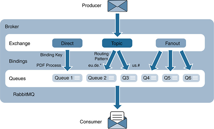
■ Topic: A topic exchange pushes messages to queues based on a routing key consisting of a list of strings delimited by dots (as in country.city.neighborhood.power_consumed). These denote data topics. As in the case of direct exchanges, a corresponding binding key needs to be defined with exactly the same format. The rationale behind a topic exchange is similar to a direct exchange, in the sense that all messages with a specific routing key will be pushed to the queues with a matching binding key. Those that do not match any queue are filtered. The main difference between topic and direct exchanges is that a topic exchange performs a wildcard match between the routing key received in the message sent by the publisher and the routing pattern specified in the binding. The use of wildcards substantially increases flexibility. For instance, an administrator could create the following bindings: i) queue_1 with the binding Spain.*.*.power_consumed; ii) queue_2 with the binding Spain.Barcelona.*.air_ quality; and iii) queue_3 with the binding Spain.Barcelona.Glorias.*. Clients subscribed to the first topic are interested in power consumption in Spain (regardless of the city and neighborhood). In the second binding, subscribers are interested in air quality monitoring in Barcelona. In the third, the interest is what happens in a particular neighborhood in Barcelona, Las Glorias. In this example, when a publisher sends a message with the routing key Spain.Barcelona.Glorias.power_consumed, the message is routed to queue_1 and queue_3 only.
■ Headers: A headers exchange pushes messages to queues using other attributes in the message header than the routing key. For the sake of simplicity, this is not shown in Figure 11-27.
RabbitMQ natively offers a multitenant server that is divided into logical units or groups called virtual hosts (vhosts). The main components offered by a RabbitMQ server, such as exchanges, bindings, queues, and users, are segmented into these logical groups to facilitate access control and administration. For instance, each client connection is bound to a specific vhost. This logical separation of resources also segments user permissions and policies because these are bound to the virtual hosts as well.
The basics of access control in RabbitMQ are summarized next. As in the case of MQTT, access control entails two validations, authentication and authorization. When a client connects to a RabbitMQ broker, it must explicitly specify the name of the vhost that it needs to connect to. The first level of control is enforced at this stage: The broker checks the client credentials and determines whether it has the right to access the virtual host (the authentication part). The main elements shown in Figure 11-27, such as exchanges, bindings, and queues, are named entities inside a specific virtual host. If the authorization is successful, the connection to the vhost is established. The second level of control is enforced when the client attempts to perform an operation on the resources of a vhost (the authorization part). More precisely, RabbitMQ basically offers three operations on a resource: configure, write, and read. The configure operation permits creating, deleting, or modifying a resource. A write operation corresponds to the action of publishing a message (that is, sending a message to the exchange offered by the vhost). The third and last operation is a read, which consists of retrieving messages from the queues on the vhost (the subscription part). Before a client can perform any operation on the resources offered by a vhost, the client must get the corresponding authorization.
In RabbitMQ, permissions are denoted as regular expressions within a tuple (configure, write, read) for each vhost individually. The permissions (configure, write, read) are granted for operations on all resources with names that match the regular expression. For instance, the regular expression ‘^$’ denotes an empty string, which is used to restrict permissions and forbid the client from performing any operation at all. As discussed in the case of MQTT, RabbitMQ can cache the outcomes of an access control check (for example, per connection). This is done to improve efficiency (for example, to avoid authorizing each operation individually). The counterpart is that policy changes, such as changes on the permissions of a client, are applied when the client reconnects. Some solutions can deal with this by forcing the client to reconnect.
It is worth mentioning that the binding of exchanges and queues in different vhosts is not allowed in RabbitMQ. In other words, two different vhosts cannot exchange messages unless it is solved externally by the application. For instance, an authorized client can connect to the two vhosts simultaneously. It can be a subscriber in one of the vhosts, consume the data that it needs and then republish into the second vhost. RabbitMQ offers clustering functions, so exchanging data across different vhosts is quite attractive when they belong to different clusters.
As mentioned previously, RabbitMQ is a multiprotocol system. Whereas protocols such as AMQP or STOMP handle vhosts, others (such as MQTT) do not. In general, MQTT connections are managed through a single RabbitMQ vhost, although there are workarounds to enable the connection of MQTT clients to specific vhosts without needing to modify the client library.
Authentication in RabbitMQ
The sequence diagrams and discussion on MQTT in this chapter are representative of the procedures and tools that developers and administrators have to protect data on the move. A significant part of what can be done in RabbitMQ follows the same reasoning, so the next sections will mainly focus on the peculiarities of data protection in RabbitMQ. For instance, RabbitMQ offers pluggable support for a number of Simple Authentication and Security Layer (SASL) mechanisms. Some are built into RabbitMQ (including PLAIN, AMQPLAIN, and RABBIT-CR-DEMO—see the following list); others are available as EXTERNAL plug-ins (developers can implement their own authentication mechanisms in a plug-in).
■ PLAIN: The default, equivalent to basic HTTP authentication
■ AMQPLAIN: Custom version of PLAIN, as defined by the AMQP standard
■ RABBIT-CR-DEMO: Custom challenge/response authentication
■ EXTERNAL: The capability to authenticate a client using its public certificate
By default, a RabbitMQ broker uses the PLAIN authentication method, and it is supported by all RabbitMQ clients. Client libraries also provide the means to specify the SASL configuration before attempting to connect to the message broker. More specifically, SASL allows a RabbitMQ client to negotiate the authentication method before the authentication process actually starts (see IETF RFC 4422). The flow is simple. The client initiates a SASL connection and the broker responds, suggesting possible authentication methods. Based on this, the client selects one method and starts the authentication phase. This is enabled by means of proper handlers, depending on the authentication mechanism selected.
In enterprise and other organizations, it is common to find other authentication services, such as an LDAP server or an RDBMS. RabbitMQ supports this type of external authentication. One aspect to be considered is that, in clustered settings, it is important to make sure that the same SASL configuration is applied across clusters. This is key to allowing clients to connect to other cluster nodes in a way that the same authentication mechanisms can be negotiated and used as in the original cluster. In IoT, this occurs often when the clients or brokers are mobile.
Authorization in RabbitMQ
After a client has been authenticated, the goal is to perform operations on the resources offered by a vhost. As mentioned previously, policies and permissions are defined and apply per vhost, and they can be stored and maintained either internally in the message broker or externally (for example, in an LDAP server enabled through the RabbitMQ LDAP plug-in). More specifically, permissions can be set and cleared per user, per vhost. Three main types of queries in RabbitMQ can be executed against an external access control server (for example, LDAP):
■ vhost_access_query: Users and permissions must be verified against vhosts that must exist in RabbitMQ. An LDAP server can define vhost entries that can be checked for available permissions and roles (tags) at runtime.
■ resource_access_query: These queries check whether a user has specific permissions (configure, read, or write) on a particular vhost to which the user has access (this can be checked by the vhost_access_query).
■ tag_queries: These queries specify the roles (tags) associated with a particular user (such as manager or administrator).
As mentioned previously, RabbitMQ offers a variety of plug-ins to perform authentication and authorization through an external access control system. Clients with accounts managed by those systems usually need to exist in RabbitMQ’s internal database, too, although RabbitMQ does not need to know or maintain the credentials and policies managed by the external systems. This is because, even after getting authorization from an external system, subsequent authorization checks might be performed against RabbitMQ’s internal database.
RabbitMQ also supports topic authorization for topic exchanges. This feature targets protocols such as MQTT and STOMP, which were designed around data topics. This offers an additional layer of checks for publishers because they will go through both the basic resource permissions and topic-based routing checks. Note that topic authorization is not invoked if the basic authorization is denied (for example, when the client is not even authorized to write on a given vhost). Overall, the interesting point with RabbitMQ is that the routing keys published to a topic exchange are taken into account during authorization checks and are matched against regular expressions to decide whether a message should be routed to a queue. Moreover, topic authorizations also can be applied to consumers.
In some cases, it is useful for subscribers to know the ID of the publisher. Hence, it is important to ensure that the ID of the sender can be validated (for example, by ensuring the integrity of the message). This attribute is set by the publisher; if it is not explicitly set, the publisher’s ID remains private. The example in Figure 11-28 shows a snippet in which an AMQP message will be routed by a fanout exchange only if the client publishing the message is motion_sensor_1. As described in the section “Nonrepudiation in RabbitMQ,” while examining the nonrepudiation mechanisms RabbitMQ offers, this identity should be taken as indicative and can help receivers process the message, assuming that it is operating in a trusted and noncompromised environment. RabbitMQ lacks built-in mechanisms to provide nonrepudiation.
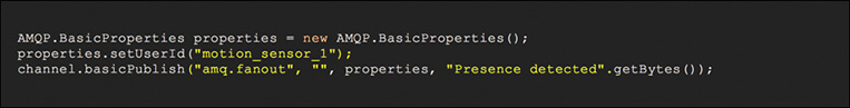
Confidentiality in RabbitMQ
In RabbitMQ, data confidentiality between a client and the broker can be ensured with transport layer encryption (TLS). When it comes to data confidentiality end to end (that is, between a publisher and it subscribers), TLS is clearly not enough: A compromised broker can see the contents of the messages. The option is to use payload encryption. This should be combined with TLS whenever possible. As discussed in the section “Message Queuing Telemetry Transport Protocol,” there is often a trade-off between security and the computational resources required at the endpoints, and this is particularly relevant in IoT.
Integrity in RabbitMQ
As in the case of MQTT, the problem of ensuring message integrity can be split into two parts: between a client and the broker, and between a client and its subscribers. The first part can be tackled using TLS because this avoids eavesdropping and man-in-the-middle attacks. Although the secure transport mechanisms supported by RabbitMQ can guarantee the integrity of the messages between a client and the server (note that this encompasses both client/broker and broker/broker communications), guaranteeing the integrity of the messages end to end across brokers and various protocols (MQTT, AMQP, STOMP, and so on) is beyond the scope of RabbitMQ.
The challenge for data integrity lies in the fact that the brokers in the data path can be compromised. This issue can be addressed by properly protecting the infrastructure that hosts the broker instances. Chapter 14, “Smart Cities,” covers this as part of the security measures required to protect the platform itself. Application designers who rely on RabbitMQ as a multiprotocol/multitenant message distribution system can leverage its MQTT plug-in for data topics where message integrity end to end is a must.
Availability in RabbitMQ
Figure 11-29 depicts the data durability and persistence features offered by RabbitMQ. These were originally designed to cope with server failures and restarts, as well as the need to get the messages back to the right queues when the server is back. However, they are also key in protecting data during DoS attacks or any attempt to compromise data availability.
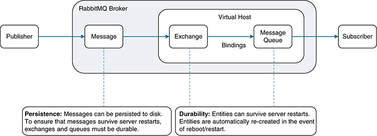
If a RabbitMQ server restarts, only persistent messages are re-created in the queues that were declared durable. By default, if a RabbitMQ server goes down, all the messages that were queued are lost. To ensure that a message will survive after these types of anomalies, the following functions need to be explicitly configured:
■ The message needs to be declared as persistent.
■ The message needs to be published to a durable exchange.
■ The message needs to be pushed to a durable queue.
Other Considerations Related to Data Availability in RabbitMQ
RabbitMQ and the operating system where it is running provide elements that can be configured to improve both performance and availability. This depends on whether the RabbitMQ instance is running in a fog node in the field, in a blade in a data center, and so on. For instance, configuration tweaks vary between a low-end fog node (for example, a Raspberry Pi) and a full-fledged industrial PC (although this obviously depends on the number of messages that need to be processed per second and the storage and memory requirements of the services offered). In RabbitMQ, several features can be tuned and have either a direct or an indirect impact on data availability:
■ Heartbeats in AMQP and STOMP, and keepalives in MQTT.
■ Interfaces and ports. The default configuration of RabbitMQ is to listen on port 5672, and this applies to all available interfaces in the hosting device. RabbitMQ manages dual stacks (IPv4 and IPv6). Regarding access to specific ports, it is important to check whether SELinux, firewalls, or similar tools might be preventing RabbitMQ from binding to a given port. With current implementations, the following ports need to be open:
■ 15675: MQTT-over-WebSockets clients (only if the Web MQTT plug-in is needed)
■ 1883, 8883: MQTT clients with and without TLS (if the MQTT plug-in is needed)
■ 5672, 5671: AMQP clients with and without TLS
■ 15674: STOMP-over-WebSockets clients (only if the Web STOMP plug-in is needed)
■ 61613, 61614: STOMP clients with and without TLS (only if the STOMP plug-in is needed)
■ 25672: Erlang distribution for internode and CLI tools communication
■ 15672: HTTP API clients and rabbitmqadmin (only if the management plug-in is enabled)
■ 4369: Peer discovery service used by RabbitMQ and CLI tools
■ TLS.
■ TCP socket settings (for example, buffer sizes).
■ Kernel TCP settings (for example, TCP keepalives).
■ Hostnames and DNS.
In IoT, the spectrum of use cases is broad. Some brokers might end up managing messages from a large number of clients but generate relatively low traffic volume; others might be connected to a single publisher and a few subscribers, but have a very high traffic volume. Depending on the use case, RabbitMQ configuration should be optimized. For instance, in some cases, the maximum number of clients that a broker can concurrently support might be more important than the total throughput to manage the traffic volume. Several factors can impact the number of concurrent connections that a node can handle:
■ Maximum number of open file handles (including sockets and the kernel’s resource limits)
■ Amount of CPU resources used by each connection nominally
■ Amount of RAM used by each connection nominally
■ Amount of disk used by each connection nominally (when persistence applies)
■ Maximum number of Erlang processes allowed
Nonrepudiation in RabbitMQ
The core security functions in RabbitMQ apply between the client and the server. Using TLS with X.509 certificates issued by a trusted authority supports mutual validation of identities during the authentication phase. However, as a transport protocol, TLS provides no proof of authorship for the payloads at the application layer. An attacker capable of compromising a client application can exploit an already established TLS session with a broker and forge and publish messages on behalf of the application owner. Some recent works propose extensions to endow TLS with nonrepudiation mechanisms, such as TLS-N (nonrepudiation over TLS; see https://tls-n.org); however, these extensions have not reached RabbitMQ at the time of this writing.
Again, nonrepudiation is ensured by using digital signatures at the application layer. The combination of TLS and signed application data provides nonrepudiation means between a client and a broker, but it does not truly solve the problem between publishers and subscribers—unless the integrity of the messages can be guaranteed as well. Clearly, the integrity of a message received by a subscriber cannot be ensured by simply chaining and stitching TLS sessions on a data path (publisher → broker → broker … → broker → subscriber) because a compromised broker can forge a message with a payload duly signed at the application layer. A binding is needed with the message distribution protocol, such as the payload stamps using MQTT header information shown previously in Figure 11-26. This requires support from the protocol, but RabbitMQ does not provide this natively.
In summary, if the objective is to ensure nonrepudiation between the clients and the server, then TLS plus digitally signed payloads will suffice. If the application actually requires nonrepudiation proofs end to end, then the MQTT plug-in for those specific data topics should work.
Example: Orchestrated Security on RabbitMQ at the Fog Node Level
Now that we have covered the fundamental aspects of two widely adopted open source message brokers (MQTT and RabbitMQ), we analyze how to protect data on the move by means of orchestrated security. We focus on a concrete example, in which we first create a new vhost in a RabbitMQ instance running in a fog node and then add one publisher and a subscriber; finally, we authorize the exchange of data across two different tenants at the fog node level. All these actions will be secured and carried out through automated transactions as a result of service orchestration. The use cases considered here are just a preamble of the ones that Part IV examines in detail.
As a reference model, consider the architecture shown in Figure 11-30. This is just a variant of the architectures analyzed in Chapters 6, 8, and 13. It is an NFV-centric architecture, with ETSI MANO as the core management and orchestration system. As illustrated in the catalog of services, it offers a portfolio of SDN controllers and components that can be deployed as concrete instances for different services, depending on the needs of the IoT use cases addressed. At this stage, we focus on just the main components needed to orchestrate security around a message broker (RabbitMQ, in this specific example); Figure 11-30 highlights these components. For detailed descriptions of each component in this architecture and how to secure the platform itself, refer to Chapter 13.

The platform is assumed to support multitenancy. For example, a tenant could be a city department, such as the energy, public lighting, or traffic department. These tenants share the same resource fabric—that is, the same fog, network, and back-end infrastructure—and they can deploy and manage the lifecycle of their services concurrently in their virtual slices across the underlying infrastructure. Each tenant can have multiple users. Even if those users belong to the same tenant, they can have different roles, such as tenant admin, tenant operator, and tenant viewer. These roles are captured in the form of access privileges and the right (or not) to perform specific actions on the following components:
■ The infrastructure
■ The service catalogs
■ The applications
■ Their service instances
■ The data they manage
In other words, these roles are bound to concrete authorizations and access control to the physical and virtual infrastructure, the applications, and the data they generate. For instance, a tenant admin can do anything that is allowed on the platform on behalf of the organization (tenant) that he or she represents. More specifically, an administrator can create, modify, and delete users for that tenant. The admin can create new services and change policies (although this is restricted to the reach of the tenant’s privileges), manage entire CRUD actions associated with the lifecycle of a service (such as deploy or remove a set of instances for a specific service), and more. The role of a tenant operator is more restricted than a tenant administrator. An operator can manage CRUD actions around service instances but, for example, cannot create new services or new users under the same realm, new data topics, and so on. All these actions require tenant admin privileges. A tenant viewer is even more restricted. The viewer can see, monitor, and create tickets for different alarms and elements of an IoT service under the control of a tenant, but cannot modify any of the instances deployed. All these actions can be captured in the form of authorization profiles that can be enforced through traditional RBAC mechanisms. Figure 11-30 illustrates these different tenants and the users representing them. The architecture depicts the fact that the management and data plane UIs are separated because these typically require different skill sets and cover different needs. For instance, the management UI is in charge of service lifecycle management, whereas the data plane UIs focus on data analysis and BI for specific use/business cases.
The scenario assumes that the back end shown in the figure is already deployed. It also assumes that there is a fog node deployed in the field that initially has three TEEs running:
The fog agent running in TEE0. This represents a VM that hosts RabbitMQ and other instances, such as Cisco ConfD and local access control. This VM was instantiated during day-0 configurations. The VM instance belongs to a tenant admin that is in charge of administering the whole platform (for example, this user is with the IT department of the city).
A virtual switch/router in TEE1 (for example, a Cisco CSR1000v) running in another VM. In this case, both TEE0 and TEE1 could potentially belong to and be administrated by the same tenant (for example, the city’s IT department).
An application running in TEE2 that receives and processes video feeds from a PoE video camera connected to the fog node in a third VM. This TEE could belong to another city department or tenant (for example, the safety department or the police department).
An application running in TEE3 will be deployed later (as part of the orchestration). This application collects information from different sensors connected to the fog node in a fourth VM. The VM could belong to a third department or tenant (for example, environmental control).
In this framework, we start with the objectives related to data protection—that is, we look at what a tenant administrator needs to do. The following list enumerates the actions required of the tenant administrator:
Securely create a new vhost and a data topic that can be used by the RabbitMQ instance running in the fog node.
Securely create a new instance in the fog node (TEE3), and make sure that the application running in TEE3 can push relevant data to the newly created data topic (that is, configure the application in TEE3 as a publisher in that vhost/data topic). The endpoints (things) that send data to the application running on TEE3 are assumed to be already deployed and also assumed to have been onboarded securely using the mechanisms described in Chapter 9. The deployment of TEE3 will be done according to the guidelines described in Chapters 7 and 13 and the use cases covered in Part IV. The focus here is on authorizing the application on TEE3 to push data to a new vhost/data topic on a RabbitMQ instance that is running on another VM within the fog node.
Make sure that the importer/exporter application running in the agent (TEE0) can pull data from that vhost/data topic in RabbitMQ (that is, configure the importer/exporter application in TEE0 as a subscriber of the newly created vhost/data topic) and push the data received to a historian database instantiated in TEE0. The role of the importer/exporter can be as simple as being a parser of the messages received from RabbitMQ (for example, extract the payloads from MQTT and AMQP) and pushing them as unstructured data to the database. However, let’s assume that, in this example, the model followed is ETL because the historian database handles structured data. Thus, the importer/exporter process can minimally structure the data in a way that can be stored in the database. The data pushed to the historian database can be immediately consumed by applications running either within or outside the fog node, without requiring schema-on-read transformations in real time that might be too demanding for some fog nodes. Note that, when streaming analytics are also needed in the fog node, the streaming process also can be declared (configured) as a subscriber for the newly created vhost/data topic in RabbitMQ. This enables RabbitMQ to feed both a historian database and a streaming process for running different types of analytics concurrently inside the fog node—similar to the hot and cold paths in Figure 11-15, although at a very different scale. For the sake of simplicity, this example concentrates on creating just one subscriber for RabbitMQ (the importer/exporter process).
Ensure that an analytics process running in TEE0 can query the historian database and analyze the data created through the new vhost/data topic.
Authorize data sharing across applications that belong to different tenants within the fog node. In practice, the richest use cases arise when data produced by one tenant can be consumed by others, thereby enabling the creation of data workflows that add business value across various teams and departments within and beyond an organization. Note that one of the central aspects of fog computing is its capability to analyze data, make decisions locally, and operate autonomously (that is, even without backhaul connectivity to back-end applications). Hence, the objective in this case is to allow two applications from different tenants running inside the fog node to share data in a secure and mediated way. The term mediated refers to the fact that applications owned by different tenants are not authorized to exchange data directly. Instead, they do it indirectly through the database and the RabbitMQ instance running in the fog agent in TEE0 (this is illustrated in detail later, in Figure 11-32). In the example, the objective is for data produced by the sensor application running in TEE3 to be consumed by the application running in TEE2. The use case seeks to trigger video streaming to a control room in the city, based on events detected by the application running in TEE3 (what we call event-based video). Note that event-based video use cases are covered in detail in Part IV. In this chapter, the focus is on protecting the data distribution part only. When we mentioned “secure and mediated,” the term secure refers to the following:
■ The tenants’ users need to be authenticated.
■ The exchange of data needs to be authorized.
■ The communication channel must be secure.
■ The fog node needs to ensure that the authentication and authorization steps can be checked and enforced locally (even if the fog node loses connectivity with a centralized access control system).
Now that we have covered the what, we can focus on the how and outline the orchestration and automated transactions needed to achieve the goals previously described—in particular, to protect the exchange of data in RabbitMQ. This is explained in the eight steps of the orchestrated transaction illustrated in Figure 11-30:
The tenant administrator (in the figure, the person at the top right) logs in to the management dashboard using her credentials and enters the parameters required to deploy and configure the service (the name of the vhost to be created, the application that needs to be instantiated in TEE3, the fog node where the service needs to be deployed, and so on). Then she triggers the instantiation of a service that will create a new vhost/data topic and cover all the items from A to E, enumerated previously, in a single (orchestrated) transaction.
The actions performed in the management dashboard translate into API calls to the back-end platform. The API calls can be protected by means of secure transport (such as TLS) between the dashboard front end and the dashboard back end.
Assume that, in this example, RabbitMQ uses LDAP and access control is centralized. Although LDAP can be perceived as a legacy technology and is not necessarily a good match for many IoT applications, it is important to understand that it is widely used in practice; many examples and use cases in real-life environments demand integration with LDAP servers. Going back to the example in Figure 11-30, this step actually creates the new vhost/topic in LDAP. The creation involves defining permissions for the users authorized to perform operations (configure, write, or read) on the resources the vhost offers. For instance, the importer/exporter supports a RabbitMQ client, and a user associated with this module needs to be authorized in LDAP to read from the vhost. Note that the creation of a new vhost/topic in LDAP does not mean that the vhost is created in RabbitMQ. It has been created only in LDAP; the vhost still needs with be configured in the desired instance(s) of RabbitMQ. Also note that a city might have thousands of fog nodes installed, each of which might have an agent with a RabbitMQ broker (see TEE0 in Figure 11-30). As a result, thousands of RabbitMQ instances might be deployed in the field. The orchestrated transaction described herein configures only the RabbitMQ instances that are required by the service that needs to be instantiated (that is, only those that are actually involved in the service). This could entail a single fog node, a subset of fog nodes in the city, or the entire installed base of fog nodes in the city. The back-end system can handle this selectively and perform the instantiations in the nodes required (only those that the tenant administrator selected and that will run instances of the service).
An asynchronous process can update the authentication and authorization process running locally in TEE0 in the fog agent. This synchronizes a centralized access control server with the distributed access control instances that will handle the authorizations locally in the fog nodes. In particular, it updates the vhost list in the access control instance in TEE0 by adding a new entry for the vhost created in LDAP in step 3. The access control process in TEE0 can be embodied in different ways, such as through a local database, a tokens database, or an LDAP replica. To keep the example simple, assume here that the update process is carried out by replication, using a lightweight LDAP replica in TEE0. Note that the tree that is replicated in this case is not the one for the entire city council. As mentioned previously, having local means to authenticate and authorize data exchanges at the fog node level is key, especially when it might not be possible to guarantee reliable connectivity to a centralized LDAP server in the back end at all times. In particular, if the replication fails because of lack of connectivity, the system keeps retrying until the replication is made. Secure replication is assumed in this case (for example, using TLS transport). Completion of this step guarantees that the vhost/data topic is now available in the access control processes running in TEE0 in the fog node, but note that the back-end system has not yet configured RabbitMQ.
When the distributed access control is ready, the orchestration system starts the configuration of RabbitMQ and other elements that are required to meet the objectives described previously (A–E).
A secure NETCONF/SSH connection is established with the fog node agent using Cisco ConfD, and the RabbitMQ broker running in the same VM is exposed as a configurable device to the orchestration system. The corresponding vhost/topic in RabbitMQ can be configured using a standardized data modeling language (YANG) and the new configuration is pushed over a standardized interface (NETCONF).
The vhost/topic is configured in RabbitMQ. The orchestration system then instantiates the application in TEE3, connects the VM’s I/O to start collecting data from the sensors southbound of the fog node, and configures the application as a RabbitMQ publisher. Figure 11-31 shows a snippet of the YANG model used for deploying this sensor application. The focus here is on the security related to RabbitMQ itself. Hence, when the VM has fully started, the publisher needs to authenticate and get authorization to publish data on the new vhost. As Figure 11-31 shows, the rmqvhost (the name of the vhost that was created) is one of the parameters that the administrator needs to enter in the dashboard (see step 1, before the orchestrated transaction actually starts). The authentication occurs as follows. The application in TEE3 establishes a TLS connection with the RabbitMQ broker in TEE0. The SASL authentication uses the lightweight LDAP replica running locally in TEE0 in the fog node, which can provide both authentication of the user credentials (see the leafs rmquser and rmqpassword in Figure 11-31) and authorization to access the desired resource (the vhost/topic). As mentioned previously, the importer/exporter embeds a RabbitMQ client that was granted permissions in LDAP before (and the local replica as well), allowing it to connect to and read from the vhost. The importer/exporter has a flexible microservice architecture that can be configured at runtime, so the subscription of the importer/exporter to the corresponding vhost also occurs in this step (on top of TLS).
Figure 11-32 shows that, as data starts to be stored in the historian database, the analytics process running in TEE0 can query the historian database and analyze the data associated with the new vhost/data topic. Whenever a predefined event is detected, the importer/exporter can create a notification message and publish it to another vhost/queue (previously created) on which the video application is declared as a subscriber. Upon receiving the notification from the broker, the video feeds collected by TEE2 can be streamed (live and buffered videos) to a central control room managed by a specific city department.
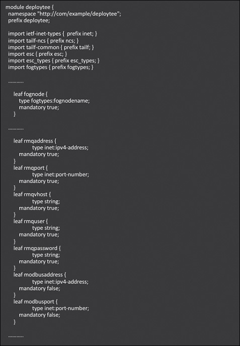
Figure 11-31 YANG Model for Deploying a New TEE, Including RabbitMQ and Modbus Port Configurations in a Fog Node
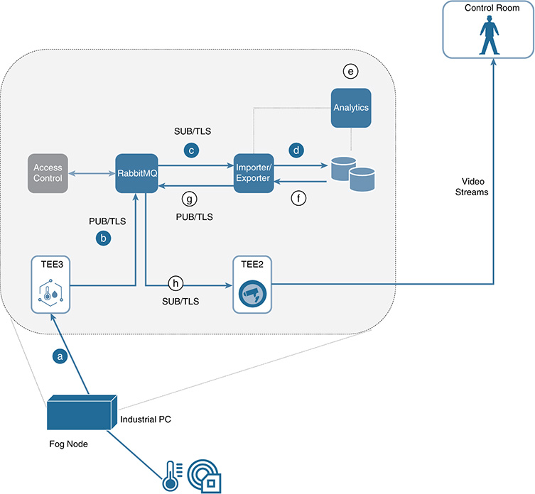
Cisco Edge and Fog Processing Module (EFM)
EFM was designed to enable computing capabilities in highly distributed environments with a strong focus on fog computing and IoT. EFM facilitates pushing data processes to the network edge, with the aim of accomplishing the following:
■ Connecting to a broad range of devices and sensors in the field
■ Performing analysis and applying rules and logic on both data in motion and data at rest
This approach supports not only local decisions and actions, but also data filtering before transmission to higher levels in the fog to cloud continuum. As shown in Figure 11-33, EFM has a powerful data flow editor that enables the visual programming of data pipelines using drag-and-drop functions. It also offers customizable tools that enable data visualization and analysis.

The technology behind EFM is the open source Distributed Services Architecture (DSA), which consists of the following elements:
■ Node: In DSA, a node is a general term used to reference the different components connected by DSA. For instance, a node can be a broker, a DSLink, or a folder containing other nodes; it can also represent other entities, such as actions, a metric, or metadata (attributes).
■ A broker: This element is responsible for routing and delivering data to its destination(s). DSA offers a multibroker system (that is, messages can traverse several broker hops before they reach their destination). Because brokers control the data flows, the operation of other elements in the DSA architecture strongly depends on the decisions made at the broker level (including security enforcement).
■ DSLinks: These elements are used to generate, write, and deal with data. A DSLink connects to a message broker and can also subscribe to receive data. Different sensors and actuators require the use of different DSLinks because a DSLink is ultimately the element that interacts with the data producers and consumers (see Figure 11-34).

■ Actions: An action basically represents a command, which can be invoked to affect an entity in DSA. For instance, an action could be used to create a node, set a data/metric value, and so on. Actions can be applied on brokers, DSLinks, and other nodes.
■ Metric: This is a key/value pair, in which the value can be any of the data types supported in DSA.
■ Data nodes: These nodes enable storing data on the server that hosts the broker.
■ Attribute: This is metadata denoted as a key/value pair.
To illustrate some of the elements previously described, consider the example in Figure 11-34. Computation is divided into three segments: at the edge, at higher layers in a fog hierarchy, and in regional data centers. The example depicts data flows in the oil and gas space, where two different families of sensors are used (shown on the left): distributed temperature sensors and distributed acoustic sensors. In the first case, sensors take temperature samples along a fiber cable that is 30 km long; they can produce 30,000 temperate readings per second. Acoustic sensors, on the other hand, record sound waves along the same cable and typically produce high data volumes at a very high rate.
In this scenario, the first step that needs to be solved is collecting the data. As mentioned previously, EFM was designed around DSA, so the data acquisition part involves DSLinks. Figure 11-34 shows these as the temperature and flow links on the left, for the temperature and acoustic sensors, respectively. These DSLinks basically operate as drivers or connectors for the different families of sensors (see Figures 11-9 and 11-10). The raw data gathered from the sensors can be processed, sampled, filtered, and even transformed into semistructured or structured data, depending on the needs. After processing, the data is sent to the first level of brokers, which route the messages according to the flows defined with the flow editor in Figure 11-33.
As Figure 11-34 shows, DSLinks are also needed to connect subscribers to the brokers, including processes to perform streaming analytics, historian analytics, or data storage in a data lake. The whole data processing flow is simplified in the figure, but EFM creates instances that can run in different chassis, connects them at a pub/sub level, and embeds analysis on a time-series as part of the messages flows. It also creates not only hot and cold paths for data analysis, but also collects raw data that can be sent for further processing to a data warehouse, a data lake, or other EFM instances. EFM itself embeds a historian database that can manage high data volumes at high velocity.
The security functions in EFM are built around the ones offered by DSA. Permissions in DSA determine the capabilities of users, DSLinks, and brokers. In DSA, the notion of upstream and downstream connections is relevant and has implications while configuring permissions either on multiple servers or on multiple brokers within the same server. A downstream entity typically requests for permission, and an upstream entity grants or refuses permission. In the DSA framework, a broker is always considered to be upstream from its DSLinks, although a given broker can be either upstream or downstream from other brokers. These permissions involve two distinctive concepts (at least, when comparing DSA with MQTT and RabbitMQ): tokens and quarantined entities (for example, broker and DSLinks).
Tokens are necessary when brokers are configured in such a way that they limit the connection of unknown DSLinks (the following section covers the use of tokens to control which entities are held in quarantine). Note that tokens are never required for DSLinks that this broker manages directly. This occurs when the DSLink is maintained by the broker, which means that a token for the DSLink is automatically generated. Tokens can be created either programmatically or manually. Either a broker or a DSLink can create tokens. Tokens are created subject to certain parameters, including time range, a string that indicates a time bound, up to when the token remains valid; count, an integer that limits how many times a token can be used; and managed, a Boolean value meaning that the expiration or removal of the token causes all the DSLinks connected via the token to be removed from the broker.
The other distinctive aspect of EFM is the notion of quarantined entities, a concept that was developed by DSA. Quarantine can be enabled on a broker so that any downstream broker or DSLink without an authorized token is kept in quarantine. An important aspect is that quarantined elements can work only as a responder. Other EFM elements can read (subscribe to) nodes that are in quarantine, but nodes in quarantine state cannot access other nodes in the pub/sub system. To remove a node from quarantine, users can either authorize the node or refuse its access and remove it from the system. Fully trusted environments can disable the quarantine process, thereby authorizing entities to connect to a broker without requiring a token for approval.
It is worth mentioning that EFM supports LDAP as well as local means of managing user/password credentials. In the CIA triad, DSA is mainly focused on secure communications between DSLinks and the brokers. External means are needed to offer confidentiality, integrity, availability, and nonrepudiation end to end, although the quarantine model supported by EFM can substantially increase the overall data availability.
Data Virtualization: Enabling Single Query Models in IoT
EFM can be combined with data virtualization techniques to expand the capabilities to integrate, exploit, and use data at rest. Data virtualization is a well-known technology that provides a unified view of data supplied by different data sources without needing to replicate them. As Figure 11-35 shows, data virtualization allows the integration of data from sources that are of different natures, that sit in different locations, and that are stored in different formats (structured, semistructured, or completely unstructured). In other words, it allows data to be used and consumed directly from its source and in its original format. This is achieved by means of an abstraction layer that allows consuming applications (such as analytics and BI tools) to perceive the data as a unified and integrated data pool. This is particularly relevant when enterprise applications and reporting tools are already tailored to use certain interfaces, or when they expect specific data schemas, query paradigms, or security measures, because these can remain as they are for consuming applications.
Data virtualization is fundamentally a data management tool that allows consuming applications to query, retrieve, and handle data without needing to know how data is formatted at the source or even where it is physically located. To solve the mismatch between the data formats and semantics at the source and the final consumers, various transformation techniques are used in the industry. In general, data virtualization solutions are bidirectional, which means that they also support pushing data to the source repositories.
It is worth highlighting the difference in the ETL and ELT models covered before in this chapter. Unlike ETL and ELT, which typically “move” data from their source locations to data warehouses or data lakes, data virtualization techniques keep the data in their original locations and grant access to the source systems to manipulate data in real time or near–real time. These abstractions and the logical decoupling offered by data virtualization enable a single query to be issued by a consuming application, which can retrieve and combine data from multiple sources. This is particularly relevant in the IoT arena. For instance, the data sources could be databases instantiated in fog nodes in the field. These fog nodes could have different computing capabilities and form factors, making the use of different kinds of database solutions and data storage techniques imperative, depending on the computational budget. The number of fog nodes deployed in the field (for example, in urban spaces in a city) could be large. In this scenario, a consuming application can issue a single query and, thanks to data virtualization, can retrieve data from a potentially large set of fog nodes of various shapes and sizes. This approach facilitates the development of geodistributed analytics by combining local data analysis in fog nodes with regional and centralized analysis, regardless of the data source structure, data schemas, and locations.
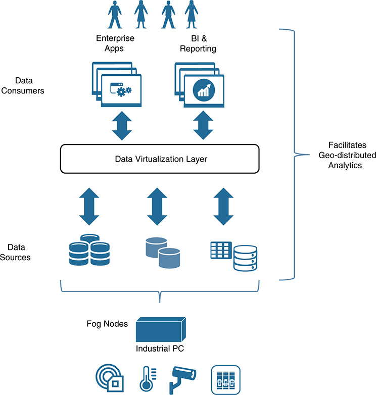
In terms of security, this model is feasible only if the data sources and consumers can establish trust and protect the data at rest, in use, and on the move. Data in motion can be protected by means of a secure transport layer protocol between communicating entities, such as TLS, combined with X.509 certificates (as described in Chapter 7, “Securing SDN and NFV Environments”). For data at rest and data in use, the protection mechanisms center on securing the platform itself (for example, securing the fog nodes, the back-end servers, the applications they run, and the APIs); Chapter 13 covers this. Token-based quarantine mechanisms, such as the ones provided by EFM and DSA, also contribute to protect the data until trust is established with quarantined entities.
Protecting Management Plane Data in IoT
After you analyze how to protect the data plane, the next step is to protect the data produced and used by both the control and management planes. Actually, best practices indicate that the order should be exactly the opposite: First, we should set the basis to protect the control and management planes; then the platform is ready to start provisioning and securing services for the targeted use cases (that is, the data plane part). It is unthinkable to seek to orchestrate and automate security for IoT use cases if the management plane responsible for these functions is not secure itself. We covered the data plane first because it is easier to explain and also because the approach followed in previous sections of this chapter is applicable (at least, partially). More precisely, the protection mechanisms applied to data associated with the management plane can be split into two categories: those that target the security of management data on the move and those that target the protection of data either at rest or in use.
For the first category, the concrete examples covered for user authentication and authorization, along with the mechanisms to ensure the data confidentiality, integrity, availability, and nonrepudiation of messages, are equally applicable to the management plane. The protocols used might vary and the endpoints might have a different nature, but the principles for protecting data on the move remain fundamentally the same. For example, consider the orchestration use case covered in Figure 11-30. Automated management operations are commanded through data exchanged between management endpoints whose communications are secured (for example, using TLS and X.509 certificates, NETCONF/SSH between Cisco NSO and the fog node, and so on). The users and entities that exchange management data need to be authenticated and authorized to perform orchestrated transactions. For example, a user with a tenant operator role has the right to instantiate a service under the tenant’s realm, whereas a user under the role of tenant viewer does not. It is worth noting that some of brokers/protocols covered previously (such as MQTT and RabbitMQ) are also used at the management plane. For instance, VIMs such as OpenStack run RabbitMQ for internal purposes. Best practices recommend firmly separating the data exchanged at the data plane level from the data transported by the management plane. In general, when it comes to data on the move, different interfaces, networks, and protocols are usually used, thereby segmenting the different data flows. Depending on the management needs, features such as confidentiality and nonrepudiation tend to be less prominent in practice than data integrity and data availability. Whereas data integrity and data availability are a “must have” for operational data on the move, confidentiality and nonrepudiation are merely “nice to have” in some cases (although this is rapidly changing with the broader attack surface in IoT).
The second category, the analysis of mechanisms to protect management data at rest and in use, has roots in the protection of the platform itself, as addressed in Chapter 13.
Protecting Control Plane Data
In IoT, the data generated by the control plane is mainly associated with Layer 2 switching and Layer 3 routing processes, the data required to control a number of non-IP-based protocols (such as serial and bus communication protocols), the data produced by signaling elements and signaling protocols, and the data handled by SDN controllers. Special intricacies depend on whether the environment considered is wired or wireless, whether it is subject to low power constraints, and so on. For instance, protecting data associated with a control plane instance embodied in a microcontroller in a luminaire inside a building differs substantially from securing the data produced by an MPLS control plane involving, for example, virtual switch/router instances hosted by fog nodes (see TEE1 in Figure 11-30). Clearly, detailing all the mechanisms available for protecting the data produced and used by a wide spectrum of protocols and control planes in IoT merits a book of its own.
However, the principles we covered previously remain exactly the same. As described in Chapter 9, at the control plane level, devices should go through strict access control and be securely onboarded and identified through proper authentication. Any control plane operation, ranging from generating a message carrying an event, up to distributing routing data, needs to be controlled and authorized. In addition to the mechanisms covered in Chapter 9 related to identity management, authentication, and authorization applied to the control plane, the principles in the CIA triad for protecting control plane data also remain the same. The specific mechanisms that can be applied in one control plane are conditioned by the device and communication constraints and the specificities of the protocols used; however, the principles for protecting the data are the same.
In this book, the focus is on securing IoT use cases powered by NFV management and orchestration and SDN controllers. Therefore, when it comes to protecting control plane data, the targets are to secure two types of data:
■ Data associated with the control plane protocols used by an NFV orchestration system
■ Data associated with the SDN controllers
Chapter 13 covers these aspects. Our approach uses the platform as a use case, and we apply both the protection mechanisms developed in Chapters 7 and 9 and the ones previously outlined in this chapter.
Considerations When Planning for Data Protection
Data protection mechanisms can be classified into two categories, proactive and reactive mechanisms. The first category deals with the planning and security measures that are needed to detect threats and prepare an IoT platform to protect the data against possible attacks. The second category has to do with the planning and countermeasures employed to repel an attack to the data.
Proactive mechanisms require a deep understanding of the aspects related to data access policies, such as which data is public, which data is confidential and intended for internal use only, which data is restricted (even internally), which data is subject to geofencing policies (if any), which data might be federated, and so on. When administrators have a clear understanding of the different classes of data and the policies associated with them, the next step is to understand their governance, including data provenance. Questions such as who owns the data and who has the right to access and manipulate the data will determine the access rights and controls needed, depending on the resource (the data) and the roles of the data producers and consumers (RBAC). These steps allow administrators to configure policy decision points (PDPs—for example, LDAP servers) and the corresponding policy enforcement points (PEPs—for example, a set of message brokers using LDAP) to control access to the different classes of data (for example, using a data topic). Managing identities for both the data and users, along with providing authentication and authorization, forms the basis of any proactive mechanism willing to protect data.
Other aspects to consider are the confidentiality policies required. The access control measures covered previously facilitate segmenting users and providing RBAC to the data. This delivers a first level of filtering and indirectly keeps certain data private (for example, some user groups are not authorized to access certain data). Additional mechanisms can help keep data confidential, even after an access breach. These mechanisms focus on data encryption, including disk encryption (for example, to ensure confidentiality of the data when physical security to a device is an issue). In the case of a fog node in the field, the keys to boot and decrypt the disk might be sealed in a TPM module, although this might pose some OAM challenges during the lifecycle of the fog node. In addition to confidentiality, privacy policies might be needed. For example, some data might require an anonymization process or even the obfuscation of certain records or data fields. These requirements bring us back to the access control part. Administrators need to determine who has the right to anonymize data or carry out data obfuscation processes. The applications performing these functions are also data consumers and data producers, so the same access control principles apply in this case.
Data integrity, data monitoring, and data health are also key considerations. Logging data access attempts at different levels and auditing controls is essential to guarantee data integrity, especially for data at rest. Data availability and recovery plans also play a key role when proactively preparing for data protection. IoT scenarios are often highly distributed, and there might be cross-dependencies on the data needed to complete certain workloads. For instance, consumers in a data virtualization solution might need data from fog nodes in the field that might not be reachable (refer to Figure 11-35). In general, data virtualization solutions do not need to deal with data consistency because data is not replicated (the data remains in the source’s location). However, other scenarios, such as the one in Figure 11-12, require the replication of data. Scenarios in which a system maintains a device shadow or a virtual replica of another device clearly demand a copy of the data—at least part of them. In these cases, data consistency is an issue and could be exploited by an attacker.
In distributed systems in which a set of nodes share and replicate data from one physical location to another, a failure leading to a network partition (that is, the data source and its replica become disconnected) would require an administrator to choose between consistency and availability. This is captured by the CAP theorem, which states that it is only possible to have two out of the following three guarantees across data write/read pairs: consistency, availability, and partition (CAP).
■ Consistency: When consistency is a must, then every read retrieves the latest write or an error. An error is returned in case of partition because the consistency of the writes cannot be guaranteed until the source and its replica are reachable again.
■ Availability: When availability is a must, every read retrieves a response, but without guaranteeing that the response conveys the latest write. Because availability is a must, the system will never return an error.
■ Partition: The system tolerates partitions and remains operative, despite the fact that the source and its replica are unreachable.
Figure 11-36 outlines the trade-offs captured by the CAP theorem and their implications. If availability is chosen over consistency, the system always processes the queries and returns the most recent data stored, although without any guarantee of being up to date in case of partition. Figure 11-12 shows an example of availability over consistency when using virtual replicas or device shadows. If consistency is chosen over availability, then, upon network partitioning, the system must return an error. Obviously, in the absence of network failures, both availability and consistency can be simultaneously satisfied.
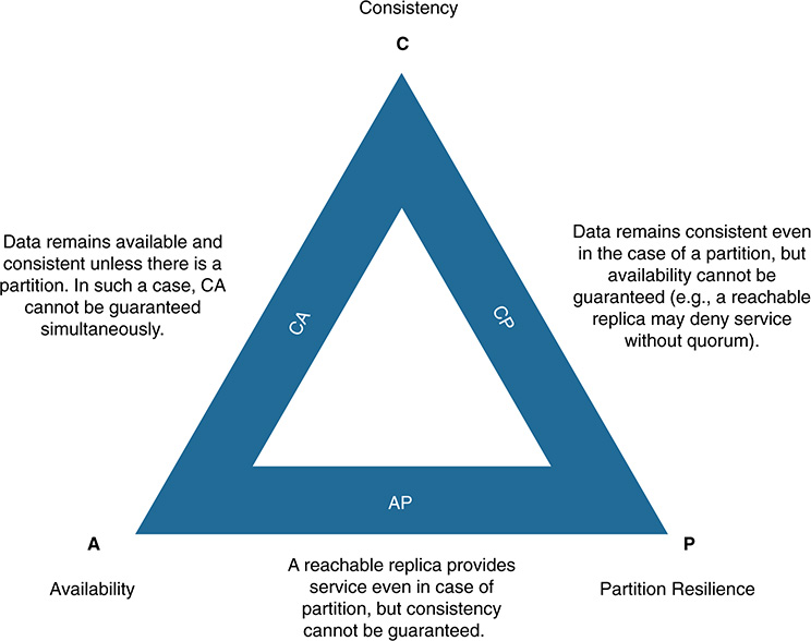
One trend that is becoming increasingly important in IIoT is the concept of a digital twin. Whereas virtual replicas and device shadows usually seek to replicate the data associated with a single device, a digital twin creates a digital copy of an entire system (see Figure 11-37). The objective is to have an up-to-date and accurate replica of the state and properties of a system. In this case, consistency is usually chosen over availability. Data is fed in real time and a large number of variables and states need to be updated continuously. The data is used to build a model of the system that can be used for simulation purposes, to streamline processes and operations, as what-if scenarios, and more. The outcomes are useful only when data consistency can be guaranteed.

Figure 11-37 Digital Twins and the Challenges They Impose on Data Protection (Source: https://www.altoros.com/blog/optimizing-the-industrial-internet-of-things-with-digital-twins)
When you are proactively planning for data protection, the implications stated by the CAP theorem are certainly relevant. Note that the use of virtual replicas immediately increases the attack surface because now the threats apply to both the real device/system and its replica. For instance, in some cases, it might be easier for an attacker to compromise the replica; even though the real device/system has not been breached, the compromised entities on the replica can be used to alter simulation results, the outcomes of what-if scenarios, and assessments and optimizations that will affect later on the real device/system. Note that the data replicated remains consistent and, therefore, secure because the source data has not been compromised. The risk in this example is breaches on entities that use the data on the replica. All these aspects are important considerations while planning for data protection.
Online and offline data backups also are mandatory to ensure data availability. Careful planning is needed around the back-end setup and the data it manages, including measures for disaster recovery. The cost of data protection versus the value of the data that is being protected is one of the most important considerations during the planning phase. Function packs that can be executed by an orchestration system can be used to this end. For instance, an industrial plant might have the back end on-premises, including the orchestration system (for example, at Level 3 for site operations and control—refer to Figure 11-1), along with a backup of relevant data at Level 5 in a corporate data center. Other IoT verticals might prefer to manage backups using a public cloud. The Function Packs that orchestrate the backups can be tailored accordingly.
In addition to proactive measures to protect the data, administrators need to plan for the actions that need to be performed when an attack is detected. Whereas proactive data protection mechanisms focus on preparing for the detection of security incidents and plan for what needs to be done, reactive mechanisms typically cover two fronts: They define how the threat is going to be contained and eliminated, and they understand what happened through data forensics and learn so that they can immediately repel the same type of attack in the future. Detecting attacks either in real time or through forensics requires collecting, processing, and analyzing data, as well as creating reports with detailed information about the incidents. The challenge is obviously how to protect the data logged.
Another key consideration when planning for data protection is regulation. For instance, in May 2018, the legal framework on data protection changed in the European Union. A new General Data Protection Regulation (GDPR) was enforced that substantially increased the regulation and protections surrounding personal data. The new GDPR introduces important fines and penalties for enterprises that do not comply with the new regulation. Although most of the protections relate to personal data, security practices for data protection do play a role in this new regulatory framework. For instance, GDPR imposes stricter obligations on data security, both on the data processing entities and on the data controllers. In particular, aspects such as potential liability in case of data security breaches will have legal consequences.
The new GDPR regulation is mostly focused on data privacy instead of data security. However, Article 32 on “security of processing” states:
1. Taking into account the state of the art, the costs of implementation and the nature, scope, context and purposes of processing as well as the risk of varying likelihood and severity for the rights and freedoms of natural persons, the controller and the processor shall implement appropriate technical and organisational measures to ensure a level of security appropriate to the risk….
In IoT, the new regulation will have ramifications that will condition how certain Function Packs are created and will be orchestrated, depending on the data they handle. It will also condition the data stored for access control and how this data is managed and replicated. Figure 11-38 illustrates the GDPR compliance ladder, starting from data governance and data protection.

Figure 11-38 GDPR Compliance Ladder (Source: Data Protection Network U.K., https://www.dpnetwork.org.uk/gdp-data-security/)
The last consideration that we cover in this chapter is the potential use of blockchain. It is becoming a game changer on data protection and management in scenarios when the parties involved do not trust each other. A blockchain is based on a distributed ledger that allows transactions (TXs) to be recorded between two parties participating in the system in an immutable and verifiable way. The transactions represent data exchanges (for example, smart contracts) and are recorded in blocks, which are added to the distributed ledger in the form of a blockchain. More specifically, a blockchain represents a continuously growing list of blocks that are linked in the form of a chain. They are secured cryptographically; each block contains a hash linked to a previous block (see Figures 11-39 and 11-40). Each participant maintains a copy of the ledger (a copy of the blockchain) and, as mentioned previously, a blockchain gathers participants in an untrusted environment. Therefore, it should offer a way to validate the transactions and the addition of a new block in the ledger. Protocol-based consensus mechanisms are used for this. In practice, two factors make a blockchain inherently resistant to change in the data recorded in the distributed ledger (refer to Chapter 17, “Evolving Concepts That Will Shape the Security Service Future,” for further details):
An attacker cannot retroactively modify a transaction in the chain without regenerating the hashes for all subsequent blocks.
Even if an attacker is capable of doing that, to make the altered copy part of the distributed ledger, the attacker needs to either break into the other participants’ networks and modify all their copies of the ledger (basically, at the same time) or conspire with a majority of the other participants to reach a new consensus (depending on the implementation, this might not even be feasible).


Figure 11-40 Transactions Are Hashed Together to Create a Block That Is Cryptographically Linked to the Preceding Block in the Chain
These two factors make blockchain records immutable in practice. The transactions are verifiable and traceable, which offers a wide spectrum of potential applications that require data protection (for example, GDPR). This should be considered especially in IoT scenarios that involve multiple parties or domains that do not trust each other.
Summary
This chapter covered the main aspects of data protection in IoT. We started by understanding the lifecycle of data and its management, and then we focused on protecting data at rest, on the move, and in use. This chapter is fundamentally centered on the confidentiality, integrity, and availability (CIA) triad, and the analysis made was complemented by specific examples involving orchestration and automation to protect data exchanges across data centers, networks, and fog. The chapter outlined other relevant aspects as well, such as the General Data Protection Regulation (GDPR) enforced in Europe in May 2018, and the immense potential of novel technologies such as Blockchain as a game changer in the space (to ensure data integrity, availability, and traceability).
References
EE Times, “Digital Data Storage is Undergoing Mind-Boggling Growth,” https://www.eetimes.com/author.asp?section_id=36&doc_id=1330462
Obermaier, D. presentation, “Securing MQTT,” BuildingIoT 2016 conference. https://www.slideshare.net/dobermai/securing-mqtt-buildingiot-2016-slides.
Serra, James, “Big Data Architectures and the Data Lake.” 2016. https://www.slideshare.net/jamserra/big-data-architectures-and-the-data-lake.
Johansson, Lovisa and J. Rhodin, Getting Started with RabbitMQ and CloudAMQP. 84 Codes AB, 2017.