Chapter 9. Identity, Authentication, Authorization, and Accounting
Topics covered in this chapter include
■ Introduction to Identity and Access Management for the IoT
■ Dynamic Authorization Privileges
■ Manufacturer Usage Description (MUD)
■ AWS Policy-based Authorization with IAM
■ Scaling IoT Identity and Access Management with Federation Approaches
■ Evolving Concepts: Need for Identity Relationship Management (IRM)
In Chapter 8, “The Advanced IoT Platform and MANO,” we discussed the building blocks and functionality required to bring automation and orchestration capabilities to a platform-type approach. Now we look at the identity and access management techniques that are evolving to assist with the explosion of new use cases and devices requiring connectivity.
The focus of this chapter is to explore the technology available for gaining identity when an endpoint attempts to access the network, methods to authenticate the endpoint, and, ultimately, automated solutions that can leverage that information to provide dynamic access privileges based on identity. We also explore how protocols such as OAuth 2.0 and OpenID Connect are helping to scale identity and authorization within IoT environments. Finally, we look at the evolution from IAM techniques to Identity Relationship Management (IRM) and its potential future applicability.
Before rolling through the agenda, it is important to have an elementary understanding of how the original or immutable identity is established. This identity will be leveraged for the access control technology concepts the chapter explores. We quickly step through some fundamental concepts on the provisioning process, various methods in which devices can be securely bootstrapped, device naming conventions, and the process of registering the devices for use. That information will establish a baseline understanding so that we can then proceed with the focus area.
We address these subjects in the following major areas:
■ Pre-network access (provisioning primer)
■ Establishing a unique naming convention
■ Establishing a trusted identity via bootstrap
■ Following an example registration and enrollment process for endpoints
■ Network access
■ Methods to gain device identity
■ Authentication methods: certificates and PKI, passwords, biometrics, AAA, 802.1X, RADIUS, and MAC Address Bypass (MAB)
■ Dynamic authorization solutions based on identity: Cisco Identity Services Engine (ISE), manufacturer usage description (MUD), and AWS policy-based authorization
■ Accounting
■ Scaling of IoT IAM with federation approaches
■ OAuth 2.0 and OpenID Connect 1.0
■ Evolution from IAM to IRM
Note In this chapter, the terms device and endpoint are used interchangeably, based on context.
Introduction to Identity and Access Management for the IoT
Every day, the Internet of Things (IoT) shifts further from concept stages into actual implementation and deployment stages. We have adopted connected lighting techniques that improve power efficiency, wearable fitness trackers that improve visibility into personal health, and even connected refrigerators that improve efficiency in shopping. Even the concept of autonomous cars promises to make one’s commute more secure while requiring less effort. The previous examples listed are only a small sample of the possibilities on the brink with IoT use cases.
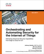
Despite how useful the listed use cases have become, we must address obstacles before we can take advantage of this technology in a secure way. One of those obstacles is scalability with identity management. The current model of using a traditional identity and access management (IAM) solution might not be applicable to IoT IAM. IoT introduces the need to manage exponentially more identities than existing IAM systems are capable of supporting. IoT identity management solutions require us not only to manage identity and authenticate human users, but also to manage billions of device identities and permissions on those users’ behalves. According to the Cisco Visual Networking Index (VNI), by 2020, approximately 25 billion devices will be connected to the Internet. Just five years later, the estimation is 74–100 billion devices by 2025. An exponential growth rate is on the horizon. Figure 9-1 illustrates the predicted device connection rate. (Note that this figure is not to scale.)
Many of these devices will need to communicate with each other and also with back-end systems. The user-to-device, device-to-cloud, user-to-cloud, and cloud-to-cloud connections that need to occur, along with the capability to grant permission on behalf of a party, is forcing a reevaluation of methodology. Our world is becoming a matrix of complex relationships.
Several solutions have been created in the last couple years to provide dynamic authorization privileges based on identity, and to do so in an automated way. This assists with scalability. Additionally, methods to extend identity and authorization capabilities by using tokens have come to fruition. These solutions are certainly useful, but they might not be enough to combat an imminent identity crisis brought on by the projected exponential IoT device connection rate.
This chapter explores the concept of Identity Relationship Management (IRM), which shows promise in dealing with the massive scalability challenges ahead. The evolution from traditional IAM to IRM will soon be at our doorstep. Because IRM concepts are still maturing, we still must leverage current identity, authentication, and dynamic authorization methods. For this reason, this chapter explores options for each category.
Device Provisioning and Access Control Building Blocks
Before we explore the methods for identifying, authenticating, and authorizing devices, we must begin by laying out a framework of building blocks to better organize these tasks.
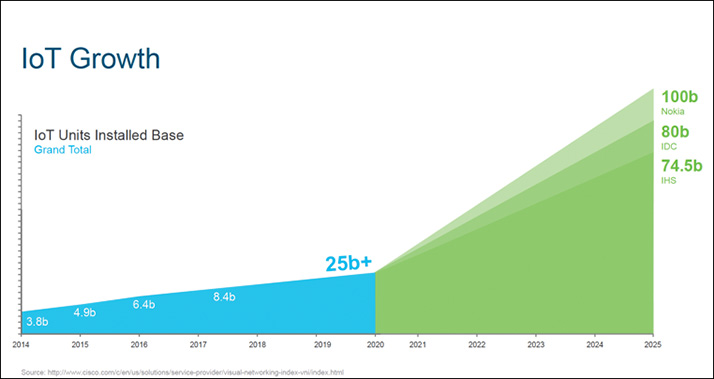
As we stated in the introduction, the focus of this chapter is to explore the access control technology required for a secure connection to the network. Specifically, this includes methods to identify the endpoint as it attempts to connect to the network, methods to authenticate its identity to ensure that the device is what it claims to be, and methods to grant the appropriate levels of authorization privileges based on the device’s identity, all in an automated way. Figure 9-3, later in the chapter, shows these categories.
Ideally, having a fundamental understanding of how a device obtains its unique identity is best before diving into access control topics. See the categories in Figure 9-2. This begins with the provisioning process and, within this context, the creation of hierarchical groupings for a device naming convention. This process then moves through creating a trusted identity for the device and, finally, enrolling the device to be used on the network. The provisioning process prepares the device to be used on the network, where the categories in Figure 9-3 can be invoked. The provisioning topic is not the focus area of this chapter, but it is important to address the beginning stages of establishing a trusted identity, which leads to more comprehensive understanding of the full lifecycle.
Figures 9-2 and 9-3 illustrate the two building block categories we explore in the next section.

This framework can be worked into a process or procedure and can be applied to all IoT devices that are procured, provisioned, registered, and ultimately used on an organization’s network.
As stated previously, for the context of this book, the provisioning process spans the naming convention, the secure bootstrap process, and device enrollment and provisioning so that it can be used securely on the network.
Naming Conventions to Establish “Uniqueness”
A common method leveraged at the beginning of the naming convention process is to create parent grouping or categories of endpoints that can be used within an organization. Creating a hierarchy of name space, similar to the Domain Name Service (DNS) or the Active Directory (AD) parent grouping structure, helps manage the volume of device types that will eventually be attached to the network. We illustrated a similar concept in Chapter 2, “Planning for IoT Security,” in the section “Segmentation, Risk, and How to Use Both in Planning the Consumer/Provider Communications Matrix.” These “unique” device names can be grouped under their parent category for optimized policy automation. Figure 2-9 in Chapter 2 shows a sample consumer/provider matrix to represent the interaction of proper groupings.
Proper groupings are an automation tool’s best friend. They allow for accuracy and repeatability, which essentially equates to improving the OPEX. Later in this chapter, we illustrate how to leverage technology to bring the matrix shown in Figure 2-9 to life.
The naming convention is an essential part of the structure and daily operation of an organization. Device naming conventions vary among companies, ranging from Extended Unique Identifiers EUI-48 and EUI-64 for MAC addresses, to IP and uniform resource indicators (URI), to Electronic Product Code for Radio Frequency Identification (RFID).
Because we are discussing a naming convention for an organization, not for the Internet, we simply must ensure that we achieve “uniqueness” for a device name; no other device can have an exact match. This can be accomplished with either determined output or randomized output. These conventions are all legitimate, and often combinations are leveraged, such as for manufacturer, application, location, and use variables.
The naming taxonomy complexity also varies between home use and company use. For home IoT use, naming conventions can be a bit more simplistic because they do not need to consider volume and geographical choices. For example, a common naming taxonomy leveraged with device counts under 50 could be location_device. For endpoint counts over 50, adding another variable would further increase scalability, as in floor3_masterbath_light1. As more devices are created with Internet connection capabilities, planning for a scalable naming scheme from the start is the best bet. An additional variable to consider for homes is the fact that many of the devices can be front-ended by natural language speech-recognition software, which allows for voice commands; thus, the names need to be distinguishable.
For company use, naming conventions might require a bit more planning, depending on the size of the company and the number of devices under management. As an example, an OUI is a 24-bit number assigned by the IEEE that uniquely identifies a vendor or manufacturer. The OUI consists of the first three octets of a MAC address. For example, an OUI for Apple is 00:CD:FE. A company may have more than one OUI, which allows it to group or categorize its parent product sets. This brings context to the naming process so that a pattern can identify a product. A MAC address, or part of a MAC address, can be used in the naming taxonomy along with the device serial number.
Regardless of the naming methodology chosen, the goal is to be able to provision the device using the unique identifier. The provisioning system thus must be able to discern one device from another.
Secure Bootstrap
IoT security has been a major topic in the industry for quite some time, particularly with the rise of smart cars, refrigerators, thermostats, and more. The growing concern of device security rests heavily on the minds of manufacturers, providers, and resellers.
A primary task within the identity framework is to establish the initial trust in the device. Ideally, if the device can be verified as a trusted unit, it has an improved chance of automated provisioning. Insecure or improper bootstrapping can be a major vulnerability because bogus data then is allowed to flow upstream and be leveraged as a DDoS mechanism; in the worst case, imposters can steal sensitive data, such as proprietary firmware. Additionally, if a device has been maliciously modified, it can be used to steal information and manipulate upstream processes.
In the context of this chapter, bootstrapping represents the provisioning of a trusted identity for a device. The bootstrapping process can begin in the manufacturing process or start when it is activated for the first time or when it is in an owner’s possession. The most secure bootstrapping methods typically are initiated during the manufacturing processes and implement discrete security associations throughout the supply chain. They use methods to uniquely identify a device in these ways:
■ Unique and unalterable identifiers stored and fused in device read-only memory (ROM)
■ Unique serial number(s) that are imprinted on the device
For example, Cisco Systems has a process that creates an immutable identity via a Secure Unique Device Identification (SUDI), as described in the following section.
Immutable Identity
The Secure Unique Device Identification (SUDI) is an X.509v3 certificate that maintains the product identifier and serial number. The identity is implemented when it is manufactured and is chained to a publicly identifiable root certificate authority (CA). SUDI can be used as an identity for configuration, security, auditing, and management; it is an identity that does not change. The SUDI credential in the Trust Anchor can be based on either RSA or Elliptic Curve Digital Signature Algorithm (ECDSA).
According to the Cisco Trust Anchor Technologies Data Sheet, the SUDI certificate, the associated key pair, and its entire certificate chain are stored in the tamper-resistant Trust Anchor chip. Additionally, the key pair is cryptographically bound to a specific Trust Anchor chip and the private key is not exported. This feature makes cloning or spoofing the identity information virtually impossible.
SUDI can be used for asymmetric key operations such as signing, verifying, encrypting, or decrypting. This capability makes remote verification of a device’s authentication possible. It enables accurate, consistent, and electronic identification of Cisco products for asset management.
Because of the lack of standards in this realm, many companies are combining their efforts and attempting to create standardization processes. Cisco has an initiative called IoT Ready that aggregates efforts among vendors, chip manufacturers, and the user community, to support standardization and certification. The standardization provides a set of guidelines that support a more comprehensive device identity process that can then be leveraged in the network access policies. Part of the IoT Ready initiative is working with device vendors to standardize the use of onboarding and access control mechanisms within devices. Personalizing the endpoint with a specific identification number and coupling that with a robust unique cryptographic identity such as PKI has significantly improved the bootstrap process.
After the unique identifiers are either imprinted on the device or stored in ROM, they are to be shipped securely from the manufacturer to a trusted facility in a tamper-resistant enclosure. These facilities must have the proper physical security measures in place, along with a thorough logging process.
The secure bootstrapping process can vary in comprehensiveness and should be tailored based on the industry in which the device will be used, the specific functions it will be performing, and the criticality of the data to be managed. Consumer-grade IoT devices might not have the stringent controls that a regulated industry requires, but the more connectivity we have, the greater the risk becomes to affect a broader spectrum. In a regulated space such as the payment card industry (PCI), the risk is high; thus, attaching more comprehensive bootstrapping procedures is critical. The most secure processes generally implement multiparty integrity procedures and documented separation of duties in the device bootstrap process.
This chapter explores the use of certificates (both X.509 and IEEE 1609.2) and PKI. For more detail, see the later sections “Certificates” and “Private Key Infrastructure.”
Bootstrapping Remote Secure Key Infrastructures
Bootstrapping can also be an automated process, using solutions such as the Bootstrapping Remote Secure Key Infrastructure (BRSKI). This automated process leverages vendor-installed X.509 certificates, in combination with a vendor-authorized service on the Internet. BRSKI works with Enrollment over Secure Transport (EST; RFC 7030) to enable zero-touch joining of a device in a network domain.
This process can be invoked using link-local connectivity or a routable address and a cloud service. Support for constrained devices (those that have constraints in the form of power draw, CPU, memory, and so on) is described for legacy reasons but is not encouraged. According to the IETF draft “Bootstrapping Remote Secure Key Infrastructures,” BRSKI provides a foundation to answer the following questions in a secure manner between a network domain element called a Registrar and an unconfigured, untouched device called a Pledge:
■ Registrar authenticating the Pledge: Who is this device? What is its identity?
■ Registrar authorizing the Pledge: Is it mine? Do I want it? What are the chances that its been compromised?
■ Pledge authenticating Registrar/Domain: What is this domain’s identity?
■ Pledge authorizing the Registrar: Should I join it?
The BRSKI process is considered complete when the cryptographic identity of the new key infrastructure is successfully deployed to the device. This approach provides a secure zero-touch method for enrolling new devices without any prestaged configuration. This process is referenced later in this chapter in the section “Manufacturer Usage Description.”
This Internet draft is in full accordance with BCP 78 and BCP 79. The BRSKI provisioning process is described in full detail in the BRSKI Internet Draft, at https://tools.ietf.org/html/draft-ietf-anima-bootstrapping-keyinfra-07#section-3.8.
Device Registration and Profile Provisioning
When the company receives the device, that device must be enrolled or registered for use on the network. The overall goal of the registration and profile provisioning process is to give an endpoint the logic it requires to make a secure connection to the network and operate within the company policy guidelines. The following steps are common:
■ Create and associate the naming convention or taxonomy with the device.
■ Prepare the device to participate in PKI (if not done already) by installing trust anchors and certificates for the certificate authority (CA) being leveraged and any intermediate registration authorities (RA).
■ Provision the private keys and device certificate signed by the CA so that the device can participate as a trusted unit on the network.
■ Download the profile (such as SSID info and encryption to be used), giving the device the capability to connect to the network.
■ Configure the device with day 0 information, such as its IP address, its local server address, and a default gateway.
Many vendors use different forms of this registration or enrollment process, each with varying steps and capabilities. Provisioning device certificates manually for each device would be a painstaking process; depending on the device type, certain methods can automate the process. We walk through two instances using provisioning examples from AWS and Cisco Systems.
Provisioning Example Using AWS IoT
Let’s walk through an elementary example of the Amazon Web Services (AWS) IoT device registration process.
Devices connected to the AWS IoT platform are represented by things in what they refer to as their “thing registry.” The thing registry maintains a record of all the devices that are connected to the AWS IoT account. The process begins by creating a device entry, which must be named. This is an example of how the unique naming convention can be applied.
Figure 9-4 illustrates adding the temperature sensor to the registry, beginning with creating the naming taxonomy process described previously.

The next step is to associate attributes to the thing that can be used in search criteria or, for a more comprehensive identity, by coupling variables. Figure 9-5 illustrates attaching attributes to the temperature sensor.

We now need to download and install the connection kit. If you choose the option for AWS to create the certificate and key pairs, it will be available to download as part of the connection kit. Figure 9-6 illustrates using the AWS-created certificate along with the public and private key pairs, which are made available for download and installation.

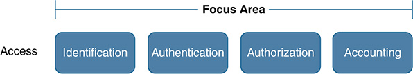
Figure 9-7 shows the downloaded package, which contains the certificate and associated key pair.
Several methods exist for managing certificates, and different IoT platform vendors might select different choices. You may choose to have the IoT platform vendor do the provisioning, to create both the certificate and the public/private key pairs. Another method might allow customers to bring their own certificates (BYOC); the customers then are responsible for creating the certificate for every device. A third option entails having customers generate their public/private keys and certificate signing request (CSR) and then sending the CSR to the IoT vendor’s CA to be signed.
AWS offers all three options for certificate management. See Figure 9-8 for certificate management options, along with the pros and cons for each.

Once the accounts and associated credentials have been provisioned, a process or procedure must be instituted to monitor the accounts against a defined set of criteria, to ensure policy adherence. Examples include the following:
■ Account monitoring and control: Toolsets that audit device administrative credentials should be deployed. This includes using strong password policies and rotating crypto keys.
■ Account discontinuance: A policy should address disabling credentials due to suspension status and/or deleting credentials due to an employment status change. Credentials, crypto keys, and certificates all need to be considered here. Having the keys in the wrong hands can lead to reverse-engineering attempts and unwanted compromise.
Provisioning Example Using Cisco Systems Identity Services Engine
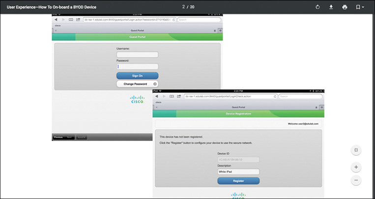
Cisco Systems also has an onboarding solution to self-register an endpoint for both wired and wireless users. This approach allows employees to manage onboarding their own devices through a self-registration workflow, simplifying the automatic provisioning of supplicants and certificate enrollment for the most common BYOD devices. The workflow supports iOS, Android, Windows, and Mac OS devices. It assists in transitioning these devices from an open environment to a secure network with the proper access, based on device and user credentials. This is particularly helpful for industrial environments that want to institute the use of BYOD in plants.
Workflows exist for both guest users and employees who want to use their own devices in a secure manner. Let’s walk through an example that allows an employee to bring in and provision a mobile device to be used on the company network, while at the same time allowing IT to enforce the appropriate access policies based on company policy.
Note ISE does not have an automated provisioning workflow for “things” to gain identity credentials. The workflow downloads a supplicant to the endpoint that walks the user through the provisioning process.
This entails downloading a supplicant that assists with the registration process, downloading a device certificate, and downloading the corporate wireless information (SSID and encryption method) to enable a connection to the secure company network. Consider the following process:
The employee connects to the provisioning SSID and is redirected to the Guest Registration portal for registration after opening a browser.
The employee enters the Active Directory credentials. If the device has not yet registered, the session is redirected to the self-registration portal, where the user is asked to enter a description for the new device.
The employee is not allowed to change the Device ID (MAC address); it is automatically discovered by the Cisco Identity Services Engine (ISE). (The next section introduces ISE.) Figure 9-9 illustrates the self-registration portal.
The supplicant profile is downloaded and installed on the endpoint.
Keys are generated and the certificate is enrolled.
The Wi-Fi profile required to connect to the BYOD_Employee is installed.
Figure 9-10 shows the supplicant profile being downloaded, along with the certificate enrollment, key generation, and download and installation of the Wi-Fi profile (which provides the SSID and encryption information required to establish a secure connection to the company SSID). After the download and installation of these profiles, the employee is notified that registration is complete and is reminded to manually connect to the BYOD_Employee SSID.

In summary, the AWS and Cisco registration and enrollment processes differ in terms of procedure and options available, but both give users the option of onboarding their own devices through a self-registration workflow. This simplifies the automatic provisioning of device enrollment and also assists with certificate deployment, which can be useful in terms of endpoint provisioning scalability.
The preceding section provided an elementary discussion of some of the prerequisites that must be met before an endpoint is allowed to gain access to network resources. These include bootstrapping an endpoint with a trusted identity, providing for a unique naming taxonomy, associating attributes with the endpoint for distinguishability, and ultimately enrolling the endpoint to be used on the network. The intent is to leverage that information to dynamically extrapolate those unique “fingerprints,” to identify the endpoint through the profiling process as it seeks access to the network, authenticate it, and grant the appropriate access privileges based on its identity. The next section explores those options in detail.
Access Control
As the cliché goes, we can’t properly secure what we can’t see. The identification process is a critical step in the access control process and works as a prerequisite to the automation logic that ensues. When a device is properly identified, it must be evaluated to determine whether it belongs on the network. After successful authentication, appropriate access privileges (authorization) can be granted, based on the device’s identity. These authentication and authorization steps require a properly documented trail that feeds into the accounting process. The accounting process also measures and keeps track of the resources a user consumes while accessing the network. The steps in this framework (identification, authentication, authorization, and accounting), shown in Figure 9-11, work in concert, as we explore in the following section.

Identifying Devices
So how is a device identified? Several methods can identify a device; this process varies significantly, depending on the device type and the connection method. Let’s walk through how these variables affect identification capabilities.
Cisco Systems has a product called the Identity Services Engine that combines endpoint identity, authentication, and authorization into a comprehensive access control solution. ISE essentially translates business policy into technical rules that are enforced electronically throughout a network. It was created to give organizations an integrated architecture approach for both network access and policy constructs. The concept is quite logical: to control policy from a single console. This encompasses the following:
■ Secure access via medium (wired, wireless, remote access)
■ Secure access via location (branch, campus, headquarters, remote user)
■ Secure access via endpoint (printer, computer, camera, medical device)
■ Secure access for any person (employee, contractor, vendor, guest)
For Cisco, ISE is its authentication, authorization, and accounting (AAA) server on steroids. It also adds in the important capabilities of embedded profiling, posture, guest services, and PKI capability. The solution addresses the important questions of who, what, when, where, and how for various media options (wired, wireless, and remote access). ISE also connects to back-end authentication and authorization databases to enhance the “one-stop shop” theory of AAA, such as authenticating via Active Directory, LDAP, SQL, CAs, and external identity providers (iDP). Figure 9-12 illustrates ISE’s integrated approach to AAA.
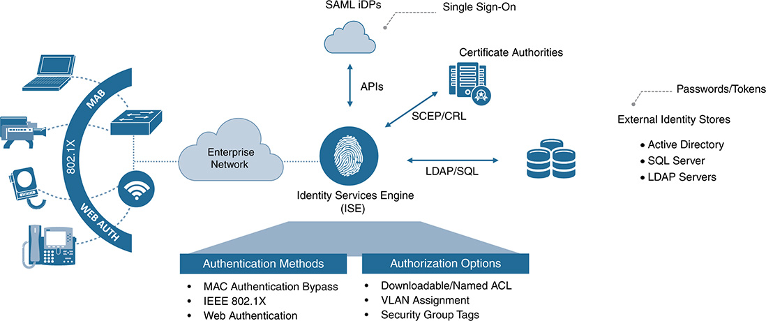
Again, ISE is an integrated architecture that aggregates identity with AAA. Next, we explore the beginning stages, with methods to gather identity.
Endpoint Profiling
Profiling data can be gathered from endpoints in different ways, as the following sections explore.
Profiling Using ISE
The ISE profiling process is an automated process of device discovery and classification. It is a key service responsible for identifying, locating, and determining the capabilities of endpoints that attach to the network, to deny or enforce specific authorization rules. The following are two of the main profiling capabilities:
■ Collector: Collects network packets from network devices and forwards attribute values to the analyzer.
■ Analyzer: Determines the device type by using configured policies that match attributes.
Two main methods collect endpoint information:
■ ISE acts as the collector and analyzer.
■ The infrastructure acts as the collector and sends the required attributes to ISE, which executes the analyzer portion.
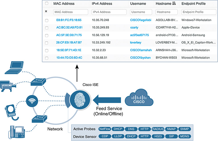
We discuss ISE as the collector and analyzer first. This approach is based on the use of collectors, referred to as probes. Probes use specific methods and protocols to collect attributes about each endpoint. The specific information a probe collects depends on the protocol and method implemented. Cisco ISE supports various probes, which we describe later in the chapter; each probe is capable of capturing different data points. Raw data for a given endpoint is parsed and stored in the ISE internal endpoint database. Relevant endpoint attributes are then analyzed against a library of fingerprinting rules known as profiler policies. Different attributes and rules have different weighting factors in the final endpoint classification, depending on the reliability of the data. Profiling is never an exact science; it is merely the process of collecting and aggregating variables to improve levels of certainty. Figure 9-13 provides an elementary view of the ISE profiling capability leveraging probes.
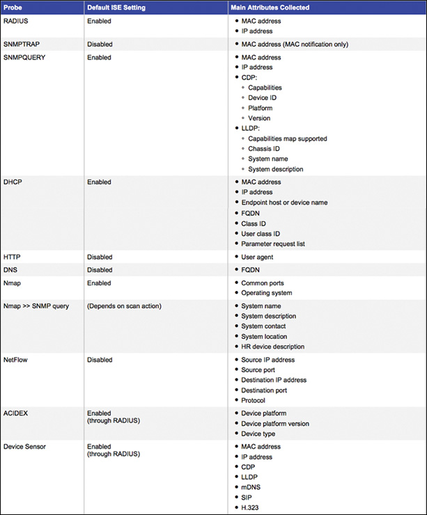
Each probe contributes different information about the endpoint. The goal is to deploy probes that optimize the collection process while adding unique value in the form of Type-Length-Value (TLV) to the classification. Additionally, the network must be designed and configured to support the collection. Figure 9-14 shows the list of embedded probes with ISE, along with the main attributes they gather.
ISE comes with definitions for thousands of endpoint detections and classifications on day one. These definitions can be updated via online or offline feed services for greater fidelity and up-to-date information. The information (or unique TLVs) about the endpoints can be gathered either using active probes or with the assistance of the device sensor feature on the network devices.
Profiling is not an exact science. Profiling is simply the process of gleaning protocols, extrapolating unique TLVs to leverage as fingerprints, and coupling as many TLVs as possible to increase the level of certainty. The more variables you can couple together, the better your chance for accuracy. Figure 9-15 illustrates the profiling policy in ISE for an Apple MacBook.
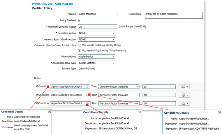
Figure 9-15 shows three conditions. With each condition that is successfully met, the certainty level increases. For our purposes, it would be enough to obtain just one of the three conditions shown because the minimum certainty factor to successfully profile an Apple MacBook is 20.
This policy is called a canned policy in ISE. Cisco has developed about 500 canned profiles that use the various probes. The profiling library is preconfigured in ISE and is continually updated using the automated Feed Service. ISE provides the capability to modify any of the canned profiles, and administrators can create customized profiles as well.
In addition to the default profiles, Cisco has created a library of specialized profiles, per industry. For example, the medical field commonly uses the Identity Services Engine. A fair number of specialized devices, such as electronic sensors, bio devices, controllers, and imaging systems, require unique privileges. Cisco has created medical device profiles that healthcare delivery organizations can download from Cisco.com. The Cisco Medical NAC Profile Library will continue to evolve: As of February 2016, it contained more than 250 medical device profiles.
Device Sensor
Cisco introduced a capability called Device Sensor in its access infrastructure (LAN switches and wireless LAN controllers) to bolster ISE’s endpoint profiling process. The sensor gleans information from specific protocols, such as MAC address, IP address, CDP and LLDP details, DHCP option fields, and HTTP user agents, and sends that raw data to ISE via RADIUS. Device Sensor makes that information available to its registered clients in the context of an access session. The access session represents an endpoint’s connection to the network. This is particularly useful for access control because we can leverage the TLVs acquired to learn the who, what, when, where, and how; we then can use that information to make a real-time decision on granting an endpoint access and authorization. We explore the access control piece later in this chapter.
The profiling capability of Device Sensor consists of two portions:
■ Collector: Gathers endpoint data from network devices
■ Analyzer: Processes the data for device determination
The Device Sensor represents the embedded collector functionality. Figure 9-16 shows where Device Sensor resides in the context of the profiling system.
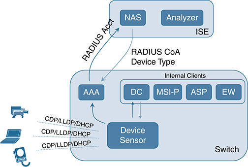
Device Sensor has both internal and external clients. Internal clients include the embedded Device Classifier (local analyzer), ASP, MSI-Proxy, and EnergyWise (EW). The Identity Services Engine (ISE) is the external client and analyzer shown; it leverages RADIUS accounting to receive additional endpoint data.
The client notifications and accounting messages (which can contain profiling data, MAC addresses, and ingress port identifiers) are generated and sent to both internal and external clients.
Device Sensor has built-in port security that protects the switch from consuming memory and crashing, thus limiting intentional DDoS-type attacks.
Let’s look at an example of configuring the Device Sensor feature so that it can be used for profiling purposes on ISE. Device Sensor will collect information about connected endpoints by gleaning the following protocols and extrapolating the requisite TLVs for which it is configured:
■ Cisco Discovery Protocol (CDP)
■ Link Layer Discovery Protocol (LLDP)
■ Dynamic Host Configuration Protocol (DHCP)
The process begins with enabling the AAA, 802.1X, and RADIUS, and then enabling the appropriate protocols. See the standard AAA configuration example in Example 9-1.
Example 9-1 Standard AAA Configuration Example
aaa new-model
!
aaa authentication dot1x default group RADIUS1
aaa authorization network default group RADIUS1
aaa accounting update newinfo
aaa accounting dot1x default start-stop group RADIUS1
!
aaa group server radius RADIUS1
 server name ISE1
radius server ISE1
 address ipv4 10.1.X.X auth-port 1645 acct-port 1646
 key cisco

!
dot1x system-auth-control
!
lldp run
cdp run
!
interface GigabitEthernet1/0/13
 description IP_Phone_8941_connected
 switchport mode access
 switchport voice vlan 101
 authentication event fail action next-method
 authentication host-mode multi-domain
 authentication order dot1x mab
 authentication priority dot1x mab
 authentication port-control auto
 mab
 dot1x pae authenticator
 dot1x timeout tx-period 2
 spanning-tree portfast
end
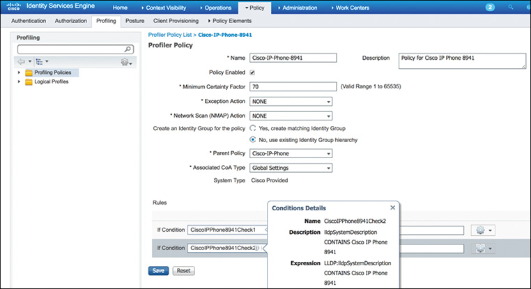
The attributes required to profile the device must then be determined. We moused over one of the checks (check 2) so that you can see how it references the lldpSystemDescription variable. Check 1 was for cdpCachePlatform (not shown) via the mouseover. Figure 9-17 illustrates the lldpSystemDescription variable.
The Device Sensor–specific portion of the configuration now begins:
■ Configure two filter lists, one for CDP and another for LLDP. These indicate which attributes should be included in RADIUS accounting messages. This step is optional; all are included by default.
■ Create two filter specs for CDP and LLDP. One filter spec indicates that list of attributes should be included or excluded from accounting messages. In the example, the following attributes are included:
■ device-name from CDP
■ system-description from LLDP
■ If needed, additional attributes can be configured and transmitted to ISE through RADIUS. This step is also optional.
■ Add the command device-sensor notify all-changes. It triggers updates whenever TLVs are added, modified, or removed for the current session.
■ To transit the information gathered via Device Sensor functionality to ISE, the switch must be configured to do so with the command device-sensor accounting.
Example 9-2 illustrates the Device Sensor probe configuration.
Example 9-2 Device Sensor Probe Configuration
device-sensor filter-list cdp list cdp-list
 tlv name device-name
 tlv name platform-type
!
device-sensor filter-list lldp list lldp-list
 tlv name system-description
!
device-sensor filter-spec lldp include list lldp-list
device-sensor filter-spec cdp include list cdp-list
!
device-sensor accounting
device-sensor notify all-changes
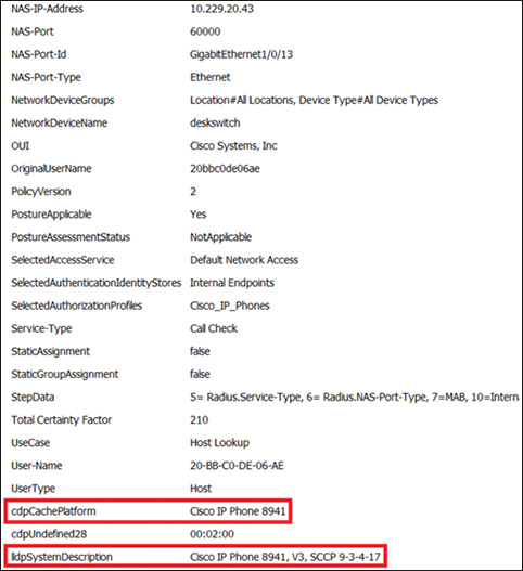
After configuring the authentication and authorization policies, the Cisco IP Phone can be successfully profiled. Figure 9-18 illustrates how ISE leveraged both the cdpCachePlatform and lldpSystemDescription variables to successfully profile the endpoint.
The important point is that differentiated authorization privileges should be provided, based on the information received. For example, you might need to differentiate between contractor devices and employee devices, between employees bringing in their own mobile devices and company-issued assets, between whether a user is on or off the network, or even between times of day. Contractors might be authorized to be onsite only Monday through Friday from 8:00 a.m. to 5:00 p.m.; vendors who need to enter on weekends might require differentiated access. The more information you can acquire, the more granular the policy can become. We explore the authentication and authorization sections later in this chapter.
Methods to Gain Identity from Constrained Devices
Devices fall into two major categories, constrained and complex. The term constrained devices was introduced to describe devices that have more stringent resource capabilities when compared to the common desktop computer (complex). This chapter does not exhaustively explore the constrained category, but it provides a baseline discussion of the category and its associated limitations so that you can employ the proper security considerations.
Before we discuss how to use standard IoT protocols to gain identity from constrained devices, we need to quickly walk through the classes of constrained devices.
Restrictions on constrained devices potentially include the following:
■ Less computational power (MegaFLOPS versus TeraFLOPS)
■ Reduced power consumption (mWatt versus Watt)
■ Less memory and/or flash, along with less buffer space (kilobytes versus gigabytes)
■ Potentially based on microcontrollers that provide a limited set of functionality and constraints on the user interface, such as the capability to set keys and update software
These types of constraints can make the device identification process challenging. Varying degrees of constraint are bolstering efforts to create categories.
Terminology was created for different classes of constrained devices in RFC 7228, “Terminology for Constrained-Node Networks.” Classes are defined for RAM/flash, energy limitation, and strategy for using power for communication.
Table 9-1 lists the RAM/flash classes of constrained devices.
Table 9-1 Classes of Constrained Devices (KIB = 1024 Bytes)
Name |
Data Size (RAM) |
Code (Flash) |
|---|---|---|
Class 0, C0 |
10 KB |
100 KB |
Class 1, C1 |
–10 KB |
–100 KB |
Class 2, C2 |
–50 KB |
–250 KB |
Class 0:
Severely constrained in memory and processing capabilities, and most likely cannot communicate directly with the Internet in a secure manner
Communicate via proxy or gateway devices
Cannot be managed or secured in a comprehensive manner
Most likely are preconfigured and might not have the capability to be reconfigured
Can respond to keepalives and send basic health status
Class 1:
Constrained in processing capabilities and flash/code space, and are unable to communicate with other devices that leverage the full protocol stack (HTTP/TLS/XML-based data representations).
Capable of using a protocol stack specifically designed for constrained nodes, such as Constrained Application Protocol (CoAP) over UDP, and can participate in conversations without the use of a gateway
Can leverage that protocol stack to provide support for security functions required on a larger network, and therefore can be integrated into an IP network
Need to be frugal with code space, memory, and power expenditure
Class 2:
Fundamentally capable of supporting most of the same protocol stacks used on desktops and powerful mobile devices
Can still benefit from lightweight and energy-efficient protocols that consume fewer resources
Energy Limitations
Certain devices are limited in available energy or power. Any device that does not have a limit is classified as E9. Energy limitation can refer to a certain time period or the device’s usable lifetime. When a device is discarded after its available energy has ceased, it is classified as E2. When the limitation refers to a period of time, such as solar energy being produced only during daylight hours, this classification is E1. Table 9-2 shows example energy limitation classifications.
Table 9-2 Classes of Energy Limitation
Name |
Type of Energy Limitation |
Example Power Source |
|---|---|---|
E0 |
Event energy limited |
Event-based harvesting |
E1 |
Period energy limited |
Battery that is periodically recharged or replaced |
E2 |
Lifetime energy limited |
Nonreplaceable primary battery |
E9 |
No direct quantitative limitations available |
Mains powered |
Strategy for Using Power for Communication
When wireless transmission is leveraged, the radio can consume a large portion of the device’s energy total. Different strategies address both power usage and network attachment, based on the energy source and the frequency the device leverages to communicate. Table 9-3 lists the general strategies.
Table 9-3 Strategy of Using Power for Communication
Name |
Strategy |
Capability to Communicate |
|---|---|---|
P0 |
Normally off |
Reattach when required |
P1 |
Low power |
Appears connected, perhaps with high latency |
P9 |
Always on |
Always connected |
■ Normally off: The device sleeps for long periods at a time. When it wakes up, it reattaches itself to the network. The goal is to minimize effort during the reattachment phase and the resulting application communication.
■ Low power: The device operates on small amounts of power but still communicates on a relatively frequent basis. This implies that extremely low-power solutions need to be used for the hardware, chosen link-layer mechanisms, and so on. Typically, with their small amount of time between transmissions, these devices retain some form of attachment to the network despite their sleep state. Techniques for minimizing power usage for network communications include minimizing any work from re-establishing communications after waking up and tuning the frequency of communications (including duty cycling, in which components are switched on and off in a regular cycle) and other parameters.
■ Always on: This strategy is applicable if extreme power-saving measures are not required. The device remains active in the usual manner. Consider leveraging power-friendly hardware or limiting the number of wireless transmissions, CPU cycles, and general power-saving tasks.
Billions of additional devices will be connected to the Internet, and a fair number of them might be using predominantly machine-to-machine (M2M) communication; they might present only external interfaces that are not primarily designed for human interaction. Couple that with the constraints listed, and constrained device identification can be challenging. Leveraging an 802.1X supplicant or PKI for identification on constrained devices might not be possible, so what about analyzing the protocol it currently uses for communication?
Leveraging Standard IoT Protocols to Identify Constrained Devices
Figure 9-19 shows a communication pattern for uploading sensor data to an application service provider. If you are considering supporting constrained devices (see the right side), the protocols on the left side might not be suitable. As an example, data encoding schemes and transport protocols that are based on human-readable encoded data are verbose and thus not efficient enough when memory and energy resources are limited. Binary-based protocols, such as Constrained Application Protocol (CoAP) and Message Queue Telemetry Transport (MQTT), better fit M2M and IoT requirements on constrained devices.
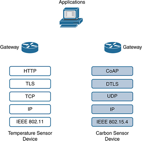
Figure 9-19 Communication Stack Difference Between a Common Web Stack and a Stack for Constrained Devices
Vendors generally want to leverage popular protocols, which leads to increased adoption, but these options might not be possible, depending on the device constraints. Less widely available radio technologies (such as IEEE 802.15.4) could be needed, or special application-layer functionality (such as local authentication and authorization) might need to be provided for interoperability. Figure 9-19 illustrates the difference in protocol stacks for a common web stack versus a constrained stack.
If we consider the right side of Figure 9-19 to be a constrained device that leverages the communication stack, are there efficient methods to gain its identity? Depending on the protocol, sometimes the protocol format itself can be leveraged to gain identity variables, or the security overlay can help extrapolate additional identity information.
CoAP
The Representational State Transfer (REST) architecture has become widely leveraged in most applications and architectures on the web. One of the main goals of CoAP is to provide a REST architecture that is better suited for constrained environments. This protocol is used often, particularly in M2M scenarios, to build automation and energy. It aims to keep the message overhead smaller and limit the need for fragmentation. Some features include the following:
■ A web protocol that fulfills M2M requirements in constrained environments
■ Asynchronous message exchanges
■ UDP binding to support unicast and multicast requests
■ URI and content-type support
■ Low header overhead and parsing complexity
■ More simplistic proxy and caching capabilities
■ A stateless HTTP mapping, allowing proxies to provide access to CoAP resources via HTTP and also allowing simple interfaces to integrate with CoAP
■ Security binding to Datagram Transport Layer Security (DTLS)
The interaction model of CoAP is similar to the client/server model of HTTP. However, M2M interactions can also cause a device to take on both client and server roles. The CoAP messages are exchanged asynchronously between CoAP endpoints, and CoAP is bound to unreliable transports such as UDP.
The endpoint depends on the security model used. With no security, the endpoint is solely identified by an IP address and a UDP port number.
A common approach to providing enhanced identification and authentication for CoAP is to use Datagram Transport Layer Security (DTLS). DTLS can be leveraged in three ways:
■ PreSharedKey: DTLS is enabled and a list of preshared keys is generated. Each key includes a list of nodes that it can be used to communicate with.
■ RawPublicKey: DTLS is enabled and the device has an asymmetric key pair without a certificate (a raw public key) that is validated using an out-of-band mechanism.
■ Certificate: DTLS is enabled and the device has an asymmetric key pair with an X.509 certificate (RFC 5280) that binds it to its subject and is signed by a trust root.
PKI, certificates, and trust anchors are described in more detail in the later section “Authentication Methods.” Again, with no security, an endpoint using CoAP communicates via IP and UDP; that IP address and the UDP port number become its identifiers.
MQTT
MQTT was invented in the late 1990s to create a protocol for constrained devices that can address challenges in both battery power and bandwidth. MQTT is a client/server publish/subscribe messaging transport protocol that is lightweight, open, and simple to implement. However, it has been widely unused in M2M and IoT environments to address bandwidth and code footprint constraints. In October 2014, the protocol was approved as an OASIS standard.
MQTT decouples the publisher and subscriber, so the client connection is always done with the broker. Figure 9-20 shows the working components of MQTT.

■ Client: An MQTT client is any device, from a micro controller up to a full-fledged server, that has an MQTT library running and is connecting to an MQTT broker over any kind of network. This can be a small device with resource constraints. The device must have a TCP/IP stack because it leverages TCP and IP, using MQTT over the top. This protocol is ideally suited for constrained IoT-type devices that can leverage the publish/subscribe model. MQTT client libraries are available for a wide variety of programming languages, including Android, Arduino, C, C++, Go, iOS, Java, JavaScript, and .NET.
■ Broker: The broker is the heart of any publish/subscribe model. Depending on the implementation, a broker handles thousands of concurrent MQTT clients. The broker receives all messages, filters them, determines who is subscribed to the topic at hand, and ultimately delivers the message to the subscribed clients. It keeps a session database of persisted clients that includes subscriptions and missed messages. The broker also handles authentication and authorization of clients. Often the broker is extensible, capable of integrating into additional back-end systems. This delivers customized authentication and authorization capabilities.
The MQTT connection is always between one client and the broker; no clients connect to each other directly. The connection is initiated when a client sends a CONNECT message to the broker. Within that CONNECT message there lies a ClientId, username, and password. Figure 9-21 illustrates these fields in the MQTT CONNECT packet.
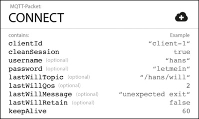
The ClientId is the identifier of each MQTT client connecting to an MQTT broker. This ClientId must be unique per broker because the broker uses it to identify the client and its associated state. If you do not require state to be maintained, you can send an empty ClientId, resulting in a connection without state.
MQTT also enables you to send a username and password for authenticating the client and for authorization. This password is transmitted in plain text if it was not encrypted or hashed by leveraging TLS. Using a secure transport username/password field is recommended; we cover this shortly in the “Authentication Methods” section.
In summary, gaining identity from constrained devices can be challenging, but you can leverage the standard protocol it uses for communication or the security protocol overlay.
Authentication Methods
In contrast to desktops and personal mobile devices, IoT endpoints can vary from a light bulb to manufacturing equipment. Additionally, these devices grow in complexity as they progress along the IoT maturity model. At one end are simple sensors, such as smart refrigerators and wearables; at the other are more complex autonomous devices that perform action without human direction or intervention, such as a smart vehicle.
The intelligence and authentication capabilities of these endpoints also vary, thus requiring the network to support various authentication methods. This section explores the use of passwords, keys, certificates, client/server methods such as 802.1X and RADIUS, and biometrics.
Certificates
IoT has several requirements when it comes to security, but trust and control top the list. These two vary greatly depending on the device type, its nature of use, and also its given constraints. Regardless of the variants, cryptography plays a role. PKI and crypto technologies have proven both worthy and valuable in large-scale systems such as the financial and medical fields. PKI has performed well for years in trusted environments where millions of device certificates have been deployed for ATMs, cellular base stations, and smartphones. Although the “things” in IoT have much in common with these devices, they raise some new issues regarding assurance, scale, and technology.
Public key cryptography is based on the concept of a unique relationship between two distinct variables used to encrypt data. One of the variables is made public (the public key), and the other is kept private (the private key). When coupled together, the relationship seems to be valid. This is also known as asymmetric encryption because one key is used to encrypt and a related key is used to decrypt.
A digital certificate is analogous to a virtual passport. A passport contains an image, name, country of residence, place of birth, validity period, and so on to accurately validate a person’s identity. Similarly, a digital certificate contains fields that validate the identity of a device as it relates to a corresponding public key. Figure 9-22 illustrates the contents of a digital certificate.

As this book has pointed out many times, constrained devices will populate the IoT, and traditional cryptography might not be suitable (not enough RAM, flash, CPU power, and so on). Some adjustments thus might be required. Be sure to consider the following forms of digital certificates.
X.509
An X.509 certificate is a digital credential that associates an identity with a public key value. According to a Red Hat document, an X.509 certificate can include the following:
■ A subject’s distinguished name (DN) that identifies the certificate owner
■ The public key associated with the subject
■ X.509 version information
■ A serial number that uniquely identifies the certificate
■ An issuer DN that identifies the CA that issued the certificate
■ The digital signature of the issuer
■ Information about the algorithm used to sign the certificate
■ Some optional X.509 v.3 extensions (for example, an extension that distinguishes between CA certificates and end-entity certificates)
IEEE 1609.2
The IEEE 1609.2 certificate is about 50 percent of the size of the X.509 format. Despite its size, this certificate can leverage elliptic curve cryptographic algorithms (ECDH and ECDSA). The certificate is primarily used for M2M. In particular, the connected vehicle initiatives explore the use of on-board equipment (OBE) that communicates with other drivers in the vicinity using basic safety messages (BSM). Considering the number of potential vehicles communicating and the fact that the Dedicated Short-Range Communications (DSRC) wireless protocol is limited to a narrow set of channels, communications clearly needed to be secured and the security overhead of BSM transmissions needed to be minimized. This ushered in the sleeker 1609.2 certificate format. This new format has unique attributes, described as an explicit application identifier (SSID) and credential holder permission (SSP) fields. They allow IoT applications to make access control decisions without having to query for the credential holder’s permissions because they are embedded in the certificate.
Billions of certificates will be issued as IoT continues to evolve. These certificates will be used to identify devices, encrypt and decrypt communications, and sign firmware and software updates. Thankfully, trusted and proven solutions are capable of enhancing the security, efficiency, and manageability of digital certificates using PKI solutions.
Private Key Infrastructure
PKI is a key-management system that provisions asymmetric (public key) key material in the form of digital credentials. One of the most common formats is X.509, discussed earlier. PKI has been used for decades and is both a trusted and reliable form of authentication; it should be considered for confidentiality whenever appropriate. Despite its name, PKIs can operate publicly, can be Internet-based services, or can operate within a private organization.
When an identity needs to be asserted, a digital certificate is issued to a device that can perform a variety of cryptographic functions, such as signing messages and performing encryption and decryption.
Depending on implementation, different workflows are used to generate the public and private key pair. Centrally generated certificates and self-generated certificates exist. In the self-generation process, the device is commanded to generate a public/private key pair along with a certificate signing request (CSR). The CSR contains the device’s public key, and is sent to the certificate authority (CA) for signing. The CA signs with its private key and returns it to the device for use. The next section discusses cryptographical signing and the CA’s role in the PKI.
PKIs provide “verifiable” roots of trust and can adhere to a plethora of architectures. Some PKIs contain shallow trust chains with only a single parent CA; others have more comprehensive trust chains with varying levels. Figure 9-23 illustrates a PKI architecture.

The following example walks through a scenario leveraging the components shown in Figure 9-23.
When an IoT device requires a trusted identity, it leverages a trusted third party to verify or prove its identity (it enters the PKI architecture). The PKI uses a CA, which is responsible for cryptographically signing endpoint certificates. Most PKI infrastructures do not allow endpoints to interact directly with the CA and instead use an intermediate node, referred to as a registration authority (RA). The components work together in the following way:
The endpoint generates the key pair and CSR.
The endpoint sends the CSR to the RA, which contains the unsigned public key.
The RA verifies that the CSR meets the defined criteria and passes the certificate request to the CA.
The CA signs the certificate using an algorithm such as RSA, ECDSA, or DSA.
The CA sends the signed certificate request, called the certificate response, back to the RA.
The endpoint receives the certificate response, which contains the CA’s signature and explicit identity.
After the device installs the signed certificate, it can present that certificate during authentication. Other devices then can trust it as well. The trust stems from the fact that the certificate was signed by the CA and can be validated using the CA’s public key trust anchor, which is commonly stored in an internal trust store (the previous example assumes that the opposite end has the CA keys). See the upcoming section “Trust Stores” for a more thorough explanation.
What if endpoints have certificates that are signed by different PKIs? That scenario is fairly common, and it is handled with either explicit trust or cross-certification.
■ Explicit trust: This is one of the most common scenarios on the Internet. Each entity supports a policy that allows one to trust the other. Endpoints simply need to have a copy of the trust anchor from the other entity’s PKI to establish the trust relationship. This is accomplished by executing certificate path validation to preinstalled roots. You can also configure policies that dictate the acceptable quality of the trust chain during certificate path validation. As an example, web browsers explicitly trust many Internet-based web servers because the browser was preinstalled with copies of common Internet root CA trust anchors.
■ Cross-certification: If a PKI requires a more stringent interoperability policy with other PKIs, an option exists to directly cross-sign or create a new structure called a PKI bridge to implement and allocate policy interoperability. The U.S. government’s Federal PKI is an excellent example of this. In some cases, a PKI bridge can be created to provide an upgrade strategy between older certificates’ cryptographic algorithms and new ones.
Trust Stores
Considering our recent exploration of how trust is established and how keys and trust anchors are kept in a trust store, we should explore the trust store concept a bit deeper.
If you want to leverage PKI for IoT, you must determine whether the device has the capability to leverage a trust store. A trust store is a physical or logical portion of the device that stores public and private keys and PKI roots. The public keys are not a problem because they must be made freely available. The private keys, however, must be kept confidential, to avoid compromising the ability to trust an identity.
Trust stores are often sections of memory that have stringent access control prerequisites to prevent unauthorized alteration or malicious intent substitutions. Trust stores are sometimes implemented in hardware, such as a hardware security module or a Trust Platform Module (TPM). TPMs are typically dedicated chips that are integrated into the computer’s main board. Trust stores can also be implemented in software.
Circling back to IoT device use of PKI, if the device has externally provisioned an identity from a PKI, it must maintain and store the keys pertinent to that PKI (and possibly a trust chain, including any intermediate CAs) in its trust store.
The PKI provisioning process can be a challenging endeavor not only because of the potential size of the deployment, but also because of the constrained category of de-vices we discussed earlier in this chapter. An option that has been explored more in the past couple years is to leverage certificate authorities as a service. Experienced personnel working for PKI providers have surpassed many of the certificate provisioning challenges and also have developed the ability to scale to full deployment.
Revocation Support
Certificates are often issued with a specific validity period. In the process known as revocation, revoking a certificate invalidates it as a trusted security credential before its original validity period expires. This capability is useful in a variety of situations. Consider the following criteria for revocation, referenced in Microsoft TechNet:
■ Change in the name of the certificate subject
■ Discovery that a certificate was obtained fraudulently
■ Change of the status of the certificate subject as a trusted entity
■ Compromise of the certificate subject’s private key
■ Compromise of the certificate authority’s private key
Two primary revocation methods are leveraged: Certificate Revocation Lists (CRL) and Online Certificate Status Protocol (OCSP).
CRL
CRLs contain certificate serial numbers that have been revoked by the CA. The endpoint/client checks the serial number from the certificate against the serial numbers in the list (see the following sample).
Revoked Certificates:
    Serial Number: 4845657EAAF2BEC5980067579A0A7702
        Revocation Date: Sept  5 18:50:13 2017 GMT
    Serial Number: 48456D15D25C713616E7D4A8EACFB3C2
        Revocation Date: Sept 12 11:15:09 2017 GMT
To tell the client where to find the CRL, a distribution point is embedded within the certificate. CRLs were superseded by the Online Certificate Status Protocol (OCSP) for the following reasons:
■ CRLs can create a large amount of overhead because the client has to search through the revocation list.
■ CRLs are updated periodically, potentially increasing risk exposure until the ensuing CRL update takes place.
■ CRLs are not checked for OV- or DV-based certificates.
■ If the client is unable to download the CRL, then by default, the client trusts the certificate.
OCSP
Online Certificate Status Protocol (OCSP) addresses many CRL disadvantages by allowing the client to check the certificate status for a single entry. Consider the following OCSP process:
The client receives a certificate.
The client sends an OCSP request to an OCSP responder (over HTTP) with the certificate’s serial number.
The OCSP responder replies with a certificate status of Good, Revoked, or Unknown.
The following is an example of the OCSP process:
Response verify OK
0x36F5V12D5E6FD0BD4EAF2A2C966F3C21B: good
        This Update: Mar 17 05:22:32 2017 GMT
        Next Update: Mar 25 13:27:32 2017 GMT
The following are disadvantages of using OCSP:
■ OCSP requests are sent for each certificate, thus increasing the potential overhead on the OCSP responder (the CA) for high-traffic websites.
■ OCSP is not enforced for OV- or DV-based certificates, and is checked only for EV certificates.
SSL Pinning
SSL pinning can be seen as a tighter verified connection between the app and back-end APIs. It makes life difficult for security researchers and hackers, who abuse the absence of pinning to see how the app interacts with the back-end services. This technique generally applies more to IoT device developers, however. The intent is to pin the trusted server certificate directly to the device’s trust store. When the device connects, it then can check the respective certificate in the trust store. As long as the certificate is identical to the stored certificate (pinned) and the signature is valid, the connection is made.
Passwords
Many legacy devices rely on password use, and this is a growing concern. Complicating matters even more, default passwords for many DVRs and IP cameras usually are not changed. Someone cycling through the popular combinations of user/user, admin/admin, and root/12345 (done programmatically, of course) might be able to gain enough access over a device to use it in a botnet. This is precisely how the Mirai botnet was initiated.
Constrained devices that leverage standard IoT protocols that are better suited for constrained environments (such as MQTT and CoAP) might also use passwords. The preceding section explored how the ClientId, username, and password fields work in the MQTT CONNECT message, to deliver the capability to send a username/password to an MQTT broker for authentication. Refer to Figure 9-21 if you need to refresh your memory.
The username is a UTF-8 encoded string, and the password is binary data with 65535 bytes max. The specification dictates that a username without a password is possible, but the reverse is not an option (you cannot send a password without a username).
When using the built-in username/password authentication, the MQTT broker evaluates the credentials based on the implemented authentication mechanism and returns one of the following codes:
■ 0 = Connection accepted
■ 1 = Connection refused, unacceptable protocol version
■ 2 = Connection refused, identifier rejected
■ 3 = Connection refused, server unavailable
■ 4 = Connection refused, bad username or password
■ 5 = Connection refused, not authorized
This password is sent in plain text, so securing the transport of the username and password is highly recommended. Clients also can be authenticated with an SSL certificate, so no username and password are needed. Always use TLS with MQTT if you can afford the additional bandwidth and your clients have enough computing power and memory for TLS. As a rule of thumb, always use encrypted communication channels (for other protocols as well, such as HTTP).
Limitations for Constrained Devices
Securing MQTT over TLS sounds great, but you also must consider certain limitations. First, MQTT could be in use because of resource constraints. A drawback when using MQTT over TLS can be CPU usage and communication overhead. The additional CPU usage might be negligible on the broker, but it can be a problem for very constrained devices that are not designed for compute-intensive tasks.
The communication overhead of the TLS handshake can be significant if the MQTT client connections are expected to be short lived. Establishing a new TLS connection can take up to a few kilobytes of bandwidth (this can vary based on factors and implementation). Each packet is encrypted when using TLS, so packets on the wire also have additional overhead, compared to unencrypted packets.
If long-lived TCP connections are being used with MQTT, the TLS handshake overhead could be negligible. On the other hand, in an environment that instantiates quick reconnections and does not support session resumption, this overhead could be significant. Some environments have very little bandwidth to spare; if every byte on the wire counts for the use case, TLS might not be the best option.
Biometrics
A large portion of what we do today takes place on our personal mobile devices. All mobile devices should be protected, whether we choose our own passwords, use passcodes, or apply the newer biometric options. Biometrics developments for device authentication are increasing in the network authentication space, particularly as a potential means of secondary authentication.
According to techzone360.com, analysts estimating that the biometrics market will reach $30 billion by 2021. Passwords and PINs are often forgotten or compromised, and plastic cards can be lost or stolen. Device manufacturers can clearly see that a shift in methodology might be required. Biometric authentication offers an improved user experience because users are not required to remember their revolving list of 10 passwords or carry around physical equipment. Biometric technology uses prints, voice, and appearance for differentiation and authentication. The following sections look into recent advancements in biometric authentication.
TouchID
Fingerprint ID options (using a fingerprint instead of a password) are becoming more common on mobile devices. The sensor quickly reads a fingerprint and automatically unlocks the device. This technology can be extended in a variety of ways, from authorizing payments issued to the owner of the mobile device, to authorizing purchases from an electronic store. Developers are also allowing people to use fingerprint ID options to sign in to apps.
These sensors leverage advanced capacitive touch to take a high-resolution image from small sections of the user’s fingerprint. They analyze this information with a remarkable degree of detail and precision. Apple uses specific categories to analyze fingerprints, such as loop, arch, and whorl. It also maps out individual details in the ridges that are smaller than the human eye can see, and it even inspects minor variations in ridge direction caused by pores and edge structures.
Regarding security, the chip in an Apple device includes an advanced security architecture called the Secure Enclave that was developed to protect passcode and fingerprint data. Apple’s fingerprint ID system, Touch ID, does not store any images of fingerprints; instead, it relies only on a mathematical representation. Reverse-engineering the actual fingerprint image from stored data is not possible.
The fingerprint data is encrypted, stored on the device, and protected with a key available only to the Secure Enclave. The Secure Enclave verifies that the fingerprint matches the enrolled fingerprint data. The fingerprint cannot be accessed by the OS on the device or by any applications running on it; additionally, it is never stored on Apple servers or backed up to the cloud.
Face ID
Apple recently released another new biometric measure, called Face ID. The Face ID system was built on a new system known as TrueDepth that combines a traditional camera, an infrared camera, a depth sensor, and a dot projector. It projects 30,000 infrared dots onto the user’s face, with the intent of creating a “mathematical model of one face.”
This model is then run through the Neural Engine, a part of the new a11 bionic system on a chip that compares the new scan against previous models. Over time, the system will be able to learn and adapt as a person’s appearance changes because of new hairstyles, facial hair, glasses, and so on. All Face ID data is stored in the same Secure Enclave on the user’s device that Touch ID uses; the data is not transmitted to the cloud.
To demonstrate the solution’s effectiveness, the iPhone Face ID security system was tested against realistic masks designed by Hollywood special effects teams. It held up without error. Additionally, the iPhone Face ID unlock requires the user’s attention; it will not work if the user is looking away or has his or her eyes closed.
Tests concluded that the chance of a random person being able to unlock another device with the Touch ID fingerprint scanner was 1 in 50,000. The iPhone Face ID system has an even better rate of a 1 in 1,000,000 chance of a false positive, an exponential improvement.
Risk Factor
If someone loses an access card key or forgets a PIN, this is a security issue. Of course, each scenario has mitigation procedures. If a biometric spoof takes place, such as capturing someone’s fingerprint, well, there aren’t many ways out there to get a new fingerprint. For biometrics to be useful in IoT, it not only needs to maintain its user experience edge, but it must also deliver enterprise-level security.
Biometric data can be stored centrally. If someone attempts to authenticate to a system, that person’s unique biometric info is compared against the database. This central repository is a high-value target for malicious intent. One approach might use a decentralized system in which no two biometric data sets are stored together, negating the high-value target. This model is becoming more common, with users configuring biometric access on their personal devices. That data does not have to be transmitted across the network or stored centrally.
A method known as tokenization uses a process analogous to traditional cryptography. Biometric tokenization translates biometric data into something meaningless so that it can be stored safely on the device. When the user’s authentication is required, a crypto challenge response function would allow an action-specific verifier to be pulled from the biometric and transmitted. This transmission could be via Bluetooth or wireless. Successful authentication would result in a vehicle start, or whatever the application was designed to do.
When implemented with the proper safeguards, biometric access has applicability to a variety of environments, including connected car, connected home, smart locks, and more. During the introductory phase, biometric authentication might not immediately replace current methods, but it may either run alongside or complement traditional approaches while both solutions and processes mature. One thing is certain: When biometrics are handled properly, the user experience provides a refreshing change.
AAA and RADIUS
The authentication, authorization, and accounting (AAA) server is software that handles user requests for access to resources. Naturally, the AAA service provides authentication, authorization, and accounting (AAA) services. The AAA server typically interacts with the network access infrastructure and with databases and directories that contain user information on the back end. The current standard by which devices or applications communicate with an AAA server is the Remote Authentication Dial-In User Service (RADIUS).
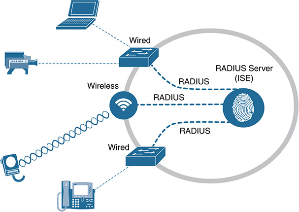
RADIUS is a distributed client/server system that secures networks against unauthorized access. RADIUS was created originally for dial-in user access (hence its name), but it has evolved greatly. RADIUS clients run on all types of infrastructure, such as routers, switches, and wireless controllers. These clients send authentication requests to a central RADIUS or AAA server that contains all user authentication and network service access information. Figure 9-24 shows how the infrastructure connects to the RADIUS server (ISE).
RADIUS is a fully open protocol, distributed in source code format, that can be modified to work with any security system currently available on the market. Cisco supports RADIUS under its AAA security paradigm, and RADIUS has been implemented in a variety of network environments that require high levels of security while maintaining network access for remote users. RADIUS, AAA, and 802.1X port-based authentication all work together harmoniously.
When the authentication request is transmitted to the AAA server, the AAA client expects the authorization result in the reply. RADIUS uses only four message types:
■ Access-Request: Sent from the AAA client to the AAA server, requesting an authentication and authorization.
■ Access-Accept: Sent from the AAA server to the AAA client, providing a successful authentication response. The authorization result is included in this message as an AV Pair, which can contain a VLAN, an access list, or a security group tag (SGT). The section “Dynamic Authorization Privileges” covers these.
■ Access-Reject: Sent from the AAA server to the AAA client, signaling an authentication failure with no authorization privileges granted.
■ Access-Challenge: Sent from the AAA server to the AAA client when additional information is required.
Figure 9-25 illustrates the RADIUS packet format. The fields are transmitted from left to right, starting with the code, the identifier, the length, the authenticator, and the attributes.
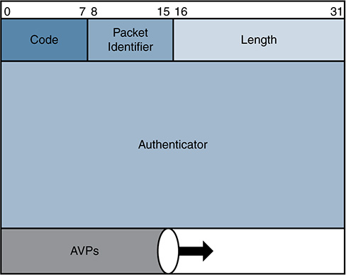
A/V Pairs
The RADIUS Attribute Value pairs (A/V) carry data in both the request and the response for the authentication, authorization, and accounting transactions. When a client is communicating with the AAA server, attributes can be referenced to signify an answer or result. The RADIUS server might be assigning an attribute to the authentication session. This is where the VLAN, downloadable access control list, and SGT are carried back to the access infrastructure. Figure 9-26 illustrates the RADIUS A/V pair format.
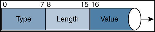
802.1X
The IEEE 802.1X standard defines a client- and server-based access control and authentication protocol that restricts unauthorized clients from connecting to a LAN through publicly accessible ports. The authentication server authenticates each client connected to a switch port and assigns the port to a VLAN before making available any services offered by the switch or the LAN. Until the client is authenticated, 802.1X access control allows only Extensible Authentication Protocol over LAN (EAPOL) traffic through the port to which the client is connected (unless it is configured to allow additional traffic). After authentication is successful, traffic is allowed to proceed through the port.
802.1X operation involves three device roles:
■ Client: The client is the endpoint requesting access to the network, and it responds to requests from the switch. The endpoint must be capable of using 802.1x software, otherwise known as the supplicant.
■ Authentication server: This server executes the authentication of the client by validating the identity of the client and notifying the switch of successful or unsuccessful attempts. The switch acts as a proxy, making the authentication service transparent to the client. RADIUS uses a client/server model in which authentication information is exchanged between the RADIUS server (ISE) and one or more RADIUS clients.
■ Authenticator: The authenticator acts as the proxy between the client and the RADIUS server (for example, ISE). It requests the identity from the client, sends it to the server (ISE) for an authentication decision, and relays the response to the client. As an example, the authenticator could be the LAN switch port, which would encapsulate/decapsulate EAP frames when it communicates with the RADIUS server.
When the switch receives EAPOL frames from the client and relays them to the authentication server, the Ethernet header is stripped and the remaining EAP frame is re-encapsulated in the RADIUS format to be sent to the RADIUS server. The EAP frames are not modified or examined during encapsulation, and the RADIUS server must support EAP within the native frame format. When the switch receives frames from the RADIUS server, the header is removed, leaving the EAP frame, which is then encapsulated for Ethernet and sent back to the client.
Figure 9-27 explores the authentication initiation more closely:

■ During IEEE 802.1x authentication, either the switch or the client can initiate authentication. If the dot1x port-control auto interface configuration command is used on a Cisco switch, the switch initiates authentication when the link state changes from down to up, or periodically as long as the port remains enabled and unauthenticated.
■ The switch sends an EAP-Request/identity frame to the client to request its identity.
■ When it receives the frame, the client responds with an EAP-Response/identity frame.
■ The network device encapsulates the EAP-Response that it received from the host into a RADIUS Access-Request (using the EAP-Message RADIUS attribute) and sends the RADIUS Access-Request to the RADIUS server.
■ The RADIUS server extracts the EAP Response from the RADIUS packet and creates a new EAP Request. It encapsulates that EAP Request into a RADIUS Access-Challenge (again, using the EAP-Message RADIUS attribute) and sends it to the network device.
■ The network device extracts the EAP-Request and sends it to the host.
After authentication is successful, traffic is allowed to proceed through the port.
In some instances, particularly with constrained devices, 802.1X is not supported or might not have enough RAM/flash or software intelligence to install an 802.1X supplicant. In these cases, another authentication method can be used within a port-based authentication framework: MAC address bypass (MAB).
MAC Address Bypass
The MAB feature configures the access infrastructure to authorize clients based on their MAC address. For example, you can enable this feature on IEEE 802.1x ports connected to devices such as printers, or to devices that don’t have the capability to run an 802.1X supplicant. Using this model, the switch sends the RADIUS server an Access-Request frame with the MAC address representing the device’s username and password. This requires an “authorized” MAC address list to be created and installed on the RADIUS server. Figure 9-28 illustrates the MAB exchange flow.
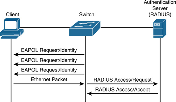
The MAB exchange flow works as follows:
■ If IEEE 802.1x authentication times out while waiting for an EAPOL message exchange and MAB is enabled, the MAB process initiates.
■ The switch uses the MAC address of the client as its identity and includes this information in the RADIUS-Access/Request frame that is sent to the RADIUS server.
■ The authentication server has a database of client MAC addresses that are allowed network access. It compares the request to this database.
■ After the RADIUS server sends the switch the RADIUS-access/accept frame (if authorization is successful), the port becomes authorized.
Flexible Authentication
The IEEE 802.1X Flexible Authentication feature provides a means of assigning authentication methods to ports and specifying the order in which the methods are executed when an authentication attempt fails. Using this feature, you can control which ports use which authentication methods and also control the failover sequencing of methods on those ports.
The IEEE 802.1X Flexible Authentication feature supports three authentication methods:
■ Dot1X-IEEE 802.1X authentication is a Layer 2 authentication method.
■ Mab-MAC-Authentication Bypass is a Layer 2 authentication method.
■ Webauth-Web authentication is a Layer 3 authentication method.
Figure 9-29 illustrates 802.1X and MAB port-based authentication on the infrastructure, communicating with the RADIUS server (ISE).
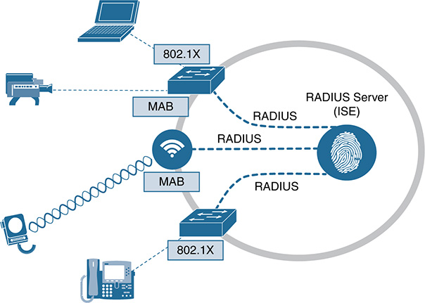
The authentication order sets the default authentication priority. As an example, imagine that you want to configure the switch ports with the default port configuration of trying 802.1X first, and if it fails, subsequently attempt MAB. This is a useful approach because the switch ports can be configured ubiquitously; regardless of the endpoint connection (having an 802.1X supplicant or not), a connection method will be available without administrator intervention. Additionally, a fallback strategy is important to construct. Figure 9-30 illustrates a sample fallback strategy for a non–802.1X endpoint.
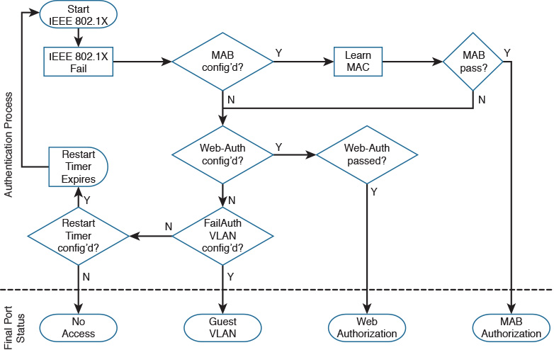
Carefully designing fallback mechanisms is best. Default access profiles are important to the overall NAC policy and must be well planned. Additionally, you should consider having different fallback policies based on the environment and geographical location.
Dynamic Authorization Privileges
This chapter’s identity and authentication sections work hand in hand with this section on authorization. The scope of this book encompasses leveraging automation and orchestration techniques to secure use cases, so here we explore three popular automated solutions, Cisco ISE and TrustSec, AWS policy-based authorization, and manufacturer usage description (MUD). These options all dynamically provide appropriate authorization privileges based on identity, but they do so in very different ways.
Several types of authorization privileges can be granted. Common examples take the form of network access control, others use configuration variables such as QoS parameters, and still others work with actions. We consider the following forms of dynamic authorization privileges as we dive into the various solutions:
■ VLAN assignment
■ Access control lists
■ Security group tags
■ JSON objects
■ Configuration parameters such as QoS
Cisco Identity Services Engine and TrustSec
As mentioned previously in the section “Authentication Methods,” ISE is an integrated architecture approach for both network access and policy constructs. It combines identity, authentication, and authorization using a comprehensive access control solution, and it does so in an automated way by turning ISE and the infrastructure into an SDN-like framework (with ISE acting as the TrustSec controller). Authentication policies and authorization privileges are configured using ISE. When an endpoint is identified via classification, it is then authenticated based on policy and granted the appropriate authorization privileges based on its identity. Those privileges come in three major forms of dynamic authorization: VLANs, access control lists, and security group tags (SGT). Figure 9-31 shows the three forms.
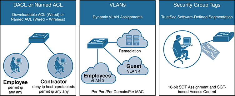
Before we explore the three forms of dynamic authorization, it’s best to quickly discuss the concept RADIUS Change of Authorization (CoA), which is a cornerstone of ISE. RADIUS CoA distributes the authorization privileges to the applicable RADIUS session.
RADIUS Change of Authorization
The RADIUS CoA feature provides a mechanism to change the attributes of an authentication, authorization, and accounting (AAA) session after it is authenticated. When a policy changes or is altered for a user or user group in AAA, an administrator can send the RADIUS CoA packets from the AAA server, such as ISE, to reinitialize authentication and apply the new policy.
CoA Requests
RADIUS CoA requests, defined in RFC 3576 and 5176, are used in a push model. The request originates in the external server for the device attached to the network and enables the dynamic reconfiguration of sessions from external authentication, authorization, and accounting (AAA) servers (such as ISE).
Use the following per-session CoA requests:
■ Session reauthentication
■ Session termination
■ Session termination with port shutdown
■ Session termination with port bounce
■ Security and password
■ Accounting
The model consists of one request (CoA Request) and two possible response codes:
■ CoA acknowledgment (ACK) [CoA-ACK]
■ CoA nonacknowledgment (NAK) [CoA-NAK]
The request is initiated from a CoA client (typically a RADIUS or policy server) and directed to the device that acts as a listener.
CoA Request/Response Code
The CoA Request/Response code can be used to issue a command to the device. The packet format for a CoA Request/Response code, as defined in RFC 5176, consists of the following fields: Code, Identifier, Length, Authenticator, and Attributes in the Type:Length:Value (TLV) format.
The Attributes field carries Cisco VSAs. Figure 9-32 shows the CoA packet format.
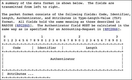
Session Identification
Disconnect and CoA Requests can be sent to a particular session, which makes this solution extremely effective. The device locates the session based on one or more of the following attributes:
■ Acct-Session-Id (IETF attribute #44)
■ Audit-Session-Id (Cisco vendor-specific attribute [VSA])
■ Calling-Station-Id (IETF attribute #31, which contains the host MAC address)
CoA Request Commands
The CoA commands that are supported on the device follow. These must include the session identifier between the device and the CoA client.
■ Bounce host port: Cisco:Avpair=“subscriber:command=bounce-host-port”
■ Disable host port: Cisco:Avpair=“subscriber:command=disable-host-port”
■ Re-authenticate host: Cisco:Avpair=“subscriber:command=reauthenticate”
■ Terminate session: This is a standard disconnect request that does not require a VSA.
Figure 9-33 illustrates the CoA concept.

The CoA flow in Figure 9-33 follows this process:
■ As the endpoint attempts to gain access to the infrastructure, it is met with one of the authentication mechanisms discussed previously (for example, 802.1X or MAB).
■ The switch encapsulates the EAP Response that it received from the host into a RADIUS Access-Request (using the EAP-Message RADIUS attribute) and sends the RADIUS Access-Request to the RADIUS server.
■ This creates the Acct-Session-ID, which is IETF attribute #44.
■ When the RADIUS server responds with the RADIUS Access-Accept, the authorization privileges are also transmitted in the form of a VLAN, a downloadable access control list (dACL), or an SGT.
Example 9-3 shows the CoA via the output of a show authentication session command on the switch. An SGT (0002-0) is the authorization that dynamically gets assigned to the accounting session ID (Acct Session ID).
Example 9-3 SGT Value of 2 Applied to the Acct Session ID Using the CoA Process
Switch# show authentication sessions interface g1/2

            Interface:  GigabitEthernet1/2
          MAC Address:  0050.b057.0104
           IP Address:  10.1.1.112
            User-Name:  employee1
               Status:  Authz Success
               Domain:  DATA
      Security Policy:  Should Secure
      Security Status:  Unsecure
       Oper host mode:  multi-auth
     Oper control dir:  both
        Authorized By:  Authentication Server
          Vlan Policy:  N/A
              ACL ACL:  XACSACLx-IP-Employee-ACL
                  SGT:  0002-0
      Session timeout:  N/A
         Idle timeout:  N/A
    Common Session ID:  C0A8013F0000000901BAB560
      Acct Session ID:  0x0000000B
               Handle:  0xE8000009

Runnable methods list:
       Method   State
       dot1x    Authc Success
VLAN
VLAN assignments and ACLs are great ways of controlling access to a network. However, when a network grows, the challenges of maintaining the security policy grow with them. VLAN assignment based on the context of a user or device is a common way to control access to a network. Figure 9-34 illustrates the dynamic VLAN assignment method.
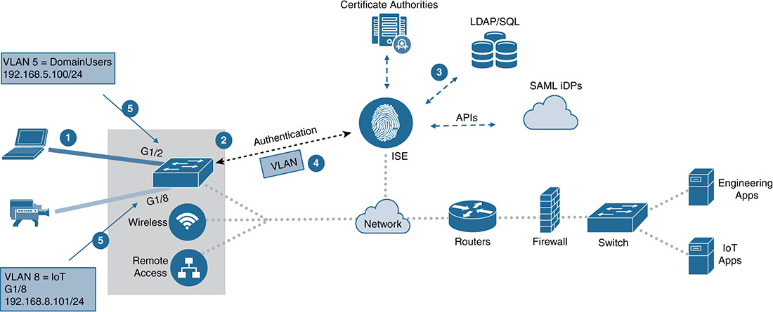
The next steps walk through Figure 9-34:
The user/endpoint attempts to gain access to the network and is challenged by the port-based authentication on the switch (802.1X).
The switch encapsulates the EAP response it received from the host into a RADIUS Access-Request and sends the RADIUS Access-Request to ISE. This process creates the unique RADIUS Acct Session ID.
ISE checks its authorization policy, which dictates the use of an external identity source (in this case, it is Active Directory, where the user’s account information is verified via LDAP). It’s determined that the user has an active account in the Engineering AD group.
When the RADIUS server (ISE) responds with the RADIUS Access-Accept, ISE can return vendor-specific tunnel attributes to the device. Attribute [64] must contain the value “VLAN” (type 13). Attribute [65] must contain the value “802” (type 6). Attribute [81] specifies the VLAN name or VLAN ID assigned to the IEEE 802.1X-authenticated user. Using these attributes, coupled with the RADIUS session ID, is how you can have unique authentication streams.
The camera and the computer both authenticate separately, so they both have unique RADIUS session IDs and thus can be given unique authorization privileges. In this case, the computer is instantiated into VLAN5 and the camera is instantiated into VLAN8.
Figure 9-35 illustrates how to create an authorization profile. This is an example of associating a profile named Domain_user_VLAN, which assigns VLAN = 5.
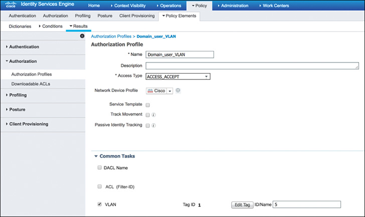
That profile then is simply tied to an authorization policy. The policy is based on simple IF/THEN technology. The rule name is on the left, the middle category shows the conditions that must be met (the IF criteria), and the right column shows the authorization privileges to assign (THEN criteria). The Domain_user_VLAN profile assigns VLAN = 5.
Figure 9-36 illustrates the IoE_Employee policy that associates the authorization profile of Domain_user_VLAN to a set of criteria that must be matched in the middle.
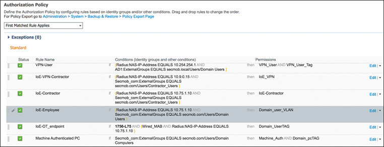
Figure 9-36 Sample Authorization Policy That Links the Authorization Profile Created in Figure 9-35
One of the downsides of using VLANs in this model is that scaling becomes difficult as VLANs are added to switches and wireless controllers. For large organizations that have thousands of access switches, this could be a significant number of VLANs, all of which ultimately need to be maintained in access lists. A full staff might be required just to maintain the rule sets.
Additionally, this approach assumes that VLANs are trunked throughout, which might not be the case in many organizations.
Access Control Lists
An additional method of controlling access is to use access control lists (ACL).
These can be locally defined ACLs that are called by using the Filter-ID RADIUS attribute. Alternatively, they can be downloadable access control lists (dACL), in which the entire ACL is defined on the Cisco ISE and downloaded to the switch, and then applied ingress on the port (or virtual port) that the user or device is connecting to the network.
dACLs provide a better operational model because the ACL must be updated only once. Additionally, fewer ACEs are required when the ACL is applied to a switch port instead of being applied to a centralized location.
Note Cisco switches perform source substitution on these ACLs. Source substitution allows the use of the any keyword in the source field of an ACL; this gets replaced with the actual IP address of the host on the switch port.
ACLs get loaded into and executed from ternary content addressable memory (TCAM). Access layer switches have a limited amount of TCAM, which is usually assigned per application-specific integrated circuit (ASIC). Therefore, the number of ACEs that can be loaded depends on several factors, such as the number of hosts per ASIC and the amount of free TCAM space.
With that limited amount of TCAM, ACLs cannot be overly large, especially when the access layer could be a mixture of different switches, with each switch having a different level of TCAM per ASIC. Best practice dictates keeping ACEs to less than 64 per dACL, but this might need to be adjusted for the specific environment. These restrictions and scalability issues led Cisco to create the SGT, discussed next. Figure 9-37 illustrates the dACL form of dynamic authorization.
The CoA flow is the same as the VLAN CoA flow discussed earlier. However, instead of ISE providing a VLAN, this approach provides dACLs to the switch that get instantiated ingress on the switch port.

We also show a wireless connection from the camera, in which the wireless controller has a connection to ISE over RADIUS. All network access devices are connected to ISE over RADIUS, with the intent of centralizing AAA for the whole network. Cisco’s Wireless LAN Controller (WLC) supports the use of the access list CoA a bit differently. Instead of downloading the aCL (dACL), the WLC supports preconfigured ACLs. ISE simply sends the ACL name, which was preconfigured in the WLC.
The authorization profile created for the dACL is handled with the same creation steps listed previously. However, instead of choosing a VLAN as the method for authorization, the dACL syntax is created (see Figure 9-38).

That profile then is tied to the permissions in the authorization policy. The IoE-Employee profile equals a CoA of the dACL shown in Figure 9-37.
Figure 9-39 ties everything together.
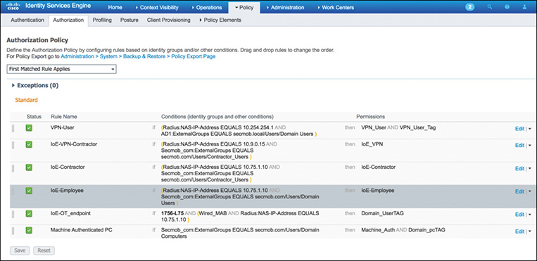
Figure 9-39 Sample Authorization Policy Linking the Authorization Profile Created in Figure 9-38
TrustSec and Security Group Tags
The Cisco SGT architecture, known as TrustSec, differs from the previous two dynamic authorization methods. Those mechanisms are based on network topology, whereas Cisco TrustSec policies use logical groupings (group-based policy). These groupings provide true role-based access control. By classifying traffic according to the contextual identity of the endpoint instead of its IP address, the Cisco TrustSec solution enables more flexible access controls for dynamic networking environments. ISE answers the who, what, when, where, and how, and associates the aggregated information to a role (which is ultimately represented by the tag). Figure 9-40 shows an example of the categories ISE couples to form a role; the SGT represents the role.
TrustSec decouples access entitlements from IP addresses and VLANs and instead leverages this tag. This approach simplifies security policy maintenance tasks, lowers operational costs, and allows common access policies to be consistently applied to wired, wireless, and VPN access. ISE provides three main benefits:
■ Role-based access control based on context, using the SGT
■ Software defined
■ Dynamic segmentation, independent of topology (decouples policy from VLAN and IP addressing)

The Security Group Tag
An SGT is a 16-bit value that ISE assigns to the endpoint’s session upon login. The network infrastructure views the SGT as another attribute to assign to the session and inserts the Layer 2 tag into all traffic from that session.
The SGT is analogous to a physical security badge—it is the logical version. For example, someone might walk into a secure facility, present a card key at the front door, and gain access. Then perhaps that person successfully uses the same card key to enter an office on the third floor but is denied access when attempting to use the card key to enter the server room. The SGT is the logical representation of that card key. The SGT represents the role and attaches to the network traffic at ingress (inbound into the network); the access policy based on the tag can be enforced elsewhere in the infrastructure (in the data center, for example). Switches, routers, firewalls, web proxies, and more use the SGT to make forwarding decisions. This tag follows a person anywhere. If someone connects to a conference room in Chicago, that person is examined by ISE, authenticated, and provided an SGT. Likewise, if someone connects to an SSID in an office in the United Kingdom, that person is examined by ISE, authenticated, and provided an SGT. If someone attempts to use remote access to enter the network, the firewall also connects to ISE over RADIUS, just as in the other infrastructure, and is then examined, authenticated, and ultimately provided an SGT. Regardless of where someone connects from, ISE answers the who, what, when, where, and how, and then provides the appropriate access based on identity.
Software Defined
ISE is the TrustSec controller; hence, policy is managed centrally and provisioned automatically based on entry into the network. Policy is invoked anywhere the endpoint attempts connection (wired, wireless, remote access). This reduces risk exposure because policy does not have to be created in every LAN switch or wireless controller, nor do static ACLs need to be created (static ACLs do not scale). Instead, policy is created in a central location, which makes an admin’s job easier. Figure 9-41 illustrates the TrustSec controller concept.
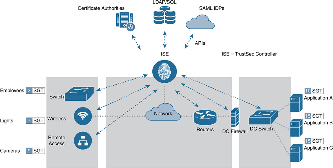
Dynamic Segmentation Based on RBAC
Segmentation is based on the role, which is based on context. Instead of creating policy simply based on IP address, we can leverage username, device type, AD groups, certificates, location, time, and so on for a far more comprehensive and granular policy. ISE couples that information, associates it with a role, and tags the role (SGT); now the policy can be enforced in the network based on tags. When someone receives the SGT, this not only grants someone access privileges, but it also serves as a dynamic form of segmentation recognized by large standards bodies (such as the payment card industry [PCI]) auditors. Figure 9-42 illustrates how to leverage SGTs for dynamic segmentation.
Cisco TrustSec classification and policy enforcement functions are embedded in Cisco switching, routing, wireless LAN, and firewall products.
The goal of Cisco TrustSec technology is to assign an SGT to the user or device traffic at ingress (inbound into the network) and then enforce the access policy based on the tag elsewhere in the infrastructure (in the data center, for example). Switches, routers, and firewalls use this SGT to make forwarding decisions.

The next section explores the TrustSec framework and architecture more closely.
TrustSec Enablement
A TrustSec architecture accomplishes three major functions: classification, propagation, and enforcement (see Figure 9-43).
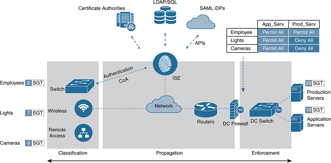
Classification
To leverage SGTs within an infrastructure, devices must support SGTs. All Cisco switches and wireless controllers embedded with Cisco TrustSec technology support the assignment of SGTs, which is referred to as classification.
An SGT can be assigned dynamically or statically. Figure 9-44 illustrates both dynamic and static SGT assignment.
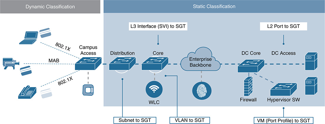
Dynamic classification occurs in an authentication sequence, via 802.1x, MAB, or web authentication. When authentication is not available, static classification methods are necessary. The process of examining the endpoint, comparing the data against a rule set, and assigning the SGT is known as classification.
Figure 9-45 illustrates dynamic SGT assignment on the LAN switch.
In static classification, the tag maps to something (an IP, subnet, VLAN, or interface) instead of relying on dynamic authorization from Cisco ISE. These classifications are then transported deeper into the network for policy enforcement. There are more ways of statically defining SGTs, but these are beyond the scope of this chapter.
Figure 9-46 illustrates static SGT assignment on the LAN switch.
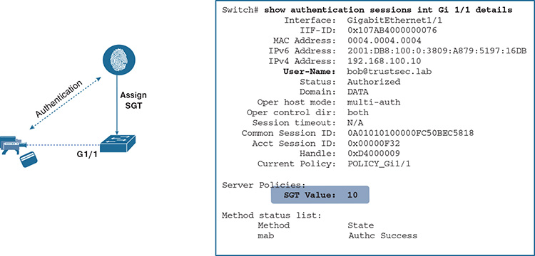

Propagation
Now that the SGT is assigned to the user or endpoint’s session, the next step is to communicate the tag upstream to TrustSec-enabled devices, which enforce policy based on SGTs. This communication process is defined as propagation. Two major methods handle propagation or transport of the SGT/IP binding:
■ Inband: This method carries the tag in the data path. Methods include Ethernet, MACsec, LISP/VxLAN, IPSEC, DMVPN, and GetVPN.
■ Out of band using SGT Exchange Protocol (SXP): IP-to-SGT binding information is shared over a control protocol if no SGT information is in the data plane (inband method).
Figure 9-47 shows an example of an access switch that has native tagging. The packets get tagged on the uplink port and through the infrastructure. The figure also shows a non-inline-capable switch that uses SXP to update the upstream switch. SXP is a control protocol for propagating IP-to-SGT binding information across network devices that do not have the capability to tag packets, so the SGT can still be used and enforced upstream even if the intermediate devices do not support it.

Inline tagging capabilities should be used throughout whenever possible. Using this method, the top access layer is capable of applying the SGT to the Layer 2 frame as it is sent across the wire to the upstream host. Each upstream host replicates the procedure and the tag is present throughout the entire infrastructure. The bottom non-inline-capable switch can perform classification, so it can attach an SGT to an IP address but does not possess the ASIC to embed the SGT within the Ethernet frame (hence the term non-inline-capable). Instead, this switch leverages the SXP protocol to transmit the IP–SGT binding information (its classification) to the upstream switch, where the SGT is inserted into the Ethernet frame. This creates a situation in which both methods transmit the IP–SGT binding information upstream for potential enforcement. Consider some facts about SXP:
■ Supports open protocol (IETF-Draft) and ODL
■ Has two roles: speaker (initiator) and listener (receiver)
■ Supports single-hop SXP and multihop SXP (aggregation)
■ Uses MD5 for authentication and integrity check
■ ISE 2.0 can be a Speaker and Listener
Inline Tagging Mediums (Ethernet and L3 Crypto)
Several inline tagging media exist. The scenario discussed previously embeds the SGT (Cisco metadata) in an Ethernet Layer 2 frame. Figure 9-48 illustrates the Ethernet inline tagging format.

■ SGT is embedded within Cisco metadata (CMD) in the Ethernet Layer 2 frame.
■ Switches that support the capability process at line rate.
■ Optionally, CMD can be protected with MACsec (802.1AE).
■ L2 frame impact: ~20 bytes
■ 16-bit field = 64K tag space
■ This is the most efficient and scalable method for propagation with LAN/DC.
Another supported medium is the Layer 3 inline method, which is the crypto transport for SGT. Cisco Meta Data (CMD) uses Protocol 99 and is inserted at the beginning of the ESP/AH payload. Figure 9-49 illustrates the crypto transport frame format.
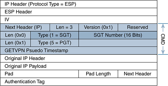
Enforcement
Now that we have discussed how security groups get assigned (classification) and how they can be transmitted across the network (propagation), we need to look at the third pillar: enforcement. Traffic can be enforced based on the tag in multiple ways, but we can divide them into two major types:
■ Enforcement on a switch: Security Group Tag ACL (SGACL)
■ Enforcement on a firewall: Security Group Firewall (SGFW)
SGACL
SGACLs provide several benefits, but one of their primary advantages is that they facilitate capturing and maintaining policy intent throughout the network diameter. Most management and orchestration offerings take IP/port object references and render them as IP information and ACLs to enforcement points.
IP ACLs do not describe the intent of policy in the device or in the telemetry produced by the device. For example, IP addresses can change, particularly based on location or medium used. If company policy dictates that a contractor asset should communicate with application A only on port X, how can that be effectively enforced with ACLs throughout the full network diameter? Beyond that, how can the policy be effectively enforced on the wired infrastructure, the wireless infrastructure, the remote access pods, and so on? Even if ACLs are created in various discontiguous spots (which heightens risk exposure and increases the chance for error) it would still be necessary to equate IP to users to get useful telemetry. Using SGTs and SGACLs, we can maintain intent and place that intent into the policy on enforcement points throughout the network diameter. Another benefit to SGACL use is the consolidation of access ACEs and the operational savings of maintaining those traditional access lists.
Consumer/Provider Matrix
SGACLs are a policy enforcement mechanism through which the administrator can control the operations users perform, based on security group assignments and destination resources. Policy enforcement within the TrustSec domain is represented by a permissions matrix (consumer/provider matrix). This means that business policy can be translated into technical rules that then can be enforced electronically throughout the network. ISE brings the consumer/provider communications matrix discussed in Chapter 2 to fruition.
The communication matrix is essentially a digital reflection of business policy. It is based on a source/destination tag. Tags comprise a role, and the role consists of the criteria we discussed earlier (username, device type, AD group, certificate, location, access medium, time of day, and so on). ISE can examine endpoints, authenticate them, and place them into the proper groups by assigning the SGTs. Figure 2-9 in Chapter 2 shows a sample general consumer/provider communications matrix.
The ISE consumer/provider matrix is similar to the communications matrix. The SGACLs maintain policy intent throughout the infrastructure. Now creating policy is as simple as selecting the appropriate tags that represent the groupings. This is laid out as follows:
■ Source SGT: Positioned in the left-side vertical column
■ Destination SGT: Positioned horizontally across the top
Figure 9-50 illustrates the ISE communication matrix.
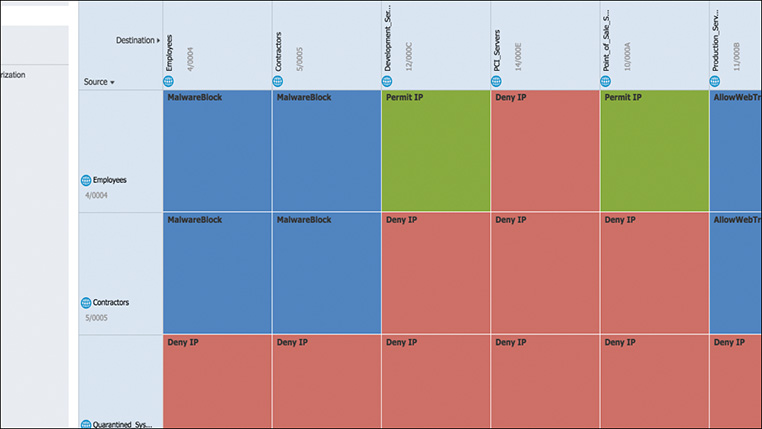
To create policy between employees (SGT4) and production servers (SGT11), we can simply locate the respective source and destination groups and attach the allowed communication list (SGACL). Each SGACL is defined once, as with the SGT itself, so we can simply select it from a drop-down when creating policy.
Figure 9-50 shows a policy called AllowedWebTraffic; Figure 9-51 demonstrates how to create the SGACL.
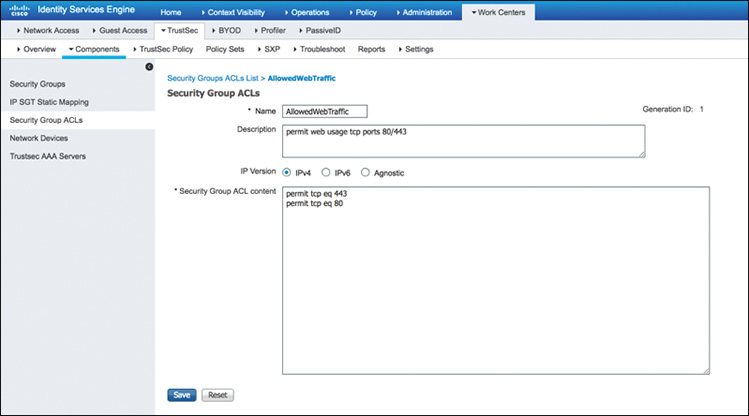
Figure 9-52 illustrates selecting the AllowedWebTraffic ACL for a consumer/provider policy.

SGACL for North–South and East–West
SGACLs can be deployed as either north–south or east–west. North–south refers to classifying a user or device at the access layer but then handling enforcement with the SGACL upstream (perhaps at infrastructure in the data center). For example, a guest entering the access layer is assigned a Guest SGT; any traffic with a Guest SGT is dropped if it tries to reach a server with financial data. This requires configuring both ISE and the participating data center switches to communicate and download the IP-to-SGT bindings that arise from endpoint entry into the network. The infrastructure can then download the SGACLs that apply to the egress policies.
Figure 9-43, shown previously, illustrated an example of north–south enforcement. It requires configuring both ISE and the participating data center switches to communicate.
East–west refers to an SGACL protecting resources that exist on the same switch. For example, you might want to restrict a contractor endpoint from reaching an HMI, even though both might be in the same VLAN on the same switch. This is referred to as microsegmentation, the capability to provide segmentation within the same VLAN using the SGT as both the enforcement and segmentation method. Other vendors struggle to address this use case, and it is a fairly important one. Figure 9-53 illustrates how SGACLs can perform microsegmentation.
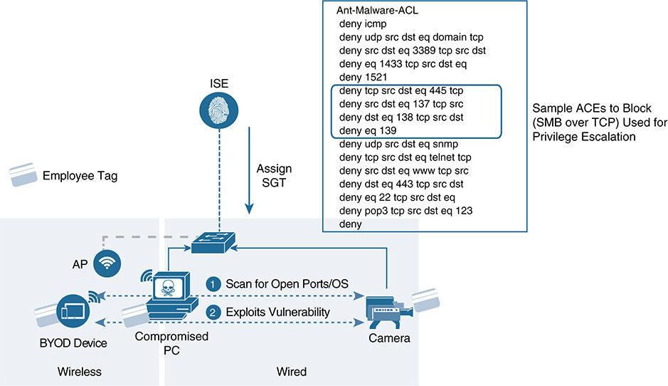
This policy is a Malware Block policy. Refer to the ISE TrustSec consumer/provider matrix in Figure 9-50, and look at the policy created from SGT 4–Employees to SGT 4, named MalwareBlock. That policy is an ACL that was created to prevent lateral movement within one’s own VLAN. It essentially mimics the behavior of malicious software and malware. A typical behavior pattern of malware is to run a quick scan to learn the hosts on the local segment and then run a port scan to learn what ports are open on the available hosts. Malware essentially tries to replicate itself to another host. To invoke this policy, you simply create the SGACL once and attach the name MalwareBlock to it; now it is available to be attached in the communications matrix. When an employee connects and is examined by ISE, that employee will be granted the applicable SGT based on their identity, and the SGACL will be tied ingress to the switch port. This negates the malicious behavior within the VLAN itself. Figure 9-54 illustrates how to create the SGACL rule set.
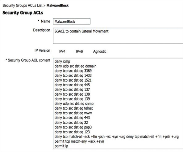
Automation of SGACLs and Dynamic Segmentation
The “RADIUS Change of Authorization” section discussed how SGTs get dynamically assigned ingress on the switch port upon entry into the network via CoA. A similar process, from an automation perspective, happens for SGACLs. The infrastructure and ISE must be configured so that they communicate. Figure 9-55 shows the ISE configuration; pay particular to the bottom part, under Device Configuration Deployment. That setting allows ISE to push the IP-to-SGT bindings to the infrastructure along with the SGACLs that apply to the egress policies. Figure 9-55 shows an example of creating ISE TrustSec communication to a Cisco IE4000 switch.
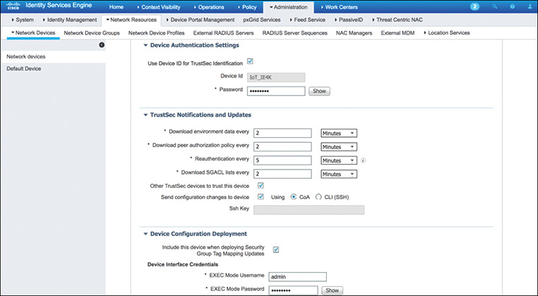
In summary, ISE plays a large role in the IAM process, combining endpoint profiling with AAA, enforcement, posture, and segmentation into an integrated architecture. ISE serves as the TrustSec controller for the infrastructure, and it works in conjunction with switches, wireless controllers, routers, and firewalls to do the following:
■ Apply consistent policy across the network diameter: The infrastructure is connected to ISE over RADIUS. This delivers the capability to deploy policy from a single location that represents the consumer/provider communications matrix. This is accomplished dynamically by examining each endpoint as it attempts to gain access to the network, authenticating it, and ultimately providing the appropriate levels of access privileges in the form of a tag based on identity.
■ Reduce risk: Policy no longer needs to be configured on each switch, wireless controller, and so on. Instead, we can simply point the infrastructure to ISE and configure policy on it. Risk also is reduced by using the unique microsegmentation technique to restrict lateral movement.
■ Streamline compliance: Access to regulated applications is easily controlled using group-based policies. SGTs can reduce the scope of compliance (they are commonly used for HIPAA, DFARS, and PCI).
■ Lower operational expenses: SGTs can be deployed without touching the current VLAN assignments or IP addressing scheme. TrustSec and SGTs can be deployed right over the top. According to an analysis by Forrester Consulting, customers who used TrustSec software-defined policy and segmentation in production reduced operational costs by 80 percent.
Manufacturer Usage Description
The method by which devices communicate can be captured and placed into a profile. This profile then can be referenced for modeling, as a “constant” in behavior analysis, or for a simple manufacturer usage description (MUD). Devices typically have a specific purpose for their use, which means all other purposes are not intended. The MUD Internet draft uses manufacturer to simply refer to the entity or organization that states how a device is to be used. The key points are that the device itself is expected to serve a limited purpose and that an organization in the supply chain of that device takes responsibility for informing the network about that purpose. According to the MUD Internet draft, the MUD concept is intended to address certain challenges:
■ Substantially reduce the threat surface on a device entering a network to support only communications intended by the manufacturer.
■ Provide a means to scale network policies to the ever-increasing volume of devices in the network.
■ Provide a means to address at least some vulnerabilities in a way that is faster than the time needed to update systems. This is particularly true for systems that are no longer supported by their manufacturer.
■ Keep cost to a minimum.
Finding a Policy
The transaction begins when the device emits a Uniform Resource Locator (URL) [RFC 3986]. This URL serves two functions: It classifies the device type and provides a means of locating a policy file.
According to the MUD Internet draft, three ways are defined for emitting the MUD URL.
■ DHCP option: A DHCP client informs the DHCP server. The DHCP server can take further actions, such as retrieve the URL or pass it along to a network management system or controller.
■ X.509: The IEEE has developed IEEE 802.1AR, which provides a certificate-based approach to communicate device identity variables that itself relies on RFC 5280. The MUD URL extension is noncritical, as required by IEEE 802.1AR. Various means can be used to communicate that certificate, including Tunnel Extensible Authentication Protocol (TEAP).
■ LLDP: A Layer 2 frame (LLDPDu) can be used by a station attached to a specific LAN segment to advertise its identity and capabilities.
Policy Types
When the MUD URL is resolved, the MUD controller retrieves a file that associates its configuration, which contains its allowed communication. The manufacturer can specify either certain hosts for cloud-based services or certain classes for access within an operational network. An example of a class might be devices of a specified manufacturer type, with the manufacturer type itself indicated by the authority of the MUD URL. Another example might be to allow or negate local access. Policies can be singular or aggregated. The following are some examples:
■ Allow access to host controller.example.com with QoS AF11
■ Allow access to devices of the same manufacturer
■ Allow access to and from controllers that need to speak COAP
■ Allow access to the local DNS/DHCP
■ Deny all other access
Files retrieved are intended to be closely aligned to existing network architectures and make use of YANG [RFC 6020] because of the time and effort spent to develop accurate models for use by network devices. JSON is used as a serialization for compactness and readability, relative to XML.
The YANG modules specified in the draft are extensions to the model that allow a manufacturer to specify classes of systems that are necessary for the proper function of the device. Two modules are specified. The first module identifies a means for domain names to be used in ACLs so that devices that have their controllers offsite or in the cloud can be appropriately authorized with domain names. DNS is the best option because of IP address changes.
The second module abstracts away IP addresses into certain classes that are instantiated into actual IP addresses through local processing. Through these classes, manufacturers can specify how the device is designed to communicate so that network elements can be configured by local systems that have local topological knowledge. In other words, the deployment populates the classes that the manufacturer specifies. According to the draft, the abstractions are as follows:
■ Manufacturer: A device made by a particular manufacturer, as identified by the authority component of its MUD-URL
■ my-manufacturer: Devices that have the same authority section of their MUD-URL
■ Controller: A device that the local network administrator admits to the particular class
■ my-controller: A class associated with the MUD-URL of a device that the administrator admits
The manufacturer classes can be easily specified by the manufacturer, whereas controller classes are initially envisioned to be defined by the administrator. Because manufacturers are unaware of who will be consuming their products and how, it is important for functionality referenced in usage descriptions to be ubiquitous and, therefore, mature. Only a limited-subset YANG-based configuration is permitted in a MUD file.
The MUD Model
A MUD file consists of a JSON-based document in a YANG model. For the purposes of MUD, the elements that can be modified are ACLs augmented by this model. The MUD file is limited to the serialization of a small number of YANG schema.
Publishers of MUD files must not include other elements and must contain only information relevant to the device being described. Devices parsing MUD files must cease processing if they find other elements.
The module is structured into three parts:
The first container holds information that is relevant to the retrieval and validity of the MUD file itself.
The second container augments the access list to indicate the direction in which the ACL is to be applied.
The final container augments the matching container of the ACL model to add several elements that are relevant to the MUD URL or that are other otherwise abstracted for use within a local environment.
Example 9-4 shows the three parts of the module.
module: ietf-mud
       +--rw meta-info
           +--rw last-update?         yang:date-and-time
           +--rw previous-mud-file?   yang:uri
           +--rw cache-validity?      uint32
           +--rw masa-server?         inet:uri
           +--rw is-supported?        boolean
     augment /acl:access-lists/acl:acl:
        +--rw packet-direction?   direction
     augment /acl:access-lists/acl:acl
             /acl:access-list-entries/acl:ace/acl:matches:
        +--rw manufacturer?          inet:host
        +--rw same-manufacturer?     empty
        +--rw model?                 string
        +--rw local-networks?        empty
        +--rw controller?            inet:uri
        +--rw my-controller?         empty
        +--rw direction-initiated?   direction
Figure 9-56 shows an example of an endpoint emitting a URI string via one of the three methods. The network device queries that URL to find the associated policy and the site returns the abstracted XML to the controller based on YANG. This allows a more specific policy to be instantiated on the access device.

Figure 9-56 Example Illustrating More Specific Configuration Instantiated on Access Infrastructure via MUD Process
Figure 9-57 walks through the automated flow from the endpoint’s linkup, through the provisioning process and ultimately to the appropriate configuration on the access device.
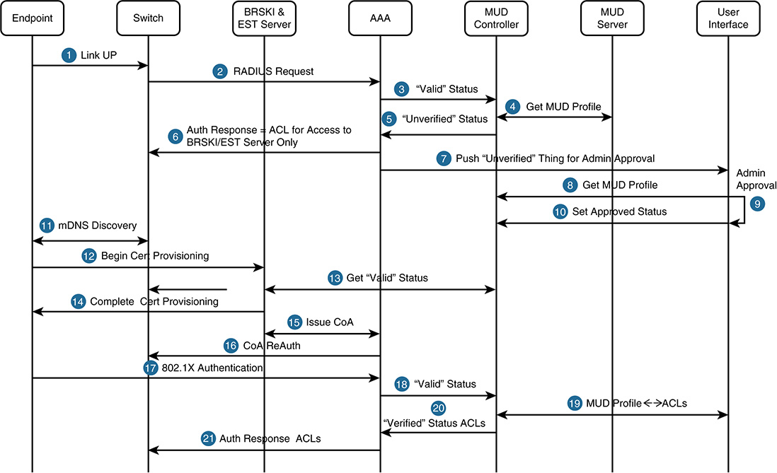
The first couple steps here are nearly identical to the flows discussed in the earlier authentication section under RADIUS/802.1X/MAB.
■ In step 4, the MUD controller attempts to retrieve the MUD profile. However, the device has not been approved yet, which produces the Unverified status in step 5.
■ Step 6 shows the AAA server sending an ACL to the switch, granting permissions to communicate with the BRKSI/EST server only for provisioning. The AAA server also sends a request for the device to be admin approved.
■ After the administrator grants approval, the endpoint is allowed to commence certificate provisioning with the BRSKI/EST server (step 12).
■ When the provisioning is complete, the BRSKI/EST server communicates with the AAA server, and the AAA server sends the CoA command via RADIUS.
■ The process from step 17 onward is similar to the RADIUS authentication/authorization step discussed earlier. The endpoint now has the proper certificate to present for authentication.
■ In step 19, the MUD controller can leverage the fingerprint of the device using its certificate and can retrieve the appropriate configuration variables from the MUD server. The configuration applies to the way that device is intended to communicate, reducing overall risk exposure and maximizing an administrator’s OPEX.
■ The access privileges are relayed back to the switch in the form of ACLs, granting the endpoint the appropriate privileges based on its identity.
AWS Policy-based Authorization with IAM
AWS leverages policy-based authorization techniques coupled with its use of IAM. Before exploring how that works, we need to look at the major components. Figure 9-58 illustrates these AWS security and identity components.
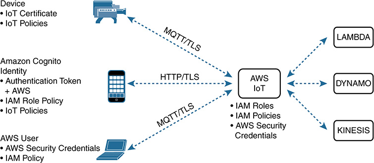
AWS supports four types of identity principles for authentication:
■ IAM users, groups, and roles
■ X.509 certificates
■ Amazon Cognito identities
■ Federated identities
These identities can be used with web, mobile, or desktop applications. They can even be used by a user executing AWS IoT CLI commands. AWS IoT devices typically use X.509 certificates, whereas mobile applications use Amazon Cognito identities. Web and desktop applications use IAM or federated identities. CLI commands use IAM.
We have already explored the use of X.509 certificates in detail. Next we discuss Amazon Cognito and its use of IAM users, groups, and roles.
Amazon Cognito
Amazon Cognito allows us to leverage our own identity provider (iDP) or other popular iDPs, such as those for Google or Facebook. The idea is to exchange a token from our iDP for AWS security credentials. The credentials represent an IAM role and can be used with AWS IoT.
AWS IoT extends Amazon Cognito and allows us to attach policies to Amazon Cognito identities. A policy can be attached to Amazon Cognito and provide fine-grained permissions to an individual user of an AWS IoT application. This makes it possible to assign permissions between specific customers and their devices.
AWS Use of IAM
Three categories make up the standard mechanisms for managing identity and authentication in AWS. The categories can be used to connect to AWS IoT HTTP interfaces using the AWS SDK and CLI.
■ Users
■ Groups
■ Roles
IAM roles allow AWS IoT to access other AWS resources in an account on someone’s behalf. For example, a device can publish its state to a DynamoDB table, and IAM roles allow AWS IoT to interact with Amazon DynamoDB.
Policy-based Authorization
Policy-based authorization grants access privileges to a user or endpoint based on its authenticated identity. An authenticated identity is used by mobile, web, device, and desktop applications. The identity can execute only AWS IoT operations that it is provided via policy.
Both AWS IoT policies and IAM policies are used with AWS IoT to control the operations an identity (also called a principal) can perform. The policy type used depends on the type of identity being used to authenticate with AWS IoT.
AWS IoT policies are attached to X.509 certificates or Amazon Cognito identities. IAM policies are attached to an IAM user, group, or role. If you use the AWS IoT console or the AWS IoT CLI to attach the policy (to a certificate or Amazon Cognito Identity), you can use an AWS IoT policy. Otherwise, use an IAM policy.
Policy-based authorization provides control over what a user, device, or application can execute in AWS IoT. For example, consider a device connecting to AWS IoT with a certificate. That device can be granted access to all MQTT topics or restricted to a single topic. Figure 9-59 shows an example of policy-based authorization.

Policy-based authorization provides a JSON document that has an effect, an action, a principal, and a substitution. Figure 9-60 shows a sample policy-based authorization using JSON.

As Figure 9-60 shows, AWS IoT policies are JSON documents. They follow the same conventions as IAM policies. AWS IoT supports named policies, so many identities can reference the same policy document. Named policies are versioned to allow for simple rollback procedures.
AWS IoT defines a set of policy actions that describe the operations and resources to which access can be granted or denied:
■ iot:Connect permission connects to the AWS IoT message broker.
■ iot:Subscribe represents permission to subscribe to an MQTT topic or topic filter.
■ iot:GetThingShadow represents permission to get a Thing Shadow.
A Thing Shadow is a JSON document that stores and retrieves current state information for a “thing,” regardless of whether it is currently connected to the Internet.
AWS IoT policies facilitate controlling access to the AWS IoT data plane. The AWS IoT data plane consists of operations that connect to the AWS IoT message broker, send and receive MQTT messages, and get or update Thing Shadows. One or more IoT policies can be attached to an identity (such as a certificate). This is an effective and scalable method for controlling resources that a device can access.
Accounting
The final technology in the AAA framework is accounting, which measures and keeps track of the resources a user consumes while accessing the network. This data is important for understanding behavior and is also critical for audit and compliance reasons. RADIUS accounting packets are generated from the infrastructure, such as LAN switches, wireless LAN controllers, and firewalls. These packets can include the amount of data sent or received while on the network, coupled with associated time periods. Accounting packets also can help determine usage information and session statistics for parent functions such as billing and trend analysis.
The AAA functionality, including accounting, is often provided by a dedicated server running AAA functions. To complete the AAA framework, we next look at an example of leveraging ISE for accounting.
How Does Accounting Relate to Security?
RADIUS accounting and other logging mechanisms provide the capability to track usage, which can be applied to both user and administrator usage. Accounting packets are important in detecting and preventing malicious activity. This data is used for investigative techniques such as problem identification, tracking, alerting, and overall behavior analysis. Creating an accounting framework is imperative for a successful pass against a compliance audit. Depending on the industry, are several overarching compliance standards outline specifications that should be met.
To provide an example, the North American Electric Reliability Corporation critical infrastructure protection plan (NERC CIP) is a set of requirements designed to secure the assets required to operate North America’s bulk electric system. It consists of nine standards, with several requirements underneath each standard. Under NERC CIP, entities are required to identify critical assets and then define policies for providing access to the assets, monitoring the assets, editing configurations, and executing a risk analysis against them. Those tasks represent only a portion of what is required for compliance. The NERC CIP requirements are clearly laid out and fairly comprehensive, so companies in this vertical often leverage them as a standard when creating their own framework.
Using a Guideline to Create an Accounting Framework
NERC CIP 007-R5 and its associated subcategories dictate enabling different types of accounts and audit logs to ensure proper audit trails. R5.1 starts to drill into making sure individual and shared accounts are created and remain consistent with the “need to know” concept for work functions performed.
Taking CIP 007-R5 5.1 into consideration, first an access account hierarchy is created (such as Super Admins, Sys Admins, and so on). Each functional category is documented along with its applicability to the organizational structure. A common approach is to start with creating the top-level admin structure and then work down, based on functional categories. Along the way, the principle of least privilege applies at each level (as the requirement states, this is based on “need to know”). The principle of least privilege (POLP) grants users the minimum privileges required to accomplish their tasks and allow “normal functioning.”
Having unique usernames and passwords is critical for auditing purposes. Figure 9-61 illustrates creating a local sys_admin account on ISE.

Authorization permissions are separated into two categories, data and menu access. Data permissions grant permissions to the following:
■ User identity groups
■ Admin groups
■ Device types
■ Locations
■ Endpoint identity groups
Menu access permissions determine which menus the administrator has the capability to access. See Figure 9-62 for sample menu access permissions.

Meeting User Accounting Requirements
NERC CIP 007-R5 5.1.2 dictates the different types of audit logs that should be enabled to ensure the proper level of detail for audit trails. The more specific you can get, the more granular the audit can be (attaching the username to the event type along with date and time, for example). Figure 9-63 shows how the ISE audit logs are broken into categories. To meet the comprehensive requirements of NERC CIP, most of these categories have been enabled.

NERC CIP mandates auditing for both administrators and users. ISE has an extensive selection of reports that can be run, with results categorized in whatever way is most useful. Figure 9-64 illustrates the current active session directory, to quickly show which sessions are currently active, the date/time of connection, their usernames, where they authenticated from, how they authenticated, what type of device they are using, and more. Although this is a lab setup, the Identity category on the far left is purposely cut off, for security reasons.
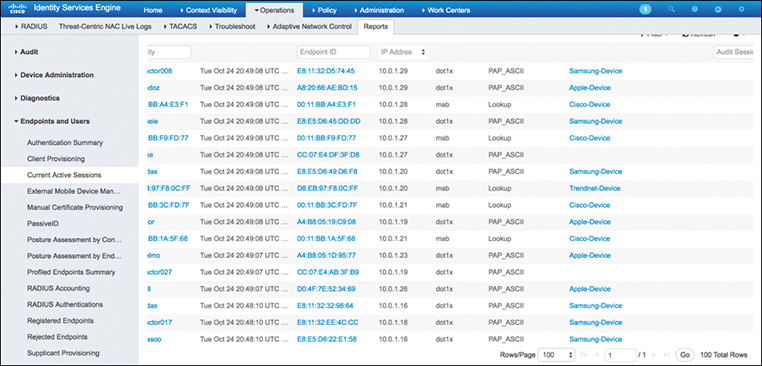
Another good example of a user report is the authentication summary (see Figure 9-65).
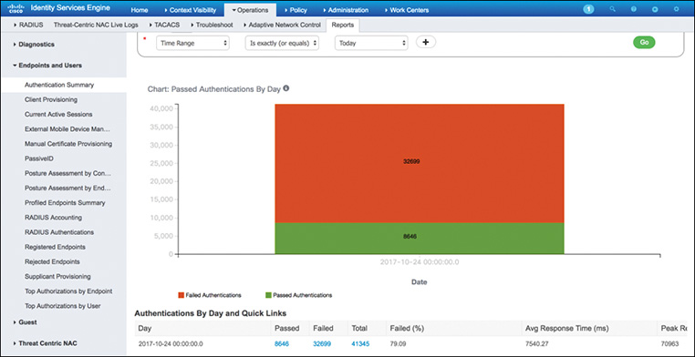
Proper accounting practices assist with compliance, aid in troubleshooting tasks, and provide insight into security issues. Leveraging a comprehensive framework such as NERC CIP as a guideline provides a comparison to ensure that the organization’s approach has sound footing. Note that every compliance audit is different, as is the approach each auditor takes. Using an AAA server such as ISE, which can address multiple requirements without separate solutions, can make jobs of both administrators and auditors a bit easier.
Scaling IoT Identity and Access Management with Federation Approaches
Scaling Identity and Access Management (IAM) is critical to the successful evolution of IoT. In the past, IAM predominantly focused on enterprise-based use cases that involved granting access to applications. Today it has evolved to encompass IoT-based use cases and associated identity management. In contrast to the enterprise-based application access, customer and IoT IAM enables access to data across people, devices, and myriad applications.
This evolution has required the industry to revisit requirements and adjust for IoT IAM. The organizations that are attempting to retrofit their current workforce IAM solutions to address new IoT use cases are quickly seeing limitations. IoT IAM platforms that are considering federation techniques and setting up a circle of trust around an identity provider are better suited to address the unique requirements for security-, privacy-, and policy-based authorization techniques on a larger scale. Many of the federation techniques we discuss later involve a token-based framework that uses tokens instead of usernames and passwords. This increases exponentially the scalability factor because tokens and scopes can be managed independently from the device. Companies that choose to adopt purpose-built IAM platforms that utilize federation techniques (instead of attempting to retrofit) will be able to offer secure transactions without sacrificing user experience. This could ultimately accelerate IoT adoption. Figure 9-66 illustrates the basic difference between enterprise and IoT IAM.
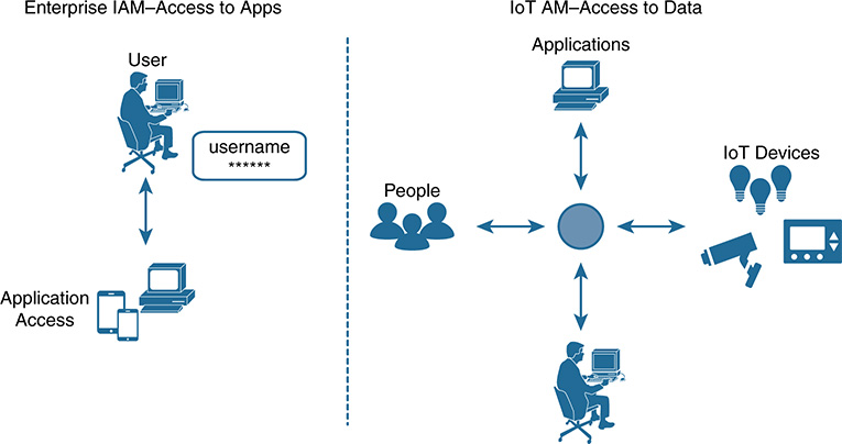
IoT IAM Requirements
Before we look at some of the token-based solutions and their advantages, we must explore the IoT IAM requirements that have sparked the need for such solutions.
■ Flexible authentication: An IoT endpoint itself varies, from refrigerators, to light bulbs, to wearables, to manufacturing robots. Authentication requirements need to be tailored to adapt to different use cases.
For example, a simple sensor device such as a smart refrigerator might require a single method of authentication in which the device confirms the user. A smart vehicle might have a higher security profile because of increased risk and safety levels. These use cases warrant multifactor authentication techniques that can use elevated data access controls.
Another authentication consideration is convenience and a high level of user experience (UE). This can be accomplished using single sign-on, biometrics, or social login capabilities. An IoT IAM platform that offers self-service account management workflows and prebuilt registration templates can assist in maintaining balance between effective security and good user experience ratings.
■ Policy-based authorization: In workforce IAM, administrators commonly grant access to applications based on job role. IoT use cases might be a bit more comprehensive, and data access must be attributed more granularly to individual devices, applications, and users. Policy-based authorization grants access to specific services and specifies what they have the capability to do; this ranges from virtual machines to DB instances and even DB query results. IAM solutions make it possible to centralize policies and enforce them across multiple channels and collection points.
■ Privacy considerations and management: A primary variable of giving users control over how devices operate on their behalf is determining how security tokens are issued to devices. Their preferences can be bound into those tokens for use when the devices authenticate into the IoT platform. OpenID Connect 1.0 and OAuth 2.0 are important standards that can be considered in IoT IAM solutions because they normalize the consent-based token issuance pattern and are being extended to new IoT protocols.
■ Performance and scalability: IoT implementations must scale to hundreds of millions of customer and device identities, each with exponentially growing amounts of interactions and collected data. Legacy IAM solutions were never designed to handle data at these volumes. With increasing scale, both availability and performance might degrade to the point of concern or, even worse, might cease to function. Both availability and scalability are critical for many IoT use cases. An IoT IAM solution must be capable of handling massive data growth while retaining acceptable throughput and availability. This includes managing structured and unstructured data. Storage costs driven by massive environments can also be a concern when handling increased data volume. An IoT IAM platform should be highly efficient in data storage. Additionally, as more organizations leverage the cloud for scalability, an IoT IAM platform that is agile enough to deploy on-premises, cloud-based, or hybrid will be required.
■ Security best practice: According to Forrester, the top security issues organizations cite as a barrier to IoT adoption include the threat of external hackers, unauthorized access to devices, and denial of service (DoS) attacks caused by malicious parties overloading servers with requests. IAM solutions are designed to address all of these concerns. The IoT blends the physical and digital worlds, so compromised IoT-related data can have serious repercussions, including damage to physical property and even loss of life.
Additionally, the IoT ecosystem leverages relationships with partners and vendors quite heavily. This creates the potential for third parties to collect sensitive data, sometimes without consent by the end user. IAM solutions that provide REST APIs via proper authenticated gateways, combined with policy-based data control, could limit external partners to accessing only the data they are authorized for, based on identity.
OAuth 2.0 and OpenID Connect 1.0
Clearly, the Internet is not the most secure environment. Each service or API faces an intent for compromise.
Many administrators seek to secure modern web services and APIs, but they might not adequately consider the plethora of IoT devices. From connected cars to smart refrigerators, many new web-enabled devices are coming to market. The complex matrix of interaction between device to device, device to cloud, cloud to cloud, and so on is requiring more adaptable and scalable authentication and authorization solutions. Thankfully, token-based solutions such as OAuth 2.0 and identity extensions that use OpenID Connect can be coupled to secure the evolving matrix of requests in a more scalable manner.
OAuth 2.0
OAuth 2.0, an IETF standard, is a token-based authorization framework specified in IETF RFC 6749 that defines a framework for securing application access to protected resources. The process leverages identity attributes of a particular user through APIs, most often RESTful ones. This allows a client to access protected, distributed resources (from different websites and organizations) without having to enter passwords for each. OAuth 2.0 has several implementations that support a variety of programming languages. Facebook, Google, Microsoft, and many other large organizations make use of this protocol.
Four primary participants are present in the OAuth flow:
■ Resource owner (RO)
■ Client
■ Resource server (RS)
■ Authorization server (AS)
The RO controls the data being exposed by the API and is the designated owner. OAuth allows a client (typically an application that requires information) to transmit an API query to the RS, which is the application hosting the information needed. The RS then can authenticate the client’s message. The client authenticates to the RS using an access token in its API message that the AS previously provided to the client.
When an API protects access to a user’s identity attributes, the access token can be issued by the AS only after the user has explicitly given the client consent to access those attributes.
OAuth 2.0 has become an important building block on which other identity protocols are built.
OpenID Connect 1.0
OpenID Connect 1.0 profiles and extends OAuth 2.0 by adding an identity layer. This creates a singular framework that promises to secure APIs, native mobile applications, and browser-based applications in a unified architecture. OpenID Connect is an OIDF standard.
OpenID Connect adds two notable identity constructs to OAuth’s token issuance model:
■ An identity token, which is delivered from one party to another. It enables a federated SSO experience for a user.
■ A standardized identity attribute API in which a client retrieves desired identity attributes for a given user.
If a certain use case goes beyond authenticating and authorizing API calls, leveraging the OpenID Connects features is an option.
OAuth2.0 and OpenID Connect Example for IoT
A whitepaper by PING Identity titled “Standardized Identity Protocols and the Internet of Things” introduced the following practical example and the applicability of OAuth and OpenID Connect. Figure 9-67 provides a visual representation.
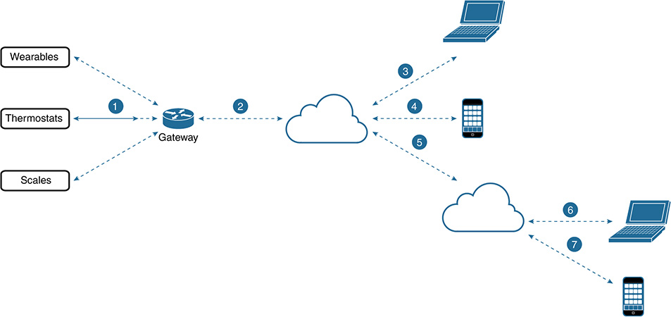
Consider the Fitbit Aria, a connected scale within a home. This device connects to the home network and pushes data to the Fitbit cloud. The following steps show how the data can be displayed via native applications and web browsers, and how third-party services can leverage that data:
The Fitbit Aria connects to the Wi-Fi router (1). This solution syncs stats wirelessly with an online graph and mobile tool.
On the home network, the user’s weight and body fat data are pushed to the Fitbit cloud (2). The Fitbit servers recognize that the data has come from the user Bob because the scale was associated with Bob’s user account as part of the installation process.
When the data is in the Fitbit cloud, it can be displayed via a web browser (3) and also via native applications (4).
Third-party services, such as TrendWeight (5) and Tictrac (6), offer additional web applications (7) that give the user access to their weight data and related visuals.
Cloud to Cloud
At the user’s request, TrendWeight can use OAuth 2.0 to obtain an access token from Fitbit representing that particular user. This is important because the user is involved in the process of TrendWeight obtaining the access token. Fitbit has the option to provide a “consenting interface” that allows the user to specify granular permissions. For example, TrendWeight might see a user’s weight loss but not weight gain, or might see Dataset A on the weekdays but not the weekends.
TrendWeight attaches the token to its subsequent calls to the Fitbit API for that user. When Fitbit receives the API call from TrendWeight, it extracts the token and takes the following actions:
Determines which user the token was applied to
Checks that the actions TrendWeight is requesting are consistent with the permissions the user previously attached to that token
Ensures that the token falls within the valid time frame
Figure 9-68 shows the flow among the user, TrendWeight, and Fitbit.

Instead of requiring a particular user to mediate the token issuance (to ensure privacy), TrendWeight can directly ask Fitbit for a token. Figure 9-68 illustrates OAuth providing an access token to TrendWeight that can be used to access a given user’s weight data. Now, if TrendWeight also desired additional identity attributes for the user (personal profile) or wanted to support a “sign on with the Fitbit account” SSO model, OpenID Connect features would become relevant.
In addition to an access token used on API calls to Fitbit (as OAuth enables), TrendWeight would receive what OpenID Connect refers to as an identity token, a standardized and secured container for additional identity attributes of the user (such as when the user last authenticated to Fitbit).
This flow presumes that the user is authenticated to Fitbit for the purpose of assigning permissions to TrendWeight. This is a sensitive security step, so ideally, it should happen only after the user is properly authenticated to Fitbit.
Native Applications to the Cloud
In many models, the native application is associated with a particular device (or possibly a family of devices from the same provider). After it is downloaded from the public app store and installed, the native application must be registered and bound to a particular user account.
In OAuth and Connect, the registration process consists of the native application being issued a set of tokens that represent the given user. The native application attaches these tokens to API calls to the corresponding cloud endpoints. Using Figure 9-67 as an example, the Fitbit native application calls a Fitbit API to retrieve a particular user’s weight data so that it can be analyzed for historical depiction in the browser (step 4).
The registration process requires the user to authenticate to the appropriate cloud. Best practice dictates that this step should happen in a browser window, either the default mobile browser or one embedded into the UI of the native application itself. After authenticating in the browser, the user can be given a consent page to determine what permissions to give to the native application. Figure 9-69 illustrates the Fitbit native application registering itself.
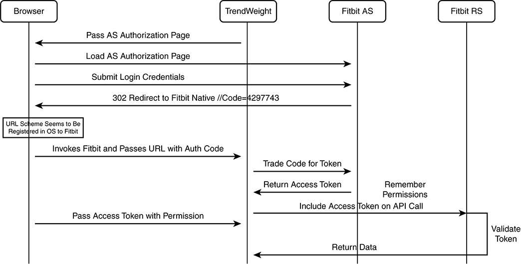
The Fitbit AS issues the access token and remembers the corresponding user, along with what permissions are attached to it. The Fitbit native application stores this token in the mobile OS secure storage so that it can be included on all subsequent API calls. The Fitbit OAuth and API infrastructure can treat this native application API client almost identically to third-party server clients such as TrendWeight.
A home most likely has multiple devices and the homeowners also likely have installed the corresponding native applications on their mobiles. After creating accounts at each provider, the homeowners authenticate from the native application, which links the native application to their identity at that provider. As discussed previously, OAuth provides a standardized mechanism for this step.
Regardless of whether the calls from the native applications to their corresponding cloud servers are protected by OAuth or some proprietary security framework, the two stacks are effectively in silos. Some control occurs between home automation hubs and individual devices, but there is no identity interoperability. In other words, no option exists to use an identity at one provider in order to use the services of another.
The federated features of OpenID Connect would support a model in which the homeowner could use an existing identity at the smart home provider instead of creating another account. Homeowners could even avoid installing another app onto their phone, presuming some sort of interoperability between the smart home native application and the device API.
Device to Device
As we have discussed several times in this chapter, many devices and applications might not use HTTP, but might instead use a messaging protocol that is optimized for the constraints of devices (such as XMPP, MQTT, and CoAP). Some early explorations considered binding OAuth to IoT-optimized protocols. As an example, a whitepaper by HiveHQ illustrates how to connect to an MQTT broker with an access token and, ultimately, how to use OAuth for the authentication of MQTT calls. If a token could be retrieved, that token could be leveraged in the Connect message using the password field. We looked at the MQTT Connect message architecture earlier in this chapter.
Connect relies on the JavaScript Object Signing and Encryption (JOSE) suite of specifications to protect its JSON tokens. However, text-based JSON might not be appropriate for constrained devices. Constrained Object Signing and Encryption (COSE) is a proposal for standardizing security mechanisms that are similar to JOSE for such devices. Even if OAuth and Connect are not directly bound to the device-to-device interactions in the proximal network, the concept of permission-based security token issuance to clients will likely be relevant.
As an example, when instantiating a new device onto a home network, the homeowner would be granted the opportunity to assign that new device permissions related to its operations and interactions with other devices. These permissions would be issued through tokens that the new device uses on subsequent MQTT or equivalent calls. This method is quite innovative, but more work needs to be done on the front end (for example, getting a token onto a constrained endpoint).
In a conference research paper titled “Federated Identity and Access Management for the Internet of Things,” Paul Fremantle examines specific challenges of sensors and actuators. Fremantle built a prototype that uses OAuth2 to enable access control to information distributed via MQTT. This prototype consists of four major components: the MQTT broker, the authorization server (AS), a Web Authorization Tool (WAT), and the device (Arduino). Figure 9-70 illustrates this setup.
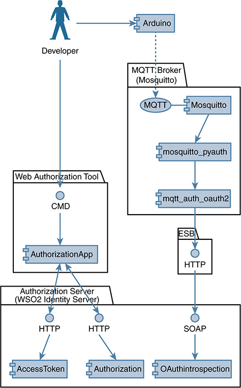
To instantiate the bearer and refresh tokens and associate the appropriate access control scopes, Fremantle created a WAT, a Python command-line tool that spawned a browser with the URL to request a token. The tool generated a textual version of the token that generates C code for the Arduino that can be cut and pasted. In real-world deployments, the capability to write this directly into the flash on a device would be useful.
A token-based framework undoubtedly helps with scalability, but the need for standardization, particularly on constrained devices, is evident. Considerations include token size, where to place the token, and how constrained devices can obtain and refresh tokens using common IoT protocols. All of these must evolve to merit better adoption.
The high demand IoT use cases are placing on identity and security mechanisms requires us to rethink how to give users meaningful control over how personal data is shared. IoT demands an interoperable, standardized identity layer. To satisfy these requirements, OAuth and OpenID Connect have shown promise in scaling the permissions landscape for IoT use cases.
Evolving Concepts: Need for Identity Relationship Management
Current IAM vendors and solutions are familiar with enterprise scenarios involving large numbers of both people and associated attributes. As an example, an IAM provider might have one authoritative source for the employee and 20 to 30 attributes. The IAM provider can leverage that information to differentiate access and manage user lifecycles, and it has been optimized for those scenarios.
According to the Cisco visual networking index (VNI) report, one common scenario looks at the managed device count per IT person for both financial and retail customers (see Figure 9-71).
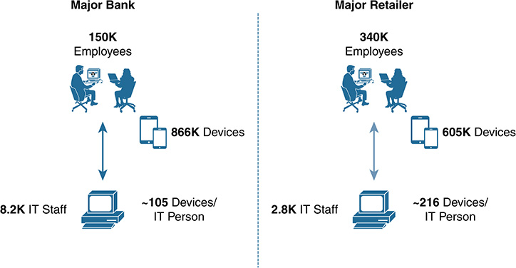
In Figure 9-71, the bank customer on the left has fewer overall employees but more devices per employee; hence it has a larger IT staff. The count of managed devices per IT person is around 105 for this customer. The retailer has a much higher employee count but has only 1.7 devices per employee; hence, it has a smaller IT staff to manage them. The retailer’s managed device count per IT person is around 216. These are fairly common numbers today.
If the bank attempts to leverage the IoT as originally intended and connects all its parking spots, lights, vending machines, and so on, that would add another 5 million devices. Now imagine the number of IT personnel the bank would need if it wanted to retain the same ratio of managed devices per employee (see Figure 9-72). Of course, the scale might not be exactly linear, but the strategy would still need to be rethought.

Figure 9-72 Managed Device Count per IT Person for Financial and Retail Customer After Adding IoT Devices
As you can see from Figure 9-72, the current IAM capabilities needed to scale might have to evolve. The world is becoming dominated by an exponential connection rate that we have never seen. From smartphones to connected cars, connected homes, and industrial sensors, the number of actors and the connections between them is growing exponentially.
Unfortunately, that growth has not been met with adequate innovation to successfully address the issue. The current policies, technologies, and processes that govern identity management require evolution. Figure 9-73 shows the complex matrix of relationships (from the Kantara Initiative Report).

As we bind people to devices, devices to devices, devices to clouds, clouds to clouds, and so on, we end up with a much larger number of relationships, each with sets of attributes. This evolved matrix of relationships makes identity the new perimeter. IRM is a new way of considering digital identity, and it potentially includes concepts to scale to the numbers required.
IRM began as a movement by a group of industry experts to transform classical IAM to meet the next-generation demand of digital identity. It operates under the banner of the Kantara Initiative.
The Kantara Initiative produced a report titled “The Design Principles of Relationship Management,” which specifies the meaning and function of relationships as a component of digital identity services. The report highlights what relationships need to represent and how they need to behave to maintain the integrity, coherence, and utility of identity services at Internet scale. The initial goal of the report was to serve as a conversational substrate to capture evolving concepts around IAM. The report represents an entry into high-level strategic, policy, and technology review and research on the implications of relationships and their design principles, types, and axioms. The report is not conclusive; instead, it attempts to provide a substrate for further industry development. The Kantara Initiative walks through a set of design principles that discuss person-to-person interactions and relationships. However, these design principles are just as applicable to things. Different implications might arise with respect to relationship type (for example, person-to-person, thing-to-thing, or person-to-thing).
The following lists the design principles. Each design principle is listed but only a summary explanation is provided. Refer to the actual Kantara Initiative report for a more comprehensive explanation.
■ Scalable: The number of relationships IAM systems need to design for and manage will increase at an exponential rate. Scalability must cover the following:
■ Actors
■ Attributes
■ Relationships
■ Administration
■ Actionable: We want relationships that can do something of value—and, more specifically, relationships that can carry authorization data. However, relationships are not required to carry authorization data; to scale, they must do so. The traditional model of communicating with a request-response to a back-end system does not scale, so this work must be done on the front end.
■ Immutable: Immutable relationships do not change and thus can provide a baseline for IAM. An example could be, “This thing was made by Emerson.” Note that only some relationships are immutable; most are not and should not be.
■ Transferable: In a transferable relationship, when one party can be substituted for another.
■ Contextual: Some relationships can be invoked by changes in context. Changes to conditions external to the relationship might impact both how the actor behaves and what/how the external party observes.
■ Provable: The capability to prove the existence and nature of relationships improves trust between parties; provides auditability, accountability, and traceability; and potentially reduces asymmetries of power.
■ Acknowledgeable: Participants can acknowledge that they have relationships with other actors. In this regard, the acknowledgeable characteristic of relationships feels very similar to single-party asserted relationships.
■ Revocable: IAM professionals understand revocation in terms of credential management. Common practices surrounding data generated by relationships are less commonly understood. This concept of revocability is also related to developing legal approaches such as the right to be forgotten. This involves the combination of asymmetry and the capability (or lack of capability) for a data subject to remove personally identifiable data.
■ Constrainable: All behaviors and allowable actions associated with a relationship must be able to be constrained based on the desires, preferences, and even business models of the parties involved. In some cases, the constraints applied to a relationship might look like consent.
Summary
This chapter began with a primer on prenetwork access, to provide an elementary discussion of device provisioning in terms of establishing a trusted identity on a device via bootstrapping, creating a unique naming taxonomy, and registering a device to be used on the network. We then moved into the chapter’s focus area, exploring methods to identify devices as they attempt to gain access to the network, methods to authenticate those devices, and automated solutions that provide the appropriate access privileges based on identity. We illustrated the importance of the last A in the AAA concept (accounting), which is essential for troubleshooting purposes, audits, and higher-level billing purposes. We then transitioned into how federation concepts and technologies such as OAuth and OpenID Connect can offer additional options to scale identity and authorization. Finally, we discussed the rapidly evolving matrix of relationships and looked at reasons to consider moving to IRM as a new method of scaling. The next chapter discusses methods of threat detection and how to automate and orchestrate threat detection capabilities throughout the network diameter.
References
Amazon Web Services, “What Is IAM?”, https://docs.aws.amazon.com/IAM/latest/UserGuide/introduction.html
The Bio-T: The Biometric Internet of Things, http://www.techzone360.com/topics/techzone/articles/2016/11/11/427053-bio-t-biometric-internet-things.htm
Bootstrapping Remote Secure Key Infrastructure, https://tools.ietf.org/html/draft-ietf-anima-bootstrapping-keyinfra-07
Certificate Revocation (CRL vs. OCSP), https://www.fir3net.com/Security/Concepts-and-Terminology/certificate-revocation.html
Cisco Trust Anchor Technologies, https://www.cisco.com/c/dam/en_us/about/doing_business/trust-center/docs/trust-anchor-technologies-ds-45-734230.pdf
Cisco Unified Access (UA) and Bring Your Own Device (BYOD) CVD, https://www.cisco.com/c/en/us/td/docs/solutions/Enterprise/Borderless_Networks/Unified_Access/BYOD_Design_Guide/BYOD_ISE.html
Configuring Certificate Revocation, https://technet.microsoft.com/en-us/library/cc771079(v=ws.11).aspx
Configuring IEEE 802.1X Port Based Authentication, https://www.cisco.com/c/en/us/td/docs/switches/lan/catalyst3750x_3560x/software/release/12-2_55_se/configuration/guide/3750xscg/sw8021x.html
The Constrained Application Protocol (CoAP), https://tools.ietf.org/html/rfc7252
Cyber Threat Defense 2.0 Design Guide, https://www.cisco.com/c/dam/en/us/td/docs/security/network_security/ctd/ctd2-0/design_guides/ctd_2-0_cvd_guide_jul15.pdf
Federated Identity and Access Management for the Internet of Things, https://www.researchgate.net/publication/264347555_Federated_Identity_and_Access_Management_for_the_Internet_of_Things
Kantara Initiative, https://kantarainitiative.org/
Manufacturer Usage Description Specification, https://tools.ietf.org/html/draft-ietf-opsawg-mud-13
MQTT Essentials Part 3: Client, Broker, and Connection Establishment, https://www.hivemq.com/blog/mqtt-essentials-part-3-client-broker-connection-establishment
MQTT Security Fundamentals, https://www.hivemq.com/blog/mqtt-security-fundamentals-tls-ssl
OAUTH2.0: Why It’s Vital to IoT Security, https://nordicapis.com/why-oauth-2-0-is-vital-to-iot-security
Payment Card Industry (PCI) Data Security Standard, Requirements and Security Assessment Procedures 3.2, https://pcicompliance.stanford.edu/sites/default/files/pci_dss_v3-2.pdf
RADIUS Change of Authorization by Cisco Systems, https://www.cisco.com/c/en/us/td/docs/ios-xml/ios/sec_usr_aaa/configuration/xe-3s/sec-usr-aaa-xe-3s-book/sec-rad-coa.pdf
RFC 7228, Terminology for Constrained-Node Networks, https://tools.ietf.org/html/rfc7228
Standardized Identity Protocols and the Internet of Things, https://www.pingidentity.com/en/resources/client-library/white-papers/2015/standardized-identity-protocols-and-the-internet-of-things.html
Terminology for Constrained Node Networks, https://tools.ietf.org/html/rfc7228
What Is an X.509 Certificate?, https://access.redhat.com/documentation/en-US/Fuse_MQ_Enterprise/7.1/html/Security_Guide/files/X509CertsWhat.html