
Design of Upper Limb Exoskeletons
A.1 Heavy duty exoskeleton robot
We use the PowerCube motors as the basic elements for the joints of the exoskeleton. All joint modules are integrated using the universal communication interfaces CAN. Each joint has its own computer control system. The joint modules are fitted with a standardized interface for mechanism and control. The 4-DoF upper limb exoskeleton is mounted on the ground. This allows both height and distance adjustment between the arms; see Fig. A.1. Articulation of the exoskeleton is four single axes: three for the shoulder and one for the elbow. We also develop an admittance control for this 4-DoF upper limb exoskeleton. It uses the force interactions between the device and the user to create trajectories directly.

The advantage of modular design for the robot exoskeleton is that the design process is more simple and easier than the other exoskeletons. The design of the upper limb exoskeleton is based on the kinematics and dynamics of the human arm during activities of daily living. The human upper limb is composed of segments linked by articulations with multiple degrees of freedom. It is a complex structure that is made up of both ridged bone and soft tissue. This soft tissue moves and slides relative to the bone during movements and interactions with the environment. Additionally, muscle contractions cause changes to their shape and the overall stiffness of the arm. Although much of the complexity of the soft tissue is difficult to model, the overall arm movement can be represented by a much simpler model composed of ridge links connected by joints.
Three ridged segments, consisting of the upper arm, lower arm, and hand connected by frictionless joints make up the simplified model of the human arm. Placing a reference frame at the shoulder, the upper arm, and torso are rigidly attached by a ball and socket joint. This joint is responsible for three shoulder motions: abduction–adduction, flexion–extension, and internal–external rotations. The connection between the upper and lower arm segments can be regarded as a single rotational joint at the elbow. We do not consider the wrist motion. So the human arm has a 4-DoF, which represents four basic motions of the human arm as in Fig. A.2. The range of motion of the arm is shown in Table A.1.
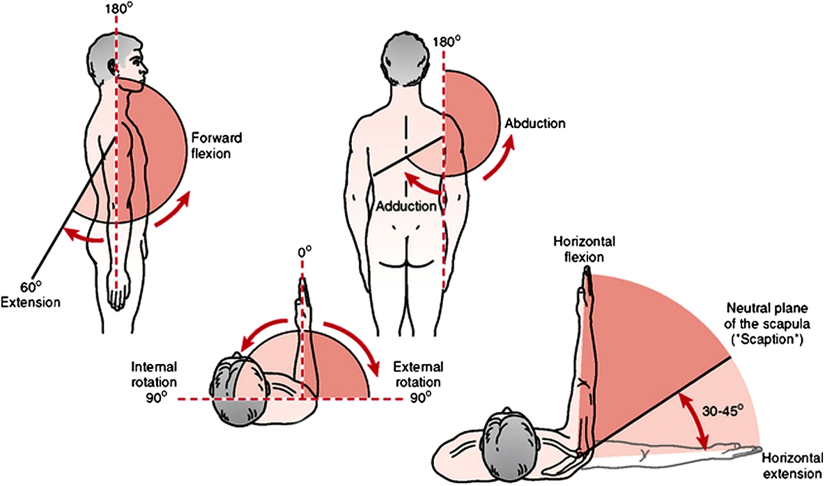
Table A.1
Human arm performance
| abduction adduction | flexion extension | internal external | elbow | |
|---|---|---|---|---|
| Range of motion | 0–180 | −45–180 | −60–100 | 0–150 |
| Daily living | 0–80 | −20–30 | −30–40 | 20–80 |

The fundamental principle in designing the exoskeleton joints is to align the rotational axis of the exoskeleton with the anatomical rotations axes. If more than one axis is at a particular anatomical joint, for example, the spherical joint of the shoulder or wrist, the three axes must be intersected, and the elbow axis is orthogonal to the third shoulder axis. The pronation–supination takes place between the elbow and the wrist as it does in the physiological mechanism. The simplification of this paper supports 99% of the ranges of motion required to perform daily activities [110].
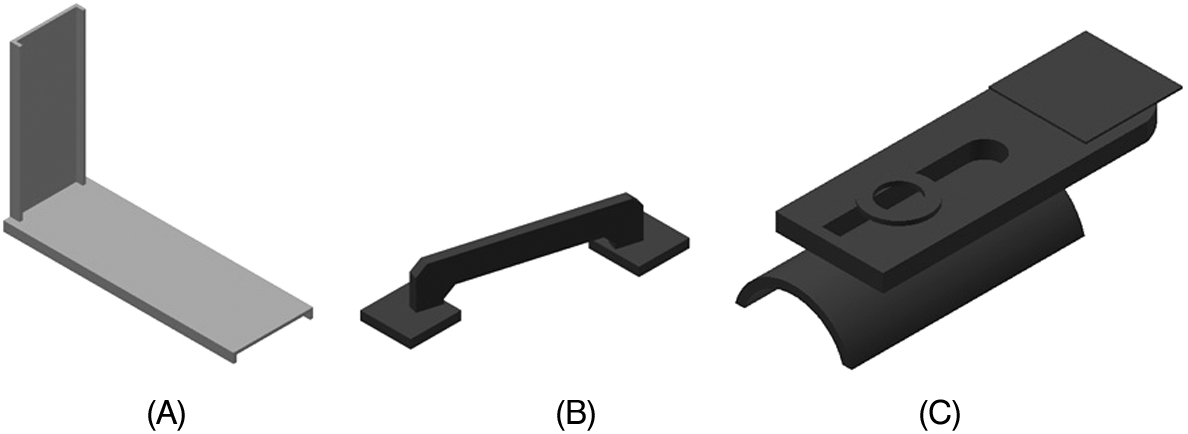
The joint configuration and DoF selection are shown in Fig. A.3. This configuration satisfies two basic requirements: 1) all of their rotation axes are orthogonal (ball joint), and 2) the three rotation axes are intersected in one point. In order to simulate the motions of abduction–adduction, flexion–extension, and internal–external rotations, the special link pieces are designed as in Fig. A.4. These three links satisfy the basic requirements of the human upper limb.

The links L0 and L4 are adjustable. L0 is for different height of persons, L4 is different length of human arms. The exoskeleton's height is adjusted for each user in a seated position; see Fig. A.1. The user's left hand is an enable button, which released the brakes on the device and engaged the motor.
Table A.2 gives the physics parameters of the four links. The thickness of all links are 4.76 mm.
Table A.2
| Link | Mass (g) | Dimension (mm) |
|---|---|---|
| 1 | 2875 | long: 345, width: 228, high: 100 |
| 2 | 1578 | long: 190, width: 175, high: 100 |
| 3 | 1576 | long1: 345, width1: 228, long2: 220, width2: 95 |
| 4 | 2115 | long1: 220, width1: 95, long2: 220, width2: 72 |
The safety steps includes the mechanical, electrical, and software designs. In the mechanical part, it has a physical stop to prevent segments in the joints. The electrical part is added as an emergency shutoff button to terminate motor motion. The most easy method is to use software to monitor the power transmission integrity to limit motor currents, i.e., motor torques. When the motor moves near to the limits, a brake command is sent to this motor, via software in selected maxim and minimum range of degree for the movements for each one.
The concept of the exoskeleton design in this paper is that we divided the exoskeleton into: joint (actuation), link, and control system. Each subsystem has its own function and can be independently tested. This design allows us to increase or reduce DoF directly, for example, from the 4-DoF exoskeleton of this paper to the 7-DoF exoskeleton [110]. The advantages of this design are saving time, reduction in cost, and flexibility in design.
The rotational DoF is actuated by the PowerCube unit. The cubic geometry makes the system extremely adaptable for modular solutions. The benefit of this unit for our modular design is it can be mounted on four sides; see Fig. A.5. This overcomes the frequent changes of customer demands, and makes the manufacturing process more adaptive to the change. The PowerCube unit has a brushless EC motor. The transmission of this unit is a harmonic drive.

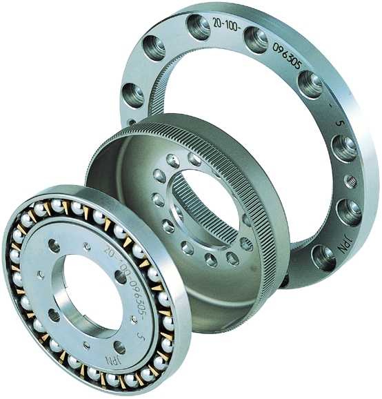
The structure of a harmonic drive is shown in Fig. A.6. There are three components of the transmission that rotate at different speeds and in the same axis of rotation. They are the flex spline, wave generator, and circular spline. The external teeth of the flex spline mesh with the internal teeth of the circular spline along the major axis of the ellipse of the wave generator. The mechanism of the harmonic drive is that the wave generator has the engagement area on its axis when this area is moved ![]() around the circumference of the circular spline and the flex spline. By this continuous engagement of the gear teeth, each rotation of the wave generator with the flex spline and the circular spline has drive transmission in the range of
around the circumference of the circular spline and the flex spline. By this continuous engagement of the gear teeth, each rotation of the wave generator with the flex spline and the circular spline has drive transmission in the range of ![]() to
to ![]() . The mechanism efficiencies are around
. The mechanism efficiencies are around ![]() . The main advantage of the harmonic drive is the small space transmission provides bigger torque output than the other gear boxes.
. The main advantage of the harmonic drive is the small space transmission provides bigger torque output than the other gear boxes.
The harmonic drive has three types of motions by combinations of the three components: high speed rotation, low speed rotation, and high torque rotation. The PowerCube unit uses the high torque rotation, where the flex spline is fixed and the wave generator is transmitted through the circular spline. So the servo positioning module combines high precision and high torque, and has a very compact design. The high torques are achieved by the integrated harmonic drive gears with considerable reserves of acceleration and deceleration, while the high-resolution encoder guarantees high precision.
If the transmission ratio of the harmonic drive is defined as N, the ideal rotation of the third component is
where ![]() ,
, ![]() , and
, and ![]() are the rotations of the wave generator, the circular spline, and the flex spline. If
are the rotations of the wave generator, the circular spline, and the flex spline. If ![]() , the wave generator rotates N times faster than the flex spline in the opposite direction. A fixed flex spline wave generator causes the rote
, the wave generator rotates N times faster than the flex spline in the opposite direction. A fixed flex spline wave generator causes the rote ![]() times faster than the circular spline in the same direction.
times faster than the circular spline in the same direction.
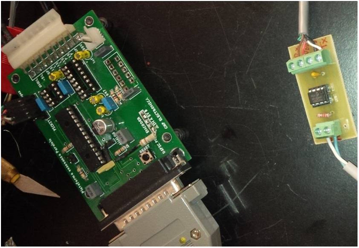
All of actuation modules are connected by the CAN bus (Controller Area Network), which uses single-cable technology to integrate the existing modules; see Fig. A.7. CAN allows microcontrollers and devices to communicate with each other without a host computer. The module can have a single CAN interface rather than an analog and digital inputs to every device in the system. This decreases overall cost and the weight of each joint. The new module can quickly be integrated into existing systems using the universal communication that interfaces CAN.
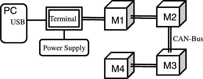
CAN communicates with a PC with a DSPIC30F4012 card or USB port. It is a message-oriented protocol. Each message has a unique identifier within the network, in which nodes choose to accept or reject the message. Protocol of CAN includes three layers: physical layer, data link layer, and special coating for management (control node layer).
CAN solves the simultaneous transmission problem by assigning priorities by the identifier of each message. The identifier with the lowest binary number is the highest priority. The medium access methods used in CAN are the Carrier Sense Multiple Access (CSMA), Collision Detection (CD), and Arbitration on Message Priority (AMP). If a node in the network needs to transmit information, it must wait until the bus is free. When this condition is met, this node transmits four types of frames: remote frame, error frame, extended frame, and overload frame.
Another part of the control system is the human machine interface (HMI), which receive a human command and send the corresponding trajectories to the actuators. The HMI of this exoskeleton consists of three attachment points on the exoskeleton. One attachment point is for the upper arm, one is for the lower arm, and the last is for the hand. The communication interface is USB with the CAN bus with DsPic; see Fig. A.8.
A.2 Portable exoskeleton robot
The human shoulder is capable of three basic movements showed in Fig. A.9, which are abduction, flexion–extension, and rotation. A fourth movement is the circle, which can be considered as the combination of abduction and flexion–extension. Because the rotation is an orientation movement of the elbow, in this paper it will not be considered. The design goals of the portable exoskeleton robot are:
- • The exoskeleton should be able to perform the movements of flexion–extension and abduction freely, avoiding the singularity caused by the configuration of the link.
- • It has the ability to operate in passive or active mode. In the passive mode the user is able to move the exoskeleton with their own strength. In the active mode the exoskeleton is able to move the user's shoulder.
- • The structure should be lightweight and compact to be installed, and is fixed with the human body.

As the exoskeleton should be light and rigid enough to withstand the forces operating in the structure, it is made completely of aluminum. The actuators are selected as the Dynamixel's motors, model MX-64T, because they have good characteristics in their control torques, mechanical strength, operating voltage, and reduced dimensions.
In this design, we only use two motors to complete the pitch and yaw torques at the same time. The yaw direction uses the spherical mechanisms; see Fig. A.10.
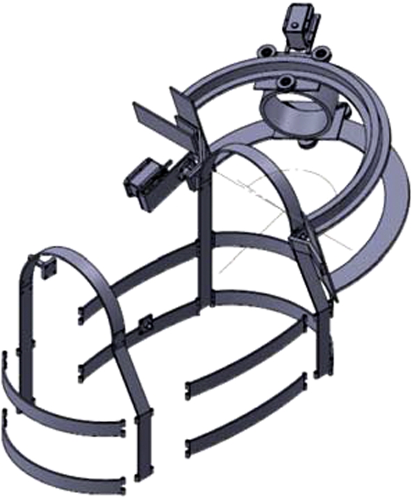
To achieve the three basic movements of human shoulder the structure design is based on the 2-DoF polar robot. The work area is similar to the ball joint. The two revolute joints have 90-degree displacements, and the intersect axes are in the origin.
The joint ![]() has simple configuration with axle torque transmission. The joint
has simple configuration with axle torque transmission. The joint ![]() does not have the axle transmission, but it needs rotation axis. So we use the pinion mechanism and a circular rack, which is centered on rotation axis. This system allows the joints to move freely without big force of the human arms. This exoskeleton allows natural movement (passive mode) and active movement; see Fig. A.11.
does not have the axle transmission, but it needs rotation axis. So we use the pinion mechanism and a circular rack, which is centered on rotation axis. This system allows the joints to move freely without big force of the human arms. This exoskeleton allows natural movement (passive mode) and active movement; see Fig. A.11.

The servomotors have microcontrollers inside. The control structure is the serial communication protocol synchronic half duplex, which uses the UART-USB interface and a computer. The servomotors send their information, such as temperature, voltage, and angular position to the computer. The control software in the PC runs is a Pentium Core2Duo with 2GB of RAM and a 120GB hard drive. The operating system is the Linux Mint 15 “Olivia.” We use it because the development software has the GNU General Public License. The development environment is Qt4 with C++, which allows better performance at runtime without MATLAB-Simulink®. Another advantage is that it can generate executable programs, which can be easily applied in the other computers.