Well Components
Abstract
The role of a production engineer is to maximize oil and gas production in a cost-effective manner. Familiarization and understanding of oil and gas production systems are essential to the engineers. This chapter provides petroleum engineering students and production engineers with some basic knowledge about production systems. A complete oil or gas production system consists of a reservoir, well, flowline, separators, pumps, transportation pipelines, and safety control systems. The reservoir supplies the wellbore with crude oil or gas. The wellbore provides a path for the production fluid to flow from bottom hole to surface and offers a means to control the fluid production rate. The flowline leads the produced fluid to separators. The separators remove gas and water from the crude oil. Pumps and compressors are used to transport oil and gas through pipelines to sales points. Through the one and half century of pipeline operating practice, the petroleum industry has proven that pipelines are by far the most economical means of large-scale overland transportation for crude oil, natural gas, and their products, clearly superior to rail and truck transportation over competing routes, given large quantities to be moved on a regular basis. The purpose of safety systems is to protect personnel, the environment, and the facility. The major objective of the safety system is to prevent the release of hydrocarbons from the process and to minimize the adverse effects of such releases if they occur.
Keywords
Reservoirs; wells; facilities; pipelines; safety
1.1 Introduction
Role of a production engineer is to maximize oil and gas production in a cost-effective manner. Familiarization and understanding of oil and gas wells are essential to the engineers. This chapter provides graduating production engineers with some basic knowledge about petroleum production wells. More engineering principles are discussed in the later chapters.
Wells fall into categories of oil, condensate, and gas wells depending on the producing gas–oil ratio (GOR). Gas wells are wells with producing GOR being greater than 100,000 scf/stb; condensate wells are those with producing GOR being less than 100,000 scf/stb but greater than 5000 scf/stb; and wells with producing GOR being less than 5000 scf/stb are classified as oil wells.
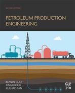
Fig. 1.1 shows a simple oil production system where a well provides a link between an oil reservoir and surface facilities. The well consists of a wellbore, a wellhead, and a flowline leading the produced fluids to separators.
1.2 Wellbore
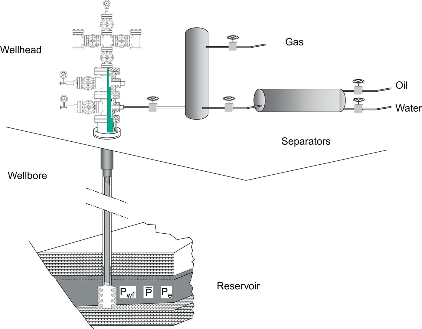
Fig. 1.2 shows a typical flowing oil well, defined as a well producing solely because of the natural pressure of the reservoir. It is composed of casings, tubing, packers, down-hole chokes (optional), wellhead, Christmas tree, and surface chokes.
Oil and gas wellbores are constructed like an upside-down telescope. The large-diameter borehole section is at the top of the well. Each section is cased to the surface, or a liner is placed in the well that laps over the last casing in the well. Each casing or liner is cemented into the well (usually up to at least where the cement overlaps the previous cement job).
The last casing in the well is the production casing (or production liner). Once the production casing has been cemented into the well, the production tubing is run into the well. Usually a packer is used near the bottom of the tubing to isolate the annulus between the outside of the tubing and the inside of the casing. Thus, the produced fluids are forced to move out of the perforation into the bottom of the well and then into the inside of the tubing. Packers can be actuated by either mechanical or hydraulic mechanisms. The production tubing is often (particularly during initial well flow) provided with a bottom-hole choke to control the initial well flow (i.e., to restrict overproduction and loss of reservoir pressure).
Most wells produce oil through tubing strings, mainly because a tubing string provides good sealing performance and allows the use of gas expansion to lift oil. The American Petroleum Institute (API) defines tubing size using nominal diameter and weight (API, 1987a). The nominal diameter is based on the internal diameter of the tubing body. The weight of tubing determines the tubing outer diameter. Steel grades of tubing are designated H-40, J-55, C-75, L-80, N-80, C-90, and P-105, where the digits represent the minimum yield strength in 1000 psi. The minimum performance properties of tubing are given in Chapter 9 and Appendix B.
1.3 Wellhead
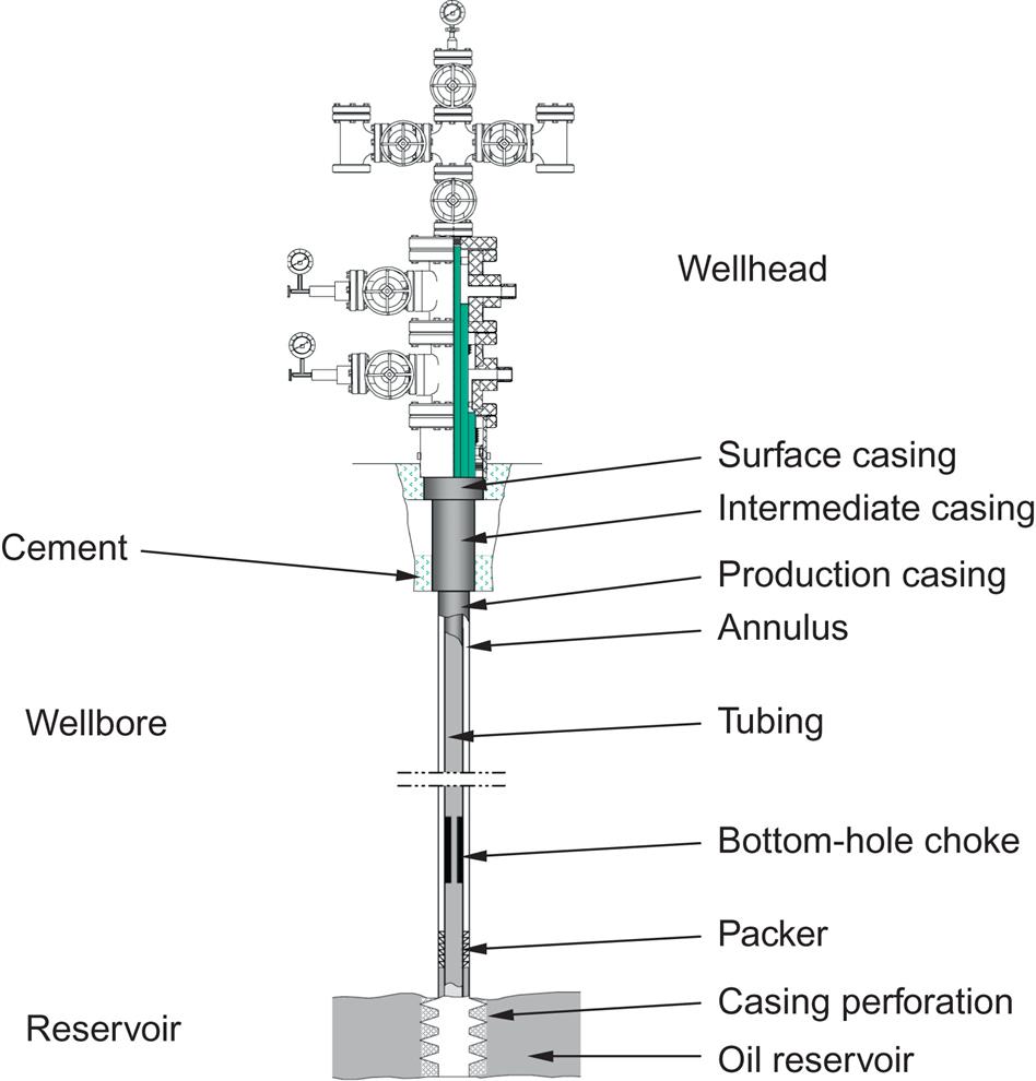
The “wellhead” is defined as the surface equipment set below the master valve. As we can see in Fig. 1.3, it includes casing heads and a tubing head. The casing head (lowermost) is threaded onto the surface casing. This can also be a flanged or studded connection. A “casing head” is a mechanical assembly used for hanging a casing string (Fig. 1.4). Depending on casing programs in well drilling, several casing heads can be installed during well construction. The casing head has a bowl that supports the casing hanger. This casing hanger is threaded onto the top of the production casing (or uses friction grips to hold the casing). As in the case of the production tubing, the production casing is landed in tension so that the casing hanger actually supports the production casing (down to the freeze point). In a similar manner, the intermediate casing(s) are supported by their respective casing hangers (and bowls). All of these casing head arrangements are supported by the surface casing, which is in compression and cemented to the surface. A well completed with three casing strings has two casing heads. The uppermost casing head supports the production casing. The lowermost casing head sits on the surface casing (threaded to the top of the surface casing).

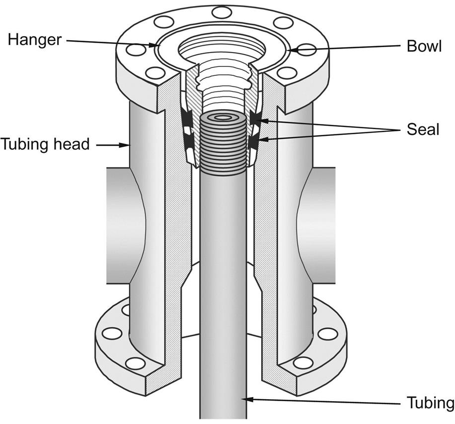
Most flowing wells are produced through a string of tubing run inside the production casing string. At the surface, the tubing is supported by the tubing head (i.e., the tubing head is used for hanging tubing string on the production casing head (Fig. 1.5)). The tubing head supports the tubing string at the surface (this tubing is landed on the tubing head so that it is in tension all the way down to the packer).
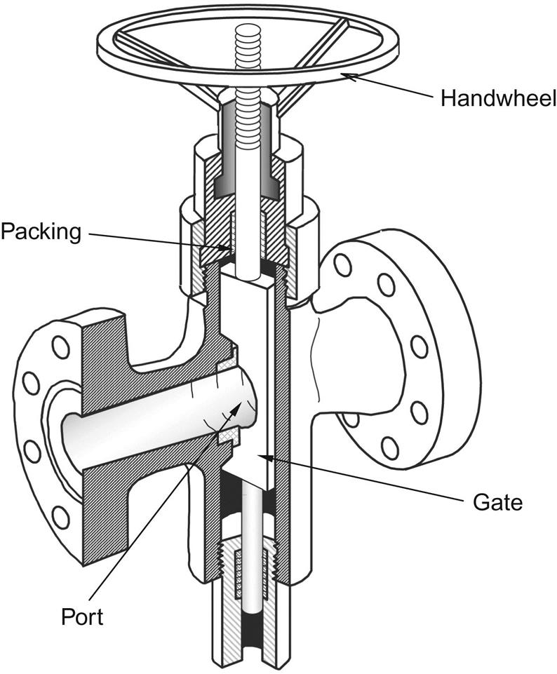
The equipment at the top of the producing wellhead is called a “Christmas tree” (Fig. 1.6) and it is used to control flow. The Christmas tree is installed above the tubing head. An “adaptor” is a piece of equipment used to join the two. The Christmas tree may have one flow outlet (a tee) or two flow outlets (a cross). The master valve is installed below the tee or cross. To replace a master valve, the tubing must be plugged. A Christmas tree consists of a main valve, wing valves, and a needle valve. These valves are used for closing the well when needed. At the top of the tee structure (on the top of the Christmas tree), there is a pressure gauge that indicates the pressure in the tubing. The wing valves and their gauges allow access (for pressure measurements and gas or liquid flow) to the annulus spaces (Fig. 1.7).

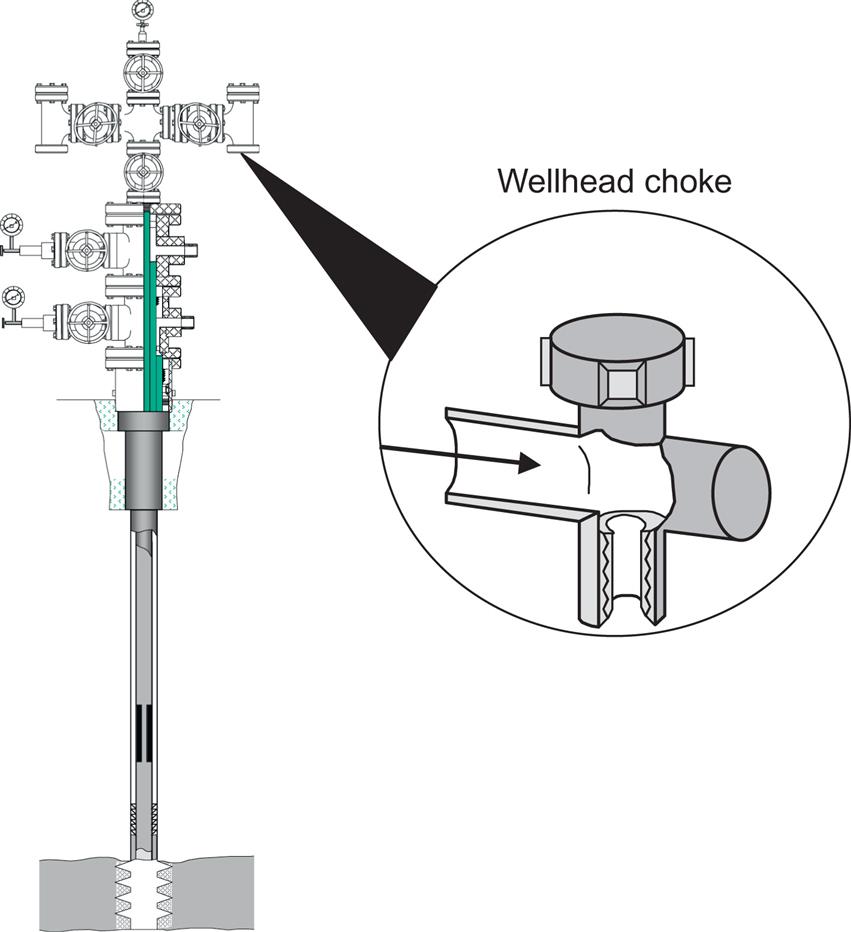
“Surface choke” is a piece of equipment used to control the flow rate (Fig. 1.8). In most flowing wells, the oil production rate is altered by adjusting the choke size. The choke causes back-pressure in the line. The back-pressure (caused by the chokes or other restrictions in the flowline) increases the bottom-hole flowing pressure. Increasing the bottom-hole flowing pressure decreases the pressure drop from the reservoir to the wellbore (pressure drawdown). Thus, increasing the back-pressure in the wellbore decreases the flow rate from the reservoir. In some wells, chokes are installed in the lower section of tubing strings. This choke arrangement reduces wellhead pressure and enhances oil production rate as a result of gas expansion in the tubing string. For gas wells, use of down-hole chokes minimizes the gas hydrate problem in the well stream. A major disadvantage of using down-hole chokes is that replacing a choke is costly.
Certain procedures must be followed to open or close a well. Before opening, check all the surface equipment such as safety valves, fittings, and so on. The burner of a line heater must be lit before the well is opened. This is necessary because the pressure drop across a choke cools the fluid and may cause gas hydrates or paraffin to deposit out. A gas burner keeps the involved fluid (usually water) hot. Fluid from the well is carried through a coil of piping. The choke is installed in the heater. Well fluid is heated both before and after it flows through the choke. The upstream heating helps melt any solids that may be present in the producing fluid. The downstream heating prevents hydrates and paraffins from forming at the choke (Guo and Ghalambor, 2012).
Surface vessels should be open and clear before the well is allowed to flow. All valves that are in the master valve and other downstream valves are closed. Then follow the following procedure to open a well:
1. The operator barely opens the master valve (just a crack), and escaping fluid makes a hissing sound. When the fluid no longer hisses through the valve, the pressure has been equalized, and then the master valve is opened wide.
2. If there are no oil leaks, the operator cracks the next downstream valve that is closed. Usually, this will be either the second (backup) master valve or a wing valve. Again, when the hissing sound stops, the valve is opened wide.
3. The operator opens the other downstream valves the same way.
4. To read the tubing pressure gauge, the operator must open the needle valve at the top of the Christmas tree. After reading and recording the pressure, the operator may close the valve again to protect the gauge.
The procedure for “shutting-in” a well is the opposite of the procedure for opening a well. In shutting-in the well, the master valve is closed last. Valves are closed rather rapidly to avoid wearing of the valve (to prevent erosion). At least two valves must be closed.
1.4 Flowline
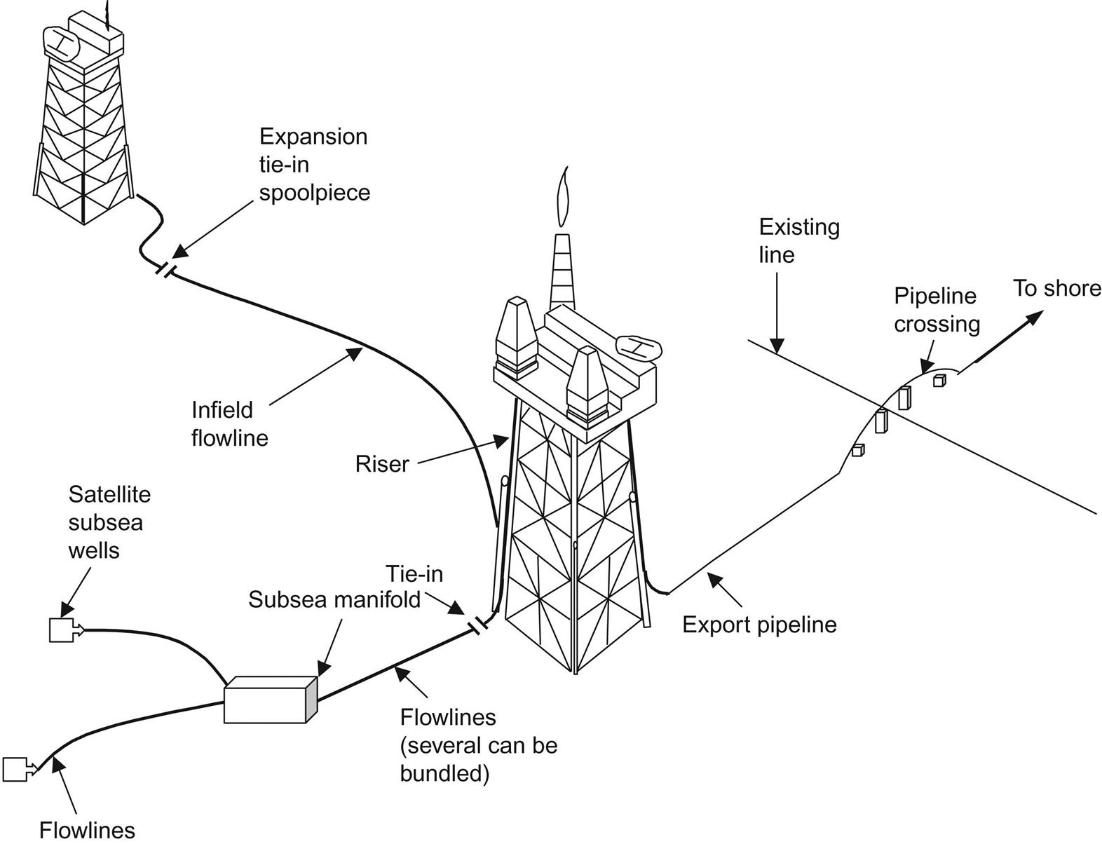
A flowline is a segment of steel pipe conveying the produced fluids from a wellhead, through a production manifold as necessary, to a fluid separator of a surface facility. Fig. 1.9 shows applications of flowlines in offshore operations. It indicates flowlines transporting oil and/or gas from satellite subsea wells to subsea manifolds, flowlines transporting oil and/or gas from subsea manifolds to production facility platforms, infield flowlines transporting oil and/or gas from between production facility platforms, and export pipelines transporting oil and/or gas from production facility platforms to shore.
1.5 Safety Control System
The purpose of safety systems is to protect personnel, the environment, and the facility. The major objective of the safety system is to prevent the release of hydrocarbons from the process and to minimize the adverse effects of such releases if they occur. This can be achieved through the following:
The modes of safety system operation include:
Protection concepts and safety analysis are based on undesirable events, which include:
a. Increased input flow due to upstream flow-control device failure
b. Decreased output flow due to blockage
c. Mechanical failure due to temperature change, overpressure and underpressure, and external impact force
a. Increased input flow due to upstream flow-control device failure
b. Decreased output flow due to blockage in the liquid discharge
a. Increased input flow due to upstream flow-control device failure
b. Decreased output flow due to blockage in the gas discharge
a. Outlet flow-control device (e.g., choke) failure
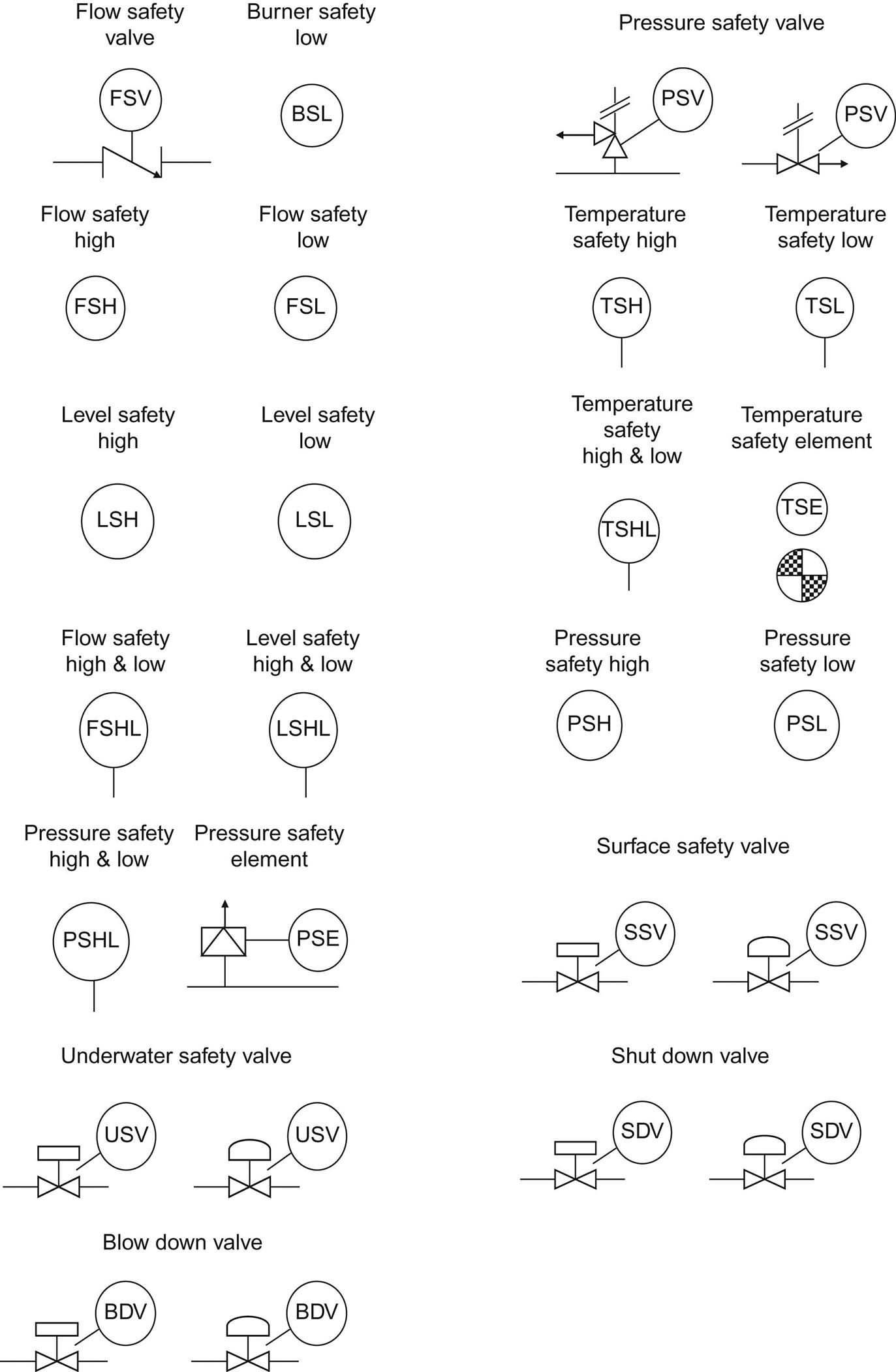
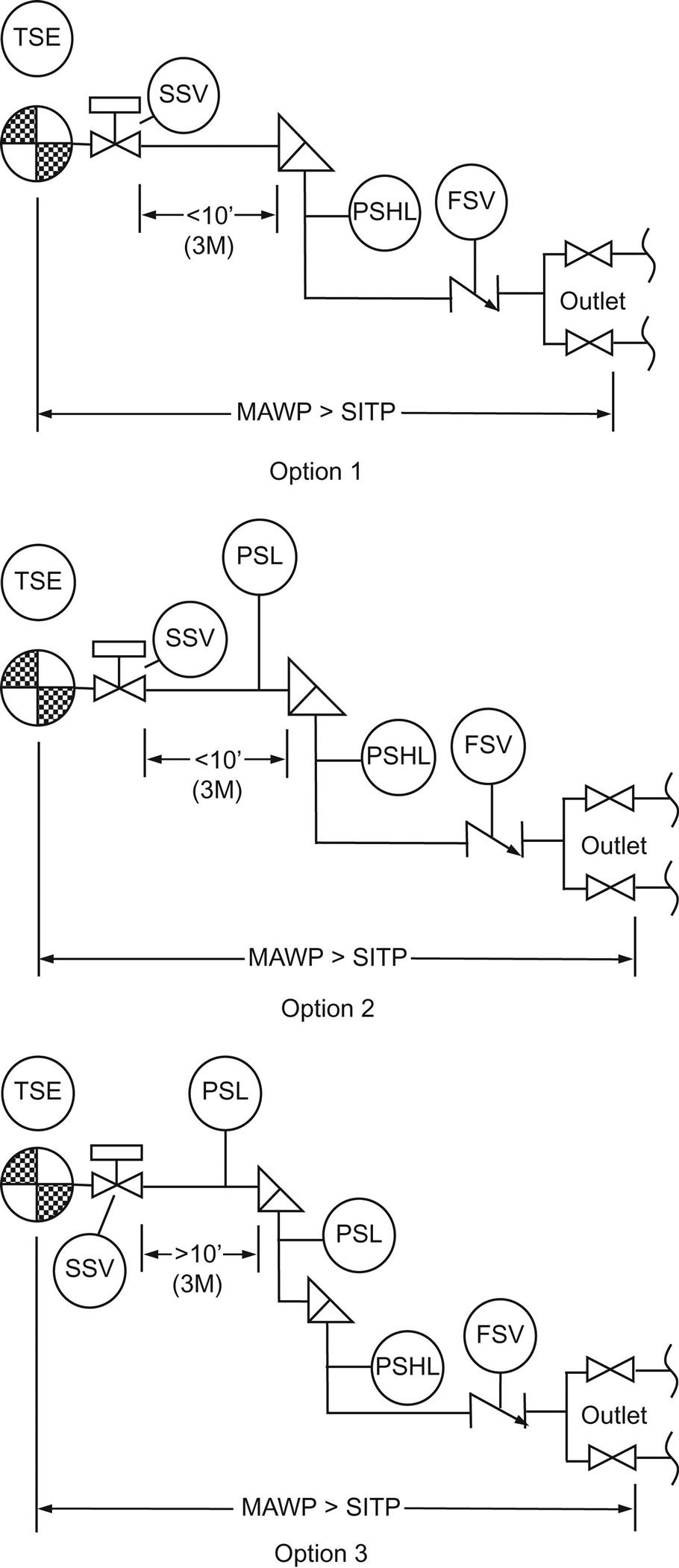
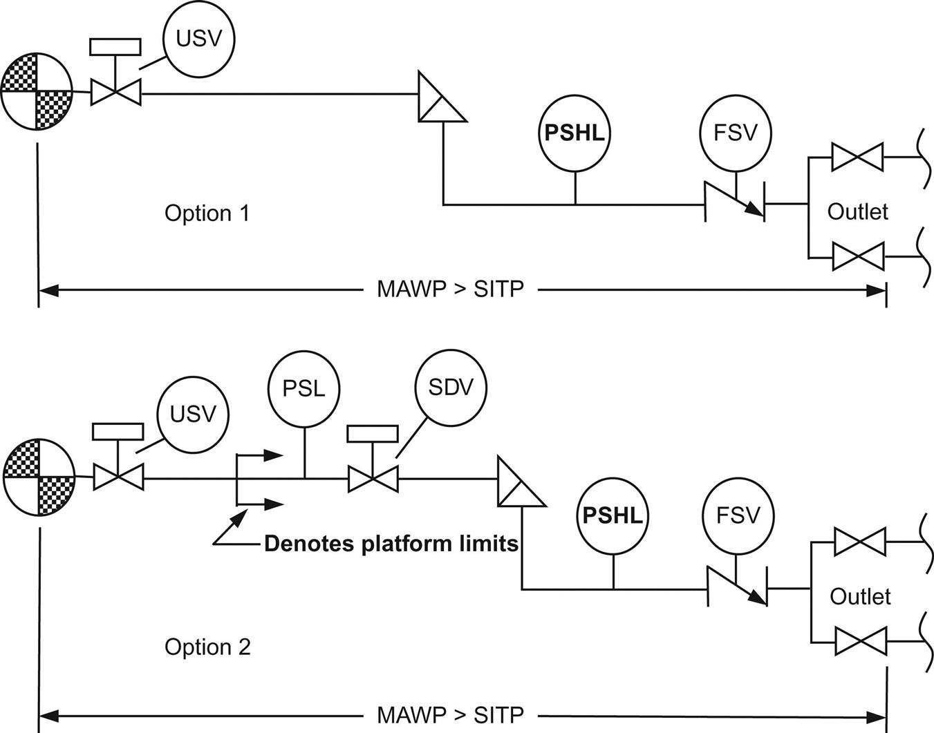
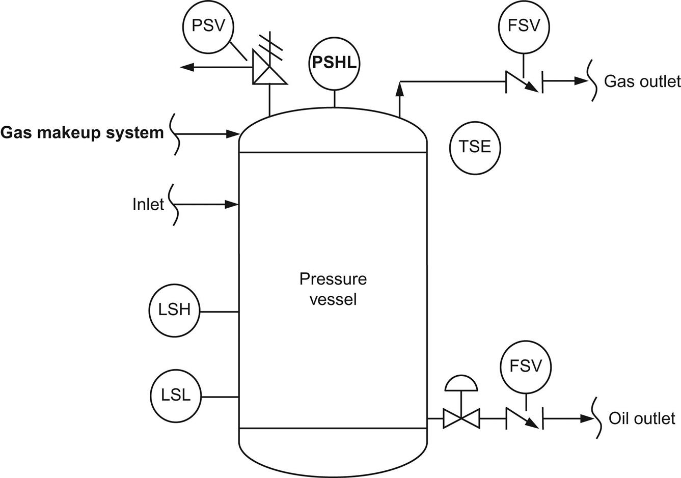
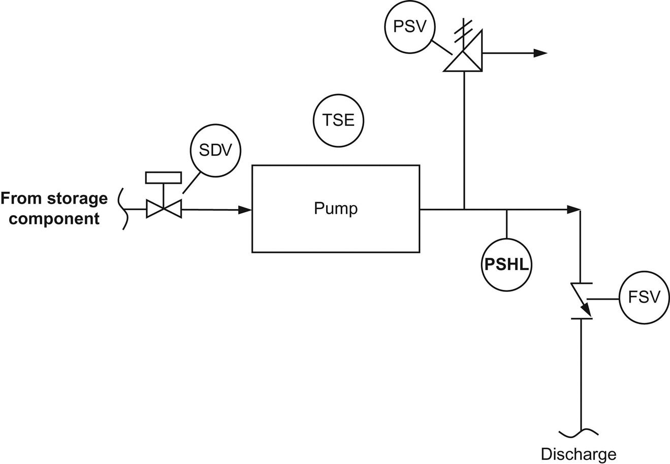
Fig. 1.10 presents some symbols used in safety system design. Some API-recommended safety devices are shown in Figs. 1.11 through 1.15 (API, 1987b).


1.6 Summary
This chapter provided a brief introduction to the components of petroleum production wells. Working principles, especially flow performances, of the components are described in later chapters.
Problems
1.1. What is the role of an oil production engineer?
1.2. Is the tubing nominal diameter closer to tubing outside diameter or tubing inside diameter?
1.3. What do the digits in the tubing specification represent?
1.4. What is a wellhead choke used for?
1.5. What are the benefits and disadvantages of using down-hole chokes over wellhead chokes?