5 Stitching - Increasing Image Coverage
The most common use for stitching is to construct a panoramic image from a series of interlocking source shots. Simple panoramas can be constructed with just a few shots using the techniques described in this chapter. Complex panoramas require more in-depth knowledge and additional equipment, such as a panorama head for your tripod.
In this book, we will limit ourselves to describing how to construct simple panoramas containing no more than six source photos, and to other situations in which stitching can be a useful tool. Such situations often include the creation of a high-resolution merged image similar to those described in chapter 2, or to create a composite image of a subject that is simply too large or too close to be captured in a single image using the available equipment.
5.1 Shooting Techniques for Stitching Applications
![]() Although there are a number of different types of images which can be constructed using stitching, some of which are not panoramas in the classic sense, we will nevertheless call all of our resulting images “panoramas” in order to keep things simple.
Although there are a number of different types of images which can be constructed using stitching, some of which are not panoramas in the classic sense, we will nevertheless call all of our resulting images “panoramas” in order to keep things simple.
Although the manufacturers of stitching software often claim that their programs work well with images shot hand-held, experience has shown that images shot using a tripod yield better results. Even without considering the shifts that hand movements can cause, the algorithms required to produce smooth, accurate seams between the individual component images of a panorama require large amounts of computing power. As we have recommended throughout the book, shooting with a tripod will always help you to improve the quality of your results.
Here, we will only be dealing with simple panoramas consisting of between two and six source images. We also assume that the panoramas we create will only consist of one or two horizontal rows. You do not, of course, have to stick to these restrictions, but it helps to keep things simple while you are still learning a new technique. We will begin by constructing panoramas that consist of a single horizontal or vertical row of images.
The general characteristics of the component images should be as follows:
A. They should be as sharp as possible. This will help the program to establish which parts of the images to overlap. A tripod will help you get better results, as it will eliminate camera shake and allow for longer exposure times, smaller apertures, and thus greater depth of field.
B. All source images should be shot using the same aperture setting. We recommend setting the shutter speed and aperture manually to ensure consistent exposures.
C. All source images should be shot using the same distance setting, as far as is possible. We recommend using manual focus, as autofocus can too easily produce images with slightly different magnifications.* Differences in distance settings are less problematic when using smaller apertures.
D. Neighboring images should overlap by about 25–35%. This is the amount required for a stitching program to reliably identify congruent points and the areas which should overlap in the individual images.
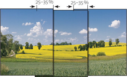
Figure 5-1: Neighboring images should overlap by about 20–30%.
E. You should avoid shooting by moving the camera parallel to your scene (sideways), and you should generally shoot your images by panning the camera from left to right, or vice versa. Ideally, you will rotate the camera about its optical center, also known as the no-parallax point. This point is also sometimes (incorrectly) referred to as the nodal point. The no-parallax point is the point within the camera/lens construction where hypothetical rays of light cross at a given distance setting.
Unfortunately, this optimum point is not usually positioned directly above the camera’s tripod socket or the tripod’s quick-release plate.
If you simply move your body while shooting hand-held, the distance between the optical center and the axis around which the camera is being rotated becomes even greater. If you have to shoot hand-held, it is best to rotate the camera around an imaginary axis positioned as close as possible to the front element of the camera’s lens. Another effective tool for such situations is simple monopod.
If, however, your subject is far enough away (landscapes at a distance of forty or fifty feet, for instance), then the effect of the camera being rotated around a non-ideal axis will not have a very noticeable effect on your stitched results. However, if you are shooting a more immediate environment, such as the interior of a room, the resulting parallax shifts can have visible negative effects.
F. Try to allow as few changes as possible to take place within the frames. Moving objects such as cars or people passing by, or moving clouds, can cause problems if they are in one of the overlap areas. Also try to make sure the lighting conditions remain as consistent as possible throughout your source sequence.
The sum of all these points presents a substantial photographic challenge, so we will now address each point individually.
We aim to make useful suggestions, rather than write hard and fast rules, and it is often possible to shoot usable panoramas without adhering to all of the guidelines we describe. Smaller panoramas can often be successfully shot hand-held.
A. Using a Tripod
This should really be self-explanatory. Our best advice is to use the sturdiest, most robust tripod you can find. Your tripod and its head need to be strong enough to support your camera/lens combination adequately, and it should ideally have a built-in scale for measuring angles of rotation and tilt accurately. Hanging a backpack from a hook on a tripod’s center post can also increase stability. Some panorama heads and specialized brackets also allow the whole assembly to lock in to specific preset angles. This is a useful addition when shooting panoramas, and can be seen in heads manufactured by Novoflex [40], Manfrotto [52], and Nodal Nija [51]. The downside of such devices is often the price – usually somewhere between $200 and $1,000 – and they can be quite heavy, which can be a disadvantage if you have to carry your equipment over large distances to your shoot, or if your tripod is part of your carry-on baggage on a flight.
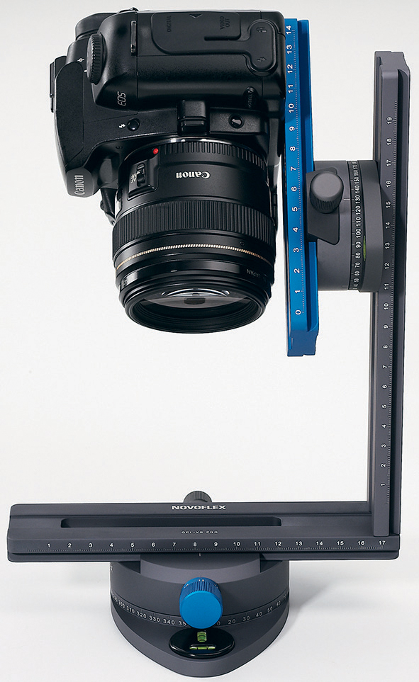
Figure 5-2: A typical 3-D panorama head (here, the Novoflex Panorama VR-System Pro).
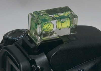
Figure 5-3: A spirit-level attached to the camera’s flash shoe can help to ensure that the camera remains perfectly level.
There will almost always be some vertical displacement between the individual shots in a panorama, which means they won’t always line up perfectly at the top or bottom. It is therefore important to allow sufficient space at the edges of your shots for cropping once the images have been aligned. When shooting for a horizontal panorama, it is often advisable to take your shots in portrait mode (with the camera rotated to a vertical position), and simply to take more shots.
When shooting for horizontal panoramas, another useful tool is a small spirit-level, which can be purchased for around $15 and which can be mounted on the camera’s flash shoe. Here, you need to make sure that the flash shoe is parallel to the camera’s optical axis.
One way to consistently reduce camera shake is to use a cable-release or an infrared or remote-controlled remote release instead of the shutter button. There are a number of inexpensive alternatives for most camera models available. You can also use the self-timer, but this does take extra time, and makes it more difficult to time your shot to avoid moving objects within the frame.
An even greater help is mirror lock-up – a function which is often available in modern bridge or DSLR cameras. (For further information on how to use mirror lock-up, check your camera’s manual.) Mirror lock-up allows you to lock the camera’s mirror in its raised position before the shutter is actually released. There are two ways cameras deal with this process:
▸ With some older cameras, such as the Nikon D100, the shutter button is pressed with the mirror lock-up function activated. The camera then raises the mirror and waits a moment for the vibrations this causes to subside before releasing the shutter. This method also works very well if you are using a cable-release, but the pause needs to be at least two seconds long for it to be effective.
▸ Other cameras raise the mirror when the shutter button is pressed once and make the actual exposure only when the shutter button is pressed a second time. Canon uses this technology, and it is also used in newer Nikon cameras, such as the D200. Here, you have to determine the time lag between the two actions yourself. Two or three seconds should be sufficient to allow all vibrations in your camera/tripod assembly to subside. Feel free to experiment, but remember, you won’t really be able to see how your results are affected until you see them enlarged on your computer monitor.
Of course, using mirror lock-up only makes sense if you are also using a tripod (or other support) and a remote release. Wind is always a problem, regardless of how you shoot.
B. Obtaining the Correct Exposure
Greater depth of field in your images is an advantage for nearly all the processes described here. We therefore recommend that you always use a smaller aperture in the range between f/8 and f/16 (while bearing in mind the “optimum aperture”, which we discussed in section 4.2 on page 56).
If moving objects such as people, vehicles, water, or leaves appear in a scene, it will be necessary to use shorter shutter speeds and smaller aperture values (i.e., a larger aperture) in order to avoid motion blur.
When you are shooting for stitching purposes, it is important that your exposures remain consistent from frame to frame, in order to keep the transitions between the individual shots smooth. You can keep your exposures constant by using your camera’s manual (M) exposure control function.
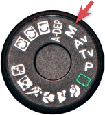
Figure 5-4: Set your camera to “Manual” when shooting stitching sequences.
We then start by using the camera’s automatic exposure metering to meter all the shots in the sequence, and then switch back to manual to make a constant setting for all shots in the sequence, based on the best average of the automatically metered values. It is better to set your exposure to account for the highlights in your scene rather than for the shadows. As we are working with a relatively short sequence, this kind of discrepancy shouldn’t cause too many problems. If your camera has an Auto ISO function, please disable it.
![]() If you are working with a cable-release and an SLR camera, remember to cover the eyepiece when you are not looking through it. Otherwise, stray light can enter the camera body and cause your images to look washed-out. Stray light can also disrupt the camera’s light metering systems.
If you are working with a cable-release and an SLR camera, remember to cover the eyepiece when you are not looking through it. Otherwise, stray light can enter the camera body and cause your images to look washed-out. Stray light can also disrupt the camera’s light metering systems.
Shooting with your back to the sun or with an overcast sky makes it easier to achieve consistent exposures, and you should always use a lens hood to reduce the effects of stray light and ensure maximum contrast.
Do not use polarizer filters or flash when shooting for panoramas (especially if you are using a wide-angle lens), as these both tend to cause irregularities in brightness and color which will make it difficult to achieve smooth stitching effects.
A slightly overcast or “busy” sky always looks better in broad landscape panoramas than simple, bright sunshine or a low-contrast, clear blue or white sky.
If, however, the range of contrast in a scene is too great to capture in a single shot or sequence of shots, you can always turn to bracketing techniques for assistance. This involves taking several shots of each portion of your scene using a constant aperture value and differing shutter speeds. You can then merge the bracketed shots into HDRI images which can then be stitched together to make your panorama. We will discuss this approach in depth later.
C. Consistent Distance Settings
Because different distance settings lead to variations in framing as well as depth of field (which can change the apparent size of individual elements in a shot), it is important to take all the shots in a stitching sequence using consistent distance settings. It is best to focus manually, but you can use autofocus for landscape shots, provided that there are no objects in the foreground which can mislead the autofocus system.
![]() A number of calculators specifically designed to determine hyperfocal distance are available online. One example is: www.onlineconversion.com/field_of_depth.htm
A number of calculators specifically designed to determine hyperfocal distance are available online. One example is: www.onlineconversion.com/field_of_depth.htm
If there are no nearby objects in the foreground, it is best to set your lens to the hyperfocal distance that applies to the aperture you are using. This is the closest distance at which your lens can be focused while keeping objects at infinity acceptably sharp. It depends on the focal length and the aperture being used. A 50 mm lens set to f/5.6, for example, will have a hyperfocal distance of about 50 feet (for a full-frame camera). See also the formula in the sidebar and table 5-1.
For the more mathematically inclined, here is the formula used to calculate hyperfocal distance:
In this case:
hfd: |
hyperfocal distance (in feet) |
f: |
the actual aperture (not the 35 mm equivalent) |
d:u |
circle of confusion diameter (mm) |
Aperture value: i.e. f/2.8 → 2.8
D. Image Overlap
This is the easy part: make sure the edges of neighboring images in your sequence overlap by 25–35%. More is also acceptable, but once the overlap exceeds 50%, your images will start to overlap with the next image, causing the stitching process to fail.
Pick an object (when panning from left to right) which is about a third of the way from the right-hand edge of your frame. When shooting the next image in the series, pan the camera so that this object is located almost at the extreme left-hand edge of the next shot. You don’t have to be over-precise here, at least if you are only shooting single-row panoramas. It is also advisable to do a test run to establish how many shots you will have to make before you actually start shooting. Table 5-2 can help you make a rough guess, but it doesn’t take a specific degree of overlap into account.
Focal Length |
Aperture |
Hyperfocal Distance |
10 mm |
f/2.8 |
3.9 feet |
10 mm |
f/5.6 |
2.0 feet |
10 mm |
f/11 |
1.0 feet |
24 mm |
f/2.8 |
22.5 feet |
24 mm |
f/5.6 |
11.2 feet |
24 mm |
f/11 |
5.7 feet |
35 mm |
f/2.8 |
47.8 feet |
35 mm |
f/5.6 |
23.9 feet |
35 mm |
f/11 |
12.2 feet |
50 mm |
f/2.8 |
97.6 feet |
50 mm |
f/5.6 |
48.8 feet |
50 mm |
f/11 |
24.9 feet |
75 mm |
f/2.8 |
219.7 feet |
75 mm |
f/5.6 |
109.9 feet |
75 mm |
f/11 |
55.9 feet |
If your scene includes any finely detailed critical elements, it might also be necessary to take an extra shot with these elements positioned in the center of the frame (where no overlapping will occur). You can then exclude the extra shot from your initial merge and crop your critical object into the merged image to compensate for any inaccurate merging that the stitching program may have produced.
Moving objects only really present a problem if they lie within an overlap area or if they are actually blurred. Moving objects in the center of an image do not present us with any additional difficulties.
If you are stitching a panorama that consists of more than two source images, you will first have to decide which of your shots is to be your central image in the resulting panorama. You should then compose your panorama using this image as a central point. This will ensure that your chosen central image will be least affected by the optical distortions stitching produces.
These values apply for a crop factor of 1.0 and a 0.03 mm circle of confusion diameter. For other crop factors, simply multiply the distance by the crop factor.
Because shooting landscape panoramas almost inevitably produces vertical shifts in an image sequence, we recommend that you shoot with your camera in portrait (upright) mode. Otherwise, it will be necessary to align the camera almost impossibly accurately on its horizontal axis. In order to shoot vertically, however, you will need to mount your camera on an L-plate – simply rotating the tripod head through 90° would position the camera well outside the vertical nodal point.
You can either build your own L-plate out of aluminum (see [50] for instructions) or buy one. Such accessories are available nowadays as high-quality professional equipment. Novoflex [40], for example, offers the model illustrated in figure 5-5 for about $80. Some advanced panorama heads also have built-in L-plates.
We use an L-plate manufactured by the American company Really Right Stuff [41] for our panorama shots (see figure 5-6). This model is a little more elegant than the Novoflex one shown in figure 5-5. It is, however, less flexible because you have to purchase a different one for each type of camera, and it doesn’t accommodate battery grips.
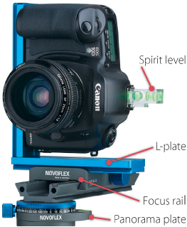
Figure 5-5: A camera mounted vertically on a Novoflex L-plate, which is itself mounted on a focus rail, mounted on a Novoflex panorama plate. The panorama plate ensures precise camera rotation.
L-plates are not only useful for mounting your camera in portrait mode, they also allow you to switch quickly between portrait and landscape modes, and to align the camera’s vertical optical axis with the pivotal point of your tripod.
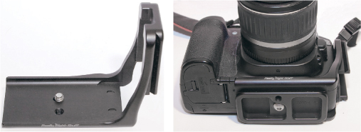
Figure 5-6: This Really Right Stuff L-plate allows you to switch quickly between portrait and landscape shooting modes.
Table 5.2: Horizontal Angle of View for Various Lenses* |
|||
Focal Length |
Full Frame (approx. 24 × 36 mm) |
APS-C Sensor (Crop Factor 1.5) |
APS-C Sensor (Crop Factor 1.6) |
Wide-angle |
|||
10 mm |
245° |
150° |
140° |
15 mm |
160° |
106° |
100° |
20 mm |
95° |
63° |
59° |
35 mm |
51° |
34° |
32° |
Normal |
|||
50 mm |
45° |
30° |
28° |
75 mm |
30° |
20° |
19° |
Telephoto |
|||
100 mm |
24° |
16° |
15° |
150 mm |
16° |
11° |
10° |
200 mm |
12° |
8° |
7° |
E. The Optical Center – Locating the No-Parallax Point
If you do not rotate your camera precisely around the optical axis while shooting your panorama, your results will be subject to parallax shift. This means that objects located at varying distances from the camera will change in their relative positions to one another from image to image. This effect makes effective merging to a single image difficult or impossible, as illustrated in figure 5-9. If, however, you rotate the camera around the optical center of your camera/lens assembly, this effect will not occur. Although the term nodal point does not quite correctly describe the optical center, it has become an accepted standard which we will use in the following sections. A more accurate term that is also used in this context is no-parallax point.
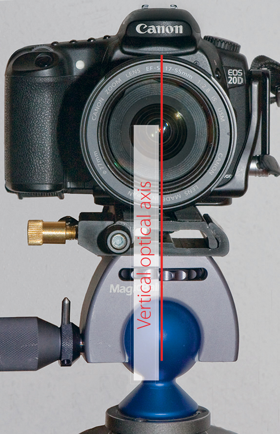
Figure 5-7: The nodal point lies vertically over the middle of the lens axis.
Where exactly is the nodal point for a particular camera/lens combination? Vertically, this point lies on the so-called optical axis of the camera/lens and is located in the center of the lens (see figure 5-7). It is important to ensure that this point is located directly above your tripod’s center of rotation. If you are using a tripod with a quick-release head, it can be useful to use a quick-release plate that is larger than necessary to allow you some leeway in positioning your camera on the tripod itself.
Establishing the horizontal position of the no-parallax point is more difficult. Our first reference point is the position of the aperture within the lens. The aperture mechanism is not necessarily located directly at the nodal point of a lens, but is usually quite close to it.
The position of the no-parallax point in fixed focal length lenses is independent of the current focus setting. In the case of zoom lenses, the no-parallax point can move, depending on the focal length setting. In the following example, we will start at the widest possible focal length setting. Once you have found the nodal point (we will tell you how shortly), it remains largely independent of your distance setting, and only needs to be established once. The fine-tuning for an initial rough guess can be conducted as follows:
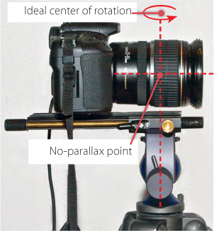
Figure 5-8: In the case of this camera/lens combination (Canon 20D + Canon 17–55 1:2.8 IS USM), we have found the nodal point to be located at the marked spot. With the help of the focus rail, we have located it directly above the tripod’s center of rotation.
1. Find two objects with vertical edges. The first object should be as close to the camera as possible, and the second should be further away. For simplicity’s sake, line these edges up to coincide in the center of the frame. Arrange the tripod, tripod head, and camera so that the vertical lens axis is directly above the center of rotation of your tripod, and so that the camera remains perfectly level when rotated. If you are using a focus rail to set the horizontal position, make sure the camera is situated parallel to the rail. Now position your camera with your estimated nodal point horizontally above the center of rotation.
2. Next pan the camera to the left and observe the relative distance between your two vertical edges. If the coverage doesn’t change as the camera turns, then you have already found the correct point. However, if the foremost edge apparently moves to the right when you pan to the left, then the nodal point lies in front of the current estimated position.
If the foremost edge moves to the left when you pan to the left, then the nodal point lies further back (see figure 5-9). Adjust your camera position based on these tests and repeat the steps described until you have located the exact nodal point.
![]() If you pan to the right, then both instances are reversed.
If you pan to the right, then both instances are reversed.

Figure 5-9: When panning to the left (image to the right), the red pen has moved to the right in relation to the beam in the shelf. In this case the optical middle point lies in front of the current turning point, so the camera needs to be pushed back some.
We were often surprised at how far forward the nodal point actually lies – often near the front edge of the lens. In the case of our Canon 18–55 mm zoom lens (a standard bundled lens), the nodal point barely moved between the two extreme zoom settings.* For this zoom lens, we really can make do with a single no-parallax point for objects which are not too close to the camera. Once you have found the no-parallax point, mark it on the side of the lens with a piece of tape or nail polish. In the case of push-pull zooms and zooms with a greater degree of extension, the nodal point can often move significantly from one focal length setting to another.
F. Moving Objects
Moving objects, such as people, vehicles, or birds, are only problematic when they are located in the overlapping areas of your source images. Leaves moving in the wind or fast-moving clouds can also cause problems. If such objects appear in an overlap area, then ghosting can occur in the resulting overlap areas. It is nevertheless amazing how well modern stitching software handles moving objects.
One way to reduce the effects of moving objects is to use a stamp tool to remove them before you begin the merge process. If you decide to use this technique, you should take several shots of the relevant part of your scene, so that you have sufficient “clean” material for subsequent stamping into your image. Another option is to use the PhotoAcute Remove moving objects from the scene command.** PhotoAcute recommends using at least five images of the image area in question. You can then create a “clean” image of the part of your scene containing moving objects using just the Remove moving objects function, and build it into your panorama using your chosen stitching tool.
Sometimes, however, it’s simpler to retouch the finished panorama and to use the Photoshop Clone tool to remove any remaining ghosting or shadows.
5.2 Image Preprocessing
We recommend that you shoot your images in RAW format.* However, most stitching programs will require you to convert your images to TIFF or JPEG before processing. If your stitcher supports 16-bit files, you should use 16-bit output in your RAW converter, even if your final image output is only going to be 8-bit. This is because your images will be rotated, stretched, compressed, and skewed during stitching, and 16-bit source material provides you with a greater reserve of image detail to work with. However, if you are working with limited RAM capacity, working with 8-bit images during the whole workflow will halve your main memory requirement.
As already mentioned, you should process your images as consistently as possible in the RAW converter. This applies to all image aspects, including white balance, color and exposure correction, and other optimization processes (such as vignetting or chromatic aberration corrections). If you decide to crop your images during preprocessing – for example, to remove a bland sky – then make sure you crop exactly the same areas in all of your images. Most stitching programs require all images to have identical pixel dimensions.
Some stitchers have automatic, profile-based lens distortion, chromatic aberration, and vignetting correction functionality. If your stitcher has these functions, you should avoid making these types of corrections using a RAW converter, as they would then have to be performed manually. Programs based on the Panorama Tools application (such as Hugin, PTGui, or PTMac) include the above mentioned capabilities.
It is sometimes an advantage to use your RAW converter to sharpen your images. This can help you (and your software) to identify the common points and overlap areas in your panorama. It is important to make sure that any presharpening is consistent and not over done, as you will nearly always apply some final sharpening once your stitched panorama is complete.
When applying any of the adjustments described here, you should always start by correcting your central image – i.e., the one with the most important details. You can then apply the same corrections to all other images in the sequence.**
In Photoshop, use the Bridge image browser to select all the images in a sequence and start Adobe Camera Raw (ACR) using the right-click context menu for the selected images. ACR will then open the selected images and display them in the Filmstrip sidebar. Select the central image and optimize it. Then select the rest of your images (by holding down the ![]() -button) and click on Synchronize. ACR will then ask which settings should be transferred.*** You can select either all settings, or only those which you have actually changed in the central image. Save your images using the Save Images button – preferably all in the same folder.
-button) and click on Synchronize. ACR will then ask which settings should be transferred.*** You can select either all settings, or only those which you have actually changed in the central image. Save your images using the Save Images button – preferably all in the same folder.
If you are using Lightroom, you should optimize the central image before selecting the rest of the sequence in the Filmstrip or Grid view. You can then click the Synchronize button. As in Adobe Camera RAW, a dialog box will prompt you regarding which settings you want to transfer.
If you are using a different RAW converter, you will need to consult the user manual in order to find out exactly how to transfer your changes to the other images in your sequence.
Organizing Your Images
Selecting images in Adobe Bridge or Lightroom and automatically loading them into the Photoshop Photomerge (stitching) function is a simple process. When working on larger projects, we recommend that you copy your preprocessed source files to a dedicated folder, which will later also contain the stitched image. If you are making more than one panorama, use a separate folder for each. A large and complex panorama can quickly become an independent project, and some stitchers allow for discrete project data, such as type, start date, or correction information to be saved in a separate project file. This is a useful reference and can save you having to start from scratch if things do not go according to plan. As explained in section 2.1, you should name your files using conventions which allow them to be displayed in the correct sequence. If you followed our recommendation to separate your individual panorama sequences using a blacked-out frame or a picture of your hand, you can now delete these with confidence.
5.3 Types of Panorama (Projection Forms)
The technicalities of the stitching process would be fairly simple if it were possible to move the camera paraxially between shots. However, instead of a sideways (or vertical) shift, our examples involve rotating the camera around a single axis, leading to distortion in some parts of the resulting images. It is therefore necessary to tell the stitching software which type of projection you want to use before processing begins. The best projection type to use depends in part on the number and arrangement of the individual images involved, and in part on the purpose of the final image. There are four typical and popular projection types, and many more available in various stitching programs:
1. Linear Projection.
Here, the images are projected onto a flat surface. This type of projection is also referred to as rectilinear projection, and in Photoshop it is called Perspective Layout. While the central image remains largely untouched, the images to the left and right of it are compressed and/or stretched, and the further an image is from the center, the greater the artificial angle of view will be, causing even greater distortion. Figure 5-11 should clarify the reasons for this. The angle of view to be covered by the panorama here should not exceed 100–120° – otherwise, the edges of the image will become extremely distorted. Some distortion is already visible in figure 5-11.
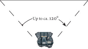
Figure 5-10: Camera panning for a linear projection.

Figure 5-11: Linear projection
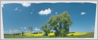
Figure 5-12: This image resulting from a cylindrical projection shows typical barrel distortion.
2 Cylindrical Projection
This type of projection is based on the concept of an obsever placed in the center of a circular room on whose walls the image is projected. Cylindrical projections also cause image distortion when they are stitched, in this case most noticeably in the barrel distortion evident in the individual images (see figure 5-14). This distortion is the result of a flat image being projected onto an imagined, cylindrically-shaped surface.
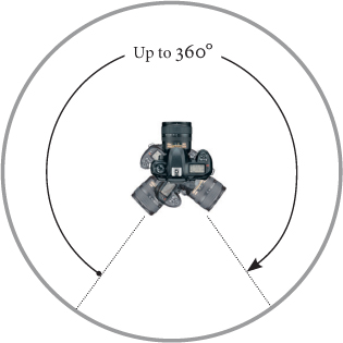
Figure 5-13: Cylindrical projection is suitable for images and projection surfaces with a circumference of up to 360°.
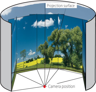
Figure 5-14: Cylindrical projection
To shoot images for a cylindrical projection, the photographer simply rotates around his/her own axis, resulting in a sequence of images which can cover an angle of view of all the way up to 360°. If you want to present your image “in the round” in a presentation cylinder or – with appropriate preparation – in a digital format which allows the user to virtually turn around within a scene, the stitcher will also need to overlap the first and last images of the sequence. Not all stitchers are capable of realizing this type of 360° overlap.
This type of projection method assumes that the observer is situated in the center of a sphere and that the image is projected onto the sphere’s interior surface. Specialized software is necessary to view this type of projection, and to allow the viewer to virtually rotate about his/her own vertical and horizontal axes and to “look up and down” within the image.
Photoshop only supports this type of projection in its latest CS4 version, so we will not go into any further detail at this point.
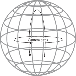
Figure 5-15: Spherical panoramas require the camera to be rotated around two axes.
4. No Projection
This is also a valid approach if the source images have been shot either by moving the camera parallel to the subject plane, or by moving the subject horizontally in relation to the camera lens – as is often the case in microphotographic situations. The Windows version of Helicon Focus offers a function for stitching this type of panorama. Photoshop calls this type of stitching Reposition Only. In this case, the stitcher simply searches for appropriate connection points, arranges the images based on these, and performs an overlay process using a blending mask.
We will be sticking to simple linear projection for our examples, covering angles of view of up to 100–120°, which is quite sufficient for our purposes. This type of panorama also requires the use of less specialized equipment, and is most suitable for our ultimate goal of a printed image.
5.4 Merging Images Using the Photoshop “Photomerge” Command
Our first example uses the five source images displayed in figure 5-16. As you can see, these contain plenty of overlapping areas. These images were shot hand-held in JPEG format using a compact camera.
The simplest way to start Photoshop’s Photomerge feature is to start it from Bridge or Lightroom. In Bridge, select the images you want to stitch and start Photoshop using the following menu sequence: Tools ▸ Photoshop ▸ Photomerge.
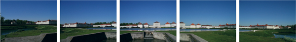
Figure 5-16: Five source images of the Nymphenburg Palace in Munich. They were shot hand-held in JPEG format using a compact camera.
![]() Currently, Photoshop only allows you to merge images which have the same pixel dimensions. Keep this in mind when preprocessing and/or cropping your source images.
Currently, Photoshop only allows you to merge images which have the same pixel dimensions. Keep this in mind when preprocessing and/or cropping your source images.
The same option has been available since version 2 of Adobe Lightroom. In this instance, you also need to select the images in the grid view and then load them into the Photoshop panorama function using a right-click and Edit in ▸ Merge to Panorama in Photoshop. There, you can use the Browse dialog to select images.
If you use Bridge or Lightroom to start the Photomerge function, RAW images are automatically converted to TIFF or PSD before they are transferred. Bridge always exports 8-bit TIFF files, and Lightroom exports to the format selected in the program’s preferences for transferring files to Photoshop for editing.
You can also start Photomerge directly in Photoshop using File ▸ Automate ▸ Photomerge. There, you can use the Browse dialog to select your source images.
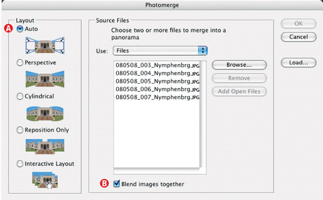
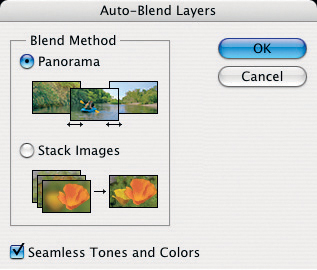
Figure 5-17: Having selected your source files, you can define the type of layout (projection) you want to use, and whether Photoshop should blend the images together (the screenshot here is from Photoshop CS3).
In all three cases, the dialog shown in figure 5-17 will be displayed. Start by selecting the type of layout (projection type) you want to use ![]() , and then select whether or not you want Photoshop to blend the images together
, and then select whether or not you want Photoshop to blend the images together ![]() . We recommend that you select Auto (
. We recommend that you select Auto (![]() ) and activate option
) and activate option ![]() for your first few attempts. We will go into more detail on this topic later.
for your first few attempts. We will go into more detail on this topic later.

Figure 5-18: Our Layers palette after loading and aligning our source images.
When you click OK, Photoshop starts to perform the basic operations necessary to create a panorama: it loads the images in sequence in individual layers, aligns them appropriately, corrects the individual images based on the type of projection you have selected, and creates any necessary layer masks. Don’t let the resulting flurry of activity in the program window irritate you. The merge process can take quite a while, depending on the number and size of your source images, as well as the selected projection type – but this is not uncommon when using multishot techniques, and is something we have gotten used to at this point.
Figure 5-18 shows the layer palette after the operation is complete. Figure 5-19 shows the accompanying Photoshop window.
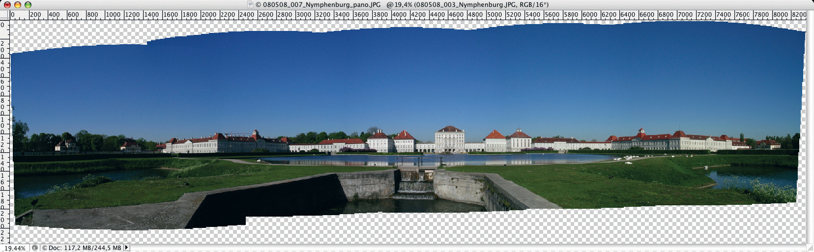
Figure 5-19: The results of the first stitching run. Because the shots were taken without using a tripod, the panorama shows a good deal of vertical offset between the individual images.
The individual images can still be moved if necessary at this point. You can shift the individual elements by selecting the appropriate layer from the palette and moving using the ![]() tool, or you can use the Edit ▸ Free Transform command to shift, rotate, or even distort each image separately. This will not usually be necessary, as Adobe continues to improve the Photomerge module, and the CS3 version produces excellent results without the need for any user intervention.
tool, or you can use the Edit ▸ Free Transform command to shift, rotate, or even distort each image separately. This will not usually be necessary, as Adobe continues to improve the Photomerge module, and the CS3 version produces excellent results without the need for any user intervention.
Even the automatic brightness adjustment in our example has turned out pretty well, although the source images were shot (contrary to our earlier recommendations) in automatic exposure mode. In this situation, it helped us that the sun was situated behind the photographer, and that the white walls of the building were relatively distant from the camera. Figure 5-20 shows the same resulting image that Photoshop produces if the Blend images together option is deactivated.* We recommend leaving this option activated as part of your standard procedure.
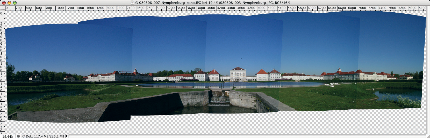
Figure 5-20: With the option “Blend images together” deactivated, obvious differences in lighting are visible at the seams within the panorama.
We decided to discard the second version and proceed using the first. It is clear that even this excellent merged image will require some post-processing.
Obviously, we will need to crop the final image using the cropping tool ![]() You can also realign the image (if, for example, the horizon isn’t quite level). To rotate your image, simply move the cursor outside the image area – this will automatically start the rotate tool (the cursor will look like this:
You can also realign the image (if, for example, the horizon isn’t quite level). To rotate your image, simply move the cursor outside the image area – this will automatically start the rotate tool (the cursor will look like this: ![]() ), allowing you to rotate your merged image freely to the required position.
), allowing you to rotate your merged image freely to the required position.
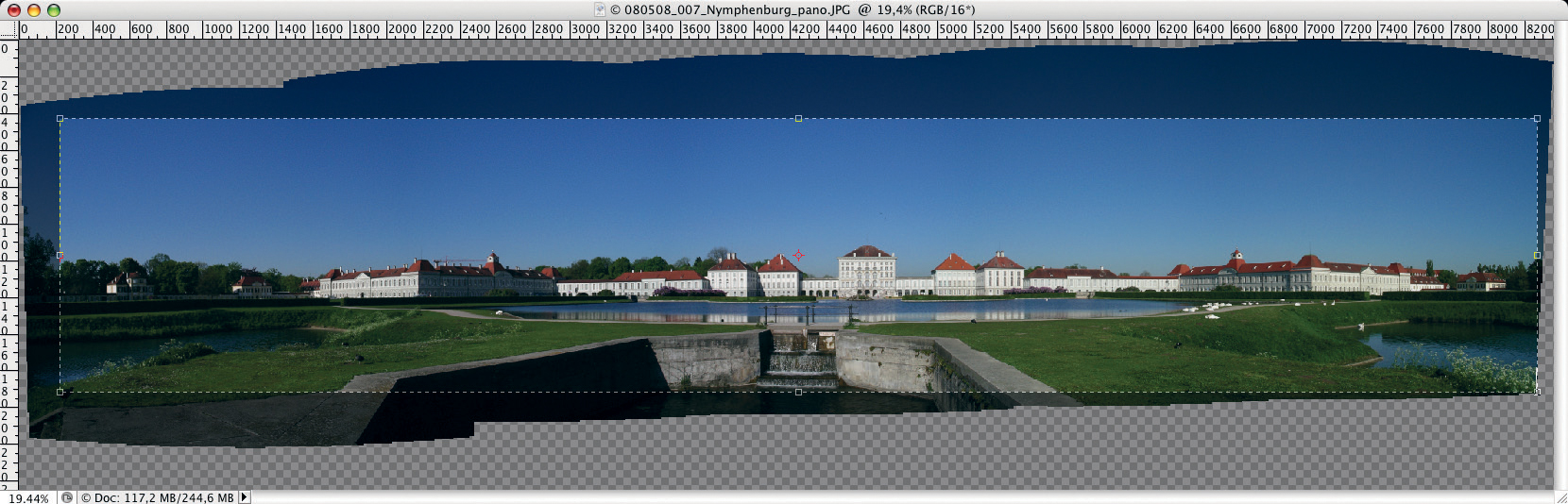
Figure 5-21: Before saving, crop the image to remove any uneven or unexposed borders.
If you have difficulty finding the right angle of rotation, you can use the Ruler ![]() tool to draw a straight line through your proposed horizon. You can then use the Rotate Canvas command (Image ▸ Image Rotation ▸ Arbitrary) to align your image. The resulting dialog will display the angle you have just measured using the Ruler tool, which you can adjust, or simply confirm by clicking OK. Finally, crop your image using the cropping tool
tool to draw a straight line through your proposed horizon. You can then use the Rotate Canvas command (Image ▸ Image Rotation ▸ Arbitrary) to align your image. The resulting dialog will display the angle you have just measured using the Ruler tool, which you can adjust, or simply confirm by clicking OK. Finally, crop your image using the cropping tool ![]() .
.
Even a large monitor probably won’t be able to display your merged image at a large enough scale to inspect it thoroughly, so you should zoom in using the (![]() keystroke) to check image detail before merging your image into a single layer. Start at the top left and work your way to the bottom right, carefully examining the whole image area. Once you have finished, you can zoom out by pressing
keystroke) to check image detail before merging your image into a single layer. Start at the top left and work your way to the bottom right, carefully examining the whole image area. Once you have finished, you can zoom out by pressing ![]() (or
(or ![]() , if you are using a Mac).
, if you are using a Mac).
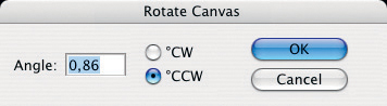
Figure 5-22: If you select Image ▸ Image Rotation ▸ Arbitrary, “Angle” will be preset to the value you have just measured using the ![]() tool.
tool.
For less critical flaws, you will have to decide whether it is quicker and more practical to correct them using individual image layers or in the final composite image. Birds sometimes appear as specks of dust in landscape panoramas, but can be easily removed using the clone stamp tool ![]() .
.
Perspective corrections are also best carried out after the images have been merged into a single layer, and the same applies to dodging or burning individual image areas. Adjustments to the alignment of your source images definitely need to be carried out before merging, and moving objects can also be more effectively removed from the source images than from the merged panorama.
For our completed image, as displayed in figure 5-24, there was hardly anything which needed to be corrected before merging. Although the source images were shot using an older, 5-megapixel camera, the final, cropped image nevertheless measured 6300 × 1400 pixels, which would print up to 21 × 4.7 inches when printed at 300 dpi (common for most ink jet printers).* The image proportions are not necessarily ideal, but are dictated by the subject.

Figure 5-23: The birds in this detail are bothersome because they are too small to really see. It is better to remove them completely using Clone Stamp tool.
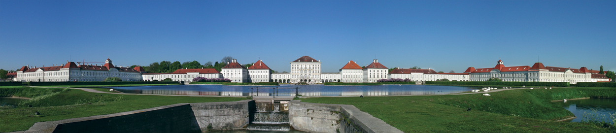
Figure 5-24: The aligned and cropped panorama with the birds over the central building removed.
Because this type of image is almost always viewed from a distance, printing a larger image with a lower resolution (200 dpi, for example) is also an option.
In figure 5-24 we have already dodged (brightened) several of the darker areas using a technique we’ll demonstrate later on. This is a correction we carried out after the individual layers had been merged into one.
Merging Layers
If you have plenty of hard drive space available, you can save the cropped image as a TIFF or PSD file with all the individual layers intact. As the steps we have taken so far are not too complicated or time-consuming (should you have to repeat them), you can also risk merging your layers into one and retouching the resulting single image. Layer merging is applied using the Layer ▸ Merge Visible command (which can be accessed more quickly using ![]() or
or ![]() ). For images consisting of large numbers of layers, this can significantly reduce the size of the resulting image file.
). For images consisting of large numbers of layers, this can significantly reduce the size of the resulting image file.
Dodging and Burning
In the image shown in figure 5-24, we removed birds from the sky over the central building and lightened up some of the darker areas after the layers were merged into one. We achieved this by creating a new layer (Layer ▸ New Layer) on top of the basis layer.
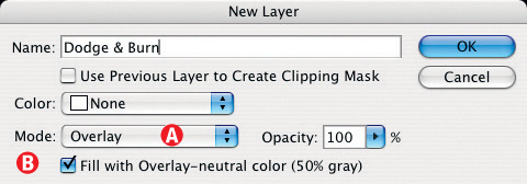
Figure 5-25: How to create an adjustment layer for dodging and burning.
In the New Layer dialog box, we set Mode ![]() to Overlay and activated option
to Overlay and activated option ![]() Fill with Overlay-neutral color for (50% gray) (see figure 5-25). We named this new layer “Dodge and Burn” and used it to selectively brighten or darken specific areas of our image. Here, we used the Paintbrush tool
Fill with Overlay-neutral color for (50% gray) (see figure 5-25). We named this new layer “Dodge and Burn” and used it to selectively brighten or darken specific areas of our image. Here, we used the Paintbrush tool ![]() set to a minimal degree of hardness (0–5%). We then used the color white to dodge (brighten) and black to burn where necessary. (The terms burning and dodging originated in conventional dark rooms, where these eponymous techniques were used to selectively correct exposures by hand.)
set to a minimal degree of hardness (0–5%). We then used the color white to dodge (brighten) and black to burn where necessary. (The terms burning and dodging originated in conventional dark rooms, where these eponymous techniques were used to selectively correct exposures by hand.)
Overlay mode works by leaving areas of 50% gray unchanged, while lighter areas are dodged (brightened) in degrees right up to pure white. In those areas where the adjustment layer is darker than 50% gray, a converse, burning (darkening) effect takes place, which is black at its strongest.
In order to retain control over the dodging and burning process, we use a low opacity value (10–20%) for our brush, and simply re-paint the areas which require a more marked effect. The brush size can be changed using the ![]() key to enlarge it and the
key to enlarge it and the ![]() key to shrink it. You can easily step backwards (undo) using the
key to shrink it. You can easily step backwards (undo) using the ![]() keystroke. In areas where you may have over-corrected, you can compensate by using a brush of the opposite color.
keystroke. In areas where you may have over-corrected, you can compensate by using a brush of the opposite color.
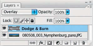
Figure 5-26: The layers of our dodged and burned panorama.
In the image in figure 5-24, we only dodged a little in order to brighten a couple of specific areas. Figure 5-27 shows our image before the adjustment and figure 5-28 afterwards. Figure 5-29 shows the brush strokes used in the adjustment layer. The results in the corrected image are subtle, but that is what we were aiming for.
This type of technique can be used to make similar corrections to many types of images, which is why we’ve addressed it so thoroughly. However, truly washed-out highlights and underexposed shadows cannot be corrected this way.
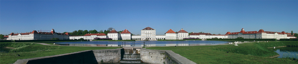
Figure 5-27: Image with birds removed from the sky before dodging.
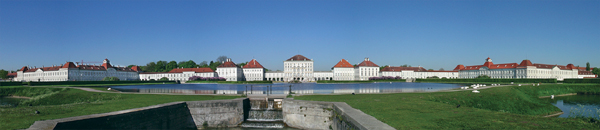
Figure 5-28: The dodged image – note the (formerly) darker surfaces of the buildings to the left and right of the central building.
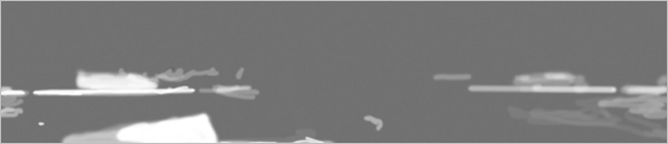
Figure 5-29: The adjustment layer used to dodge and burn the image shown in figure 5-28. The 50% gray areas have a neutral effect.
One thing which takes some getting used with this method is that – while Photoshop makes it possible to see corrections in the image window – the individual brush strokes are only visible in the (very) small thumbnail in the Layers palette. A workaround in this situation involves hiding all the other layers by holding down the ![]() -key and clicking the
-key and clicking the ![]() icon in the Layers palette.
icon in the Layers palette. ![]() -clicking the icon a second time shows all the layers again.
-clicking the icon a second time shows all the layers again.
Corrections Using the Clone Stamp Tool
Instead of simply cropping the “empty” areas around your merged image, you can also fill these with artificially generated details using the Photoshop Clone Stamp tool (![]() ). This process requires suitable material for cloning, which is not usually a problem for image areas containing grass, water, or pavement. Cloning simple cloud structures so that the results are not too obvious is also quite simple. The entire process becomes more complex and laborious once perspective plays a role, but Photoshop (CS2 and newer) once again has a solution.
). This process requires suitable material for cloning, which is not usually a problem for image areas containing grass, water, or pavement. Cloning simple cloud structures so that the results are not too obvious is also quite simple. The entire process becomes more complex and laborious once perspective plays a role, but Photoshop (CS2 and newer) once again has a solution.
Start by enlarging the canvas using the crop tool ![]() , then use the normal Stamp tool
, then use the normal Stamp tool ![]() to retouch the areas which do not require perspective correction. The Stamp process is conducted on a new, empty layer, with the Stamp tool’s options set to Current and Below (see figure 5-30).
to retouch the areas which do not require perspective correction. The Stamp process is conducted on a new, empty layer, with the Stamp tool’s options set to Current and Below (see figure 5-30).
Figure 5-30: The Clone Stamp tool settings.
Figure 5-31 shows a merged image compiled from nine source images taken using a tripod. Stitching and various adjustments have resulted in a good deal of empty space above and below the main image area. In order to avoid excessive cropping, we will first use the method described above to fill out the sky, and then the foreground – the latter with the help of the program’s Vanishing Point function. These are all corrections that are made once the image has been merged into a single layer.
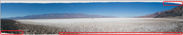
Figure 5-31: In this panorama, the area marked in red will be filled with detail using the Clone Stamp tool.
We now start filling in the sky in the upper right corner using the Clone Stamp tool ![]() .
.
The next step is to extend the sky upwards. First, we increase the canvas size using the top center handle in the crop ![]() frame. At this point, using the Stamp tool to fill the new space would be difficult, due to the fact that the sky gets darker towards the top. Instead, we select a strip of sky towards the top of the image which covers the entire width of the panorama using the Rectangle Marquee tool.
frame. At this point, using the Stamp tool to fill the new space would be difficult, due to the fact that the sky gets darker towards the top. Instead, we select a strip of sky towards the top of the image which covers the entire width of the panorama using the Rectangle Marquee tool.
Now we activate the Free Transform tool (Edit ▸ Free Transform) and drag the upper marquee handle all the way to the top of the canvas (see figure 5-34).
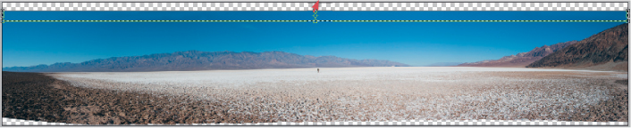
Figure 5-32: Dragging the center handle upwards with “Transform” activated stretches the selected area.
This stretches our selected area of sky to fill the rest of the canvas. The color gradient remains natural-looking and is simply stretched to fill the available space. To finish up, we cropped the remaining white space above the sky.
We perform our final correction – stamping in the foreground – using the Photoshop Vanishing Point function (Filter ▸ Vanishing Point). The function displays a dialog box like the one shown in figure 5-33, along with an image preview and a toolbar on the left of the image window.
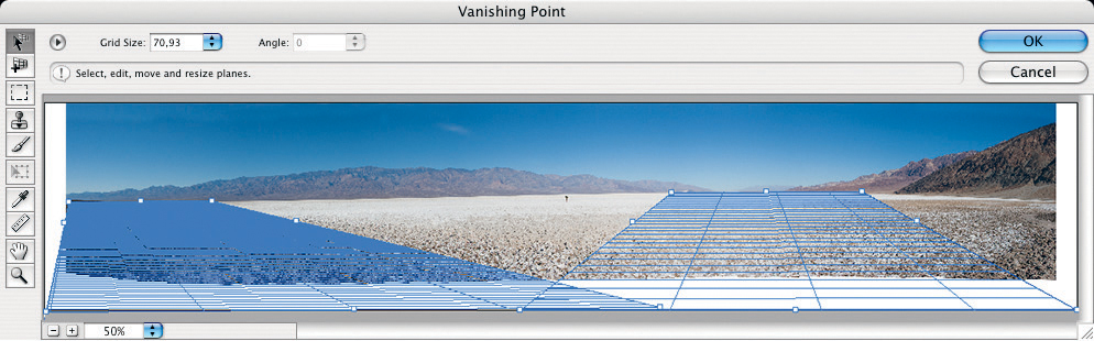
Figure 5-33: The vanishing point dialog window with two perspective planes already drawn.
Here, the first step involves defining the perspective planes using the Create Plane![]() tool, which is located at the top of the function’s toolbar (see figure 5-33). You can then use the mouse to position the four corners of the plane in counterclockwise order, starting at the front left. If necessary, multiple perspective planes can be created one after the other.
tool, which is located at the top of the function’s toolbar (see figure 5-33). You can then use the mouse to position the four corners of the plane in counterclockwise order, starting at the front left. If necessary, multiple perspective planes can be created one after the other.
Figure 5-33 shows the Vanishing Point dialog box with two perspective planes already drawn. You can adjust the corners of your perspective plane using the active Create Plane tool (![]() ), or using the
), or using the ![]() tool. Click on the plane you want to adjust and adjust the corner points at will. The concept of perspective planes and vanishing points can be quite complex, and can take a little getting used to.*
tool. Click on the plane you want to adjust and adjust the corner points at will. The concept of perspective planes and vanishing points can be quite complex, and can take a little getting used to.*
We now switch from using the Vanishing Point tool to using the Clone Stamp tool ![]() within the Vanishing Point dialog. Hold down the
within the Vanishing Point dialog. Hold down the ![]() key, click on the image area you wish to clone (as the source for your stamping), then simply paint using the stamp.
key, click on the image area you wish to clone (as the source for your stamping), then simply paint using the stamp.
If you’re used to working with the standard Clone Stamp tool, stamping on a perspective plane will feel strange at first. The reaction time will be slower, and the stamping action itself (i.e., the replacement of individual pixels) also behaves differently, due to the new perspective which has to be interpolated into the new pixels before they are mapped.
For the Clone Stamping process, we used a brush with 80% hardness, 90–100% opacity, and a very large diameter. If you are working with more than one perspective plane, you will have to activate each plane individually (by clicking ![]() and selecting the appropriate plane) in order to make corrections to it.
and selecting the appropriate plane) in order to make corrections to it.
As an alternative to the Stamp tool, you can also use the Selection tool ![]() to select rectangular areas for copying.* This creates a floating selection, that can then be moved (copied) to another area within the image, where it is transformed to match the perspective plane that is active in the new position.
to select rectangular areas for copying.* This creates a floating selection, that can then be moved (copied) to another area within the image, where it is transformed to match the perspective plane that is active in the new position.
Once we had made a number of stamp-based corrections and their associated changes to the perspective planes, we finally cropped the image and ended up with the result shown in figure 5-34. When using the stamp tool it is better not to clone sections which are too far towards the optical rear of a perspective plane, as the corresponding pixels will have been significantly distorted and enlarged, which can in turn lead to an unnecessary lack of sharpness and coarse textures.
If you are working with 16-bit images, you should only save your results to an 8-bit format at the very end of the process, once all your cloning and perspective corrections are complete. You can, of course, also stick with your 16-bit files if you have enough disk space.
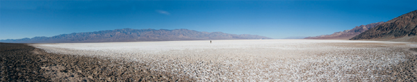
Figure 5-34: Here, the sky has been altered using the Clone Stamp, and the foreground has been enhanced using the Vanishing Point function.
Vertical Panoramas and Perspective Correction
In the example we just completed, we used Auto projection mode, which is usually accurate in its analysis of the source images and chooses Cylindrical or Perspective projection accordingly. The program uses some of the EXIF data stored within the source files to reach its decision, but the information concerning lens type and focal length will be missing from images that were either scanned or taken using older equipment which doesn’t transmit lens information to the camera. This can cause Photoshop problems when it is interpreting source images. Generally, Photoshop uses the central image of a panorama as its reference vanishing point, and distorts and shifts all other images around this central point.
In most cases, Photoshop can even detect which shots were taken using horizontal and which using vertical pans, and aligns them correctly, as can be seen in figures 5-35 and 5-36.
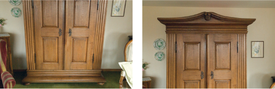
Figure 5-35: A typical shooting situation. Because of the small room and the 24 mm lens (plus a crop factor of 1.5), two shots were necessary to shoot the whole closet. The obvious noise in the image is the result of the high ISO speed setting (ISO 3200 shot using a Nikon D200).
Figure 5-36 shows the results we achieved using Photomerge set to Auto. The images were shot hand-held, and so had to be aligned before merging. We did this using the Ruler tool ![]() to draw a line along the edge of the closet. We then confirmed the automatically-calculated angle of rotation in the dialog Image ▸ Rotate Canvas ▸ Arbitrary.
to draw a line along the edge of the closet. We then confirmed the automatically-calculated angle of rotation in the dialog Image ▸ Rotate Canvas ▸ Arbitrary.
There is, however, still a noticeable degree of perspective distortion in the merged image, indicated by the three guidelines we have drawn through the image. You can create such guidelines simply by dragging the mouse from the rulers at the left or top edges of the image window.
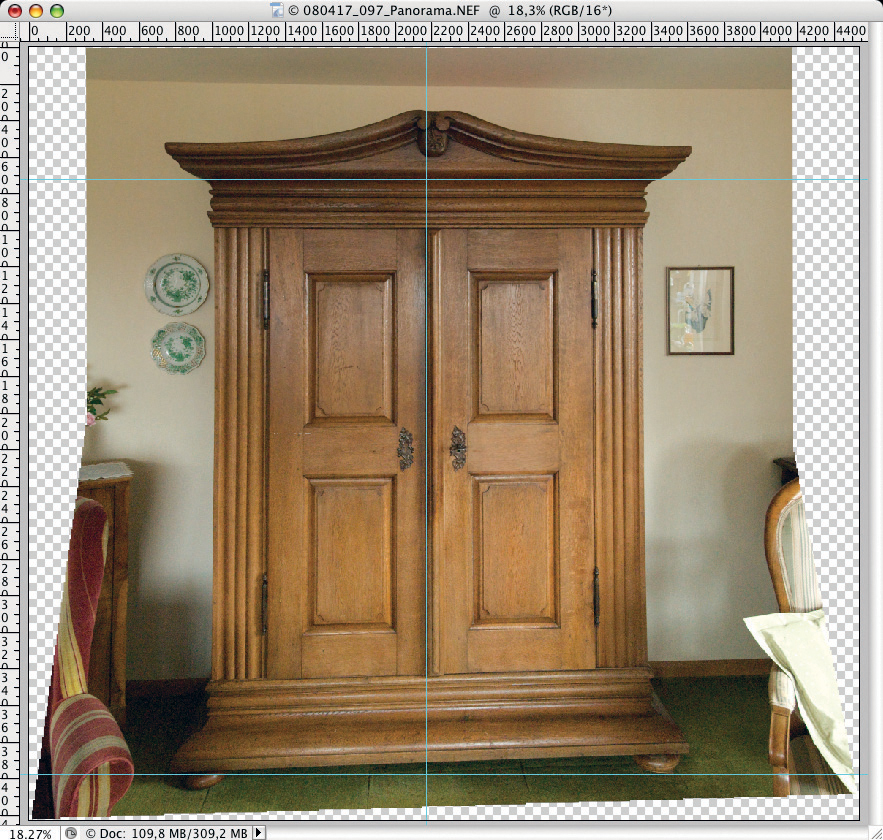
Figure 5-36: Result using Layout set to “Automatic”.
We then merge the individual layers into one, as previously described and move on to the lens correction stage (Filter ▸ Distort ▸ Lens Correction) shown in Figure 5-37. Here, we can adjust horizontal and vertical perspective, as well as correcting pin-cushion and barrel distortion.
For our example, we were able to restrict our processing to vertical and horizontal perspective corrections. Each redrawing of the preview image requires a fair amount of processing power, so make sure you move the sliders slowly, and wait for the preview image to complete before judging your results and making further corrections.
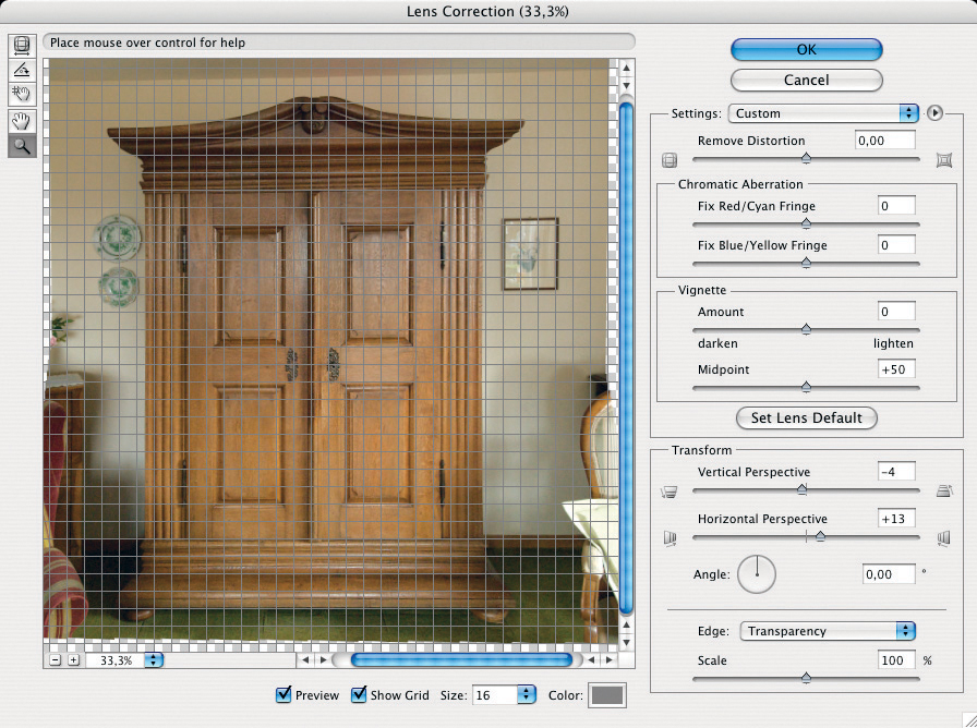
Figure 5-37: The “Lens Correction” filter can be used to manually correct perspective and lens distortions.
If you need to carry out a number of corrections, it is better to treat them as individual steps of a single process, and not to exit the Lens Correction filter dialog between individual corrections. If you exit the dialog after every step by clicking OK, the dialog is continually being restarted and interpolates the rounding errors involved in each new correction into the image data, causing creeping image quality loss.
If you have experience with the Photoshop Free Transform function you can often achieve faster results for simple examples, such as our closet. Free Transform cannot, however, be used to correct pincushion or barrel distortion. Figure 5-38 shows the corrected and cropped image of our closet.
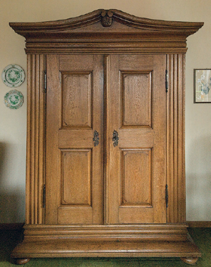
Figure 5-38: The final view of the closet after perspective correction and cropping.
Multi-Row Panoramas
Photoshop can also handle simple multi-row panoramas, as we will now demonstrate. For this example, we will be using source images of the famous Swieta Lipka church in Poland (see figure 5-39), again shot hand-held. In order to capture the height of the church, we had to use two rows of three images each.
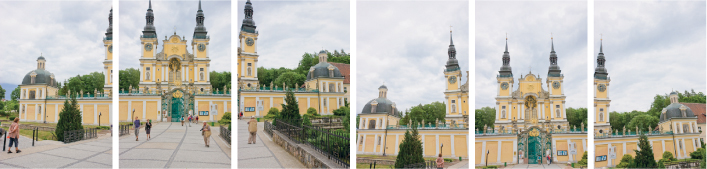
Figure 5-39: Six source images were shot hand-held in two rows, using a Canon 40D and a 21 mm lens (16 mm equivalent with a crop factor of 1.6).
In Photomerge, we chose Auto layout and ended up with the result shown in figure 5-41. Even using our fairly fast computer, Photoshop took its time to process the 10-megapixel images. Photomerge obviously used perspective projection, evident in the slanting lines visible at the edges of the image shown in figure 5-41. Because of the photographer’s low shooting position, pronounced perspective distortion is also clearly visible. Figure 5-40 shows the Layers palette with the masks created automatically by Photomerge.
For the purposes of analysis, it is interesting to see exactly which parts of each source image are used in the final image. Clicking on the eye icons next to the individual layers hides them temporarily, and often reveals astonishing results. Keep in mind, though, that Photoshop has at this point already aligned the source images and distorted them to match the chosen perspective layout.
In the case of moving objects (pedestrians in this example), Photomerge has done a pretty good job of automatically removing or matching them. An initial viewing reveals no obvious ghosting.
The next step is to merge the individual layers into one using ![]() or
or ![]() . We did not crop the image at this point, as we will be needing the surplus image area later to provide source material for our perspective corrections.
. We did not crop the image at this point, as we will be needing the surplus image area later to provide source material for our perspective corrections.
We now return to the Lens Correction filter and start by using the Straighten tool to align our image. We drag the ![]() tool along the front edge of the roof of the entrance building, creating an artificial horizon that the filter then uses to automatically rotate the image.
tool along the front edge of the roof of the entrance building, creating an artificial horizon that the filter then uses to automatically rotate the image.
The second step is to correct perspective. Here we will primarily be using the Vertical Perspective slider.
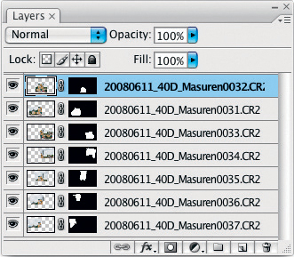
Figure 5-40: The Layers stack and layer masks created by Photomerge.
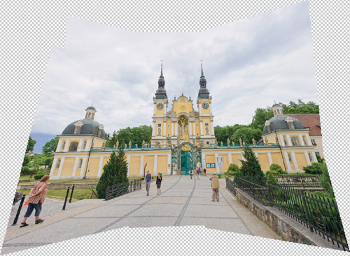
Figure 5-41: Our initial result using the “Perspective” layout shows distinct perspective distortion.
The substantial distortion our example shows requires us to use a high correction value of -96. Again, this type of correction is complex and will take time, even if you are using a powerful computer.
The next step is to correct horizontal perspective, this time using a much more modest value of +5. These settings are shown in figure 5-42. The two towers are still slightly too short, and are still slightly canted outwards. These are, however, not corrections we can address using the current dialog, so that is how our image remains for the time being.
Figure 5-43 shows our preliminary results. The image is still not ideal, but this is the best we can achieve using the methods described and the available image material.

Figure 5-42: The “Lens Correction” filter settings used to create figure 5-44.
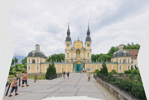
Figure 5-43: Results of perspective correction with the help of the “Lens Correction” filter.
Finally, we reduce our image to a single layer and crop it using the ![]() tool. Figure figure 5-44 shows the cropped image – we have deliberately left a large amount of sky at the top of the frame. There are now three remaining problems to be corrected: the pedestrian in the bottom far left corner of the image, the white space in the bottom right corner, and the church towers, which appear a little shorter than in reality, and which still appear to lean slightly outwards.
tool. Figure figure 5-44 shows the cropped image – we have deliberately left a large amount of sky at the top of the frame. There are now three remaining problems to be corrected: the pedestrian in the bottom far left corner of the image, the white space in the bottom right corner, and the church towers, which appear a little shorter than in reality, and which still appear to lean slightly outwards.

Figure 5-44: The cropped image. There are still several visible imperfections.
The white space near the bush at the bottom right can be simply corrected using the Clone Stamp tool. The pedestrian at the bottom left can also be removed (we hope she will forgive us!) using the stamp tool, although the process here is a little more complicated. In order to avoid having to use perspective planes, we will stamp almost exclusively horizontally. And, in order not to give ourselves away, we will remove the chain link fence too. As usual, we create a new, empty layer, and here, we activate the Current & below option in the Sample dialog (see figure 5-30 on page 116).
Correcting our leaning towers is more complicated. Here, we select an area around the star above the main gate using a fairly broad, soft edge, and leaving plenty of space on both sides. We then copy the selection using ![]() and paste it into a new layer using
and paste it into a new layer using ![]() . Figure 5-45 shows the resulting Layers palette.
. Figure 5-45 shows the resulting Layers palette.
We now use ![]() (or
(or ![]() ) to start the Free Transform tool in the new layer. First, we stretch our selection carefully upwards (see figure 5-46,
) to start the Free Transform tool in the new layer. First, we stretch our selection carefully upwards (see figure 5-46, ![]() ) to give the towers the appearance of more height. To retain realism, it is important not to overdo this type of stretch.
) to give the towers the appearance of more height. To retain realism, it is important not to overdo this type of stretch.
Now, we need to straighten the towers. We do this by clicking the top right-hand handle in the selection while holding down the ![]() or
or ![]() key (the cursor will take on the
key (the cursor will take on the ![]() -form), and dragging the handle slightly inwards until the right tower appears to be vertical
-form), and dragging the handle slightly inwards until the right tower appears to be vertical ![]() ). Figure 5-46 shows this transformation process.
). Figure 5-46 shows this transformation process.
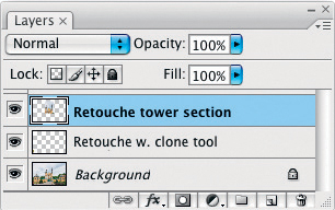
Figure 5-45: Our Layers palette after clone stamping and creation of a selection layer based around the church towers.
Again, we can use guidelines dragged out of the rulers to assist us. And remember that here too, Photoshop will need time to process each adjustment and to redraw the image preview. Pressing the enter key or double-clicking on the free transform area saves the current changes to the image file.

Figure 5-46: The tower detail during the Free Transform process.
The final step involves improving contrast and mid-tones using contrast and mid-tones using Curves. We will use the standard S-curve for our example (see figure 5-47)
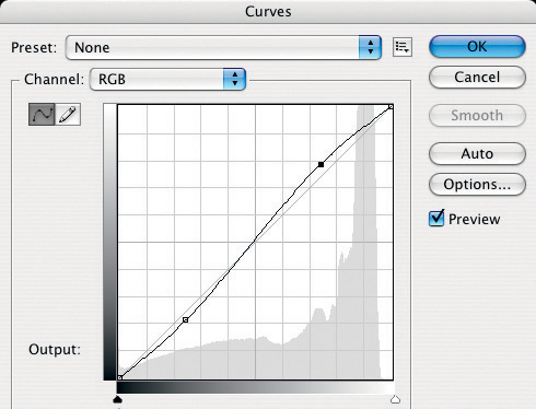
Figure 5-47: The Curves dialog showing the classic S-curve. This curve increases mid-tone contrast and, in most cases, color saturation.
We then improve microcontrast using the technique described in section 7.1. The DOP Detail Extractor will automatically generate a new layer that combines the layers beneath it and enhances detail contrast. Finally, we use the Photoshop Shadows/Highlights command to slightly dim the highlights and brighten the shadows.
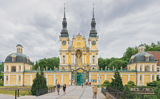
Figure 5-48: Our final image once all of the described corrections have been performed.
In order to improve the contrast of the sky, we create a Hue/Saturation adjustment layer, select the blue color channel, and select the sky’s blue hue using the eyedropper tool. We then increase saturation and decrease brightness, using a mask to prevent the building itself from being affected.
Now all we have to do is save our image, make a copy, and merge the individual layers into one. We then scale the image to our desired output size, adjusting the resolution if necessary. We then sharpen the resulting image to yield the result shown in figure 5-48.
Photoshop Photomerge Layout Modes
The previous examples have shown that Photoshop usually selects the appropriate projection type automatically if you use Auto layout mode. Sometimes, however, Photoshop evaluates a scene incorrectly, or you may explicitly want to use a different projection type. There are various ways of doing this: you can either set a specific projection type in the Photomerge dialog (see figure 5-49), which may require one or two attempts before you find the right choice; or you can select the Interactive Layout option. As of the CS3 version of the program, there is also a third option, called Reposition Only. This is a projection type used for panoramas which have been shot using parallel camera movements, rather than rotation – a technique that is usually used for panoramas that only encompass smaller numbers of images.
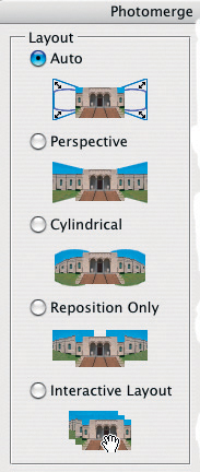
Figure 5-49: Photomerge offers several layouts (i.e., projection types).
A correct but easily comprehensible explanation of projection types is not easy to formulate. Harald Woeste addresses the topic extensively in his Rocky Nook book, Mastering Digital Panoramic Photography. Here is our (extremely simplified) explanation: If the total angle of view that you wish to cover with your panorama does not exceed 120°, you should use a Perspective projection. Some practitioners cite a maximum angle of view of 170°, but this is a number that appears to be based more on theory than practical usage. In a perspective projection, the horizontal and vertical lines in the center of the panorama image remain mostly unaffected, while the lines in the surrounding areas become increasingly distorted to fit the overall view – and the more extreme the angle of view, the more extreme the distortion will be. In the case of total angles of view of more than 120°, you should really use a Cylindrical projection.
The types of manual perspective adjustments we have had to make in our examples are generally caused by the shooting angles for the source images, and not by the actual stitching process. Photoshop cannot automatically compensate for a tilted camera. Some other stitching programs support this type of correction, although they require additional input regarding the angles of tilt involved in order to function correctly.
We will now go into some more detail concerning the Photoshop Interactive layout type. Our source images for this example are shown in figure 5-50. They were taken using a compact camera with an effective (35 mm format) focal length of 37 mm. This represents a horizontal angle of view of about 53° per shot, which definitely adds up to more than the recommended 120° upper limit for perspective projection panoramas.
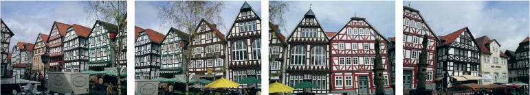
Figure 5-50: Our four source images, taken hand-held at the old market square in Fritzlar, Germany.
Start the Photomerge function and select the Interactive Layout option to display the dialog shown in figure 5-51. Although everything looks fine at first glance, a closer look reveals some scruffy-looking overlaps and a fair amount of distortion. Many of these problems can be remedied interactively.
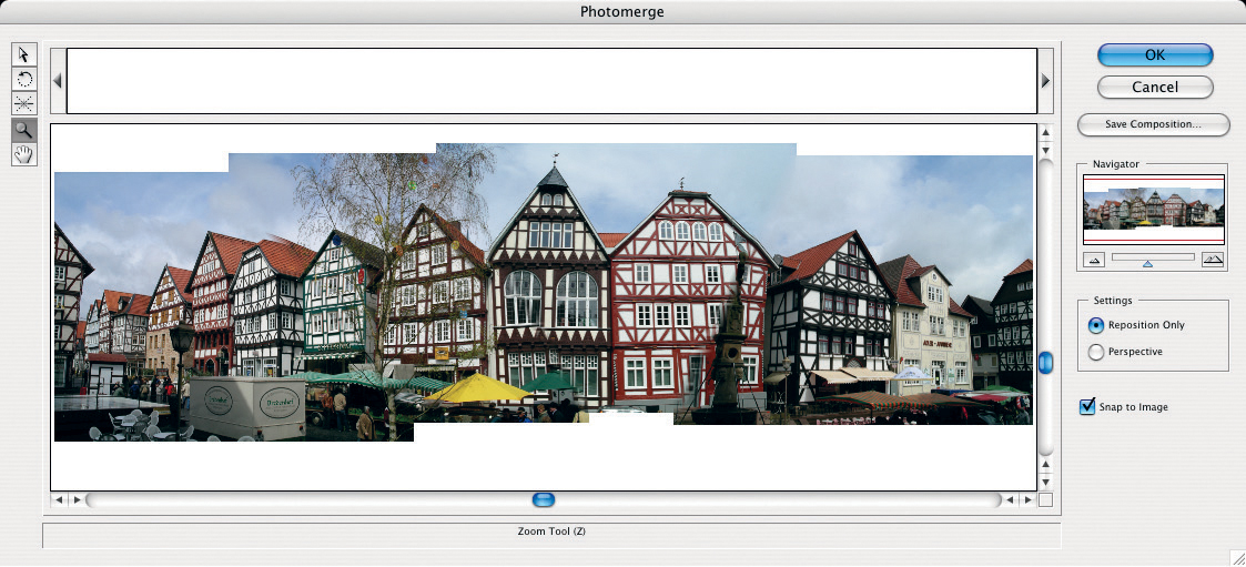
Figure 5-51: The Photomerge dialog as it appears when “Interactive Layout” is selected.
Figure 5-52: The five tools available in the Photomerge interactive layout.
Before we continue, here is a quick description of the tools available in the dialog shown above (see also the magnified view in figure 5-52). At the bottom right in the Settings box, we see that the Reposition Only option is activated, which generally leads to bad results. Choosing the Perspective option will improve things immediately, as can be seen in figure 5-53. We now have obvious distortion at the left end of the image, as the angle of view is too large for this type of projection, and the vanishing point has not been well-chosen.
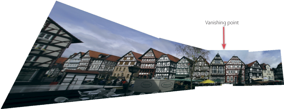
Figure 5-53: Our image after activating the “Perspective” option. The distortion to the left results from the asymmetrical vanishing point and the very large angle of view.
We can use the ![]() tool to drag individual images from the panorama onto the lightbox area of the dialog box or vice versa. If you use the
tool to drag individual images from the panorama onto the lightbox area of the dialog box or vice versa. If you use the ![]() tool to click on a particular image area, the corresponding layer will be activated and that portion of the image selected. You can then use the mouse to shift that part of the image within the panorama. You can position your selection even more precisely using the arrow keys on the keyboard.
tool to click on a particular image area, the corresponding layer will be activated and that portion of the image selected. You can then use the mouse to shift that part of the image within the panorama. You can position your selection even more precisely using the arrow keys on the keyboard.
The Vanishing Point tool ![]() is self-explanatory, and is used to select the source image that Photoshop should use as its vanishing point reference. (It is only available when using Perspective layout.) The program will then arrange the other source images correspondingly to the left and right of this image. The Vanishing Point tool can only be used when the projection type is set to Perspective.
is self-explanatory, and is used to select the source image that Photoshop should use as its vanishing point reference. (It is only available when using Perspective layout.) The program will then arrange the other source images correspondingly to the left and right of this image. The Vanishing Point tool can only be used when the projection type is set to Perspective.
The ![]() tool allows you to rotate individual images. The zoom tool
tool allows you to rotate individual images. The zoom tool ![]() allows you to zoom in (and out while holding down the
allows you to zoom in (and out while holding down the ![]() key), and the hand tool
key), and the hand tool ![]() allows you to shift the visible detail within the window using the mouse. This can be helpful if you have zoomed in so far that the entire image cannot be displayed at once.
allows you to shift the visible detail within the window using the mouse. This can be helpful if you have zoomed in so far that the entire image cannot be displayed at once.
As is the case with other complex operations, you will here also need to work slowly to give Photoshop time to update the preview.
Complex panoramas can take quite a while to perfect. For this reason, Photoshop offers the Save Composition button, which saves the current settings and associates them with the appropriate source images in a project file with the “.pmg”* ending. You can then load this file later to resume working exactly where you left off.
The CS4 version of Photoshop has added three additional layouts (projection types): Spherical (as described on page 109), Collage, and Reposition. Interactive Layout is no longer available as an option.
5.5 Bringing People Together – Group Panoramas
Photomerge’s ability to analyze and group images is so sophisticated, that it can recognize individual faces and merge them intelligently. We shall demonstrate this functionality using source images of a family gathering.
Our group was large and broadly spread out – i.e., perfect panorama material. We could have simply used an ultra-wide-angle lens to take our photo, but this would definitely have led to the kind of distortion that is disadvantageous in portraits. We could also have simply stood further back, but this would have led to excessively large border areas in the final photo, which we would have had to crop, in turn leading to a reduction in image resolution. The results would have sufficed for a 4 × 6 inch or 8 × 10 inch print (the source images were taken with a Nikon D200), but not for a larger, high-quality print.
So, is it possible to create a usable panorama using source images in which people are continuously changing positions?
Thanks to Photoshop (CS3 and higher), it is. We haven’t by the way, tested this functionality using older versions of the program.
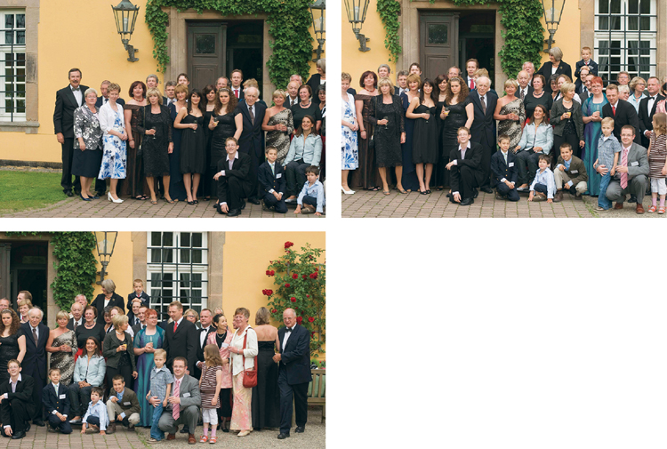
Figure 5-54: The three source images for our family stitching.
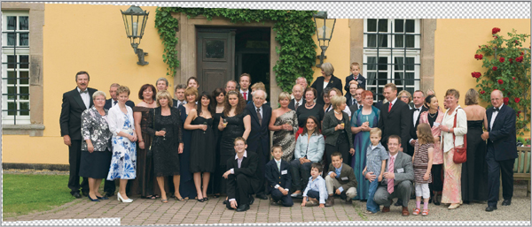
Figure 5-55: The initial result of using Photomerge to stitch our family together.
We loaded our source images into Photomerge via Photoshop as described earlier without any further preparation. We then merged our images using the Auto option, and the result can be seen in figure 5-55.
In order to avoid having to crop too closely in our final panorama, we used the Clone Stamp tool to add in some extra cobble stones in the foreground. We also straightened the image, applied a little perspective correction, cropped, and then used Shadows/Highlights to add texture to the dark suits and bright jackets. We also sharpened the entire image using the Unsharp Mask (USM) filter. The final result can be seen in figure 5-56. The image measures 6,050 × 2,650 pixels and can be successfully printed at up to 20 × 9 inches (at 300 ppi). Because this type of image is often viewed from a slight distance, it would also be possible to get away with a slightly larger print (28 × 12 inches, for example) printed at 220 dpi.
USM is the “Unsharp Mask” filter of Photoshop.
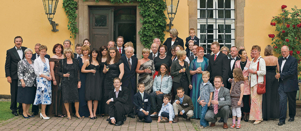
Figure 5-56: The final picture has been slightly corrected with a stamp tool, cropped, perspective adjusted, and sharpened.
5.6 Other Stitching Programs
Photoshop is a great program for basic stitching applications, and its functionality is expanded with every new version release. For more complex processes, however, it lacks a number of subtleties and extensions which are available in other programs. Specialized programs offer more sophisticated functionality including:
![]() A useful and easily accessible web site dealing with panorama photography in general can be found at www.panoramas.dk/panorama/software.html.
A useful and easily accessible web site dealing with panorama photography in general can be found at www.panoramas.dk/panorama/software.html.
To some extent, Photoshop CS4 also offers profile-based correction of vignetting and geometric (lens) distortion.
▸ Profile-based corrections to lens errors (distortion, aberration, and vignetting)
▸ The option of setting fixed coverage points in individual images. These fixed points will later be used to coordinate overlap in the stitched image, allowing more precise stitching. This can be useful for applications where straight lines are critical, such as for architectural photography.
▸ Extended perspective distortion correction
▸ Creation of 360° panoramas. While Photoshop is capable of creating 360° cylinder panoramas, it is still not capable of ensuring a smooth transition between the first and last image of a 360° stack.
▸ Creation of spherical panoramas (Photoshop CS4 also supports this) and other projection types, such as the Mercator* projection.
![]() Since Photoshop CS4 this feature is also available in Photoshop.
Since Photoshop CS4 this feature is also available in Photoshop.
QTVR stands for “QuickTime Virtual Reality”
▸ Export to various panorama formats, which can then be viewed using specialized panoramic viewing software. One example is the QTVR, format, which allows you to take virtual tours, and to zoom in and out of panorama images. There are many more formats available for online viewing of panoramas.
▸ Better support for multi-row panoramas. 360° panoramas are almost always multi-row panoramas. Since the CS3 version, Photoshop also has adequate multi-row panorama support for panoramas which are not too wide.**
▸ Support for fish-eye lenses and fish-eye lens distortion correction (also supported by Photoshop CS4)
▸ Batch processing of images in a panorama sequence
▸ While Photoshop isn’t capable of working with 32-bit HDR images, some other stitching programs are. These include Hugin and Stitcher Unlimited by REALVIZ.
▸ Hotspot support. These are “live” points within a panorama which produce an action when clicked. Hotspots function in a similar way to HTML links.
Currently available panorama software ranges from simple, easy-to-use programs (usually included for free with the purchase of a new digital camera) to very powerful and sometimes very expensive specialist program suites. Please note, however, that powerful doesn’t always imply expensive.
One such powerful freeware tool is PanoTools. This program was originally developed by Professor Helmut Dersch, and remains in continual development as an open source project at [30].* Because PanoTools is a command-line-based program, a number of graphical front ends have been developed to simplify its use. Such graphical interfaces either run the program’s commands in the background, or start each command manually in sequence. These command-based tasks include establishing overlap points, correcting perspectives, general image optimization, creating overlay masks, and much more besides.
The program’s multifarious capabilities are simultaneously a strength and a weakness, as the program assumes that all the individual modules are installed correctly, and that they are up to date. This is necessary if the program is to successfully pass individual module parameters to the computer’s operating system, or for potential error messages to be correctly interpreted. Additionally, some of the program’s modules can be called by various different sub-routines, which can make using the program confusing.
One of the better freeware variants is Hugin [29]. Commercial programs such as PTMac, Calio (both by Kekus [31]), or PTGui [32] are available for prices of around $40 to $120 per module. Some of the programs listed have moved away from the PanoTools base and now use their own modules and algorithms.
HDRI Panoramas
In the case of very wide panoramas, including 360° and spherical projections, the dynamic range of the entire image is usually greater than can be captured by the camera using a single exposure setting. The same is also true for panoramas shot indoors or at night. These types of situations are therefore ideally suited for enhancement using HDRI techniques. To create HDRI panoramas, you need to make multiple exposures of each part of your scene using different exposure values. You can then build your panorama using one of two basic methods:
A. Source images with the same exposure values are merged to make multiple panorama images. These “source panoramas” are then merged together into a single HDRI panorama.
The advantage of this method is that it can be applied using almost all stitching programs, including Photoshop. The disadvantage is that the stitcher may have difficulty automatically finding control points in images which are over- or underexposed. Additionally, the automatic brightness balancing which is often applied to panoramas can cause problems when merging differently-exposed panoramas into a single HDR image.
B. Alternatively, you can merge each of the different exposures of one part of your scene into separate HDRI source images, and then stitch them to create a single HDRI panorama. If you want to use this technique, you need to make sure your stitcher supports the stitching of HDR images.
In both cases, the initial result will be an extremely large image file. You will definitely need a powerful computer, lots of RAM, and patience if you want to experiment with this type of technique.
If the tonal range of your scene is not too broad, and you do not necessarily want to produce a typical HDRI look in your final image, there is another alternative method you can use to create your panorama. Simply process your individual source images using DRI or HDRI tools, tone map your images at 8-bit or 16-bit color depth, and then merge them into a panorama. This method avoids the final tone mapping stage, and allows you to stitch images with a program that doesn’t support HDRI. The PhotoAcute HDRI function is a good option for this type of process, and produces 8-bit or 16-bit LDR* images.
Further Information
This has been a relatively simple introduction to the problems – or better, challenges – associated with stitching techniques. There is a wealth of additional information available online, and we have already mentioned [53] and [58] as starting points. Once you have decided which stitching program you want to use, it makes sense to search for information relating only to that program, as many online solutions are highly program-specific.
Before you go out and spend money on specialized panorama equipment, you should gather experience shooting and stitching simple panoramas. This way, you can learn a lot that can help you later in a variety of contexts, not just in relation to panorama shoots. Basic stitching techniques can be useful in many other situations, and should be part of every photographer’s repertoire. Photoshop is a thoroughly serviceable entry point to panorama processing, although if you are prepared to spend a day or two on a fairly steep learning curve, the free, powerful, but complex Hugin [29] has a lot to offer. For a small investment, you can get to grips with PTGui [32], PTMac [31], or Stitcher Unlimited by REALVIZ [34]. Another alternative is Autopano Pro by Kolor [33], which is very simple to use but nevertheless allows a fair degree of customization. Most of these programs are available for Windows and Mac OS X, and some are even available for Linux. Again, the appropriate forums are the best source of up-to-date information relating to all the programs mentioned.**
The CS4 version of Photoshop has introduced a number of improvements, including spherical panorama layouts, as well as automatic vignetting and geometric distortion correction (see figure 5-57). Only the Interactive Layout function described on pages 125 to 127 is no longer available in the latest version.
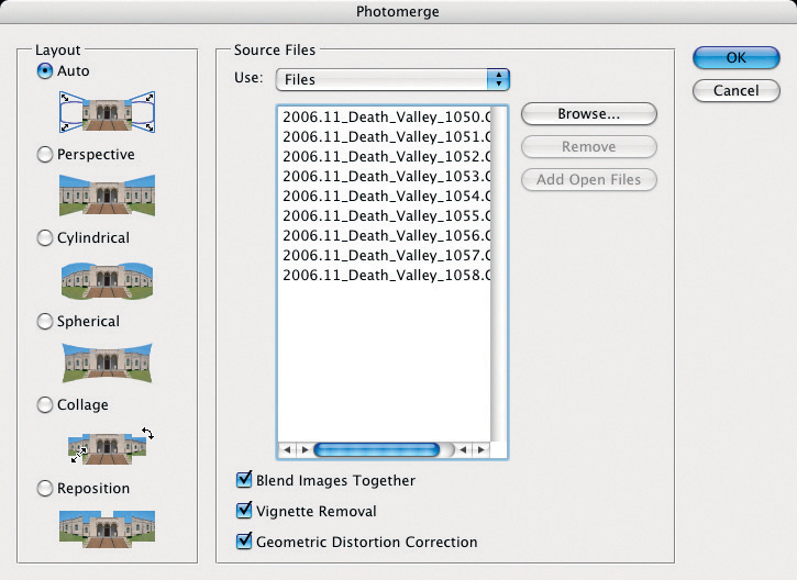
Figure 5-57: Photomerge in Photoshop CS4 offers a number of additional layouts (projection types) and automatic correction of vignetting and geometric distortion.
Photoshop CS4 also offers a new way to stitch images without using Photomerge:
1. Load your source images using File ▸ Scripts ▸ Load Files into Stack. Do not activate the option Attempt to Automatically Align Source Images.
2. Select all images in the Layers palette and use Edit ▸ Auto-Align Layers. This will call up the dialog shown in figure 5-58 (which is almost identical to the dialog shown in figure 5-57). Here, you should select either Auto or your desired layout.
3. Finally, with all layers selected, use the Edit ▸ Auto-Blend Layers command. This will display the dialog shown in in figure 5-59. Activate the Panorama option and check the Seamless Tones and Colors check box, and then click OK. Photoshop will then blend your images while retaining all the individual layers.
We cannot cover all the new layout types offered by Photoshop CS4 in detail here, but it is well worth trying them out, especially as some of them (Spherical, for example) can be combined with the new 3D functions that are included in the “Extended” version of CS4.
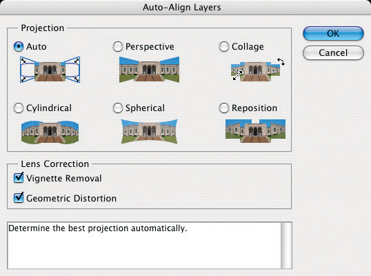
Figure 5-58: The Auto-Align Layers dialog.