
Symmetrical Components for Power System Analysis
Altran Solutions
2.2 Discussion of Per Unit Quantities
2.5 Phase and Sequence Relationships
2.6 Positive Sequence Networks
2.7 Sample Three-Phase Fault Calculation: Fault at Bus T2H
2.8 Sample Three-Phase Fault Calculation: Fault at Bus T2L
2.9 Negative Sequence Networks
2.10 Sample Phase to Phase Fault Calculation: Fault at Bus T2L
2.12 Sample Phase to Ground Fault Calculation: Fault at Bus T2L
Three-phase power systems are difficult to model and analyze using traditional methods, that is, using loop equations (Kirchoff’s laws) and node equations (Norton’s laws) when transformer turns ratios and transformer winding connections are included in the calculations. In this chapter, an alternate approach using “symmetrical components” will be introduced. The concept was first proposed by C.L. Fortescue in 1918 in a classic paper devoted to consideration of the general N-phase case.
Per phase analysis can be developed for the simple three-phase system illustrated in Figure 2.1 by solving Equations 2.1a through 2.1d. After line and residual currents are calculated, voltage can be calculated:
(2.1a) |
(2.1b) |
(2.1c) |
(2.1d) |
Solving Equations 2.1 is tedious because all values are vectorial, that is, voltages are represented as a voltage magnitude with an associated angle and impedances are represented as complex impedances that include resistance and reactance components. In addition, the residual system impedance (ZR) is the parallel combination of neutral and earth impedance.

FIGURE 2.1 General three-phase circuit.
Using symmetrical components, analysis is greatly simplified because calculations are a function of load or fault condition rather than a function of source voltage. Conversion from phase quantities to symmetrical quantities or from symmetrical quantities to phase quantities is easily accomplished using rules established by Dr. Fortescue. The basic premise underlying symmetrical components is that calculations, for any load or fault condition, can be developed using single phase methods. Figures 2.2 through 2.5 illustrate impedance networks used to calculate three-phase faults, phase to phase faults, single phase to ground faults, and double phase to ground faults.
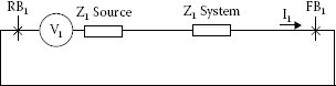
FIGURE 2.2 Three-phase fault—symmetrical component equivalent circuit.

FIGURE 2.3 Phase to phase fault—symmetrical component equivalent circuit.

FIGURE 2.4 Single phase to ground fault—symmetrical component equivalent circuit.
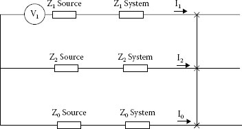
FIGURE 2.5 Double phase to ground fault—symmetrical component equivalent circuit.
Generally, two simplifying assumptions are made, namely, source voltages and system impedances are balanced. Although symmetrical components can be used to develop calculations for unbalanced source voltages and/or unbalanced system impedances, such calculations are beyond the scope of this book.
2.2 Discussion of Per Unit Quantities
Calculations are developed using per unit quantities for voltage, current, and impedance as per unit quantities eliminate the need to use transformer turns ratios and conversions throughout calculations. The use of per unit quantities, however, introduces the need to convert all impedances to a common MVA base before developing calculations and the need to convert per unit quantities to volts and amps after calculations have been developed.
Common practice is to develop calculations using nominal system voltages as base voltages. Calculations with transformers operating with off-nominal tap positions are only developed when special considerations arise.
Transformer impedances, which are listed in percent on transformer nameplates, are determined by test during factory acceptance tests. Per unit values are equal to percent values divided by 100. Transformer winding connections need to be included as essential system data.
Generator impedances, which are listed on data sheets in per unit quantities, are a function of fault duration. For short circuit analysis, (generator subtransient reactance) is used. (generator transient reactance a few cycles after a three-phase fault occurs on the terminals of a generator) and Xd (generator synchronous reactance when a three-phase fault persists on the terminals of a generator) are used when developing specific calculations to analyze generator parameters, generating station circuit breaker interrupting capability, stuck circuit breaker conditions at generating stations, etc.
Line (feeder or circuit) impedances are a function of conductor length, size, type, spacing, phase relationship, construction, bundling, etc., are application specific, and need to be calculated for each specific line. (In many applications, standardized line impedances are available and the calculation becomes a function of line length only.)
Motor impedance is a function of the condition being analyzed—running, starting, or backfeeding a fault. The duration of motor backfeed is a function of inertia of the driven load. When specific motor data is not available, a common practice is to assume running power factor is 85%, starting power factor is 30%, and motor impedance during backfeed conditions is 0.10 per unit.
When developing calculations using per unit quantities, any MVA base can be used. Common practice is to use 1 MVA as the base for low-voltage systems, 10 MVA for medium voltage systems, and 100 MVA for high-voltage systems. After base MVA and base voltage are selected, base amps and base ohms are calculated using the Equations 2.2a and 2.2b for three-phase systems and Equations 2.3a and 2.3b for single phase systems:
(2.2a) |
(2.2b) |
(2.3a) |
(2.3b) |
Calculated values for base amps and base ohms, when base MVA and base voltage are selected, are shown in Table 2.1.
Per unit impedances for components are converted from nameplate values to base values using Equations 2.4a and 2.4b:
(2.4a) |
(2.4b) |
Table 2.2 Lists per unit impedances that are converted from given MVA to base MVA.
Table 2.3 Lists per unit impedance that are converted from given kV to base kV.
Base MVA (MVA) |
Base Voltage |
Base Amps (A) |
Base Ohms (Ω) |
1 |
120 V, 1φ |
8333 |
0.014 |
1 |
277 V, 1φ |
3610 |
0.077 |
1 |
208 V, 3φ |
2775 |
0.043 |
1 |
480 V, 3φ |
1202 |
0.230 |
10 |
12.47 kV, 3φ |
463 |
15.55 |
10 |
13.8 kV, 3φ |
418 |
19.0 |
10 |
34.5 V, 3φ |
167 |
119 |
100 |
69 kV, 3φ |
837 |
47.6 |
100 |
138 kV, 3φ |
418 |
190 |
100 |
230 kV, 3φ |
251 |
529 |
100 |
345 kV, 3φ |
167 |
1190 |
100 |
500 kV, 3φ |
115 |
2500 |
TABLE 2.2 Impedance Conversion to Common MVA Base
Given MVA (MVA) |
Base MVA (MVA) |
Given Impedance (%) |
Impedance at Base MVA (%) |
0.25 |
1 |
1 |
4.00 |
0.5 |
1 |
1 |
2.00 |
1.0 |
1 |
1 |
1.00 |
2.0 |
1 |
1 |
0.50 |
2.5 |
10 |
5 |
20.00 |
5.0 |
10 |
5 |
10.00 |
10 |
10 |
5 |
5.00 |
20 |
10 |
5 |
2.50 |
25 |
100 |
10 |
40.00 |
50 |
100 |
10 |
20.00 |
100 |
100 |
10 |
10.00 |
200 |
100 |
10 |
5.00 |
TABLE 2.3 Impedance Conversion to Common Voltage Base
Given kV (kV) |
Base kV (kV) |
Given Impedance (%) |
Impedance at Base kV (%) |
13.2 |
13.8 |
5 |
4.57 |
13.8 |
13.8 |
5 |
5.00 |
14.1 |
13.8 |
5 |
5.22 |
220 |
230 |
10 |
9.15 |
230 |
230 |
10 |
10.00 |
245 |
230 |
10 |
11.35 |
Per unit values can be converted to actual values using the following equations:
(2.5a) |
(2.5b) |
(2.5c) |
Impedance conversions to common voltage and MVA bases are necessary when transformers with different voltage ratings, but similar turns ratios, are connected in parallel. This is illustrated in Table 2.4.
TABLE 2.4 Transformer Data Converted to Common Base
Transformer 1 |
Data |
Transformer 2 Data |
|
25 |
MVA |
25 |
MVA |
69 |
kV |
66 |
kV |
13.2 |
kV |
12.47 |
kV |
7% |
Impedance |
7% |
Impedance |
5.227 |
Transformer turns ratio |
5.293 |
Transformer turns ratio |
190.44 |
Base ohms, 25 MVA, 69 kV |
174.24 |
Base ohms, 25 MVA, 66 kV |
13.33 |
Transformer ohms |
12.20 |
Transformer ohms |
28.0% |
At 100 MVA, 69 kV |
25.6% |
At 100 MVA, 69 kV |
The fundamental principles of symmetrical components are as follows:
1. Single phase methods can be used to solve problems on three-phase systems.
2. Sequence networks have been developed to calculate sequence voltages and sequence currents. These networks are designated the positive sequence network, the negative sequence network, and the zero sequence network.
3. Each sequence has its own line conductors, transformer equivalent circuits, generator equivalent circuits, etc.
4. Each sequence is independent of the other sequences (for balanced fault conditions).
5. Per unit quantities are used in calculations.
6. Single phase to ground faults are calculated as Aφ to ground faults.
7. Phase to phase faults are calculated as Bφ to Cφ faults.
8. Sequence currents are calculated at a fault bus. Current dividers are used to calculate sequence currents at other points in each sequence network.
9. Sequence voltages are calculated at a fault bus. Voltage dividers are used to calculate sequence voltages at other points in each sequence network.
10. Positive sequence voltage is maximum at a generator and minimum at a fault bus.
11. Negative sequence voltage is maximum at a fault bus and zero at the reference bus.
12. Zero sequence voltage is maximum at a fault bus and zero at the reference bus.
13. Phase voltage can be calculated when sequence voltages are known.
14. Phase current can be calculated when sequence currents are known.
15. Sequence voltages can be calculated if phase voltages are known.
16. Sequence currents can be calculated if phase currents are known.
Symmetrical components utilize a unit vector, designated “a,” to transform phase quantities to sequence quantities and to transform sequence quantities to phase quantities.
The properties of the “a” vector are as follows:
(2.6a) |
(2.6b) |
(2.6c) |
(2.6d) |
(2.6e) |
(2.6f) |
(2.6g) |
2.5 Phase and Sequence Relationships
Power system voltages and currents are represented as the sum of sequence values:
(2.7a) |
(2.7b) |
(2.7c) |
(2.8a) |
(2.8b) |
(2.8c) |
Sequence values are derived from phase voltages and current using the following:
(2.9a) |
(2.9b) |
(2.9c) |
(2.10a) |
(2.10b) |
(2.10c) |
Positive sequence voltages and currents are represented by vectors that have equal amplitudes and are displaced 120° relative to each other as shown in Figure 2.6:
(2.11a) |
(2.11b) |
(2.11c) |
(2.12a) |
(2.12b) |
(2.12c) |

FIGURE 2.6 Positive sequence voltage vectors.
Negative sequence voltages and currents are represented by vectors that have equal amplitudes and are displaced 120° relative to each other, as shown in Figure 2.7. The rotation of the negative sequence vectors is opposite the rotation of the positive sequence vectors:
(2.13a) |
(2.13b) |
(2.13c) |
(2.14a) |
(2.14b) |
(2.14c) |
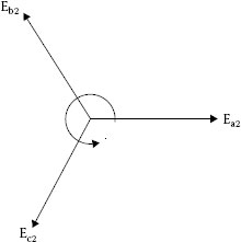
FIGURE 2.7 Negative sequence voltage vectors.

FIGURE 2.8 Zero sequence voltage vectors.
Zero sequence voltages and currents are represented by vectors that have equal amplitudes that are in phase with each other, as shown in Figure 2.8:
(2.15a) |
(2.15b) |
(2.15c) |
(2.16a) |
(2.16b) |
(2.16c) |
When calculations are developed, sequence quantities, that is, Ia0, Ia1, Ia2 and Ea0, Ea1, Ea2, are calculated. Then, phase quantities are calculated using previous equations.
The use of symmetrical components and the determination of the magnitude and angle of positive sequence, negative sequence, and zero sequence vectors for various fault conditions will be demonstrated for the power system shown in Figure 2.9. This power system consists of a generator, two transformers, and one transmission line. For this generator X/R = 40 and for these transformers X/R = 25. When X/R is 10 or less, resistance is generally included in calculations.
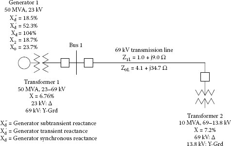
FIGURE 2.9 Power system single line diagram.

FIGURE 2.10 Positive sequence network for power system shown in Figure 2.9.

FIGURE 2.11 Positive sequence network with normalized impedances.
2.6 Positive Sequence Networks
Positive sequence networks are in all respects identical to the usual single line diagram for three-phase networks. The resistances and reactances are the values used in traditional equivalent circuits. Although each machine (generator or motor) is considered to be a voltage (power) source, motors are omitted when fault contributions from motors are negligible.
Figure 2.10 is the positive sequence network for the system shown in Figure 2.9. The positive sequence reference bus, RB1, the common point to which all power sources are connected, is needed for network analysis. Other buses shown in Figure 2.10 (G1, 1, T2H and T2L) are locations where faults can be analyzed by inserting a jumper from a fault bus (G1, 1, T2H or T2L), to a reference bus, RB1. Positive sequence jumper connections vary with fault type as shown in Figures 2.2 through 2.5.
Figure 2.11 is the positive sequence network with normalized impedances. To calculate a three-phase fault, a jumper is placed between RB1 and the fault bus.
2.7 Sample Three-Phase Fault Calculation: Fault at Bus T2H
2.8 Sample three-Phase Fault Calculation: Fault at Bus T2L
2.9 Negative Sequence Networks
Negative sequence networks are similar to positive sequence networks in that the number of branches is the same. But, negative sequence networks do not contain voltage sources because machines (generators or motors) only generate positive sequence voltage. The other difference between negative sequence networks and positive sequence networks is that different machine impedances may be used in each sequence. For most calculations, machine negative sequence impedance is assumed to be equal to positive sequence impedance. Different positive sequence and negative sequence impedances are used when generator response to short circuit conditions or circuit breaker interrupting capabilities are being evaluated at generating stations.
Figure 2.12 is the negative sequence network for the system shown in Figure 2.9. The negative sequence reference bus, RB2, the common point to which all power sources are connected, is needed for network analysis. Other buses shown in Figure 2.12 (G1, 1, T2H and T2L) are locations where faults can be analyzed by inserting a jumper from a fault bus to a reference bus. Negative sequence jumper connections vary with fault type, as shown in Figures 2.3 through 2.5.
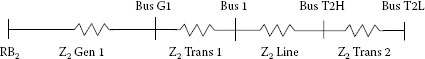
FIGURE 2.12 Negative sequence network for power system shown in Figure 2.9.

FIGURE 2.13 Negative sequence network with normalized impedances.
Figure 2.13 is the negative sequence network with normalized impedances. To calculate a phase to phase fault, the positive and negative sequence networks must be connected, as shown in Figure 2.3. This means that one jumper is needed between RB1 and RB2 and a second jumper is needed between the positive sequence fault bus and the corresponding negative sequence fault bus.
2.10 Sample Phase to Phase Fault Calculation: Fault at Bus T2L
Zero sequence networks, like negative sequence networks, do not contain voltage sources because machines (generators or motors) only generate positive sequence voltages. However, the number and connection of branches will be strongly influenced by transformer winding connections. Most zero sequence networks consist of an array of separate zero sequence networks, as shown in Figure 2.14.
Zero sequence line impedances are obtained by imagining three conductors connected together at the point of fault with the ground forming the return conductor.
Checking transformer winding connections, and properly accounting for them in zero sequence networks, is a necessary requirement when calculating phase to ground fault current and voltage. The connection to the zero sequence reference bus changes the impedance of the zero sequence network and complicates circuit analysis as shown in Figure 2.15.
Transformer equivalent circuits depend on the type of connection for each winding, delta or wye, and if wye, whether the transformer is solidly grounded, resistance grounded, reactance grounded, or ungrounded. Figure 2.16 illustrates transformer winding connections (delta, wye, and wye-grounded) and the equivalent circuit for each sequence. When using symmetrical components, transformers are represented as “star equivalents.” High-voltage terminals and low-voltage terminals are located in the network and then connections from a midpoint to each terminal is established using the equivalents shown in Figure 2.16.

FIGURE 2.14 Zero sequence network for power system shown in Figure 2.9.

FIGURE 2.15 Zero sequence network with normalized impedances.

FIGURE 2.16 (a) Transformer windings connected phase to phase—“delta.” (b) Transformer windings connected phase to neutral—“wye.” (c) Transformer windings connected phase to ground—“wye-grounded.”
When transformers are connected wye-grounded/wye-grounded, the equivalent circuit is the same in the positive, negative, and zero sequences, as shown in Figure 2.17. For two winding transformers, the impedance listed on the nameplate is the sum of the high-voltage winding impedance and the low voltage winding impedance. For autotransformers and other transformers with more than two windings, impedances must be converted to a “star equivalent.”
In wye-grounded/wye-grounded transformers, I0, zero sequence current can flow in each winding, in each phase, and in each transformer lead. 3I0 can flow in the ground circuit.
When transformers are connected delta/wye-grounded, the zero sequence equivalent circuit, shown in Figure 2.18, is different from the positive and negative sequence equivalent circuit. Note that the zero sequence equivalent circuit shows (1) an open circuit between the transformer leads connected to the delta winding and the transformer midpoint and (2) a connection from the transformer midpoint to the zero sequence reference bus.

FIGURE 2.17 Transformer equivalent circuit, windings connected wye grounded-wye grounded.
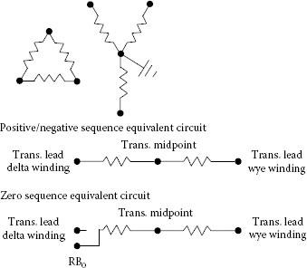
FIGURE 2.18 Transformer equivalent circuit, windings connected delta-wye grounded.
In delta-wye grounded transformers, I0, can flow in each winding, in each phase, but not in the transformer leads connected to the delta winding. 3I0 can flow in the ground circuit connected to the wye-grounded winding.
When transformers are connected delta/wye, wye/wye, or wye/wye-grounded, the equivalent circuit in the zero sequence is an open circuit. The equivalent circuit for a transformer connected delta/wye is shown in Figure 2.19.
Zero sequence impedance of generators, like transformers, depends on the type of winding connection, delta or wye, and if wye, whether the generator is solidly grounded, resistance grounded, reactance grounded, or ungrounded.
Adjacent overhead transmission lines influence the zero sequence impedance of each other. This influence is referred to as mutual impedance.
Figure 2.13 is the negative sequence network with normalized impedances. To calculate a phase to phase fault, the positive and negative sequence networks must be connected as shown in Figure 2.3. This means that one jumper is needed between RB1 and RB2 and a second jumper is needed between the positive sequence fault bus and the corresponding negative sequence fault bus.

FIGURE 2.19 Transformer equivalent circuits, windings connected delta-wye.
2.12 Sample Phase to Ground Fault Calculation: Fault at Bus T2L