
Meltran, Inc.
13.1 Arrester Types and Auxiliary Equipment
13.4 Selection by Energy Rating
Surge arresters are shunt, nonlinear, resistive devices that are installed to limit transient overvoltages, thereby protecting equipment insulation. Sometimes they have been called “lightning arresters,” and this may be due to the fact that many years ago, surge arresters were tailored to protect against the surge front times typical of lightning. They were much less effective against steeper-fronted overvoltages, or against slow-front switching surges. However, the proper term is “surge arresters,” and the modern generation of metal oxide surge arresters is effective against both lightning and switching surges.
The rest of this chapter summarizes metal oxide surge arrester ratings and application principles for system voltage levels above 1 kV. This treatment should suffice for educational purposes. For actual design work, the use of time-domain simulation in an electromagnetic transients program (EMTP) would be highly recommended. The designer should also have access to one of the standard application guides (IEEE C62.22, IEC 60099-5) or the text on insulation coordination by Hileman (1999).
13.1 Arrester Types and Auxiliary Equipment
Nearly 100 years ago, electrode gaps (rod, sphere, or pipe) were used to limit overvoltages on equipment (Sakshaug, 1991). Some of these systems, particularly pipe gaps, may still be in service today. However, the characteristic of gap sparkover voltage vs. surge front time does not match up well with the strength vs. front characteristics of most insulation; that is, it is difficult to coordinate. The next evolutionary step was to add a resistive element in series with the gap, in order to limit the power follow current after an arrester discharge operation. The current limiting would hopefully allow the arrester to clear this power follow current, instead of relying on a nearby breaker or fuse. At the same time, the resistor voltage during a discharge must be low enough that it does not allow an excessive voltage to appear on the protected equipment. These competing requirements led to the use of expensive and complicated nonlinear resistive elements, some involving both solid and liquid materials with high maintenance burdens.
Beginning around 1930, silicon carbide (SiC) was used for the nonlinear resistive elements, leading to much better protective characteristics. Because the SiC would conduct significant current at nominal voltage, it was necessary to provide a sparkover gap that prevents conduction at nominal voltage. After an arrester discharge, these gaps must reseal against the power follow current, otherwise, the arrester would fail thermally. In the mid 1950s, active gaps were developed for SiC arresters. These active gaps contain auxiliary elements that would
1. Preionize the sparkover gap to obtain better surge protective levels
2. Elongate the power follow arc, and move its attachment points, to obtain better interruption performance
SiC arresters were successfully applied on transmission systems up to 345 kV, but some limitations appeared with regard to switching surge protection, energy discharge capability, and pressure relief capability. Having both gaps and SiC blocks, the arrester height increased to the point where it was difficult to vent the pressure buildup during a fault, which limited the arrester’s pressure relief rating. Due to their discharge characteristics vs. frequency or front time, the SiC surge arresters were optimized for lightning. They were less effective for steeper-fronted surges and slow-fronted switching surges.
In the mid 1970s, metal oxide surge arresters were developed into commercial products (Sakshaug et al., 1977). The metal oxide blocks are much more nonlinear than silicon carbide, so that they conduct only a few milliamperes at nominal AC voltage. It eventually became possible to dispense with gaps completely, although earlier designs made some use of gaps (see Figure 13.1). Metal oxide surge arresters have several major advantages over the earlier silicon carbide arresters:
1. Active gaps are not necessary, leading to improved reliability.
2. Metal oxide can discharge much more energy per unit volume than silicon carbide.
3. Metal oxide provides better protection across the range of surge wave fronts than silicon carbide, and in fact, protects effectively against switching surges.
4. The decrease in arrester height, caused by eliminating sparkover gaps, leads to higher pressure relief ratings.
Virtually all new applications will use metal oxide surge arresters. Metal oxide has enabled some new applications, like series capacitor protection and overhead line switching surge control that were not possible with silicon carbide. However, many silicon carbide arresters are still in service. Some investigators have noted high silicon carbide arrester failure rates, due to moisture ingress, after several years of service on medium-voltage distribution systems. This experience does not necessarily apply to surge arresters in substations. If such problems arise, it would make sense to systematically replace silicon carbide arresters on a system. Otherwise, assuming that the original application was proper, the older silicon carbide arresters could remain in service.
Figure 13.1 shows the general use of gaps in surge arresters. The gapped design (Figure 13.1a) applies to silicon carbide, whereas the gapless design (Figure 13.1d) applies to the latest generation of metal oxide. One manufacturer used the shunt gap (Figure 13.1b) in early metal oxide arresters. At steady state, both nonlinear elements would support the nominal voltage, somewhat reducing the current. During a surge discharge, the shunt gap would sparkover to bypass the smaller section of metal oxide, thereby reducing the discharge voltage and providing somewhat better protection. Another manufacturer used the series gap with capacitive grading (Figure 13.1c) in early metal oxide arresters. At steady state, this decreases the voltage on the metal oxide. During a surge discharge, the gap sparks over “immediately” due to the capacitive grading. The latest generations of metal oxide do not need these gaps, although there is some consideration for using gaps to achieve specific goals (e.g., coordinating arresters, withstanding temporary overvoltages).
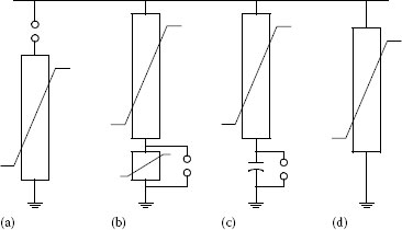
FIGURE 13.1 Use of gaps in metal oxide surge arresters (a) gapped, (b) shunt gap, (c) graded gap, and (d) gapless.
Recently, surge arresters have been applied to transmission lines for lightning protection of the line insulation. Two varieties have been developed, first a nongapped line arrester (NGLA) as in Figure 13.1d, and then an externally gapped line arrester (EGLA) as in Figure 13.1a.
The surge arrester must be installed on something, such as a transformer tank or a pedestal. It must also be connected to the protected system, typically through a wire or lead. Later, it will be shown that these connections have important effects on the overall protection, especially for steep surges. The pedestal and lead, both length and location, must be considered as part of the overall arrester installation.
On distribution systems, a ground lead disconnector is often used with the surge arrester. If the arrester fails and then conducts current on a steady-state basis, the disconnector will detonate and disconnect the base of the arrester from ground. This should happen in approximately 1 s, or faster. The arrester may then remain connected to the system until maintenance personnel have a chance to replace it. No breaker or fuse need operate to isolate the failed arrester; if the arrester is the only thing that failed, no customers need to lose their electric service. Of course, the arrester is not providing any surge protection during this period with its ground lead disconnected. There would be a clear visual indication that the ground lead has been disconnected; it will be “hanging down” below the arrester. Regular visual inspections are necessary to maintain surge protection whenever ground-lead disconnectors are used.
Many surge arresters in substations or industrial facilities have been installed with “surge counters.” These are accessories to be installed in the surge arrester’s ground-lead connection. Two functions may be provided:
1. A steady-state current meter, calibrated in mA. If this current increases over time, it may indicate thermal damage to the surge arrester. However, the presence of harmonics or external leakage currents would complicate the assessment.
2. A counter indicates the number of surge current discharges above a certain threshold, which may depend on frequency or front time. Even if the count is accurate, it does not mean that the discharge voltage reached any particular level during those events.
To use surge counters effectively, it is important to track the readings on a regular basis, beginning at the time of commissioning.
Surge arresters have both a voltage rating and a class, or type. For metal oxide, the important voltage rating is the maximum continuous operating voltage (MCOV), which is the steady-state voltage the arrester could support indefinitely. This rating is most important for metal oxide, because most of these arresters are now gapless and carry a few milliamperes at all times. The MCOV should be at least 1.05 times the system’s nominal line-to-ground voltage. There are some cases like distribution feeders with poor voltage regulation, which might require a higher MCOV. As discussed later, short-term temporary overvoltages (TOV) also play an important role in selecting the arrester rating, but still the basic rating is MCOV.
TABLE 13.1 Schedule of IEC Voltage Rating Steps
Range of Rated Voltage (kV rms) |
Step Size (kV rms) |
3–30 |
1 |
30–54 |
3 |
54–96 |
6 |
96–288 |
12 |
288–396 |
18 |
396–756 |
24 |
Historically, the SiC arresters had a voltage rating that corresponded to the duty cycle test, with no direct link to MCOV. Given that SiC arresters were always gapped, MCOV was not an important concern. In IEEE standards, the old SiC numerical schedule of voltage ratings has been carried over to metal oxide arresters, and the MCOV is usually about 84% of the arrester voltage rating. For example, a typical 108 kV arrester has an MCOV of 84 kV. Only the MCOV number is important.
The IEC standard defines the voltage rating to be the TOV capability at 10 s, and again the MCOV is about 84% of this value. Table 13.1 shows the schedule of IEC voltage rating steps, and in general these line up with the schedule of IEEE voltage ratings. This table could be used to choose the preliminary arrester rating for some application. However, all surge arrester manufacturers now have their catalog information readily available on the web, and it is better to use their actual data.
The IEEE specifies a set of withstand tests for surge arresters, each of them followed by a period of operation at MCOV. These tests are as follows:
1. High current, short duration: Two 4 × 10 μs current surges are discharged through the arrester. The peak current is 65 kA for station, intermediate, and distribution normal-duty arresters. It is 100 kA for distribution heavy-duty and 40 kA for distribution light-duty arresters. This is followed by 30 min at MCOV.
2. Low current, long duration: For station and intermediate arresters, a transmission pi section is discharged 20 times through the arrester. The switching surge voltage ranges from 2.0 to 2.6 pu and the equivalent line length ranges from 160 to 320 km, depending on the arrester class and voltage rating. For distribution arresters, a 2000 ms square wave of current is discharged 20 times, with a peak current of 250 A for heavy-duty and 75 A for normal-duty or light-duty arresters, followed by 30 min at MCOV.
3. Duty cycle test: While energized at the voltage rating, which is higher than MCOV, discharge an 8 × 20 μs lightning impulse 20 times, with peak ranging from 5 to 20 kA, followed by 2 discharges without power frequency voltage, followed by 30 min at MCOV.
4. Pressure relief test: An AC current of 40–80 kA rms (root mean square) is applied for station class, or 16.1 kA for intermediate class, so that the arrester fails. The pressure must vent well enough that any components lie no farther away than the arrester height. Polymer housings tend to have better pressure relief ratings than porcelain housings.
5. Contamination test: Energized for 1 h at MCOV under contaminated conditions, followed by 30 min at MCOV.
6. Temporary overvoltages: Verifies the TOV capability over a range from 0.02 to 1000 s.
7. Switching surge energy: This is an optional supplement to the low-current, long-duration test, which carries an implied energy discharge duty. The manufacturer typically provides a value for energy capability in kJ per kV of MCOV, which is meant to cover multiple discharges within a period of about 1 min.
The test results for TOV and switching surge energy capability are often used in application studies. The manufacturer also conducts tests of the arrester protective characteristics. These are always directly useful in modeling and application studies:
1. 8 × 20 μs discharge voltage: Current surges are applied with peak magnitudes of 1.5, 3, 5, 10, and 20 kA, with the resulting peak discharge voltages tabulated. Due to various frequency-dependent effects, the peak voltage occurs before the peak current. For some ratings, the 15 and 40 kA discharge voltages are also tabulated.
2. Front-of-wave (FOW) protective level: This is the voltage having a 0.5 μs time to crest, for a current surge of 5, 10, 15, or 20 kA depending on the rating. To get this value, it is necessary to apply different front times for the current surge and interpolate or extrapolate the results.
3. Switching surge protective level: The peak arrester voltage for a current surge having 45–60 μs front time and a peak of 500–2000 A depending on the rating.
Many vendors provide more detailed information about protective levels as a function of the surge front time, which is helpful in modeling.
Figure 13.2 shows typical maximum 8 × 20 μs discharge voltage and FOW discharge characteristics for station class metal oxide surge arresters, rated 54 kV and above. There is a manufacturing variation within each product line, and the minimum discharge voltage could be a few percent lower than these values. In most cases, the maximum values would be used for application studies. Figure 13.3 shows a typical maximum switching surge discharge characteristic. All of these are normalized to the published 8 × 20 μs discharge voltage at 10 kA.

FIGURE 13.2 Metal oxide surge arrester lightning discharge characteristics, for voltage ratings from 54 to 360 kV. V10 is the arrester’s 8 × 20 μs discharge voltage at 10 kA.
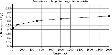
FIGURE 13.3 Metal oxide surge arrester switching discharge characteristic, for voltage ratings from 54 to 360 kV. V10 is the arrester’s 8 × 20 μs discharge voltage at 10 kA.
The IEEE standards define several classes of surge arresters, based on the withstand test levels discussed earlier. In substations and many transmission line applications, the station class arresters are most common. The intermediate class arresters are used for lightning protection of transmission line towers and for some of the smaller substations. The choice of distribution arrester class depends mainly on how severe the local lightning environment is. Although purchased in significant quantities, the surge arresters are typically not a significant cost item in a single substation.
Among the IEEE standards, C62.11 defines the metal oxide arrester tests and ratings, whereas C62.22 provides the application guidance. The older standards for silicon carbide arresters, C62.1 and C62.2, are still available. These apply to the United States, whereas, in most other parts of the world, the International Electrotechnical Committee (IEC) standards are used. These are denoted IEC 60099 parts 1 through 8, except that there is no part 2 and part 7 is a glossary. For gapless metal oxide arresters, part 4 defines the tests and ratings, while part 5 presents the application guidelines. For gapped arresters, including silicon carbide, part 1 applies. The IEEE standards may be found through www.ieee.org, and the IEC standards through www.iec.ch.
Both IEEE and IEC standards define the discharge characteristics in similar ways. The same applies to MCOV and TOV capabilities. In IEC standards, the rated voltage is actually the TOV capability at 10 s and also the duty cycle test voltage. These differences generally will not concern the user. The main difference is that IEC standards classify arresters by nominal discharge current (1.5, 2.5, 5, 10, or 20 kA) and line discharge class (1–5, or none). An IEEE station class arrester is roughly comparable to an IEC 10 kA arrester, whereas the intermediate and distribution class arresters are roughly comparable to IEC 5 kA arresters. At 500 kV and above, the IEEE classifying current is 15 or 20 kA, roughly corresponding to the IEC nominal discharge current of 20 kA used at these voltage levels. The appropriate standard should be consulted for details, but Osterhout (1992) and Hamel and St. Jean (1992) provide overviews of the differences.
Low-voltage surge arrester applications follow a different set of standards and guides, for system voltage levels below 1 kV, which includes secondary services and customer utilization circuits. The applicable IEEE standards are C62.72 and C62.41 for application guidance, plus others in the C62 family for test requirements. The applicable IEC standards for low-voltage power systems are 61643, parts 1 and 12.
As discussed earlier, the first choice of arrester voltage rating is based on MCOV. That would be the lowest and best choice because it minimizes the arrester discharge voltage for any particular surge, thereby maximizing protective margins. However, it may be necessary to increase the arrester voltage rating to withstand either TOV or surge energy content.
The TOVs come from several sources, most commonly
1. During ground faults, voltage on the unfaulted phases will rise above nominal unless the system is solidly grounded. The duration of this overvoltage depends on protective relaying system response, usually less than 1 s, but up to several hours for delta systems or ungrounded systems.
2. When first energizing a long line or cable, the voltage at the open end will rise above nominal due to the Ferranti effect. The duration depends on how long it takes to switch on shunt compensation or to close the other end of the line. A similar effect occurs after load rejection when only one end of the line opens.
3. Harmonics, ferroresonance, and transformer inrush currents can produce dynamic overvoltages that last for several cycles.
Usually the ground fault TOVs are most important, but there are special cases where simulation of other TOVs should be considered. Given the zero sequence and positive sequence impedances at the point of a fault, the per-unit unfaulted phase voltage, often called the earth-fault factor (EFF) may be estimated for a single-line-to-ground fault (IEEE C62.22)

FIGURE 13.4 Temporary overvoltage capability.
(13.1) |
Note that there are two unfaulted phases to evaluate, corresponding to the +j1 and −j1 terms. That voltage should be further increased by a factor of 1.05 to account for above-nominal operating voltage. In most cases, the fault resistance, Rf, should be considered zero as it maximizes EFF. For distribution systems, Rf should be equal to the design level of fault resistance that relaying will detect; this is really a matter of policy. For double-line-to-ground faults, the per-unit voltage on the unfaulted phase would be (IEEE C62.22)
(13.2) |
Again, this voltage should be further increased by a factor of 1.05 to account for above-nominal prefault voltage.
The TOV duties from various sources must be compared to the arrester’s TOV capability, which may be obtained from the manufacturer’s catalog, or taken from Figure 13.4 to use typical data. Some data include TOV capability both with and without earlier surge discharges; the capability with prior discharge, which is always lower, should be used. If the TOV duty exceeds the arrester capability, then a higher voltage rating must be chosen for the arrester, accepting lower protective margins. It is difficult to mitigate TOVs as they typically arise from high-level system design choices.
13.4 Selection by Energy Rating
Surge arresters have a switching surge energy discharge capability higher than implied by the low-current, long-duration discharge test. The vendor may provide this value as kJ per kV of MCOV, or rated voltage with footnotes that specify the number, shape, and interval between surges. For example, if the capability is given as 8 kJ per kV of MCOV for a single discharge, then a 108 kV arrester with an MCOV of 84 kV has a switching surge discharge capability of 672 kJ.
The energy capability may be increased by using two or more columns of metal oxide in parallel. The manufacturer has to match the disks to achieve this and typically two parallel columns provide a bit less than double the energy rating. Note that increasing the arrester voltage rating will not help much, because even though the energy rating increases, the discharge voltage also increases resulting in higher surge energy discharge. Parallel columns will not help with TOV, as TOV is a sustained phenomena supported by the system voltage.
There is some evidence that these energy ratings are actually the point at which failure probability becomes nonzero. Hileman (1999) estimated the probability of failure from several reported tests, assuming a Weibull function to model the failure probability
(13.3) |
where
WR is the energy rating
WC is the calculated energy duty
Under this model, PF reaches 50% only at 2.5 times the energy rating. Note that standards and vendors do not address this point yet, but consideration of the actual failure probability may avoid overdesign for switching surge energy discharge.
A conservative estimate of the switching surge energy discharge, WC, is
(13.4) |
For energy in joules, C is the total capacitance in μF and E is the peak voltage in kV. The peak voltage ranges from 2 to 2.5 pu of the peak line-to-neutral voltage, although it may be higher for cases like capacitor bank restrikes and line reclosing. The total capacitance may come from an overhead line, a cable, or a shunt capacitor bank. Better estimates may be obtained through time-domain simulation.
Lightning surge discharge also poses a significant energy duty on surge arresters. However, the switching surge energy rating does not apply directly and the duty might be better described as a charge duty. In either case, the lightning discharge current may be represented as a decaying exponential with total area equal to the stroke charge. Details of the wave front are unimportant for this evaluation. If one arrester discharges all of the lightning stroke current, a conservative estimate of the energy duty would be
(13.5) |
where
Q is the total stroke charge in coulombs
Ed is the arrester discharge voltage at the peak lightning stroke current
The actual energy discharge is reduced by nonlinear arrester characteristics and by sharing from nearby arresters. Even though nearby arresters will not have matched characteristics, they still share a significant portion of the energy because of inductances between the arresters and also because the characteristics are more linear at lightning discharge current levels than at switching discharge current levels. Time-domain simulation helps to quantify these effects.
Surge arresters are both nonlinear and frequency-dependent devices. The only strictly correct model would be a time-domain simulation at the level of material physics. In most practical cases, one must use a nonlinear resistance with a separate linear circuit to represent frequency-dependent effects. Surge arresters also interact with other equipment that has distributed parameters. Usually the other system nonlinearities are not important, but in special cases some of these effects (e.g., corona) may become significant. In general, arrester application studies need to be done with time-domain simulation in the EMTP or one of its variants like the Alternative Transients Program (ATP).
In the absence of EMTP or ATP, the arrester discharge voltage may be approximated for a given surge current peak and waveshape. First, choose the FOW, 8 × 20 μs, or switching surge characteristic that best matches the waveshape. If the manufacturer’s data are not available, Figures 13.2 and 13.3 may be used with a normalizing value (10 kA discharge) of 2.3 times MCOV. In cases where the discharge current peak is “known,” interpolate with this value to estimate the peak discharge voltage.
More often, though, a voltage surge arrives at the arrester location and the discharge current peak is not known in advance. In the simplest case, the arrester is at the end of a line with known surge impedance, Z, incoming surge magnitude, E, and power frequency offset, Vpf. The arrester current and voltage may then be estimated according to Hileman (1999)
(13.6) |
This approximates the arrester discharge characteristic, Ed, with a straight line having slope RA and intercept E0, as determined by interpolation on either the manufacturer’s data or Figures 13.2 and 13.3. The actual arrester voltage, EA, is the discharge voltage, Ed, plus the power frequency offset voltage, Vpf. To use Equation 13.6, make the first guess at IA and determine the corresponding E0 and RA parameters from the discharge characteristic. Then solve for IA using the first equation; if it falls outside the linear segment used to estimate RA and E0, iterate until convergence on IA. Then Ed and EA may be determined directly. Hileman (1999) presents more detailed estimating methods for other situations, but in those cases it may be easier to use EMTP or ATP.
Figure 13.5 shows three frequency-dependent surge arrester models. The Cigre model (Hileman et al., 1990) works well, but it requires the user to program a time-dependent conductance to simulate the arrester turn-on characteristics. It is not directly applicable to EMTP or ATP. The IEEE model (IEEE PES task force) uses high-frequency and low-frequency discharge characteristics represented by A0 and A1, respectively, with a two-stage RL filter connecting them. At nominal voltage, the arrester current is primarily capacitive, represented by the shunt C component. Both IEEE and Cigre models require iteration of the parameters to represent a particular arrester, before it can be used in application studies. A simplified version of the IEEE model (Magro et al., 2004) has been developed for use “out of the box”; it ignores the capacitive effect.
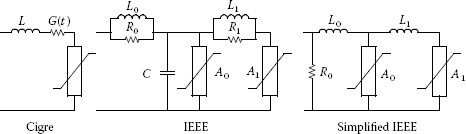
FIGURE 13.5 Frequency-dependent surge arrester models.
In the Cigre model, the turn-on conductance begins at zero and increases with time. A reasonable approximation for distribution arresters is
(13.7) |
where
U10 is the 10 kA discharge voltage in kV
U is the arrester voltage in kV
I is the arrester current in kA
k is a constant ranging between 0.03 and 0.05, depending on the manufacturer
The series inductance, L, is approximately 1 μH per meter of arrester height for outdoor arresters, and one-third of that for gas-insulated substation (GIS) arresters.
The following are starting values for the IEEE model parameters:
(13.8) |
where
d is the arrester height in meters
n is the number of metal oxide columns in parallel
L is in μH
R is in Ω
C is in pF
Parameters for the simplified model are
(13.9) |
The inductance values L0 and L1 are in μH, VFOW is the FOW discharge voltage in kV, V10 is the 8 × 20 μs discharge voltage in kV, and Vn is the arrester voltage rating (not the MCOV), also in kV. R0 is present for numerical stability and may not be required for some time-domain simulators. R0 may also be increased by one or two orders of magnitude for extra high voltage (EHV) levels. Whenever VFOW is not available or when the ratio VFOW/V10 is more than 1.18, the simplified inductance parameters become
(13.10) |
In both IEEE models, A1 closely follows the arrester discharge voltage characteristic for 8 × 20 μs discharge currents. A0 is 20%–30% above A1, such that in parallel and considering the RL filter at high frequency, they approximate the arrester’s FOW protective level (FOWPL). At low frequency, the filter inductances have little impact and A1 dominates the model characteristic.
All of the frequency-dependent models include built-in arrester inductance. The arrester lead and pedestal should also be modeled, along with bus, line, or cable lengths to the nearby protected equipment. The lead and pedestal may be represented either as lumped inductance, approximately 1 μH per meter, or with traveling wave lines having surge impedance of about 300 Ω.
The separation effect may be approximated for an open-end termination, at which traveling wave reflections will cause doubling before the arrester’s limiting effect is seen. The peak voltage at the open end is
(13.11) |
where
Ed is the arrester discharge voltage in kV
S is the surge steepness in kV/μs
τ is the travel time in μs to the open line end
For overhead lines or buswork, τ is approximately the distance in meters, divided by 300. For example, if the arrester discharge voltage is 297 kV, the surge steepness is 1000 kV/μs and the distance to the protected transformer is 10 m, then the peak transformer voltage, ET, is approximately 364 kV. That is an increase of 22% from 297 kV, illustrating the importance of minimizing lead lengths. Note that this estimate ignores the effect of transformer capacitance and power frequency offset, both of which would further increase ET.
In many cases, the ground resistance does not have to be included. The main exceptions occur when arresters are applied outside of the substation, such as riser poles, distribution transformers, and transmission line towers. In the riser pole application, a ground connection affects the differential-mode surge entering the cable. On distribution lines, the multigrounded neutral conductor allows current to circulate back through nearby arresters. The same thing happens with transmission line arresters installed with overhead shield wires. In all these cases, the ground resistances should be modeled, along with any conductors that are grounded periodically.
If it is necessary to model an older SiC arrester, the 8 × 20 μs discharge characteristic is represented very well by a single exponential power law
(13.12) |
This must be connected in series with a gap, having a sparkover voltage ranging anywhere from 5% to 20% higher than V10. The exponential power, α, ranges from two to six, with higher values being more typical for SiC surge arresters. If the actual data are no longer available, it may be assumed that the 10 kA discharge voltage is approximately equal to the 10 kA, 8 × 20 μs discharge voltage of a metal oxide arrester having the same voltage rating (Sakshaug, 1991). On that assumption, the value of k becomes, for units of kA and kV,
(13.13) |
Typical SiC data may also be found in Greenwood (1991). Both the FOW and switching surge protective levels for SiC arresters would be significantly higher than for metal oxide arresters of the same voltage rating, even when the V10 values are approximately equal. Conversely, the α parameter in metal oxide varies with current, so that a single exponential does not provide a good model. Piecewise exponential segments are often used for metal oxide surge arrester models in EMTP and ATP.
Perhaps the most important surge arrester application is to protect the equipment in a substation. After selecting the lowest possible arrester voltage rating, one typically applies an arrester as close as possible to each transformer terminal. Then given the transformer BIL, a protective margin is calculated using the 8 × 20 μs discharge voltage at the “coordination current,” which is typically 10 kA:
(13.14) |
where
Mpct is the protective margin, in percent
BIL is the transformer basic insulation level, in kV
V10 is the arrester’s 10 kA discharge voltage, in kV
The margin could also be calculated at a different coordination current, such as 5 or 20 kA, in which case V5 or V20 would be used instead of V10. One could also calculate a chopped wave protective margin, using the chopped wave insulation level and FOWPL in place of BIL and V10. Finally, one could calculate a margin for switching surges using the BSL and the arrester’s switching surge protective level. In all cases the principle applied is the same and 10%–20% should be considered the minimum acceptable margin. These margins are usually easy to obtain. For example, on a 138 kV system, the transformer BIL is at least 450 kV. If the system is effectively grounded, a 108 kV arrester might be used with a 10 kA discharge voltage of 263 kV, providing a margin of 71%. Using a 120 kV arrester with 297 kV discharge voltage, the margin is still 52%.
As discussed in Chapter 14, many uncertainties and deviations complicate the use of margins. After a long time in service, the insulation strength may not really be at the original BIL and BSL levels. The actual surges also differ from laboratory test waves, so that the BIL and BSL do not describe the insulation strength perfectly. Furthermore, several important electrical circuit phenomena are not considered in the simple use of margins and Figure 13.6 illustrates some of them.
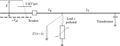
FIGURE 13.6 Station protection by surge arresters.
The surge arrester’s lead and pedestal connections should be added to the basic arrester model, either as lumped inductances or as very short distributed-parameter lines. As a result, the voltage to ground at the point of arrester connection will be somewhat higher than the pure arrester discharge voltage. The distances to protected equipment, LB and LT in Figure 13.6, should also be represented with distributed-parameter lines. The arrester itself should be represented with a frequency-dependent model, as discussed earlier. At these high frequencies, the transformer should be represented as a capacitance ranging from 1 to 10 nF, with some sensitivity analysis of this parameter. The incoming surge itself is primarily described with a steepness, S, ranging from 1000 to 2000 kV/μs, depending on the transmission line characteristics, lightning environment, and design level of mean time between failures. The surge magnitude, E, is typically based on some percentage of the line insulation critical flashover (CFO) voltage. It arrives on top of an opposite-polarity power frequency offset, so the arriving surge voltage to ground is actually E – Vpf. All of these factors tend to increase the peak voltage appearing at the transformer, which decreases the protective margin. Note: when using EMTP, the margin is calculated from the simulated peak voltage at the transformer, instead of V10.
If two or more lines enter the station, which is typically the case, the additional lines tend to increase protective margins. As an approximation, these lines may be represented with the line surge impedances to ground, connected in parallel at the point of arrester connection. This is shown in Figure 13.6, where n is the total number of lines entering the station. A better representation would be to represent the bus sections with distributed-parameter lines, and connect the line entrances at points where they actually enter the station.
A further refinement is to represent the surge with a Thevenin equivalent. The simplest such equivalent is a surge voltage of 2E on top of a DC voltage equal to −Vpf, both behind a lumped resistance equal to the line surge impedance, Z. The next refinement would be to represent the line with distributed parameters back to the stroke point, with a tower footing resistance value in place of Z. Even with these refinements, a single-phase model is adequate for the simulation.
Sometimes, the switching surge energy discharge duty on a station arrester will exceed its rating. Typically this happens when large shunt capacitor banks, or long cables, are nearby. The arrester can be ordered with parallel columns, which are matched at the time of manufacturing to achieve effective sharing of the energy duty. If not matched, a small difference in the discharge characteristic could result in one column discharging virtually all of the energy. This would happen even with typical small manufacturing variations of 3% or less.
Once the model in Figure 13.6 has been set up, the arrester rating and location will be finalized to adequately protect each transformer. Protective margins for other equipment will also be available, such as the circuit breaker in Figure 13.6. For many stations, arresters at the transformer terminals will adequately protect all equipment in the station. If not, arresters can be added to protect equipment that is far away from the transformers. This process applies to each nominal voltage level in the substation.
As a further constraint, the arresters on two different voltage levels should be coordinated so that the high-side arrester always operates first for a surge impinging on the high side of the transformer. If the low-side arresters operate first, they might discharge all of the energy in the high-side surge, leading to possible failure. This coordination is achieved by ensuring 4% margin between the transformer turns ratio and the ratio of arrester protective levels. For example, a 345/138 transformer has a turns ratio of 2.5. The switching surge discharge voltage of the high-side arrester should be no more than 2.5/1.04, or 2.4 times the switching surge discharge voltage of the low-side arrester.

FIGURE 13.7 Transmission line protection by surge arresters.
Figure 13.7 shows how surge arresters may be used to protect overhead transmission lines. Arresters on the line side of a circuit breaker, shown to the left in Figure 13.7, can protect the breaker from lightning surges traveling in from the line, while the breaker is open. If the breaker is open for maintenance, a disconnect switch would be opened to isolate it from the line. The need for protection would arise when the breaker opens to clear a lightning-induced fault during a storm, and then a subsequent lightning stroke to the line causes another surge while the breaker is still open. As this condition occurs rarely, some utilities may not use arresters to provide this protection.
On long EHV transmission lines, surge arresters may be applied at each end to mitigate switching surges during line energization and reclosing. A statistical switching study using either EMTP or a transient network analyzer (TNA) is required for this application. The overvoltages will be higher at intermediate points along the line, due to separation effects. The study results should include a profile of probabilistic switching overvoltage parameters vs. line length, to be used with a probabilistic evaluation of the switching surge flashover rate. Commonly used alternatives to these line-end arresters include preinsertion resistors in the circuit breakers or controlled-closing circuit breakers. While often more expensive and more complicated, these alternatives typically produce a flatter overvoltage profile along the line length.
Some EHV transmission lines use series capacitors to reduce their electrical length, and during faults on the line, very high voltages would result on the capacitors. Metal oxide surge arresters typically protect these capacitor banks, as shown in Figure 13.7. The energy dissipation requirements are severe and the manufacturer takes extra care to ensure that the parallel metal oxide columns are matched so that each column shares the energy and current duty. The blocks may also be larger than in typical station-class surge arresters. Although the transient phenomena is at power frequency and subsynchronous frequencies, these energy calculations are normally done using EMTP.
Recently, arresters have been applied to transmission line towers to provide lightning protection of the line insulation. These may be used in place of, or in addition to, overhead shield wires. Some manufacturers have special-purpose line arresters, which are comparable to intermediate or distribution heavy-duty class. Arresters may be used in addition to a shield wire in areas where low footing resistance is difficult to achieve or in high-exposure areas like river crossings. In that case, the arrester energy duty is lessened because the shield wire and footing discharge most of the lightning stroke current. Without a shield wire, the energy duties will increase but are still mitigated by sharing from the arresters on nearby towers.
Arresters on transmission towers can have high protective levels, well above the anticipated switching surge and TOV levels, but still low enough to protect the line insulation during lightning stroke discharges. As a result, these line arresters have a smaller block diameter and lower energy discharge capability than station class arresters. The protective level of an EGLA is approximately equal to the gap sparkover voltage, or the 1 kA discharge voltage of the metal oxide. However, success or failure of this application depends more on the ability to withstand vibration and other mechanical stresses, rather than electrical performance.

FIGURE 13.8 Distribution transformer protection by surge arresters.
Surge arresters protect virtually all distribution transformers connected to overhead lines, as illustrated in Figure 13.8. It is essential to keep the lead length short. The historical rules of thumb like “2 kV per foot” are grossly understated, because they were based on laboratory test waveshapes that do not represent natural lightning surges. If the arrester is installed between a small fuse and the transformer, then the arrester discharge current must also flow through the fuse, which may cause the fuse to melt unnecessarily. If this becomes a problem, larger fuses or completely self-protected transformers (CSPs), which have internal fuses, could help mitigate it.
Because the arrester is connected between the transformer tank and terminal, pole ground resistance and pole download inductance do not have a direct impact on the transformer’s protective margin. However, if the pole ground resistance is too high with respect to the house or customer ground resistance, higher surge currents will circulate in the secondary service drop and the customer load equipment. This may lead to failures due to surges in the transformer secondary, or damage to customer equipment, even when the transformer primary enjoys a comfortable protective margin. It has been suggested that transformers with interlaced secondary windings are less susceptible to these failures. In any case, the secondary surges should be limited by using triplex service drops rather than open-wire drops, and also by keeping the utility pole ground resistance to a reasonably low value.
Given the dispersed installation of transformers on a distribution feeder, surge arresters will be installed at relatively close spacings on the distribution line. Typical average spacings might be from two to four poles in built-up areas, although not necessarily on all phases. These arresters may be used to provide some protection from lightning flashovers of the line insulation. Because of the low insulation levels, typically 100–300 kV CFO, this protection will generally be more effective for induced voltages from nearby lightning strokes, which do not actually hit the line. For direct strokes to the line, energy duty on the arresters may be too high, although there is little field experience to indicate that arresters are failing at high rates due to lightning. If the arresters are not placed at every pole and on every phase, separation effects will be more significant than in a typical substation. Some trials have been done with arresters on just the topmost phase, reasoning that the arrester will convert that phase conductor into a shield wire during a lightning discharge. However, the topmost phase is typically not high enough to serve as an effective shield wire for the two outside phase conductors. Many distribution engineers feel that a direct stroke to the line will result in either a line insulation flashover, or less often, an arrester failure.
Figure 13.9 shows the application of surge arresters at the riser pole, where an underground cable segment connects to an overhead primary distribution feeder. The riser pole arrester limits a surge entering the cable, but surge doubling may occur at the cable end and tap points. If the lightning surge is “bipolar,” the surge may even quadruple at the open cable ends (Barker, 1990). If the nominal voltage and cable lengths are low enough and setting aside the small risk of voltage quadrupling, the riser pole arrester may be sufficient. For longer cables, it may be necessary to add arresters at some of the open cable ends or tap points. Before taking that step, the effect of “scout arresters,” shown at either end of the overhead feeder section in Figure 13.9, should be included in the study. These arresters will mitigate most surges arriving at the riser pole.

FIGURE 13.9 Riser pole and scout arresters on a distribution system.
Barker, P.P., Voltage quadrupling on a UD cable, IEEE Trans. Power Delivery, 5(1), 498–501, January 1990.
Greenwood, A.N., Electrical Transients in Power Systems, chap. 16, Protection of systems and equipment against transient overvoltages. 2nd edn., John Wiley & Sons, New York, 1991, pp. 533–534.
Hamel, A. and St. Jean, G., Comparison of ANSI, IEC, and CSA standards’ durability requirements on station-type metal oxide surge arresters for EHV power systems, IEEE Trans. Power Delivery, 7(3), 1283–1298, July 1992.
Hileman, A.R., Insulation Coordination for Power Systems, Marcel Dekker, Inc., New York, 1999, pp. 497–675.
Hileman, A.R., Roguin, J., and Weck, K.H., Metal oxide surge arresters in AC systems—Part v: Protection performance of metal oxide surge arresters, Electra, 133, 133–144, December 1990.
IEC Standard 60099-1, Edition 3.1, Surge Arresters—Part 1: Nonlinear Resistor Type Gapped Surge Arresters for A.C. Systems, International Electrotechnical Commission, December 1999.
IEC Standard 60099-3, Edition 1.0, Surge Arresters—Part 3: Artificial Pollution Testing of Surge Arresters, International Electrotechnical Commission, September 1990.
IEC Standard 60099-4, Edition 2.2, Surge Arresters—Part 4: Metal Oxide Surge Arresters without Gaps for AC Systems, International Electrotechnical Commission, May 2009.
IEC Standard 60099-5, Edition 1.1, Surge Arresters—Part 5: Selection and Application Recommendations, International Electrotechnical Commission, March 2000.
IEC Standard 60099-6, Edition 1.0, Surge Arresters—Part 6: Surge Arresters Containing Both Series and Parallel Gapped Structures—Rated 52 kV and Less, International Electrotechnical Commission, August 2002.
IEC Standard 60099-7, Edition 1.0, Surge Arresters—Part 7: Glossary of Terms and Definitions, International Electrotechnical Commission, April 2004.
IEC Standard 60099-8, Edition 1.0, Surge Arresters—Part 8: Metal-Oxide Surge Arresters with External Series Gap (EGLA) for Overhead Transmission and Distribution Lines of A.C. Systems above 1 kV, International Electrotechnical Commission, January 2011.
IEC Standard 61643-1, Edition 2.0, Low-Voltage Surge Protective Devices—Part 1: Surge Protective Devices Connected to Low-Voltage Power Distribution Systems—Requirements and Tests, International Electrotechnical Commission, May 2003.
IEC Standard 61643-12, Edition 2.0, Low-Voltage Surge Protective Devices—Part 12: Surge Protective Devices Connected to Low-Voltage Power Distribution Systems—Selection and Application Principles, International Electrotechnical Commission, November 2008.
IEEE PES Task Force on Data for Modeling System Transients, Parameter determination for modeling system transients—Part v: Surge arresters, IEEE Trans. Power Delivery, 20(3), 2073–2078, July 2005.
IEEE Std. C62.11-2005, IEEE Standard for Metal-Oxide Surge Arresters for AC Power Circuits (>1 kV), Institute of Electrical and Electronic Engineers, March 2006.
IEEE Std. C62.11a-2008, IEEE Standard for Metal-Oxide Surge Arresters for AC Power Circuits (>1 kV) Amendment 1: Short-Circuit Tests for Station Intermediate and Distribution Arresters, Institute of Electrical and Electronic Engineers, July 2008.
IEEE Std. C62.22-2009, IEEE Guide for the Application of Metal-Oxide Surge Arresters for Alternating-Current Systems, Institute of Electrical and Electronic Engineers, July 2009.
IEEE Std. C62.41.1-2002, IEEE Guide on the Surge Environment in Low-Voltage (1000 V and Less) AC Power Circuits, Institute of Electrical and Electronic Engineers, November 2002.
IEEE Std. C62.41.2-2002, IEEE Recommended Practice on Characterization of Surges in Low-Voltage (1000 V and Less) AC Power Circuits, Institute of Electrical and Electronic Engineers, November 2002.
IEEE Std. C62.72-2007, IEEE Guide for the Application of Surge-Protective Devices for Low-Voltage (1000 V or Less) AC Power Circuits, Institute of Electrical and Electronic Engineers, August 2007.
IEEE Std. C62.1-1989, IEEE Standard for Gapped Silicon Carbide Surge Arresters for AC Power Circuits, Institute of Electrical and Electronic Engineers, April 1990.
IEEE Std. C62.2-1987, IEEE Guide for the Application of Gapped Silicon-Carbide Surge Arresters for Alternating-Current Systems, Institute of Electrical and Electronic Engineers, April 1989.
Magro, M.C., Giannettoni, M., and Pinceti, P., Validation of ZnO surge arrester model for overvoltage studies, IEEE Trans. Power Delivery, 19(4), 1692–1695, October 2004.
Osterhout, J.C., Comparison of IEC and U.S. standards for metal oxide surge arresters, IEEE Trans. Power Delivery, 7(4), 2002–2011, October 1992.
Sakshaug, E.C., A brief history of AC surge arresters, IEEE Power Eng. Rev., 40, 11–13, August 1991.
Sakshaug, E.C., Kresge, J.S., and Miske, S.A., A new concept in arrester design, IEEE Trans. Power Appar. Syst., 96(2), 647–656, March/April 1977.