Software is complex, one of the most complex endeavors humankind has ever undertaken. When you first read the requirements document for a large-scale programming project, you may feel overwhelmed. That’s expected; the task is overwhelming! For this reason, large-scale programming projects typically begin with analysis.
The analysis phase of a project consists of the time spent exploring the problem domain in order to understand the problem completely, clarify the requirements, and resolve any ambiguities between the client’s and developer’s domains. Without fully understanding the problem, you, as the architect or developer, have absolutely no chance of developing a maintainable design. For the case study chosen for this book, however, the domain should be familiar (if not, you may wish to pause here and partake in an analysis exercise). Therefore, we skip a formal, separate analysis phase. That said, aspects of analysis can never be skipped entirely, and we will explore several analysis techniques during the construction of our design. This intentional coupling of analysis and design emphasizes the interplay between these two activities to demonstrate that even for the simplest of problem domains, producing a good design requires some formal techniques for analyzing the problem.
One of the most important techniques we have as software designers for addressing inherent problem complexity is hierarchical decomposition. Most people tend to decompose a problem in one of two ways: top-down or bottom-up. A top-down approach starts by looking at the whole picture and subsequently subdividing the problem until reaching the bottom-most level. In software design, the absolute bottom-most level would be individual function implementations. However, a top-down design might stop short of implementation and conclude by designing objects and their public interfaces. A bottom-up approach would start at the individual function or object level and combine components repeatedly until eventually encompassing the entire design.
For our case study, both top-down and bottom-up approaches will be used at various stages of the design. I find it practical to begin decomposition in a top-down fashion until bulk modules and their interfaces are defined and then actually design these modules from the bottom-up. Before tackling the decomposition of our calculator, let’s first begin by examining the elements of a good decomposition.
2.1 The Elements of a Good Decomposition
What makes a decomposition good? Obviously, we could just randomly split functionality into different modules and group completely unconnected components. Using the calculator as an example, we could place arithmetic operators and the GUI in one module while placing trigonometric functions with the stack and error handling in another module. This is a decomposition, just not a very useful one.
In general, a good design will display attributes of modularity, encapsulation, cohesion, and low coupling. Many developers will have already seen many of the principles of a good decomposition in the context of object-oriented design. After all, breaking code into objects is, itself, a decomposition process. Let’s first examine these principles in an abstract context. Subsequently, we’ll ground the discussion by applying these principles to pdCalc.
Modularity, or breaking components into independently interacting parts (modules), is important for several reasons. First, it immediately allows one to partition a large, complex problem into multiple, smaller, more tractable components. While trying to implement code for the entire calculator at once would be difficult, implementing an independently functioning stack is quite reasonable. Second, once components are split into distinct modules, tests can be defined that validate individual modules instead of requiring the entire program to be completed before integration testing commences. Third, for large projects, if modules with clear boundaries and interfaces are defined, the development effort can be divided between multiple programmers (or teams of programmers) preventing them from constantly interfering with one another’s progress by needing to modify the same source files.
The remaining principles of good design, encapsulation, cohesion, and low coupling all describe characteristics that modules should possess. Basically, they prevent spaghetti code. Encapsulation, or information hiding, refers to the idea that once a module is defined, its internal implementation (data structures and algorithms) remains hidden from other modules. Correspondingly, a module should not make use of the private implementation of any other module. That is not to say that modules should not interact with one another. Rather, encapsulation insists that modules interact with one another only through clearly defined and, preferably, limited interfaces. This distinct separation ensures that internal module implementation can be independently modified without concern for breaking external, dependent code, provided the interfaces remain fixed and the contracts guaranteed by the interfaces are met.
Cohesion refers to the idea that the code inside a module should be self-consistent or, as the name implies, cohesive. That is, all of the code within a module should logically fit together. Returning to our example of a poor calculator design, a module mixing arithmetic code with user interface code would lack cohesion. No logical ties bind the two concepts together (other than that they are both components of a calculator). While a small code, like our calculator, would not be completely impenetrable if it lacked cohesion, in general, a large, noncohesive code base is very difficult to understand, maintain, and extend.
Poor cohesion can manifest in one of two ways: either code that should not be together is crammed together or code that should be together is split apart. In the first instance, code functionality is almost impossible to decompose into mentally manageable abstractions because no clear boundaries exist between logical subcomponents. In the latter situation, reading or debugging unfamiliar code (especially for the first time) can be very frustrating because a typical execution path through the code jumps from file to file in a seemingly random fashion. Either manifestation is counterproductive, and we thus prefer cohesive code.
Finally, we examine coupling. Coupling represents the interconnectedness of components, be it functional coupling or data coupling. Functional coupling occurs when the logical flow of one module requires calling another module to complete its action. Conversely, data coupling is when data is shared between individual modules either via direct sharing (e.g., one or more modules point to some set of shared data) or via passing of data (e.g., one module returning a pointer to an internal data structure to another module). To argue for zero coupling is clearly absurd because this state would imply that no module could communicate in any way with any other module. However, in good design, we do strive for low coupling. How low should low be? The glib answer is as low as possible while still maintaining the ability to function as necessary. The reality is that minimizing coupling without detrimentally complicating code is a skill acquired with experience. As with encapsulation, low coupling is enabled by ensuring that modules communicate with one another only through cleanly defined, limited interfaces. Code that is highly coupled is difficult to maintain because small changes in one module’s design may lead to many unforeseen, cascading changes through seemingly unrelated modules. Note that whereas encapsulation protects module A from internal implementation changes to module B, low coupling protects module A from changes to the interface of module B.
2.2 Selecting an Architecture
Although it is now tempting to follow our preceding guidelines and simply start decomposing our calculator into what seem like sensible constituent components, it’s best to first see if someone else has already solved our problem. Because similar problems tend to arise frequently in programming, software architects have created a catalog of templates for solving these problems; these archetypes are called patterns. Patterns typically come in multiple varieties. Two categories of patterns that will be examined in this book are design patterns [11] and architectural patterns.
Design patterns are conceptual templates used to solve similar problems that arise during software design; they are typically applied to local decisions. We will encounter design patterns repeatedly throughout this book during the detailed design of our calculator. Our first top level of decomposition, however, requires a pattern of global scope that will define the overarching design strategy, or software architecture. Such patterns are naturally referred to as architectural patterns.
Architectural patterns are conceptually similar to design patterns; the two differ primarily in their domains of applicability. Whereas design patterns are typically applied to particular classes or sets of related classes, architectural patterns typically outline the design for an entire software system. Note that I refer to a software system rather than a program because architectural patterns can extend beyond simple program boundaries to include interfaces to hardware, networking, security, databases, the coupling of multiple independent programs, etc. Complex architectural patterns for entire systems are prevalent in modern, cloud-deployed solutions.
Two architectural patterns of particular interest for our case study are the multitiered architecture and the model-view-controller (MVC) architecture. We’ll examine each of these two patterns in the abstract before applying them to pdCalc. The successful application of an architectural pattern to our case study will represent the first level of decomposition for the calculator.
2.2.1 Multitiered Architecture
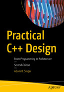
A multitiered architecture with arrows indicating communication
The most common form of the multitiered architecture is the three-tiered architecture. The first tier is the presentation layer, which consists of all of the user interface code. The second tier is the logic layer, which captures the so-called business logic of the application. The third tier is the data layer, which, as the name implies, encapsulates the data for the system. Very often, the three-tiered architecture is applied as a simplistic enterprise-level platform, where each tier could represent not only a different local process but also possibly a different process operating on a different machine. In such a system, the presentation layer would be the client interface, whether it be a traditional desktop application or a browser-based interface. The logic layer of the program could run on either the client or server side of the application or, possibly, on both. Finally, the data layer would be represented by a database that could be running locally or remotely. However, as we shall see with pdCalc, the three-tiered architecture can also be applied to a single desktop application.
Let’s examine how the three-tiered architecture obeys our general decomposition principles. First and foremost, at the highest level of decomposition, the architecture is modular. At least three modules, one for each tier, exist. However, the three-tiered architecture does not preclude multiple modules from existing at each tier. If the system were large enough, each of the primary modules would warrant subdivision. Second, this architecture encourages encapsulation, at least between tiers. While one could foolishly design a three-tiered architecture where adjacent tiers accessed private methods of neighboring tiers, such a design would be counterintuitive and very brittle. That said, in applications where the tiers coexist in the same process space, it is very easy to intertwine the layers, and care must be taken to ensure this situation does not arise. This separation is achieved by clearly delineating each layer via definitive interfaces. Third, the three-tiered architecture is cohesive. Each tier of the architecture has a distinct task, which is not commingled with the tasks of the other tiers. Finally, the three-tiered architecture truly shines as an example of limited coupling. By separating each of the tiers via clearly defined interfaces, each tier can change independently of the others. This feature is particularly important for applications that must execute on multiple platforms (only the presentation layer changes platform to platform) or applications that undergo unforeseen replacement of a given tier during their lifetimes (e.g., the database must be changed due to a scalability problem).
2.2.2 Model-View-Controller (MVC) Architecture
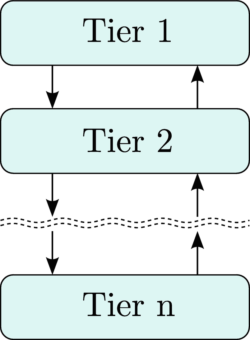
In the model-view-controller (MVC) architecture , components are decomposed into three distinct elements aptly named the model, the view, and the controller. The model abstracts the domain data, the view abstracts the user interface, and the controller manages the interaction between the model and the view. Often, the MVC pattern is applied locally to individual GUI widgets at the framework level where the design goal is to separate the data from the user interface in situations where multiple distinct views may be associated with the same data. For example, consider a scheduling application with the requirement that the application must be able to store dates and times for appointments, but the user may view these appointments in a calendar that can be viewed by day, week, or month. Applying MVC, the appointment data would be abstracted by a model module (likely, a class in an object-oriented framework), and each calendar style would be abstracted by a distinct view (likely, three separate classes). A controller would be introduced to handle user events generated by the views and to manipulate the data in the model.
An MVC architecture with arrows indicating communication. Solid lines indicate direct communication. Dashed lines indicate indirect communication (e.g., via eventing) [38]
As we did with the three-tiered architecture, let’s now examine how MVC obeys our general decomposition principles. First, an MVC architecture will usually be broken into at least three modules: model, view, and controller. However, as with the three-tiered architecture, a larger system will admit more modules because each of the model, view, and controller will require subdivision. Second, this architecture also encourages encapsulation. The model, view, and controller should only interact with one another through clearly defined interfaces, where events and event handling are defined as part of an interface. Third, the MVC architecture is cohesive. Each component has a distinct, well-defined task. Finally, we ask if the MVC architecture is loosely coupled. By inspection, this architectural pattern is more tightly coupled than the three-tiered architecture because the presentation layer and the data layer are permitted to have direct dependencies. In practice, these dependencies are often limited either through loosely coupled event handling or via polymorphism with abstract base classes. Typically, however, this added coupling does usually relegate the MVC pattern to applications in one memory space. This limitation directly contrasts with the flexibility of the three-tiered architecture, which may span applications over multiple memory spaces.
2.2.3 Architectural Patterns Applied to the Calculator
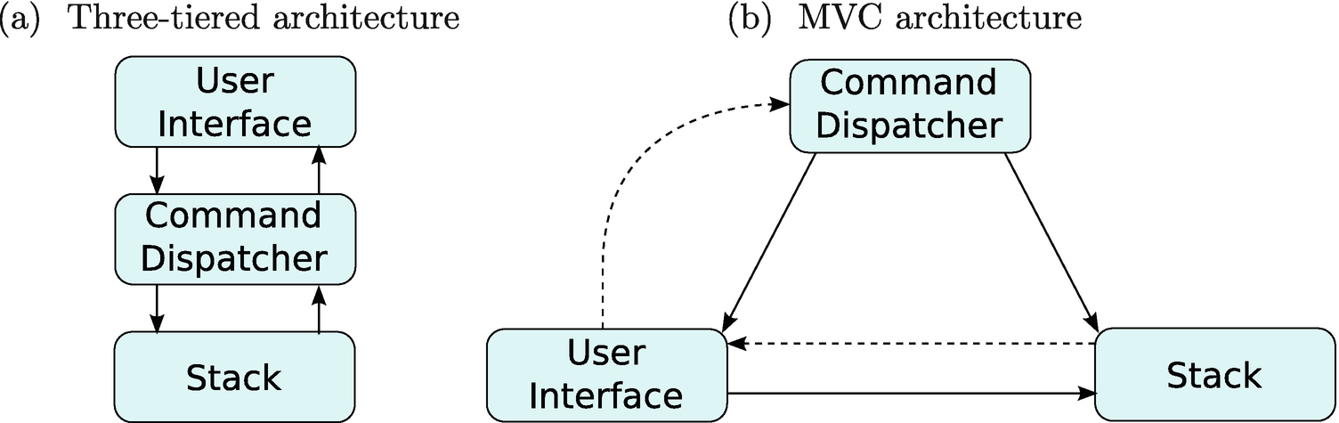
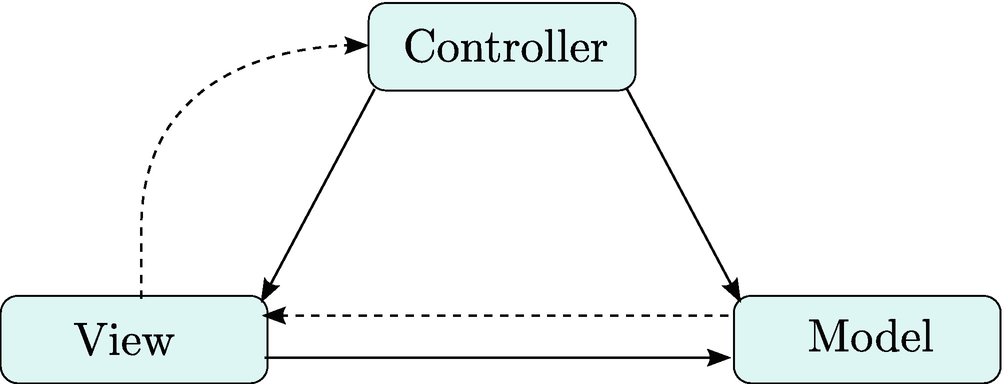
Calculator architecture options
2.2.4 Choosing the Calculator’s Architecture
From Figure 2-3, one quickly identifies that the two architectures partition the calculator into identical modules. In fact, at the architectural level, these two competing architectures differ only in their coupling. Therefore, in selecting between these two architectures, we only need to consider the design trade-offs between their two communication patterns.
Obviously, the main difference between the three-tiered architecture and the MVC architecture is the communication pattern between the user interface (UI) and the stack. In the three-tiered architecture, the UI and stack are only allowed to communicate indirectly through the command dispatcher. The biggest benefit of this separation is a decrease in coupling in the system. The UI and the stack need to know nothing about the interface of the other. The disadvantage, of course, is that if the program requires significant direct UI and stack communication, the command dispatcher will be required to broker this communication, which decreases the cohesion of the command dispatcher module. The MVC architecture has the exact opposite trade-off. That is, at the expense of additional coupling, the UI can directly exchange messages with the stack, avoiding the awkwardness of the command dispatcher performing added functionality unrelated to its primary purpose. Therefore, the architecture decision reduces to examining whether or not the UI frequently needs a direct connection to the stack.
In an RPN calculator, the stack acts as the repository for both the input and output for the program. Frequently, the user will wish to see both the input and output exactly as it appears on the stack. This situation favors the MVC architecture with its direct interaction between the view and the data. That is, the calculator’s view does not require the command dispatcher to translate the communication between the data and the user because no transformation of the data is required. Therefore, I selected the model-view-controller as the architecture for pdCalc. The advantages of the MVC architecture over the three-tiered architecture are, admittedly, small for our case study. Had I instead chosen to use the three-tiered architecture, pdCalc still would have had a perfectly valid design.
2.3 Interfaces
Although it might be tempting to declare our first level of decomposition complete with the selection of the MVC architecture, we cannot yet declare victory. While we have defined our three highest-level modules, we must also define their public interfaces. However, without utilizing some formal method for capturing all the data flows in our problem, we are very likely to miss key necessary elements of our interface. We therefore turn to an object-oriented analysis technique, the use case.
A use case is an analysis technique that generates a description of a specific action a user has with a system. Essentially, a use case defines a workflow. Importantly, a use case does not specify an implementation. The customer should be consulted during use case generation, particularly in instances where a use case uncovers an ambiguity in the requirements. Details concerning use cases and use case diagrams can be found in Booch et al. [9].
For the purpose of designing interfaces for pdCalc’s high-level modules, we will first define the use cases for an end user interacting with the calculator. Each use case should define a single workflow, and we should provide enough use cases to satisfy all of the technical requirements for the calculator. These use cases can then be studied to discover the minimal interactions required between the modules. These communication patterns will define the modules’ public interfaces. An added benefit of this use case analysis is that if our existing modules are insufficient to implement all of the workflows, we will have uncovered the need for additional modules in our top-level design.
2.3.1 Calculator Use Cases
Let’s create the use cases for our requirements. For consistency, use cases are created in the order in which they appear in the requirements.
Use Case: User enters a floating-point number onto the stack
Scenario: The user enters a floating-point number onto the stack. After entry, the user can see the number on the stack.
Exception: The user enters an invalid floating-point number. An error condition is displayed.
Use Case: User undoes last operation
Scenario: The user enters the command to undo the last operation. The system undoes the last operation and displays the previous stack.
Exception: There is no command to undo. An error condition is displayed.
Use Case: User redoes last operation
Scenario: The user enters the command to redo the last operation. The system redoes the last operation and displays the new stack.
Exception: There is no command to redo. An error condition is displayed.
Use Case: User swaps top stack elements
Scenario: The user enters the command to swap the top two elements on the stack. The system swaps the top two elements on the stack and displays the new stack.
Exception: The stack does not have at least two numbers. An error condition is displayed.
Use Case: User drops the top stack element
Scenario: The user enters the command to drop the top element from the stack. The system drops the top element from the stack and displays the new stack.
Exception: The stack is empty. An error condition is displayed.
Use Case: User clears the stack
Scenario: The user enters the command to clear the stack. The system clears the stack and displays the empty stack.
Exception: None. Let clear succeed even for an empty stack (by doing nothing).
Use Case: User duplicates the top stack element
Scenario: The user enters the command to duplicate the top element on the stack. The system duplicates the top element on the stack and displays the new stack.
Exception: The stack is empty. An error condition is displayed.
Use Case: User negates the top stack element
Scenario: The user enters the command to negate the top element on the stack. The system negates the top element on the stack and displays the new stack.
Exception: The stack is empty. An error condition is displayed.
Use Case: User performs an arithmetic operation
Scenario: The user enters the command to add, subtract, multiply, or divide. The system performs the operation and displays the new stack.
Exception: The stack size is insufficient to support the operation. An error condition is displayed.
Exception: Division by zero is detected. An error condition is displayed.
Use Case: User performs a trigonometric operation
Scenario: The user enters the command for sin, cos, tan, arcsin, arccos, or arctan. The system performs the operation and displays the new stack.
Exception: The stack size is insufficient to support the operation. An error condition is displayed.
Exception: The input for the operation is invalid (e.g., arcsin(−50) would produce an imaginary result). An error condition is displayed.
Use Case: User performs y x
Scenario: The user enters the command for yx . The system performs the operation and displays the new stack.
Exception: The stack size is insufficient to support the operation. An error condition is displayed.
Exception: The input for the operation is invalid (e.g., −10.5 would produce an imaginary result). An error condition is displayed.
Use Case: User performs ![$$ sqrt[oldsymbol{x}]{oldsymbol{y}} $$](https://imgdetail.ebookreading.net/2023/10/9781484274071/9781484274071__9781484274071__files__images__454125_2_En_2_Chapter__454125_2_En_2_Chapter_TeX_IEq1.png)
Scenario: The user enters the command for
![$$ sqrt[x]{y} $$](https://imgdetail.ebookreading.net/2023/10/9781484274071/9781484274071__9781484274071__files__images__454125_2_En_2_Chapter__454125_2_En_2_Chapter_TeX_IEq2.png) . The system performs the operation and displays the new stack.
. The system performs the operation and displays the new stack.Exception: The stack size is insufficient to support the operation. An error condition is displayed.
Exception: The input for the operation is invalid (e.g.,
![$$ sqrt[4]{-1} $$](https://imgdetail.ebookreading.net/2023/10/9781484274071/9781484274071__9781484274071__files__images__454125_2_En_2_Chapter__454125_2_En_2_Chapter_TeX_IEq3.png) would produce an imaginary result). An error condition is displayed.
would produce an imaginary result). An error condition is displayed.
Use Case: User loads a plugin
Scenario: The user places a plugin into the plugin directory. The system loads the plugin on startup, making the plugin functionality available.
Exception: The plugin cannot be loaded. An error condition is displayed.
2.3.2 Analysis of Use Cases
We will now analyze the use cases for the purpose of developing C++ interfaces for pdCalc’s modules. For the moment, we will simply consider these interfaces abstractly as the publicly facing function signatures to a collection of classes and functions grouped logically to define a module. We will translate these informal concepts into C++20 modules in Section 2.5. For the sake of brevity, the std namespace prefix is omitted in the text.
Let’s examine the use cases in order. As the public interface is developed, it will be entered into Table 2-2. The exception will be for the first use case, whose interface will be described in Table 2-1. By using a separate table for the first use case, we’ll be able to preserve the errors we’ll make on the first pass for comparison to our final product. By the end of this section, the entire public interface for all of the MVC modules will have been developed and cataloged.
We begin with the first use case, entering a floating-point number. The implementation of the user interface will take care of getting the number from the user into the calculator. Here, we are concerned with the interface required to get the number from the UI onto the stack.
Regardless of the path the number takes from the UI to the stack, we must eventually have a function call for pushing numbers onto the stack. Therefore, the first part of our interface is simply a function on the stack module, push(), for pushing a double-precision number onto the stack. We enter this function into Table 2-1. Note that the table contains the complete function signature, while the return type and argument types are omitted in the text.
Now, we must explore our options for getting the number from the user interface module to the stack module. From Figure 2-3b, we see that the UI has a direct link to the stack. Therefore, the simplest option would be to push the floating-point number onto the stack directly from the UI using the push() function we just defined. Is this a good idea?
By definition, the command dispatcher module, or the controller, exists to process commands the user enters. Should entering a number be treated differently than, for example, the addition command? Having the UI bypass the command dispatcher and directly enter a number onto the stack module violates the principle of least surprise (also referred to as the principle of least astonishment). Essentially, this principle states that when a designer is presented with multiple valid design options, the correct choice is the one that conforms to the user’s intuition. In the context of interface design, the user is another programmer or designer. Here, any programmer working on our system would expect all commands to be handled identically, so a good design will obey this principle.
To avoid violating the principle of least surprise, we must build an interface that routes a newly entered number from the UI through the command dispatcher. We again refer to Figure 2-3b. Unfortunately, the UI does not have a direct connection to the command dispatcher, making direct communication impossible. It does, however, have an indirect pathway. Thus, our only option is for the UI to raise an event (we’ll study events in detail in Chapter 3). Specifically, the UI must raise an event indicating that a number has been entered, and the command dispatcher must be able to receive this event (eventually, via a function call in its public interface). Let’s add two more functions to Table 2-1, one for the numberEntered() event raised by the UI and one for the numberEntered() event handling function in the command dispatcher.
Once the number has been accepted, the UI must display the revised stack. This is accomplished by the stack signaling that it has changed and the view requesting n elements from the stack and displaying them to the user. We must use this pathway as the stack only has an indirect communication channel to the UI. We add three more functions to Table 2-1, a stackChanged() event on the stack module, a stackChanged() event handler on the UI, and a getElements() function on the stack module (see the modern C++ sidebar on move semantics to see options for the getElements() function signature). Unlike the entering of the number itself, it is reasonable to have the UI directly call the stack’s function for getting elements in response to the stackChanged() event. This is, in fact, precisely how we want a view to interact with its data in the MVC pattern.
Of course, the aforementioned workflow assumes the user entered a valid number. For completeness, however, the use case also specifies that error checking must be performed on number entry. Therefore, the command dispatcher should actually check the validity of the number before pushing it onto the stack, and it should signal the user interface if an error has occurred. The UI should correspondingly be able to handle error events. That’s two more functions for Table 2-1, an error() event on the command dispatcher and a function, displayError(), on the UI, for handling the error event. Note that we could have selected an alternative error handling design by leaving the UI to perform its own error checking and only raise a number entered event for valid numbers. However, for improved cohesion, we prefer placing the “business logic” of error checking in the controller rather than in the interface.
Phew! That completes our analysis of the first use case. In case you got lost, remember that all of the functions and events just described are summarized in Table 2-1. Now just 12 more exciting use cases to go to complete our interface analysis! Don’t worry, the drudgery will end shortly. We will soon derive a design that can consolidate almost all of the use cases into a unified interface.
Before proceeding immediately to the next use case, let’s pause for a moment and discuss two decisions we just implicitly made about error handling. First, the user interface handles errors by catching events rather than by catching exceptions. Because the user interface cannot directly send messages to the command dispatcher, the UI can never wrap a call to the command dispatcher in a try block. This communication pattern immediately eliminates using C++ exceptions for intermodule error handling (note that it does not preclude using exceptions internally within a single module). In this case, since number entry errors are trapped in the command dispatcher, we could have notified the UI directly using a callback. However, this convention is not sufficiently general, for it would break down for errors detected in the stack since the stack has no direct communication with the UI. Second, we have decided that all errors, regardless of cause, will be handled by passing a string to the UI describing the error rather than making a class hierarchy of error types. This decision is justified because the UI never tries to differentiate between errors. Instead, the UI simply serves as a conduit to display error messages verbatim from other modules.
In Table 2-1, the stack has the function void getElements(size_t, vector<double>&), which enables callers to fill a vector with the top n elements from the stack. However, the interface of the function tells us nothing about how the elements are actually added to the vector. Are they added at the front? Are they added at the back? Is it presumed that the vector is already sized correctly and the new elements are entered using operator[]? Are old elements erased from the vector before the new ones are added? Hopefully, this ambiguity would be resolved by developer documentation (good luck with that one). In the absence of further information, one would likely conclude that new elements were simply pushed to the back of the vector.
Beginning with C++11, however, the preceding interface ambiguity can be resolved semantically by the language itself. Rvalue references and move semantics allow us to make this interface decision very explicit. We can now efficiently (i.e., without copying the vector or relying on the compiler to implement the return value optimization) implement the function vector<double> getElements(size_t). A temporary vector is created internally in the function, and its contents are moved into the caller on function return. The interface contract is now explicit: a new vector of size n will be returned and filled with the top n elements on the stack.
To not bloat the interface in the text, both variants of the function do not explicitly appear in the tables defining the interface. However, both variants do appear in the source code. This convention will often be used in this book. Where multiple helper calls performing the same operation are useful in the implementation, both appear there, but only one variant appears in the text. This omission is acceptable for the illustrative purposes of this book, but this omission would not be acceptable for a detailed design specification for a real project.
The next two use cases, undo and redo of operations, are sufficiently similar that we can analyze them simultaneously. First, we must add two new events to the user interface: one for undo and one for redo. Correspondingly, we must add two event handling functions in the command dispatcher for undo and redo. Before simply adding these functions to Table 2-2, let’s take a step back and see if we can simplify.
Public interfaces derived from the analysis of the use case for entering a floating-point number onto the stack
Module | Functions | Events |
|---|---|---|
User interface | void displayError(const string&) void stackChanged() | numberEntered(double) |
Command dispatcher | void numberEntered(double) | error(string) |
Stack | void push(double) void getElements(size_t, vector<double>&) | stackChanged() |
Combining all of the UI command events into one event with a string argument instead of issuing each command as an individual event serves several design purposes. First, and most immediately evident, this choice declutters the interface. Rather than needing individual pairs of functions in the UI and the command dispatcher for each individual command, we now need only one pair of functions for handling events from all commands. This includes the known commands from the requirements and any unknown commands that might derive from future extensions. The runtime flexibility needed to accommodate unknown commands drives using a string parameter instead of, say, using an enumerated type. However, more importantly, this design promotes cohesion because now the UI does not need to understand anything about any of the events it triggers. Instead, the deciphering of the command events is placed in the command dispatcher, where this logic naturally belongs. Creating one commandEntered() event for commands even has direct implications on the implementations of commands, graphical user interface buttons, and plugins. We will reserve those discussions for when we encounter those topics in Chapters 4, 6, and 7.
We now return to our analysis of the undo and redo use cases. As described previously, we will forgo adding new command events in Table 2-2 for each new command we encounter. Instead, we add the commandEntered() event to the UI and the commandEntered() event handler to the command dispatcher. This event/handler pair will suffice for all commands in all use cases. The stack, however, does not yet possess all of the necessary functionality to implement every command. For example, in order to undo pushes onto the stack, we will need to be able to pop numbers from the stack. Let’s add a pop() function to the stack in Table 2-2. Finally, we note that a stack error could occur if we attempted to pop an empty stack. We, therefore, add a generic error() event to the stack to mirror the error event on the command dispatcher.
We move to our next use case, swapping the top of the stack. Obviously, this command will reuse the commandEntered() and error() patterns from the previous use cases, so we only need to determine if a new function needs to be added to the stack’s interface. Obviously, swapping the top two elements of the stack could either be implemented via a swapTop() function on the stack or via the existing push() and pop() functions. Somewhat arbitrarily, I chose to implement a separate swapTop() function, so I added it to Table 2-2. This decision was probably subconsciously rooted in my natural design tendency to maximize efficiency (the majority of my professional projects are high-performance numerical simulations) at the expense of reuse. In hindsight, that might not be the better design decision, but this example demonstrates that sometimes, design decisions are based on nothing more than the instincts of a designer as colored by their individual experiences.
At this point, a quick scan of the remaining use cases shows that, other than loading a plugin, the existing module interfaces defined by Table 2-2 are sufficient to handle all user interactions with the calculator. Each new command only adds new functionality internal to the command dispatcher, the logic of which will be detailed in Chapter 4. Therefore, the only remaining use case to examine concerns loading plugins for pdCalc. The loading of plugins, while complex, is minimally invasive to the other modules in the calculator. Other than command and user interface injection (we’ll encounter these topics in Chapter 7), the plugin loader is a stand-alone component. We therefore defer the design of its interface (and the necessary corresponding changes to the other interfaces) until we are ready to implement plugins.
Deferring the design of a significant portion of the top-level interface is a somewhat risky proposition and one to which design purists might object. Pragmatically, however, I have found that when enough of the major elements have been designed, you need to start coding. The design will change as the implementation progresses anyway, so seeking perfection by overworking the initial design is mostly futile. Of course, neither should one completely abandon all upfront design in an agile frenzy!
Public interfaces for the entire first-level decomposition
Module | Functions | Events |
|---|---|---|
User interface | void postMessage(const string&) void stackChanged() | commandEntered(string) |
Command dispatcher | void commandEntered(const string&) | error(string) |
Stack | void push(double) void getElements(size_t, vector<double>&) double pop() void swapTop() | stackChanged() error(string) |
Before completing the analysis of the use cases, let’s compare the interface developed in Table 2-1 for the first use case with the interface developed in Table 2-2 encompassing all of the use cases. Surprisingly, Table 2-2 is only marginally longer than Table 2-1. This is a testament to the design decision to abstract commanding into one generic function instead of individual functions for each command. Such simplifications in the communication patterns between modules is one of the many time-saving advantages of designing code instead of just hacking away. The only other differences between the first interface and the complete interface are the addition of a few stack functions and the modification of a few function names (e.g., renaming the displayError() function to postMessage() to increase the generality of the operation).
2.3.3 A Quick Note on Actual Implementation
For the purposes of this text, the interfaces developed, as exemplified by Table 2-2, represent idealizations of the actual interfaces deployed in the code. The actual code may differ somewhat in the syntax, but the semantic intent of the interface will always be preserved. For example, in Table 2-2, we have defined the interface to get n elements as void getElements(size_t, vector<double>&), which is a perfectly serviceable interface. However, using new features of modern C++ (see the sidebar on move semantics), the implementation makes use of rvalue references and move construction by also providing vector<double> getElements(size_t) as a logically equivalent, overloaded interface.
Defining good C++ interfaces is a highly nontrivial task; I know of at least one excellent book dedicated entirely to this subject [27]. Here, in this book, I only provide a sufficient level of detail about the interfaces needed to clearly explain the design. The available source code demonstrates the intricacies necessary for developing efficient C++ interfaces. In a very small project, allowing developers some latitude in adapting the interface can usually be tolerated and is often beneficial as it allows implementation details to be delayed until they can be practically determined. However, in a large-scale development, in order to prevent absolute chaos between independent teams, it is wise to finalize the interfaces as soon as practical before implementation begins. Critically, external interfaces must be finalized before they are exposed to clients. Client facing interfaces should be treated like contracts.
2.4 Assessment of Our Current Design
Before beginning the detailed design of our three major components, let’s stop and assess our current design against the criteria we identified in the beginning of this chapter. First, having defined three distinct modules, our design is clearly modular. Second, each module acts as a cohesive unit, with each module dedicated to one specific task. User interface code belongs to one module, operational logic belongs to another, and data management belongs to yet another, separate module. Additionally, each module encapsulates all its own features. Finally, the modules are loosely coupled, and where coupling is necessary, it is through a set of clearly defined, concise, public interfaces. Not only does our top-level architecture meet our good design criteria, but it also conforms to a well-known and well-studied architectural design pattern that has been successfully used for decades. At this point, we have reaffirmed the quality of our design and should feel very comfortable when we proceed to the next step in our decomposition, the design of the individual components.
2.5 Implementing Our Design Using C++20 Modules
Beginning with C++20, modules have become a formal part of the C++ language. In this section, we’ll discuss the general advantages of modules over header files, the source code and tooling changes required to support modules, and how we will implement pdCalc using modules. Despite the newness of this language feature, in keeping with the ethos of this book, I will refrain from introducing the syntax of modules and focus instead on using C++20 modules from a design perspective. I refer readers unfamiliar with modules to the excellent three-part blog post about modules on vector-of-bool [3]. We begin by describing the C++ problems that modules solve.
2.5.1 Why Modules?
Much of the motivation for modules stems from the shortcomings of the header file inclusion model. Prior to C++20, the source file served as the sole input for a translation unit (TU). Essentially, a translation unit consists of all of the source code required to generate a single object file. Of course, as experienced C++ programmers, we know that most programs rely upon interacting components from multiple translation units that are ultimately combined by linking.
Consider the compilation of TU A that is dependent on functions or classes from TU B. The pre-C++20 language model requires the dependent interfaces from B be textually visible during the translation of A. This textual inclusion and assembly of “foreign” source code into a currently compiling TU is conventionally performed by the preprocessor, as directed by programmers via the omnipresent #include statement.
Textually including header files has been causing C++ programmers problems for decades. Essentially, these problems derive from three primary sources: repeated compilation of identical code, preprocessor macros, and one-definition-rule violations. We’ll examine each problem in turn to understand why using modules is an improvement over using header files.
Counting whitespace and lines containing only brackets, the source code listing for the preceding “hello world” program is seven lines long, or is it? After the preprocessor executes, the generated translation unit in GCC version 10.2.0 is 30,012 lines long, and that was from (directly) including only one standard header file used solely to emit command line output! Every time you include <vector> in a file, you’ve added another 14,000 lines to your TU. Want a smart pointer (<memory>)? That will cost you a little more than 23,000 lines. Given that header files can be very large and reused across many TUs in any given program, wouldn’t it be nice if the language provided a mechanism to reuse them without textually including them everywhere? How much faster would “hello, world” compile if it truly were only seven lines long?
Modules indeed address the textual header inclusion problem (or will once they become pervasive). Modules introduce a new type of translation unit, the module unit, which, unlike traditional header files, can be used via the language import statement rather than preprocessor textual inclusion. Now, in addition to object files, compilers implement modules by producing compiled module interface (CMI) units , which carry the necessary symbolic information for other TUs to compile against interfaces when a CMI is imported without the need to textually include source code. Therefore, modules can be compiled once and reused, thereby reducing overall compile time by removing the need to recompile module interfaces. Speedup is, at least, a theoretical promise. In practice, the textual inclusion model permits embarrassingly parallel compiles, while modules imply compile time source code dependencies that may partially eliminate parallel compiling. The severity of this problem will hopefully be lessened when tooling catches up to the new compilation model. Whether modules lead to faster build times than traditional header inclusion for complex builds remains to be seen. My bet is that modules will eventually decrease build times for most complex builds after compiler and tool writers obtain a few years of practical experience with the model.
The preceding insidious error is rarely this straightforward to diagnose. Often, the error arises when another developer defines a temporary symbol in a header (say, while debugging) and accidentally checks the code in before removing the macro. When the macro is a commonly used symbol such as DEBUG or FLAG, your code may change behavior if you change the order of inclusion (maybe while refactoring).
Modules fix the problems caused by macro definitions because modules, in general, do not export preprocessor macros into importing translation units. Macros are implemented by the preprocessor via text replacement. Since modules are imported rather than textually included into consuming translation units, any macros defined in a module remain local to the module’s implementation. This behavior is unlike header files, which export macros merely by text visibility, implicitly, irrespective of intention.
At first glance, you might think that the include guard in A.h saves us from an ODR violation. However, the include guard only prevents the contents of A.h from being textually included twice into one translation unit (avoiding circular includes). Here, A.h is correctly included once in two distinct translation units, which each compile into separate object code. Of course, because baz() was not inlined, the inclusion of its definition in each of foo.o and bar.o, respectively, causes an ODR violation if foo.o and bar.o are linked together in one program.
Honestly, I find the preceding problem rarely occurring in practice. Experienced programmers know to either inline baz() or declare baz() in A.h and define it in a separate source file. Regardless, modules eliminate this type of ODR violation since function declarations are made visible to consumers by import statements rather than textual inclusion.
There you have it – modules are simply better header files. While the previous statement is true, I would be extremely disappointed if programmers used modules only as improved header files. While I suspect modules will indeed be used for this purpose, especially as programmers transition to using modules in legacy software, I believe the primary role of modules should be to provide a language mechanism to formally implement the design concept of modularity. We’ll see how C++20 modules support pdCalc’s modularity shortly, but first, we need to consider those times when legacy header files must still be used.
2.5.2 Using Legacy Headers
Ideally, all code could be ported to modules, and the import statement could quickly replace header file inclusion. However, certainly during the transition, you will likely need to mix modules and header files. That said, realistically, because header files have been around for decades, you’ll likely be dealing with mixing modules and header files for a long time. Let’s examine how this is done.
First, in non-module code, nothing prevents you from using header files the way they’ve always been used. If that were not true, every bit of legacy code would immediately cease to work. Additionally, if you are not authoring a named module, you are free to mix and match imports and #includes. However, if you are writing a module, special syntactic rules exist for including header files.
the rest of the file is in myMod’s module purview. All code not in a named module resides in the global module. To include a header file, which resides in the global module, into a named module would inject all of the header file’s symbols into the named module’s purview. This action is not likely to have the desired effect. Instead, we have two options.
MyCoolHeader.h cannot be imported and used because importing a module, even if it’s really a header file masquerading as a module, does not see any macros from the importing code’s purview. Additionally, while not required by the standard, many compilers require separate compilation of header units before use. To remedy these problems, enter the second option for using legacy headers in a module purview.
The preceding syntax can be employed in module interfaces or module implementation files. For simplicity, in pdCalc, where it is necessary to use legacy header files (e.g., currently, the standard library), I have chosen to use the direct inclusion of legacy headers into the global module fragment rather than precompiling and importing header files.
We are almost ready to examine how pdCalc itself is modularized. However, because modules are such a new feature, we’ll first take a quick detour to examine how they impact source code organization.
2.5.3 Source Code Organization Prior to C++20
The design concept of modularity is not new. Prior to C++20, however, no language mechanism existed to implement modules. Given the lack of direct language support, developers employed one of three mechanisms to “imitate” modules logically: source code hiding, dynamically linked library (DLL) hiding, or implicit hiding. We’ll briefly discuss each one.
Prior to C++20, modules could be constructed from a single source file and a single header file by exploiting the header inclusion model. The header file listed only the public interfaces for the module, and the implementation of the module would reside in a single source file; language visibility rules enforced privacy of the implementation. While this technique worked for small modules, source code management became unwieldy for large modules because many different functions and classes needed to be grouped into a single source file, creating a lack of source file level cohesion.
I have personally seen the source code hiding strategy employed in at least one open source package. While this project did accomplish module interface hiding from a technical perspective, the result was an entire library distributed as a single header file and a single source file. The header file was over 3,000 lines long, and the source file was nearly 20,000 lines long. While some programmers may not object to this style, I do not believe this solution was optimally designed for readability or maintainability. This open source package, to the best of my knowledge, had a single author. Readability and maintainability for a team of developers were, therefore, unlikely to have been his primary objectives.
The second technique used prior to C++20 to create modules was to rely on the operating system and compiler’s ability to selectively export symbols from dynamically linked libraries. While DLL hiding is a true form of modularity, employing this option was, of course, outside the scope of the C++ language itself. DLL hiding was based on the operating system’s library format and implemented via compiler directives. Essentially, the programmer decorated classes or functions with special compiler directives to indicate whether a function was to be imported or exported from a DLL. The compiler then created a DLL that only publicly exported the appropriately marked symbols, and code linking to the DLL specified which symbols it intended to import. Since the same header had to be marked as an export while compiling the DLL and as an import while compiling code using the DLL, the implementation was typically accomplished by using compiler/OS-specific preprocessor directives.
While DLL hiding indeed created true module encapsulation , it suffered from three significant problems. First and foremost, because DLL hiding was derived from the operating system and compiler rather than the language itself, its implementation was not portable. In addition to requiring that code be augmented with preprocessor directives, system-specific nonportability always complicated build scripts, creating a maintenance problem for code needing to compile on distinct systems. The second problem with DLL hiding was that one was essentially forced to align modules along DLL boundaries. While more than one module could be placed in one shared library, DLL hiding only defined modules at the external DLL interface. Therefore, nothing prevented two modules sharing one shared library from seeing each other’s internal interfaces. Finally, DLL hiding required the construction of a DLL, which is obviously not applicable to, for example, a module defined in a header-only library.
Interestingly enough, because C++ modules are a language construct and dynamically linked libraries are an operating system construct, we now have the added complication that C++ modules must coexist and interact with DLLs despite both being completely independent syntactically. For example, a DLL could contain one or more C++ modules, and programmers could be free to set each C++ module’s DLL visibility independently. That is, a DLL that contains three C++ modules might expose zero (albeit a somewhat useless DLL), one, two, or three separate C++ modules. Even stranger, although I have not verified it myself, one might be able to spread one module across multiple DLLs. Regardless, organization of modules across library boundaries is now yet another issue programmers must consider and a decision we will address when discussing pdCalc’s source code organization.
The final legacy modularity technique , which I have termed implicit hiding, was nothing more than hiding the interface by not documenting it. What did this mean in practice? Since the C++ language did not directly support modules, implicit hiding simply drew a logical construct around a group of classes and functions and declared those classes to compose a module. Often, code not intended to be used by a consumer would be placed in a separate namespace, frequently named detail. This style was seen frequently in header-only libraries. The language allowed any public function of any class to be called from code external to the module. Therefore, the module’s public interface was “declared” by only documenting those functions that should be called from the outside. From a purely technical perspective, implicit hiding was no hiding at all!
Why would anyone have chosen implicit hiding over either source code hiding or DLL hiding? Quite simply, the choice was made either for expedience or from necessity (header-only modules). Using implicit hiding allowed developers to organize classes and source code in a logical, readable, and maintainable style. Each class (or group of closely related classes) could be grouped into its own header and source file pair. This enabled minimal inclusion of only necessary code, which led to faster compile times. Implicit hiding also did not force the boundary definitions for inclusion into a particular shared library, which could be important if there were a design goal of minimizing the number of individual shared libraries shipped with a package. The problem with implicit hiding was, of course, that no language mechanism existed to prevent the misuse of functions and classes not intended by the designer to be used outside of a logical module.
Now that modules are a part of C++20, will you continue to see the three “imitation” module techniques described previously? Absolutely. First, C++20 modules are neither fully implemented nor robust. Attempting to adopt modules today for a cross platform, commercial code base would actually be an impediment. It was, by a wide margin, the biggest obstacle that I encountered trying to update pdCalc for the second version of this book. Second, for the foreseeable future, legacy code will continue to dominate. While new projects may adopt C++20 modules from the outset, older projects will continue to use their existing techniques unless major refactoring efforts are undertaken. Generally, adopting new language features is an insufficiently compelling reason to warrant refactoring. Therefore, in practice, any refactoring to modules in legacy code will, at best, be piecemeal. Finally, old habits die hard. Never underestimate the unwillingness of people to learn new techniques or refuse to abandon entrenched positions. I have no doubt that you will even encounter programmers strongly advocating against using modules for a whole host of reasons.
2.5.4 Source Code Organization Using C++20 Modules
Despite significant language evolution over the preceding decades, modules bring the first change that fundamentally impacts how source code is organized and compiled. Legacy code issues aside, beginning with C++20, we no longer need to rely on the “hacks” previously mentioned to organize our code into modules – the language now supports modularity directly. Where we formerly had only the organizational concept of a translation unit, C++20 adds the module unit, which, very loosely, is a source file that declares the source to be part of a module. We will now examine how module units change the way C++20 source code is organized.
First, we must understand how modules themselves are constructed. Module units are syntactically divided between module interface units and module implementation units. Module interface units are those module units that export the module and its interface. Only a module interface unit is required for a compiler to generate an importable CMI. Conversely, a module implementation unit is any module unit that does not export a module or its interface. As is obvious from its name, a module implementation unit implements a module’s functionality. A module’s interface and its implementation may appear in the same file or in separate files.
Where possible, I prefer to organize module units in a single file; I find the simplicity appealing. However, achieving this simple file structure is not always possible. First, CMIs are not distributable artifacts. Therefore, any binary module that is distributed is required to also provide the source code for its module interface for recompilation by the consumer (e.g., the interface for a plugin system). Assuming you do not want to provide implementation details to binary module consumers, you’ll want to place these module interfaces and implementations in different files and only distribute the former. Second, because CMIs must exist before a module can be imported, modules with cyclic dependencies require splitting interfaces from implementations. The cyclic compilation dependency can then be broken by using incomplete types declared with forward declarations in the interfaces. These interfaces can then be independently compiled to CMIs, which can subsequently be imported during separate module implementation compilations.
Knowing we will encounter both module interface unit and implementation unit files, let’s briefly discuss file naming conventions. While not standardized, a few common conventions exist for C++ header and implementation file extensions (e.g., .cpp, .cxx, .h, .hpp, etc.). However, module interface unit files are neither header files nor implementation files (whereas implementation units very clearly are implementation files), so what file extension should we use for them? At present, compiler implementers have not adopted a uniform standard. MSVC and clang have adopted the file extensions .ixx and .cppm, respectively, for module interface units, while GCC’s primary module implementer has not adopted any different file extension for module interface units. Programmers are, of course, free to choose whatever file extension they want for module interface units, but MSVC and clang require setting a compiler flag to indicate translation of a module interface unit if deviating from the compiler’s specific expected file extensions. Fortunately, no one has adopted a new file extension for module implementation units. pdCalc uses the convention that any file exporting a module interface uses the .m.cpp file extension, implementation files (module or otherwise) use the .cpp file extension, and legacy header files use the .h file extension. Adopting a convention for pdCalc that does not introduce a new file extension ensures that source files will be recognized as C++ files by any existing code editor.
From the preceding explanation, one might conclude that modules, with their interface and implementation file pairs, seem organizationally no better than header files and their associated implementation files. Where we formerly used header files to define interfaces, we now use module interface files. Where we formerly used implementation files, we now use module implementation files. Of course, we gain all of the advantages of modules as better header files, but we are still stuck with modules being defined in a single interface/implementation file pair, which is only an incremental improvement over our legacy approach. Enter module partitions.
A module partition is exactly what you would expect it to be from its name, a mechanism for partitioning a module into separate components. Specifically, partitions provide a means to reduce a module’s complexity by dividing it into any number of logical subunits of classes, functions, and source files while still maintaining module-level encapsulation. Syntactically, a module partition is defined by a parent module name and a partition name separated by a colon. For example, module A could be composed of partitions A:part1 and A:part2. As with a plain module, a module partition is divided between a module partition interface unit and a module partition implementation unit. These two pieces may appear in the same file or in different files. Each module partition behaves like its own module with the exception that it cannot be externally accessed as a separate unit. That is, only a component of a module, either the primary module or another partition, can import a module partition. If a module partition is intended to form part of a module’s interface, then the primary module interface must export import the partition. Note that while a module can contain any number of module partitions and their associated module partition interfaces, a module itself can have only one primary module interface, which is the single definition of its exportable interface.
Note that the period separating pdCalc and Publisher bears no semantic meaning. The period is merely a syntactic convention for classifying modules to avoid module name conflicts. Unfortunately, due to a linker bug in MSVC, pdCalc’s source code uses underscores rather than periods to separate module names. However, the period is retained for the book’s text.
For convenience, modules can export other modules using the same syntax even if those other modules are not partitions. We’ll see this alternative strategy shortly.
The primary advantage of using module partitions is that each partition can be written as a module, but the partitions cannot be accessed individually as separate modules. Instead, the partitions separate the module into cohesive, logical components, while the interface to the module is centralized and controlled through the single primary module interface. The interface of any particular partition can optionally be reexported directly via an export import statement in the primary module interface.
The preceding model is akin to creating a single header file that contains nothing but includes statements for other header files.
Given that we can essentially achieve the same functionality using any of the module techniques described previously, how do we choose the right design? Making each class its own module gives the end user the greatest amount of granularity because each class can be imported separately, as needed. However, this usage of C++ modules ignores the developer’s intent to provide a logically cohesive Utilities module. Again, it’s using C++ modules solely as better header files. Conversely, by using partitions, we provide a true, cohesive Utilities module, but we force end users to import all or nothing. Finally, we have the compromise solution, where end users can import individual classes or import all of them together through a single module interface. The compromise design is less about modularity and more about convenience and flexibility.
Having described the trade-offs for several different module strategies, how do we choose the right one for any given design? In many respects, constructing a module is analogous to constructing a class, but at a different scale. Not coincidentally, we can use the exact same design criteria: encapsulation, high cohesion, and low coupling. However, as with designing classes, many of the choices reduce to granularity, intent, and personal opinion. As with many aspects of design, no single right answer exists. Trial and error, taste, and experience go a long way.
2.5.5 Modules and pdCalc
We now return to the concrete modularization of pdCalc. In Section 2.2, we decomposed pdCalc according to the MVC architectural pattern into three high-level modules: a stack module, a user interface module, and a command dispatcher module. In Section 2.3, we employed use case analysis to assist in defining these modules’ interfaces, subsequently cataloging them in Table 2-2. We also indicated that at least one additional module would be needed for plugin management. We now ask, are any additional modules needed, how are these modules represented in code, and how should these C++ modules be distributed into dynamically linked libraries? We’ll answer these questions in sequence.
Refining pdCalc’s Modules
As you might expect, the real-world implementation of pdCalc’s modules is not quite as straightforward as the design’s idealization. This discrepancy arises for several reasons. Let’s consider each of these reasons in detail.
First, the preceding analysis that defined pdCalc’s modules only considered the functional requirements of the calculator. We did not consider the infrastructure need for utility classes, as alluded to in Section 2.5.4, that might be reusable by multiple modules. As just a single example, consider the need for a generalized error handling class that could be used by both the stack and the command dispatcher modules. Programmatically, we could just implement these utility classes and functions in one of the existing modules. However, this strategy would decrease modular cohesion and potentially increase unnecessary coupling between modules. Instead, we’ll provide an independent, cohesive utilities module that can be used by multiple other modules.
Suppose all of BigModule is used by the main program, but only the classes defined in the PartFive partition are needed to construct plugins. Where the CMI can be reused within the main program, BigModule.m.cpp would need to be distributed to plugin writers. However, because BigModule.m.cpp exports its partitions’ interfaces, it cannot be compiled without the files containing these six partition interfaces. Rather than distributing all of these source files, it is preferred to factor PartFive into an independent module and distribute only its interface file to plugin writers. Of course, if desired for convenience, this new stand-alone module can still be added to BigModule’s interface via an export import while simultaneously maintaining its independence for distribution purposes. We’ll see this pattern in pdCalc when we encounter the Command interface in Chapter 4.
The third reason that pdCalc’s implemented modules do not exactly match the modules defined in Table 2-2 is that at present, not all legacy code can be modularized. This situation is expected and encountered frequently in real-world projects. Some existing projects will take time to adopt new features, and some existing projects will never adopt new features because the benefits of adoption are not justified relative to their costs. With respect specifically to pdCalc, the graphical user interface cannot be modularized as a partition of the user interface module because at the time of writing, Qt’s meta object compiler (MOC) is incompatible with C++ modules. Therefore, while I originally intended pdCalc’s GUI to appear as a partition of the user interface module, instead, the GUI is designed using a legacy header file interface. Essentially, this design implies that the GUI is a stand-alone, legacy, “logical-only” module.
The final reason that pdCalc’s modularization deviates slightly from Table 2-2 is that Table 2-2 is not inclusive of the entire interface. Some minor functionality was omitted intentionally from the table (e.g., constructors, test harness code), and, of course, some necessary functionality cannot yet be anticipated at this stage of the design. The module interfaces defined in Table 2-2 will expand as we design pdCalc.
Code Representation of Modules in pdCalc
We are now prepared to list the final modules for pdCalc and explain at a superficial level why each one exists. Chapters 3 through 7 will explore these modules in detail.
First, we defined three modules in Table 2-2 that derive from pdCalc’s implementation of the model-view-controller architecture. These modules are named stack (model, Chapter 3), userInterface (view, Chapters 5 and 6), and commandDispatcher (controller, Chapter 4). Each module is broken into numerous partitions comprising the internal classes and functionality to implement these modules, thereby allowing the logic of the module to be distributed into cohesive subunits while still preserving module-level encapsulation. As discussed previously, while pdCalc’s GUI cannot be formally modularized using C++20 syntax due to Qt incompatibilities, it logically belongs to the userInterface module. The GUI portion of the userInterface module is accessed via including the appropriate header files rather than through an import statement. Obviously, the GUI component of the userInterface module does not benefit from the new language support in C++20 for modules.
Second, as previously discussed, pdCalc requires a utilities module. The utilities module consists of an Exception class, a Publisher class, an Observer class, and a Tokenizer class. Each of these classes is contained within a module partition. The Publisher and Observer classes are described in detail in Chapter 3, where they are used as the foundational building blocks for implementing events. The Tokenizer class, which breaks streams of character input into distinct lexical tokens, is introduced in Chapter 5.
The next family of modules is those modules that are required to be independently distributable artifacts. pdCalc contains three such modules: the command, plugin, and stackInterface modules. These modules need to be independently distributable because each module interface must be distributed to plugin implementers. The command module contains the abstract classes required for implementing commands (e.g., addition, subtraction, entering a number, undo, etc.). We’ll encounter these command classes when we discuss the command pattern in Chapter 4. The plugin module contains the abstract class required to define a pdCalc consumable plugin. Plugins are discussed in depth in Chapter 7. The stackInterface module transforms the C++ style interface of the Stack class into a plain C style interface. Why this step is necessary for plugins is also described in Chapter 7.
The next module to which we previously alluded is the module for managing plugins. Specifically, the pluginManagement module finds plugins, loads plugins, unloads plugins, and injects the functionality of plugins into pdCalc. The implementation of the pluginManagement module is discussed in Chapter 7.
Modules and DLLs for pdCalc
In Section 2.5.5, we defined eight distinct C++ modules. However, eight modules do not immediately imply the need for eight DLLs. So what’s the right number?
Realistically, pdCalc is small enough that one could very easily justify bundling the entire code into a single library. Nevertheless, for instructive purposes, I chose to subdivide pdCalc into several distinct DLLs, some containing only one module and some containing multiple. Originally, I intended to create five DLLs, one each for the model, the view, the controller, the utilities, and the plugin management. These five modules represent the logical architecture of pdCalc’s highest-level decomposition. The remaining three modules only exist separately due to the syntactical rules required to create independently distributable artifacts; they do not warrant independent DLLs. However, the stack module is only a single module interface file. The overhead to create a DLL for this module felt more onerous than valuable. Once I realized lumping was necessary, I decided to combine the controller, plugin management, and stack modules into a unified backend DLL. The final result is that pdCalc is divided into three DLLs: a utilities DLL, a backend DLL, and a user interface DLL. Of course, by definition, any plugins themselves must be contained in separate DLLs. The main routine for the application is compiled into its own executable.
Is three DLLs the right number of shared libraries for pdCalc? Not really. I think any number of DLLs between one and five is justifiable. As frequently occurs in design, there is often not a right or a wrong answer, only trade-offs. Here, we are weighing the pros and cons between simplicity and DLL cohesion. Sometimes, no compelling advantages or disadvantages distinguish alternatives. At these junctions, you just need to make a decision, document it, and move on to the next task. Architecture is not the science of choosing right from wrong, for the expert discards wrong immediately. Rather, architecture is the art of selecting, from the collection of good alternatives, the decisions that optimize the design for the given requirements. Good architecture isn’t always “right,” but it should always be intentional.
2.6 Next Steps
Where do we go from here? We have now established the overall architecture of our calculator, but how do we tackle the task of choosing which component to design and implement first? In a corporate setting, with a large-scale project, the likelihood would be that many modules would be designed and coded simultaneously. After all, isn’t that one of the primary reasons for creating distinct modules separated cleanly by interfaces? Of course, for our project, the modules will be handled sequentially, with some level of iteration to make a posteriori improvements. Therefore, we must choose one module to design and build first.
Of the three main modules comprising the model-view-controller design, the most logical starting point is the module with the fewest dependencies on the other modules. From Figure 2-3, we see that, in fact, the stack is the only module that has no dependencies on the interfaces of the other modules. The only outward pointing arrow from the stack is dashed, which means that the communication is indirect via eventing. Although the figure makes this decision pictorially obvious, one would likely reach the same conclusion without the architecture diagram. The stack is essentially an independent data structure that is easy to implement and test in isolation. Once the stack has been completed and tested, it can be integrated into the design and testing of the remaining modules. We therefore begin our next level of decomposition by designing and implementing the stack.