4 DEFECT PREVENTION
WHY IS THIS CHAPTER WORTH READING?
In this chapter, you will learn why defect prevention (DP) is important and what the main techniques are regarding the test design. We also provide two examples of requirements refinement, which make the design of the systems to be implemented easier.
Prevention is applied in many areas of our world. We all know that prevention is better than cure. Consider medicine for example. A healthy way of life is not only cost-effective, but it makes living much more enjoyable. In IT we can prevent lots of bugs in many ways. In this chapter we consider defect prevention concerning test design.
It is widely believed that the cost of a defect rises significantly with the project progressing. The clear challenge in any software development process lies in minimising the number of defects. In the software industry, testers and other stakeholders are not just performing defect detection, but they also need to participate in defect prevention mechanisms as well.
The reason for applying DP is twofold. Firstly, if we apply DP by which the number of bugs in the implemented code decreases by 20 per cent, then in applying the same testing methods, the remaining bugs will also decrease by 20 per cent. In this way, code quality will be improved. Secondly, DP is cost-effective. As you saw in the previous chapter, if there are fewer faults in the code, then the correction cost will be lower, and as the testing code is the same, the overall test design plus the correction costs will be lower. Therefore, defect prevention is a critical activity as it has a direct, positive impact on costs and quality.
The typical process of DP includes the following major steps:
1. Analyse risky problems (defects) from (historical) database.
2. Identify the actual defects during the software requirements/specification/user story reviews and analysis meetings where preventive actions are proposed.
3. Fix the defects.
4. Validate the modifications.
By focusing on DP, one can work on improving the software quality from a very early stage. Existing DP emphasises software process improvement based on learning from historical faults/failures. This is where testers play an important role. Testers carefully read and try to understand requirement specification documents. They have to recognise different types of issues such as incompleteness, inaccuracy, inconsistency and so on. However, DP is not only for testers. Developers and business analysts also play a key role by participating in DP activities such as reviews, static code analysis, unit testing and so on.
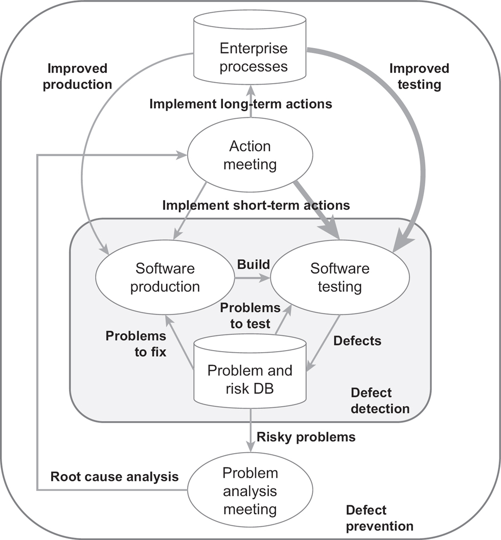
Figure 4.1 shows the defect-prevention cycle (based on IEEE 1044, 2009):
Figure 4.1 Defect prevention cycle (source: IEEE Software Productivity Consortium, extended with test-related improvements)
The efficiency of DP is difficult to measure; however, we have lots of historical data and analysis supporting the usefulness of DP (see Jones and Bonsignour, 2011).
DEFECT PREVENTION METHODS
There are a lot of defect prevention methods. In the following list, we only consider a few of them that are closely connected with test design.
• Model-based testing is a very efficient method for defect prevention. Models are more understandable by testers and developers than any, sometimes unclear and inconsistent, textual specification. Building the right models may help to understand the problem and avoid the use of faulty specifications that often result in faulty test cases.
• Managing complexity by dividing and conquering. Complex things are difficult to handle. Even a small part of a specification may be too complex. If possible, we should divide these parts into manageable portions. A smaller fraction of the specification can be handled more easily by both the testers and the developers. Maintenance of smaller chunks can also be simpler.
• Too many very simple parts may be problematic and unnecessary. Consider an average risky condition. A specification is well-refined if not more than 5-10 abstract test cases are enough to cover it. Note, however, that the complexity and size in any large-scale system have power law distribution, which means that there will always be complex or large cases that cannot be further refined.
• Reviews. Review, Review, Review!
▪ Standard reviews. The most traditional and most common method that has been in use for a long time for defect prevention is review, for example requirements review, design review, code review. There are various types of reviews (see the IEEE 1028:2008 or ISO/IEC 20246:2017 standards), but basically, there are self-reviews and peer-reviews.
▪ Checklist-based reviews. For beginners, a checklist offers a step-by-step process, which is much better to follow than relying entirely on memory to ensure that all steps are covered. The list includes verifications such as:
▪ Is the source information complete, detailed and consistent?
▪ Is the value of the items to be reviewed well understood?
▪ Are the dependencies recognised?
▪ Can the complexity be handled?
▪ Is the test coverage well-defined?
▪ And so on.
• Specification by examples (SBE). These techniques are applied mainly in Agile. They require a team to discuss the specification. This team is usually composed of the three amigos, a tester, a developer and a business analyst. A team with different knowledge and views:
1. reviews the specification very carefully;
2. asks questions and finds incompleteness, ambiguity, controversy and so on;
3. creates examples.
The result is a well-defined specification accepted by every team member and the designed test cases (the examples).
• Implementation-independent test design. The ‘test-first’ point of view is a special case of the divide and conquer approach. Divide producing test cases into two parts: implementation independent (test design), and implementation dependent (test creation). Maintaining implementation-independent test cases is easier and more cost-effective since no modification is needed when the implementation changes. Well-designed implementation-independent test cases can be considered as an extended specification by examples. Based on it, the developers can implement code with much fewer defects.
These types of defect prevention methods should be applied before any test design. However, this is not a completely separate task. Defect prevention and test design require full understanding of the specification. Understanding the specification is a joint activity, and the deeper the understanding of the specification, the more efficient defect prevention and test design can be.
FROM REQUIREMENTS TO SPECIFICATION (‘TWO LIFTS IN A 10-STOREY BUILDING’ EXAMPLE)
In this section we should like to draw attention to the importance of requirements’ feasibility. Approximately half of software faults emerge because of incompleteness, inaccuracy and ambiguities in requirements. Clearly, DP must start with requirements analysis.
Here we begin with some general requirements on an elevator system and at the end we get a refined specification. We demonstrate only one refinement cycle; we skip explaining the inspection, elicitation and analysis parts, as well as the validation. Note that there are processes and techniques on requirements engineering; we refer to Wiegers and Beatty (2013), Cockburn (2001), and Leffingwell (2011).
Part of the following specification will be used later to demonstrate aspects of test design techniques.
Mr Newrich plans to build a 10-storey, many-starred luxury hotel. He thinks that two lifts will be enough to transfer the guests. He obviously does not know much about algorithms and specifications. Basically − regarding the lifts − he has three main requirements, where ‘F’ denotes Functional requirement and CMC denotes Cabin Movement Controlling (System):
F-CMC-1 Every user request should be eventually served if it is not prohibited by emergencies and/or blocked doors. This is the most important requirement.
F-CMC-2 The waiting time and the transferring time should be as minimal as possible, independently of the calling position of the users. This is the second most important requirement.
F-CMC-3 The unnecessary movements of the lifts should be minimised, assuming requirements 1 and 2 hold.
After the first meeting with Mr Newrich, the engineering staff (requirements engineers, lift experts, etc.) reviewed and discussed the possible approaches. They gave Mr Newrich an overview of lift systems (types of lifts, design issues such as cost, speed, capacity requirements, safety, reliability, etc.). They drew attention to the fact that lift users are responsible for operating the lifts according to the safety specifications laid out, and the building owners are responsible for the maintenance of the lifts and for assuring the lifts are compliant before use (via a certificate). The IT staff remarked that in the design, installation and usage a lot of communications have to be done between the various stakeholders, especially with regulators (there are fire regulations, disability acts, design regulations, architectural regulations, etc.). The staff submitted a fourth basic requirement, and the hotel owner accepted it:
F-CMC-4 There will be two types of calling buttons on each level, the ‘Up’ and the ‘Down’; however, on the ground floor only ‘Up’, and on the 10th floor only ‘Down’ will be available. The selected button is displayed.
We can see that these requirements do not involve any implementation details. Of course, we can add more requirements; however, it is not necessary, and for simplicity, we do not do that. Based on these initial requirements the following specification can be given.
Initial specification
The first draft of the specification is the following:
Guests can call the lifts on all floors. If the empty lift is on the same floor as the guest, then the lift door opens (the door of a vacant lift is closed). Guests can call a lift by pressing the button in the desired direction. On the top floor only down, and on the ground floor, only the upward direction is available. If both lifts are empty and a guest calls one, then the closer one starts. If their distance is equal then either of them can start. If the lift moves up or down to a floor where other guests plan to go up or down, then the lift stops and the other empty lift does not start to go to the guests. This means that the lift collects the guests if their moving direction is the same.
If one of the two lifts is moving away from the caller, the empty lift starts for the guest. When a guest enters the lift, they can press the destination. If a guest in the lift presses the opposite direction as outside the lift and other calls are in the original direction, the lift will only go to the desired floor when the other guests have been served.
When a guest calls a lift, the light indicates the desired direction. If the lift arrives, the light goes out. However, if the lift is full and the guest cannot enter the lift, their call remains intact. The lift can measure the weight of the passengers and validate when someone is on board. If the weight does not change, the lift assumes no one has entered, even if a guest left and someone with the same weight boarded. When a lift becomes vacant, and there are registered calls in its memory, then it starts to serve them.
Refined specification
The previous specification has some shortcomings:
• Who presses which button and when?
• What happens when the weight of the guests exceeds the permitted?
• What about emergencies?
• And so on.
The following refinement tries to clarify the deficiencies above. To keep our example simple, we do not detail the following requirements: power system, energy buffers, safety measures, enclosures, dimension, lift entrance measures, door closing time, door opening time, passenger transfer time, speed for normal travel, acceleration time, jerk rate, peak handling capacity time to various destinations, fire services, barrier-free access and so on.
Figure 4.2 shows the basic usage (and actors) of the lift system.
Figure 4.2 Basic usage of the lifts in the ‘Two lifts in a 10-storey building’ example

The lift user is the guest and the lift control system (LCS or controller) is a device that controls the movements of the lifts. Besides the functional (F) requirements we consider only some sample non-functional requirements.
Cabin Request (CR) by user:
F-CR-1 Users can request lifts on each floor via a lift request panel (LR-panel).
F-CR-2 Users can request lifts by selecting the direction they want to go in the LR-panel. On the top floor only ‘Down’ and on the ground floor only the ‘Up’ direction is available.
F-CR-3 User requests are processed by the LCS.
F-CC-1 When the user enters the lift they can select the destination floor in the LC-panel.
F-CC-2 When users press buttons for their desired destinations in the LC-panel inside the cabin, the lift will schedule its movement to those floors.
F-CC-3 When the user selects a destination in alignment with the lift movement, the lift will stop when it arrives at the selected floor; when the user selects a destination opposite to the lift movement, it will not be served until all the requests in alignment with the actual movement are served. Then the lift direction will change and the destination will be served as described.
F-CC-4 When users select the destination floor, it should be highlighted in the LC-panel. When a user presses the ‘Door Open’ or ‘Door Close’ button, the door will react as conditions permit.
F-CC-5 When a user stops the lift (by pushing the Stop button), it ceases its movement.
Cabin Movement Display (CMD) System:
F-CMD-1 When a user requests a lift (by pushing the button ‘Up’ or ‘Down’ or both in the LR-panel) the required direction will be displayed.
F-CMD-2 If a lift stops at a floor, and a guest enters the lift (measured by weight change), the display of its next movement direction is switched off (if it was on) in the LR-panel and the system sends a message to the LCS that the guest request has been satisfied.
F-CMD-3 If no guest enters when a lift stops for them, then the display is switched off, and the system sends a message to the LCS that the guest request has been satisfied.
F-CMD-4 When a lift stops at a level, then the direction of the next movement is displayed (there are four possibilities, None, Up, Down, Up/Down).
Cabin Movement Controlling (CMC) System:
F-CMD-1 If both lifts are vacant and a user requests one, then always the closer lift will start to the caller’s direction. In the case of equality, Lift-1 is chosen.
F-CMD-2 If one of the lifts is vacant and the other one is moving then the vacant one starts for them.
F-CMD-3 When no lift is available then the user request is scheduled.
F-CMD-4 When a lift becomes vacant, the oldest pending request must be handled first.
F-CMD-5 The lift measures the weight of the passengers and validates when someone is on board.
F-CMD-6 The lift does not start when it is overloaded. In this case, a safety message is displayed to the user.
F-CMD-7 The serving order depends on the location of the lifts, on their moving directions and on their request queues.
F-CMD-8 The non-empty lift stops for users when an up/down call is received from them while the lift is moving up or down as well, and is approaching the user.
Example: Empty Lift-1 is standing at floor 2. Non-empty Lift-2 is moving from floor 6 downwards to the ground floor. At present it is between floors 5 and 4. Then, there is a down call on floor 3 and an up call on floor 1. Lift-2 will stop at floor 3 and pick up the passengers. It does not stop at the first floor. Lift-1 starts to pick up the passengers in floor 1.
F-CMD-9 The empty lift goes for the user first in the queue and does not stop for other users.
Some non-functional (NF) emergency requirements:
NF-1 The buttons for the lift request system (Up/Down) must be distinguishable.
NF-2 The buttons for the lift control system (Floors, Door Open/Close, Start/Stop) should be easy to use.
NF-3 When the lift’s travelling plan is empty, but the lift is not empty (meaning that somebody is in the lift), after a certain timeout an emergency sign will be sent to the dispatcher.
The Cabin Movement Controlling System gets messages from the users when they push some buttons in the LR-panel. The CMC also gets messages when the requests are satisfied. The task of the CMC is to control the travelling plans of the lifts.
We can see that after the refinement, the specification is more structured, much clearer and more complete. We suggest the reader validate the requirements by examining the following attributes: necessity, completeness, correctness, unambiguity, technical availability, verifiability and implementation independence (see Pohl and Rupp, 2016). Based on good requirements both the test design and the implemented code will be better.
REFINEMENT OF THE TICKET VENDING MACHINE SPECIFICATION
In this section, we apply the defect prevention based on SBE. In Chapter 2 we gave a specification of the ticket vending machine. Both authors reviewed this and believed it was OK. Later on, they organised an Agile meeting including a developer whose task was the implementation of the TVM. One of the authors read one bullet point at a time, and the team tried to find bugs in the specification. In the case of an issue, the team discussed it and made a decision based on consensus. A significant number of issues were found:
1. Ticket prices may change; the text omits any reference to it.
2. In some places, the text contains implementation-related elements (‘Reset’ button, ‘+’, ‘-’).
3. Payment is only possible if the number of selected tickets is greater than zero.
4. It can happen that the machine does not operate properly and there is no error message. The requirements description should also include these cases.
5. The time limit should also be considered during the money insertion phase.
We improved the specification as follows. New text in the specifications is denoted by italics; the deleted text by ‘deletedtext’:
The ticket vending machine is a vending machine that produces tickets. The typical transaction consists of a user using the display interface to select the type and quantity of tickets. After successful payment, the ticket or tickets are printed and dispensed to the user.
• Ticket types. There are three types of tickets:
a. standard ticket valid for 75 minutes on any metro, tram or bus line;
b. short-distance ticket valid within five stations on a single line of any metro, tram or bus;
c. 24-hour ticket for unlimited metro, bus, and train travel for 24 hours from validation.
The price of the tickets can only be modified by the system administrator of the TVM company. It is impossible for any users to modify the prices. Currently (a) is EUR 2.10, (b) is EUR 1.40 and (c) is EUR 7.60.
• Initial screen: Coins to be accepted: 5c, 10c, 20c, 50c, €1, €2. Banknotes to be accepted: €5, €10, €20 and €50. Initially, the three types of tickets are shown with the quantity to be bought, which is at the beginning set to 0. A ‘Reset’ button is also found on the screen by which the number of tickets can be reset to 0. Buttons ‘+’ and ‘-‘are beside the ticket types for increasing and decreasing the number of tickets to be purchased. The number of tickets can be reset to 0 at any time.
• Selecting tickets. The customer can buy tickets of one type only. If all the amounts of the tickets are zero, then any of them can be increased. After that, the ticket type with the non-zero number can be increased or decreased by clicking on ‘+’ or ‘-‘. The maximum number of tickets to be chosen is 10. ‘+’ and ‘-‘ are unavailable when the number of tickets is 10 or 0, respectively. The customer can increase the number of tickets to be purchased by one up to 10. The customer can reduce the number of tickets to be purchased by one but not below 0. If the selected amount of tickets is greater than 0, then the buying process can start.
• Buying process. Payment is possible if the customer has selected at least one ticket. Payment is made by inserting coins or banknotes. The ticket machine always shows the remaining amount necessary for the transaction. For the remaining amount to be paid, the machine only accepts those banknotes for which the selection of the smaller banknote does not reach the required amount. €5 is always accepted. For example, if the necessary amount is EUR 21, then the machine accepts €50 since EUR 20 will not exceed EUR 21. If the user inserts €10 and then €2, then even €20 is not accepted since the remaining amount is EUR 9; EUR 10 would exceed the necessary amount. The remaining amount and currently acceptable banknotes are visible on the screen. If the user inserts a non-acceptable banknote, then it will be given back, and an error message will appear notifying the user of the error.
• Successful transaction. The ticket machine always shows the remaining amount necessary for the transaction, which is successful if the inserted money reaches or exceeds the required amount. In the latter case, the difference is given back to the user. After payment, the tickets are printed.
• Inactivity. After 20 seconds of inactivity, the initial screen appears again and the previous ticket selection has been cancelled. If money has been inserted and nothing happens for 20 seconds, the money the customer put in is returned and the start screen is displayed.
• Delete selection and error handling. The transaction can be cancelled at any time before finishing the payment. In this case, all the inserted money is given back. The situation is similar to when something goes wrong, that is all the inserted money is given back. In the case of an error the ticket machine state will be ‘faulty’, and the start screen will appear with an error message. If the TVM goes wrong, then any inserted money should be given back. If this does not happen, the customer can get the money from the TVM company in another way.
• Reduced mode. If there is a chance that the ticket machine cannot return the money exceeding the ticket price (which process is specified by a third party algorithm), then the machine will go into ‘Reduced mode’. In this case, only those coins and banknotes will be accepted that do not result in the amount inserted exceeding the required amount. The status ‘reduced’ will be visible on the screen. The largest usable banknote is displayed.
▪ (Other issues. It can happen that the machine does not operate properly and there is no error message. For example, the user’s inserted money is absorbed. The TVM must know this amount. This money must be returned; the complaint can be made by the customer via telephone. To keep our example simple, the testing of this part is not covered by our book.)
With this improvement, the specification became more precise, lowering the probability of bugs due to the incomplete specification. Our defect prevention work has been done successfully.
In this book, we will use parts of these specifications in various examples to present the various testing techniques.
• Use defect prevention to improve quality and decrease costs.
• Specifications and user stories are almost always incomplete and ambivalent – this can be fixed by different DP methods such as:
▪ SBE;
▪ review techniques;
▪ reducing complexity;
▪ model-based testing.
• Similarly to risk analysis, DP is a pre-test design activity which cannot be neglected.