CHAPTER 14
Personal Computer Audio
Early personal computers were little more than programmable calculators, with almost no audio capabilities. A PC typically contained a tiny speaker that was used to emit prompt beeps. The idea of making music was virtually improbable. In one celebrated demonstration, an early enthusiast programmed his computer so that when an AM radio was placed nearby, the interference from the meticulously programmed digital circuits produced rhythmic static in the radio that, in the broadest sense of the word, could be interpreted as the musical theme from Rossini’s William Tell overture.
With the advent of more powerful hardware and software, personal computers became more adept at making music. In particular, audio chip sets became staples in PCs. Containing synthesis chips and A/D and D/A converters, these systems are used to play MIDI files, sound effects, and to record and play back WAV files. Simultaneously, CD-ROM and DVD-ROM drives became common, and are used to play audio CDs as well as DVD-Video movies. Multichannel speakers and subwoofers are common accessories in the PC market. The PC industry has adopted audio technologies such as the CD, DVD, Blu-ray, 3D audio, and sound synthesis, and contributed computer technologies such as the PCI bus, Win98, MMX, AC ‘97, IEEE 1394, and USB. These individually diverse improvements allow an integration of technologies, and bring a new level of fidelity and features to PC digital audio and multimedia in general. Moreover, the personal computer has become the nucleus of both professional and personal recording studios in a wide variety of applications.
PC Buses and Interfaces
Internal and external peripherals can be interfaced to a host computer with any of several interconnections. IBM-PC computers historically contained the ISA (Industry Standard Architecture) local bus; its 11-Mbyte/second transfer rate limits audio applications. A stereo CD data stream, at 1.4 Mbps, along with sound effects and several voices might consume 40% of the bus, leaving little capacity for the multitasking operating system. The EISA (Extended ISA) local bus offers a 32-Mbyte/second rate and other improvements, but is also limited for audio applications. The PCI (Peripheral Component Interconnect) is a high-performance local interconnection bus. PCI provides a maximum 132-Mbyte/second transfer rate, 32-bit pathways, good noise immunity, and efficiently integrates the computer’s processor and memory with peripherals. The PCI bus is lightly taxed with even multiple audio streams. Moreover, the PCI bus outperforms the ISA and EISA bus in terms of latency. An audio output must be free of any interruptions in the flow of audio data. Because of its high performance, the PCI bus allows cooperative signal processing in which tasks are balanced between the host processor and an audio accelerator. For these and other reasons, the PCI bus replaced the ISA bus. Microsoft’s PC98 specification decreed that new logos would no longer be issued to ISA audio products. The PCI bus is found on both Macintosh and IBM-PC computers.
The ATA (Advanced Technology Attachment) bus was designed as the expansion slot format for the PC providing a 16-bit path width and burst speeds up to 8.3 Mbyte/second; it is also known as the IDE (Integrated Drive Electronics) bus. Faster variants include EIDE (Enhanced Integrated Drive Electronics) or ATA-2 and Ultra ATA (ATA-3 or Ultra DMA). ATA-2 accommodates burst speeds up to 16 Mbytes/second, and ATA-3 accommodates speeds up to 33.3 Mbytes/second. The PCMCIA (Personal Computer Memory Card International Association) is used on notebook computer expansion ports.
Some computers use SCSI (Small Computer System Interface) connections. SCSI (pronounced “scuzzy”) is a high-speed data transfer protocol that allows multiple devices to access information over a common parallel bus. Transmitting (smart) devices initiate SCSI commands; for example, to send or request information from a remote device. Likewise, receiving (dumb) devices accept SCSI commands; for example, a hard disk can only receive commands. Some devices (sometimes called logical devices) are classified as transmitter/receivers; computers are grouped in this category.
The SCSI protocol allows numerous devices to be daisy-chained together; each device is given a unique identification number; numbers can follow any order in the physical chain. A SCSI cable can extend to 12 meters. A device must have two SCSI ports to allow chaining; otherwise, the device must fall at the end of the chain. Generally, the first and last physical devices (determined physically, not by identification number) in a chain must be terminated; intermediate devices should not be terminated. Termination can be internal or external; devices that are externally terminated allow greater liberty of placement in the chain.
SCSI defines a number of variants, differing principally in data path width and speed, as well as physical connectors. The basic SCSI-1 width (number of bits in the parallel data path) is 8 bits (narrow). In addition, 16-bit (wide) and 32-bit (very wide) versions are used. The basic SCSI-1 data transmission rate is 12.8 Mbps, that is, 1.6 Mbyte/second; all data transfer is asynchronous. Other speeds include Fast, Ultra, Ultra 2, and Ultra 3. For example, Ultra 2 can accommodate transfers of up to 80 Mbyte/second. Narrow SCSI devices use 50-pin connectors, and wide devices use 68-pin connectors.
Alternatively, the Enhanced-IDE/ATAPI interface can be used to connect computers and peripherals at speeds of 13.3 Mbyte/second over short (18 inch) cables. Fast ADA-2 hard-drive interfaces can operate at 16.6 Mbyte/second. However, unlike SCSI, these are simple interfaces that do not support intelligent multitasking. To overcome many interconnection installation problems in PCs, the Plug and Play standard was devised. The operating system and system BIOS automatically configure jumper, IRQ, DMA address, SCSI IDs, and other parameters for the plug-in device. Many DVD-ROM drives use E-IDE/ATAPI or SCSI-2 interfaces. The SFF 8090i Mt. Fuji standard allows the ATAPI and SCSI interfaces to fully support DVD reading of regional codes, decryption authentication, CSS and CPRM data, BCA area, and physical format information.
IEEE 1394 (FireWire)
The Institute of Electrical and Electronics Engineers (IEEE) commissioned a technical working group to design a new data bus transmission protocol. Based on the FireWire protocol devised by Apple Computer, the IEEE 1394-1995 High Performance Serial Bus standard defines the physical layer and controller for both a backplane bus and a serial data bus that allows inexpensive, general purpose, high-speed data transfer; the latter is discussed here. The IEEE 1394 cable bus is a universal, platform-independent digital interface that can connect digital devices such as personal computers, audio and video products for multimedia, digital cable boxes and HDTV tuners, printer and scanner products, digital video cameras, displays, and other devices that require high-speed data transfer. For example, a digital camcorder can be connected to a personal computer for transferring video/audio data. Wireless Fire Wire technology has also been developed, using IEEE 802.15.3 technology.
The IEEE 1394 cable standard defines three data rates: 98.304, 196.608, and 393.216 Mbps. These rates are rounded to 100, 200, and 400 Mbps, and are referred to as S100, S200, and S400. The latter is also known as FireWire 400. These rates permit transport, for example, of 65, 130, and 260 channels of 24-bit audio, sampled at 48 kHz. The IEEE 1394b standard enables rates from 800 Mbps to 3.2 Gbps. More details of IEEE 1394b are given below. The 1394c standard merges FireWire and Ethernet technologies.
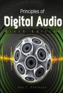
The IEEE 1394 connecting cable is thin (slightly thicker than a phone cable) and uses copper wires; there are two separately shielded twisted-pair transmission lines for signaling, two power conductors, and a shield. A four-conductor version of the standard cable with no power connectors is used in some consumer audio/video components. It is defined in IEEE 1394.1 and is sometimes known as i.Link. (IEEE 1394, FireWire and i.Link are all functionally equivalent and compatible.) The two twisted pairs are crossed in each cable assembly to form a two-way transmit-receive connection. The IEEE 1394 connector (the same on both cable ends) is small and rugged (and derived from Nintendo’s GameBoy connector). It uses either a standard friction detent or a special side-locking tab restraint, as shown in Fig. 14.1. Since it can deliver electrical power (8 to 40 volts, up to 1.5 amperes), an IEEE 1394 cable can be used as the sole connecting cable to some devices. It is similar to a SCSI cable in that it can be used as a point-to-point connection between two devices, or devices can be connected with branches or daisy-chained along lengths of cable. However, unlike SCSI, no addressing (device ID) or termination is needed. In some cases, IEEE 1394 is used with other cabling such as Category 5 twisted pair and optical fiber. With 50-mm multimode fiber, for example, cable runs of hundreds of meters are permitted. However, more robust clocking methods are required.
A cable can run for 4.5 meters between two devices without a repeater box (this length is called a hop) and there may be up to 16 cable hops in a line, extending a total distance of up to 72 meters with standard cable (longer distances are possible with higher quality cable). Up to 63 devices can be directly connected into a local cluster before a bus bridge is required, and up to 1023 clusters can be connected via data bridges. IEEE 1394 can be used equally well to connect two components or run throughout an entire home or office to interconnect electronic appliances. IEEE 1394 is “hot-pluggable” so that users can add or remove devices from a powered bus. It is also a scalable architecture, so users can mix multiple speed devices on one bus.
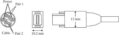
FIGURE 14.1 The IEEE 1394 connector (the same on both cable ends) forms a two-way transmit-receive connection carrying two twisted-pair signal cables, and power.
IEEE 1394 defines three layers: physical, link, and transaction. The physical layer defines the signals required by the IEEE 1394 bus. The link layer formats raw data (from the physical layer) into recognizable IEEE 1394 packets. The transaction layer presents packets (from the link layer) to the application.
The IEEE 1394 bus data rate is governed by the slowest active node. However, the bus can support multiple signaling speeds between individual node pairs. Considering that the rate of a stereo digital audio bitstream may be 1.4 Mbps, a compressed video stream may also be 1.4 Mbps, and an uncompressed broadcast-quality video stream may be 200 Mbps, an IEEE 1394 interface can accommodate multimedia data loads.
When a connection is made, the bus automatically reinitializes the entire bus, recognizing the new device and integrating it with other networked devices, in less than 125 μs. Similarly, upon disconnection, IEEE 1394 automatically reconfigures itself. Asynchronous transmission performs simple data transfers. As with all asynchronous transmission, a chunk of data is transferred after acknowledgement that a previously transmitted chunk has been received. Since this timing cannot be predicted because of other network demands, timing of delivery is random; this is problematic for real-time audio and video data.
Real-time, data-intensive applications such as uncompressed digital video can be provided bandwidth and low latency, using isochronous transmission. With isochronous transmission, synchronized data such as audio and video will be conveyed with sufficiently small discrepancy so that they can be synchronized at the output. Instead of a send/acknowledgement method, isochronous transmission guarantees bus bandwidth for a device. Nodes request a bandwidth allocation and the isochronous resource manager uses a Bandwidth Available register to monitor the bandwidth available to all isochronous nodes. All bus data is transmitted in 32-bit words called quadlets and bandwidth is measured in bandwidth allocation units. A unit is about 20 ns, the time required to send one data quadlet at 1600 Mbps. The isochronous resource manager uses its Channels Available register to assign a channel number (0 to 63) to a node requesting isochronous bandwidth. This channel number identifies all isochronous packets. When a node completes its isochronous transfer, it releases its bandwidth and channel number. A bus manager such as a PC is not needed; any “talker” device can act as the isochronous resource manager to create a single, fixed isochronous channel.
Using the common timebase of isochronous transmission, data packets can be encoded with a small equalizing time delay, so the output is exactly synchronized with the clock source—a critical feature for audio and video data words that must arrive in order and on time. This feature is particularly crucial when an IEEE 1394 cable is handling simultaneous transmissions between different devices. Isochronous transmissions are given priority status in the time-multiplexed data stream so that an audio and video transfer, for example, is not disrupted by a control command. Whereas some interfaces are expensive because large memory buffers are needed to temporarily store data at either cable end, IEEE 1394 does not need large buffers. Its just-in-time data delivery allows devices to exchange data or commands directly between their internal memories.
The IEEE 1394 specification includes an “Audio and Music Data Transmission Protocol” (known as the A/M protocol) that defines how real-time digital audio can be conveyed over IEEE 1394 using isochronous packets. Data types include IEC-958 and raw audio samples (in data fields up to 24-bits in length) as well as MIDI files (with up to 3 bytes per field); it is standardized as IEC 61883-1/FDIS. This protocol, and multi-channel versions, provide sufficient bandwidth to convey DVD-Audio data streams of 9.6 Mbps. Copy-protection methods are used to guard against piracy of these high-quality DVD-Audio signals.
The mLAN specification can be used to send multiple sample-accurate AES3 signals, raw audio, MIDI, and other control information over an IEEE 1394 bus. The mLAN protocol uses an isochronous transfer mode that ensures on-time delivery and also prevents collisions and reduces latency and jitter. The specification reduces jitter to 20 ns, and when phase-locked loops are used at individual mLAN nodes, jitter can be further reduced to 1 ns. Up to 63 devices can be connected in any topology, ports are hot-pluggable and software patching is routinely used. A portion of mLAN was adopted by the 1394 Trade Association as a supplemental standard for handling audio and music control data over the IEEE 1394 bus. mLAN was developed by Yamaha Corporation.
The first implementations of the 1394b standard, with throughput of 800 Mbps and 1600 Mbps, are also known as S800 and S1600. IEEE 1394b allows daisy-chaining of multiple peripherals. It also allows cable lengths of up to 800 meters for networks using twisted pair CAT-5 and plastic optical fiber. The Bus Owner Supervisor/Selector (BOSS) protocol allows data packets to be transmitted more efficiently, using less network bandwidth. IEEE 1394b ports use a different physical configuration than 1394; adapter cables are needed for compatibility.
IEEE 1394 is a non-proprietary standard and many standards organizations and companies have endorsed the standard. The Digital VCR Conference selected IEEE 1394 as its standard digital interface. An EIA subcommittee selected IEEE 1394 as the point-to-point interface for digital TV as well as the multi-point interface for entertainment systems. Video Electronics Standards Association (VESA) adopted IEEE 1394 for home networking. The European Digital Video Broadcasters also endorsed IEEE 1394 as their digital television interface. Microsoft first supported IEEE 1394 in the Windows 98 operating system, and it is supported in newer operating systems. IEEE 1394 was first supported by the Macintosh operating system in 1997; Apple Computer supports IEEE 1394 on its computer motherboards.
IEEE 1394 may appear in PCs, satellite receivers, camcorders, stereos, VCRs, printers, hard drives, scanners, digital cameras, set-top boxes, music keyboards and synthesizers, cable modems, CD-ROM drives, DVD players, DTV decoders, and monitors. In some applications, such as when connecting to displays, Digital Transmission Content Protection (DTCP) technology is used to encrypt data, allowing secure, two-way transmission of digital content across an IEEE 1394 interface.
Digital Transmission Content Protection (DTCP)
The security of transmitted data is an important issue in many applications. The Digital Transmission Content Protection (DTCP) system was devised for secure (anti-piracy) transmission in the home environment over bi-directional digital lines such as the IEEE 1394 bus. Sometimes known as “5C,” it was devised by a consortium of companies including Sony, Toshiba, Intel, Hitachi, and Matsushita, as well as the Motion Picture Association of America. DTCP prevents unauthorized copying of digital content while allowing legitimate copying for purposes such as time-shifting. Connected devices trade keys and authentication data, the transmitting device encrypts the signal, and the receiving device decrypts it. Devices such as video displays identify themselves as playback-only devices and can receive all data. Recorders can only receive data marked as copy-permitted, and must update and pass along Copy Control Information (CCI). DTCP does not affect other copy protection methods that may be employed on DVD or Blu-ray discs, satellite broadcasts, and so on. DTCP uses encryption on each digital link. Each device on a link obeys embedded CCI that specifies permitted uses of content: Copy-Never (no copies allowed, display only), Copy-One-Generation (one copy allowed), Copy-No-More (prevents making copies of copies), and Copy-Freely (no copy restrictions). Two-way “challenge and response” communication provided by the Authentication and Key Exchange system enables source components in the home to confirm the authenticity of receiving components.
DTCP can revoke the privileges of rogue equipment attempting to defeat the system, obtain encryption keys, and so on. To do this, each piece of consumer equipment contains System Renewability Messages (SRMs), a list of serial numbers of individual pieces of equipment used in piracy. SRMs are updated through packaged software, transmissions, and new equipment, and are automatically passed along to other components. Source components re-encrypt data to be transmitted to receiving components; encryption keys are changed as often as every 30 seconds. The Digital Transmission Licensing Administrator (DTLA) was established to license the content-protection system and to generate and distribute cryptographic materials such as keys and certificates. DTCP is designed for use in HDTV receivers, set-top boxes, digital recorders, satellite receivers, and other consumer components. Encryption and water-marking are discussed in Chap. 15.
Universal Serial Bus (USB)
The Universal Serial Bus (USB) was designed to replace older computer serial (and parallel) I/O buses, to provide a faster, more user-friendly interconnection method, and to overcome the limitation of too-few free interrupts available for peripherals. Computer keyboards, mice, cable modems, telephones, ROM drives, flash memories, printers, scanners, digital cameras, multimedia game equipment, MIDI devices, and loudspeakers are all candidates for USB. Unlike IEEE 1394, which permits interconnection between any two enabled devices, USB requires a microprocessor-based controller, and hence it is used primarily for PC peripherals. A few USB ports can replace disparate back-panel connectors.
The original USB specification, known as USB 1.1, provides low-speed interconnection. The newer USB 2.0 specification (sometimes known as “Hi-Speed USB”) provides data rates that are 40-times faster than USB 1.1. The USB 1.1 specification provides a transfer rate of 12 Mbps (about 1 Mbps of this is used for overhead). This transfer rate is sufficient for applications employing S/PDIF, AC-3, and MPEG-1, as well as some MPEG-2 applications. There is also a 1.5-Mbps subchannel available for low data-rate devices, such as a mouse. USB 2.0 offers transfer rates up to 480 Mbps. This allows connection to high-speed ROM drives and in particular allows rapid transfer of large video files. USB 2.0 is fully compatible with 1.1 devices; however, 1.1 devices cannot operate at the faster speed. USB 2.0 uses the same connectors and cables as USB 1.1.
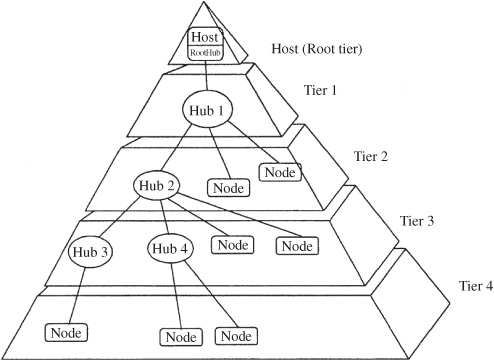
FIGURE 14.2 The USB interconnect uses a tiered-star topology, with a hub at the center of each star. Each cable forms a point-to-point connection between the host and a hub or function, or a hub connected to another hub or function.
USB is SCSI-like in its ability to support up to 127 devices per port/host in a plug-and-play fashion. Moreover, USB devices can be hot-swapped without powering down the system. USB detects when a device is added or withdrawn, and automatically reinitializes the system. USB uses a tiered star topology in which only one device, such as a monitor or DVD-ROM drive, must be plugged into the PC’s host (root) connector, as shown in Fig. 14.2. There is only one host in any system. It becomes a hub and additional devices can be connected directly to that hub or to additional hubs, using cable runs of 5 meters (full-speed devices) and 3 meters (low-speed devices). The host polls connected devices and initiates all data transfers.
USB hubs may be embedded in peripheral devices or exist as stand-alone hubs. Hubs contain an upstream connection port (pointed toward the PC) as well as multiple downstream ports to connect peripheral devices. USB uses a four-wire connector; a single twisted pair carries bidirectional data (one direction per wire), and there are 5-V power and ground conductors to deliver electrical power to low-power (500 mA, or 100 mA for a bus-powered hub) peripheral devices. The typical detachable cable is known as an “A to B” cable. “A” plugs are always oriented upstream toward the host (“A” receptacles are downstream outputs from the host or hub). “B” plugs are always oriented downstream toward the USB device (“B” receptacles are upstream inputs to the device or hub). An “A” and “B” cable assembly is shown in Fig. 14.3. All detachable cables must be full-speed.
USB host controllers manage the driver software and bandwidth required by each peripheral connected to the bus, and allocate electrical power to USB devices. Both USB host controllers and USB hubs can detect attachments and detachments (for device identification and dynamic reconfiguration) of peripherals using biased termination at cable ends. Hubs are required for multiple connections to the host connector. All devices have an upstream connection; hubs include downstream connections. Upstream and downstream connectors are polarized to prevent loop-back. Hubs can have up to seven connectors to nodes or other hubs, and may be self-powered or powered by the host. Two PCs can be connected to each other with a specialized USB peripheral known as a USB bridge (sometimes called a USB-to-USB adapter). A direct PC-to-PC connection using an illegal “A to A” cable could short the two PCs’ power supplies together, creating a fire hazard.
FIGURE 14.3 Physical specifications for the USB detachable cable. “A” plugs orient upstream toward the host and “B” plugs orient downstream. The cable carries one twisted-pair cable, and power.
The USB On-the-Go (USB OTG) supplement to the USB specification is used for portable devices such as cell phones and digital cameras. It allows limited hosting capabilities for direct point-to-point communication with selected peripherals. Devices can be either a host or peripheral and can dynamically switch roles. In addition, a smaller connector and low-power features are implemented. USB OTG is designed to supplant the many proprietary connections used in docking stations and slot connectors. USB OTG devices are compliant with the USB 2.0 specification.
USB is well-suited for transport of audio signals. Standardized audio transport mechanisms are used to minimize software driver complexity. A robust synchronization scheme for isochronous transfers is incorporated in the USB specification. In particular, USB provides asynchronous transfer, but isochronous transfer is used for relatively higher-bandwidth (audio and video) devices. Isochronous transfer yields low jitter but increased latency. The transfer rate for a 16-bit, 48-kHz stereo signal is 192 bytes/ms. To maintain a correct phase relationship between physical audio channels, an audio function is required to report its internal delay to every audio streaming interface. The delay is expressed in number of frames (ms) and is caused by the need to buffer frames to remove packet jitter and by some audio functions that introduce additional delay (in integer numbers of frames) as they interpret and process audio streams. Host software uses delay information to synchronize different audio streams by scheduling correct packet timings. Phase jitter is limited to ±1 audio sample.
USB has many practical audio applications. For example, USB allows designers to bypass potentially poor D/A converters on motherboards and sound cards, and instead use converters in the peripheral device. For example, USB loudspeakers have D/A converters and power amplifiers built-in, so the speaker can receive a digital signal from the computer. USB loudspeakers obviate the need for sound cards in many implementations, and simplify the connection of PCs to outboard converters, digital signal processors, Dolby Digital decoders, and other peripherals.
Sound Card and Motherboard Audio
Most computer motherboards and sound cards contain A/D and D/A converters and hardware- and software-based processing to permit recording and playback of stereo 8- or 16-bit audio at multiple sampling rates. They also allow playback via wavetable synthesis, sampled sound, or FM synthesis. They provide digital I/O; ROM drive interfaces; a software-controlled audio mixer; onboard power amplifiers; and may also provide analog line-in and line-out, S/PDIF input and output, microphone input, and a gamepad/joystick/MIDI connector. Sound cards plug into an expansion slot and are accompanied by the appropriate software that is bundled with the card. The most basic part of the software regimen is the device drivers needed to control the various audio components.
Sound synthesis capabilities are used to create sound effects when playing MIDI files or playing video games. A sampled sound synthesizer plays stored sound files—for example, SND or AIFF (Audio Interchange File Format) files. Most chip sets support sample-based wavetable synthesis; this allows synthesis and playback of both music and sound effects via software. With wavetable synthesis, a particular waveform is stored in ROM, and looped through to create a continuous sound. Some audio chip sets support physical model-based waveguide synthesis in which mathematical models are used to emulate musical instrument sounds. In terms of synthesis ability, a chip may support 128 wavetable instruments, with many variation sounds and multiple drum sets using onboard RAM. Moreover, 64 voices may be supported, with multi-timbral capability on 16 channels. Most chips have a MIDI interface for connection to an external MIDI hardware instrument such as a keyboard. A chip set may also contain built-in 3D stereo enhancement circuitry. These proprietary systems, in greater or lesser degrees, increase depth and breadth of the stereo soundstage, and broaden the “sweet spot” where channel separation is perceived by the listener. Some chip sets include a DSP chip that allows hardware data reduction during recording and playback, and others provide resident non-real-time software data reduction algorithms. In addition, some chips provide voice recognition capability. These topics are discussed in more detail below.
Music Synthesis
From their origins as simple MIDI synthesizers employing FM synthesis, computer sound systems have grown in complexity. Diverse synthesis methods are employed, and the quality of rendered music varies dramatically with the type of synthesizer hardware installed. Many synthesizers generate audio signals from a file consisting of a table of audio samples. Traditionally, these tables are filled with single cycles of simple basis waveforms such as sinusoids or triangle waves. Complex sounds are generated by dynamically mixing the simple signals using more sophisticated algorithms. This is known as traditional wavetable synthesis. During playback, a pointer loops through the table continuously reading samples and sending them to a D/A converter. Different pitches are obtained by changing the rate at which the table is read. For higher pitches, the processor skips samples; for example, to double the frequency, every other sample is read. Noninteger higher pitches are accomplished by skipping samples and interpolating new values. For lower pitches, the processor adds samples by interpolating values in-between those in the table. In both cases, the sample rate at the D/A converter remains constant. By dynamically mixing or crossfading different basis waveforms, complex sounds can be generated with low data storage overhead; a table may be only 512 samples in length.
Sample-based synthesis uses short recordings of musical instruments and other natural sounds for the basis waveforms. However, instead of perhaps 512 samples per table, these synthesizers may use thousands of samples per table. Because musical events may last several seconds or more, considerable memory would be required. However, most musical events consist of an attack transient followed by a steady-state sustain and decay. Therefore, only the transient portion and a small section of the steady-state portion need to be stored. Sound is created by reading out the transient, then setting up a wavetable-like loop through the steady-state section.
Because sample-based synthesis also uses wave lookup tables, the term “wavetable synthesis” became synonymous with both technologies and the two terms are used interchangeably. However, contemporary “wavetable synthesis” chips are really sample-based instruments. The quality of the synthesis depends on the quality of the initial recording, size of the table, and location of the loop points. Short, low-resolution tables produce poor quality tones. Although a sound card may claim “CD-quality,” table resolution may only be 8, 12, or 14 bits, and not the 16-bit CD standard.
In physical modeling synthesis, the sound of a vibrating system (such as a musical instrument) is created using an analogous software model. For example, a plucked string vibrates as transverse waves propagating along the length of a string. The vibrations decay as the waves lose energy. A string model might consist of an impulse, traveling through a circular delay line (or memory buffer), with its output connected back to the input through an attenuator and filter. The filtering and attenuation cause the impulse to simultaneously decay in amplitude and become more sinusoidal in nature, emulating a vibrating string. The length of the buffer controls pitch, and the filter and attenuator provide the correct timbre and decay. Physical modeling is attractive because it is easily implemented in software. It can produce consistent results on different computers, and the coded algorithms are quite short; however, relatively fast processors are needed to synthesize sound in real time.
In pure software synthesis, sounds are created entirely on the host computer, rather than in a dedicated sound chip. Software synthesizers can be distributed on disc or as downloadable files. Some downloadable software synthesizers are available as browser plug-ins for network applications.
Surround Sound Processing
Stereo playback can convey a traditional concert soundstage in which the sound comes mainly from the front. However, stereo signals cannot convey ambient sounds that come from all around the listener. Stereo’s lack of spatiality undermines sonic realism, for example, in a game where aircraft fly overhead from front to back. The lack of spatiality is exacerbated by the narrow separation between speakers in most PC playback systems. To provide a more convincing sound field, various algorithms can modify stereo signals so that sound played over two speakers can seem to come from around the listener. Alternatively, adequately equipped PCs can convey discrete 5.1-channel playback.
Stereo surround sound programs process stereo signals to enlarge the perceived ambient field. Other 3D positioning programs seek to place sounds in particular locations. Psychoacoustic cues such as interaural time delays and interaural intensity differences are used to replicate the way sources would sound if they were actually in a 360-degree space. This processing often uses a head-related transfer function (HRTF) to calculate the sound heard at the listener’s ears relative to the spatial coordinates of the sound’s origin. When these time, intensity, and timbral differences are applied to the stereo signal, the ear interprets them as real spatial cues, and localizes the sound outside the stereo panorama. These systems can process sound during real-time playback, without any prior encoding, to position sound statically or dynamically. Results differ, but are generally quite good if the listener is seated exactly between the speakers—the ergonomic norm for most PC users. In some cases, the surround process must be encoded in the source media itself. There are a wide variety of 3D audio plug-in and chip options from numerous companies. Surround programs written for DirectSound contain compatible positioning information required by the spatial positioning programs.
Home theater systems employ 5.1-channel playback with left and right front channels, center front channel, left and right rear channels, and a low-frequency effects channel. Dolby Digital (also known as AC-3) and DTS both employ 5.1-channel processing. Dolby Digital was selected as the audio coding method for DVD-Video, as well as DTV; Dolby Digital and DTS are used in the Blu-ray format. Dolby Digital and DTS are described in Chap. 11. Many PCs can play back 5.1-channel audio tracks on both movie and game titles. Similarly, with DTV tuners, PCs can play back 5.1-channel broadcasts; 5.1 playback is the norm for home media PCs.
Although 5.1-channel playback improves realism, it presents the practical problem of arraying six loudspeakers around a PC. Thus, a number of surround synthesis algorithms have been developed to specifically replay multichannel formats such as Dolby Digital over two speakers, creating “virtual speakers” to convey the correct spatial sense. This multichannel virtualization processing is similar to that developed for surround synthesis. Dolby Laboratories grants a Virtual Dolby certification for both the Dolby Digital and ProLogic processes. Although not as realistic as physical speakers, virtual speakers can provide good sound localization around the PC listener.
Audio Codec ’97 (AC ’97)
The Audio Codec ’97 (AC ’97) component specification (also known as MC ’97 or Modem Codec ’97) describes a two-chip partitioned architecture that provides high-quality PC audio features. It is used in motherboards, modems, and sound cards. High-speed PC buses and clocks, and digital grounds and the electromagnetic noise they radiate, are anathema to high-quality audio. With legacy systems, integrated hardware is placed on the ISA bus so that analog audio circuitry is consolidated with digitally intensive bus interfaces and digital synthesizer circuits, resulting in audio signal degradation. The Audio Codec ’97 specification segregates the digital portion of the audio system from the analog portion. AC ’97 calls for a digital chip (with control and processing such as equalization, reverberation, and mixing) on the bus itself, and an analog chip (for interfacing and conversion) off the bus and near the I/O connectors. AC ’97 supports all Windows drivers and bus extensions. AC ’97 is also backward-compatible with legacy ISA applications.
The AC ’97 specification defines the baseline functionality of an analog I/O chip and the digital interface of a controller chip. The analog chip is purposefully small (48-pins) so that it can be placed near the audio input and output connectors, and away from digital buses. The larger (64-pin) digital controller chip can be located near the CPU or system bus, and is specifically dedicated to interfacing and digital processing. The two chips are connected via an AC-Link; it is a digital 5-wire, bidirectional, time-division-multiplexed (TDM) serial link that is impervious to PC electrical noise. The five wires carry the clock (12.288 MHz), a sync signal, a reset signal, and two data wires that carry sdata_out (containing the DC97 output) and sdata_in (containing the codec output). The fixed bitstream of 12.288 Mbps is divided into 256-bit frames (frame frequency is 48 kHz). Every frame is subdivided into 13 slots, from which slot 0 (16 bits) is used to specify which audio codec is communicating with the controller. The remaining 240 bits are divided into twelve 20-bit slots (slots 1–12), used as data slots. Each data slot (48 kHz, 20 bits/sample) is used to transmit a raw PCM audio signal (960 kbps). Several data slots in the same frame can be combined into a single high-quality signal (the maximum is 4 slots, obtaining a 192-kHz, 20 bit/sample, stereo signal).
The specification provides for four analog line-level stereo inputs, two analog line-level monaural inputs, 4- or 6-channel output, I2S input port, S/PDIF output port, USB and IEEE 1394 ports, and a headphone jack. It allows digital audio to be looped through system memory where it can be processed and output to any internal or external destination. The specification uses a fixed nominal 48-kHz sampling frequency for compatibility with DVD-Video movies with surround soundtracks coded at 48 kHz; 16- and 20-bit resolution is supported. Recordings with a 44.1-kHz sampling frequency are automatically upsampled to 48 kHz. From an audio fidelity standpoint it is preferable to perform digital sample rate conversion and digital mixing at a common rate, rather than operate multiple A/D and D/A converters at different sampling rates, and perform analog mixing.
The AC ’97 specification allows for the development of a wide range of chips, with many different functions, while retaining basic compatibility. For example, a baseline chip set might simply connect the computer to a basic analog input/output section. A more sophisticated chip set might perform digital mixing, filtering, compressing, expanding, reverberation, equalization, room analysis, synthesis, other DSP functions, and also provide 20-bit conversion, pseudo-balanced analog I/O, and digital interfacing to other protocols. AC ’97 can be used for high-quality stereo playback, 3D audio, multiplayer gaming, and interactive music and video. AC ’97-compliant PCs may contain ROM drives, DTV tuner cards, audio/video capture and playback cards, and Dolby Digital decoders. AC ’97 calls for audio specifications such as a signal/noise ratio of 90 dB, frequency response from 20 Hz to 19.2 kHz (±0.25 dB), and distortion figure of 0.02%. The AC ’97 specification is available via a royalty-free reciprocal license and may be downloaded from Intel’s Web site.
The PC 99 specification is an Intel blueprint for PC designers. It removes audio from the ISA bus and charts a convergence path with its Entertainment PC 99 system requirements. This specification recommends USB-compliance, three IEEE 1394 ports for positional 3D audio and external D/A conversion, and an audio accelerator, and it also endorses a large-screen monitor, as well as support for DVD-Video, DBS, and DTV.
High Definition Audio (HD Audio)
The High Definition Audio (HD Audio) specification, among other improvements, specifies hardware that can play back more audio channels, and at a higher quality, than AC ’97. The HD Audio specification supersedes AC ’97 and is not backward-compatible with it. Link protocol and operation between the two specifications is not possible. For example, AC ’97 or HD Audio codecs cannot be mixed with the same controller or on the same link. Unlike AC ’97, HD Audio provides a uniform programming interface and also provides extended features. HD Audio is sometimes referred to as Azalia, its code name during development. The HD Audio specification was released by Intel Corporation in 2004.
HD Audio can support 15 input and 15 output streams simultaneously. There can be up to 16 channels per stream. The inbound link transfer rate is 24 Mbps per SDI (serial data input) signal, and the outbound rate is 48 Mbps per SDO (serial data output) signal. Sampling frequencies can range from 6 kHz to 192 kHz and sample resolution can be 8-, 16-, 20-, 24-, and 32- bits. HD Audio allows simultaneous playback of two different audio streams directed to two locations in the PC. Microphone array inputs are supported, to allow improved voice capture, for example, with noise cancellation or beam-forming. A jack retasking feature allows a computer to sense when a device is plugged into an audio jack, determine its type, and change the jack function if necessary. For example, if a microphone is plugged into a speaker jack, the computer will change the jack to function as a microphone input. The specification also supports all Dolby audio technologies.
As with AC ’97, HD Audio defines the architecture, programming interfaces, and a link-frame format that are used by a host controller and a codec linked on the PCI bus. (A “codec” here refers to any device connected to the controller via the link, such as A/D and D/A converters, and does not refer to signal-processing algorithms such as an MP3 codec.) The controller is a bus-mastering I/O peripheral that is attached to system memory via a PCI or other interface. The controller implements the memory mapped registers that comprise the programming interface. The controller contains one or more DMA engines, each of which can transfer an audio stream from the codec or from the memory to the codec. A stream is a logical or virtual input or output connection that contains channels of data. For example, a simple stereo output stream contains left and right audio channels, each directed to a separate D/A converter. Each active stream must be connected through a DMA engine in the controller.
The codec extracts one or more audio streams from the link and converts them to an analog output signal through one or more converters. Likewise, a codec can accept an analog input signal, convert it to digital and transfer it as an audio stream. A codec can also deliver modem signals, or deliver unmultiplexed digital audio signals such as S/PDIF. Up to 15 codecs can be connected to the controller.
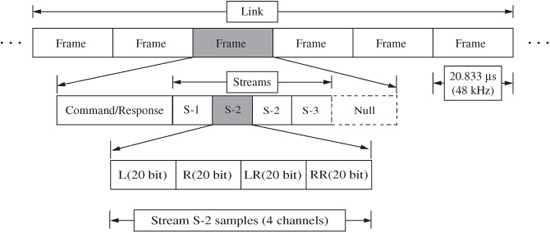
FIGURE 14.4 The data frame composition used in the HD Audio specification, defining how streams and channels are transferred on a link.
The link physically connects the controller and the codecs and conveys serial data between them. A time-multiplexed link protocol supports various sampling frequencies and bit resolutions using isochronous (no flow control) transport with a fixed data transfer rate. Generally, all channels in a stream must have the same sampling frequency and bit resolution. Signals on the link are transmitted as a series of data packets called frames. Each next frame occurs at 20.833 μs, corresponding to a 48-kHz sampling frequency, as shown in Fig. 14.4.
Each frame contains command information and as many stream sample blocks as needed. The total number of streams that can be supported is limited by the content of all the streams; unused capacity is filled with null data. Frames occur at a fixed rate of 48 kHz so if a stream has a sampling frequency less than or more than 48 kHz, there is less than or more than one sample block in each frame (multiple blocks are transmitted at one time in the packet). For example (see Fig. 14.4), some frames contain two sample blocks (S2) and some frames contain none. A single stream sample block can contain one sample for each of the multiple channels in the stream. For example (see Fig. 14.4), the illustrated S2 stream contains four channels (L, R, LR, and RR) and each channel has 20-bit samples; the stream thus uses 80 bits per sample block. This stream has a 96-kHz sampling frequency since two sample blocks are conveyed per 20.833 μs frame.
Samples are packed in containers that are 8, 16, or 32 bits wide; the smallest container size which will fit the sample is used. For example, 24-bit samples are placed in 32-bit containers; samples are padded with zeros at the LSB to left-justify the sample in the container. A block contains sets of samples to be played at a point in time. A block size equals the container size multiplied by the number of channels; for example, a 24-bit, 3-channel, 96-kHz stream has a block size of 12 bytes. The same stream has a packet size of 24 bytes.
The specification allows considerable flexibility in system design and application. For example, a stereo analog signal might be input through an A/D converter for internal recording at 44.1 kHz and 16 bits; a 7.1-channel signal is output from a DVD disc at 96 kHz and 24 bits; a stereo 22-kHz, 16-bit signal is mixed into the front two channels of the 7.1-channel playback; a connected headset plays a communications stream from a net meeting—all functions occurring simultaneously. Also, the sequential order of processing can be specified; for example, a compressor/limiter can be placed before equalization, which will yield a different result from the reverse order.
Implementations of controllers and codecs are available from numerous companies. HD Audio is supported by a Universal Audio Architecture (UAA) class driver in Microsoft Windows XP SP3 and in Windows Vista; the AppleHDA driver is included in Mac OS X; Linux and other open operating systems support HD Audio. The HD Audio specification is available for download from the Intel Web site.
Windows DirectX API
The DOS programming environment provided simple and low-level access to functions, allowing full implementation of audio and video features. The Windows operating system added considerable complexity. The Windows Multimedia API allowed access to sound-card functionality. However, developers could not access peripherals directly—they were limited to whatever access functions Windows provided. For example, the Multimedia API provides no direct means to mix audio files.
Microsoft’s DirectX API suite was designed overcome these kinds of limitations, and promote high-performance multimedia application development in Windows. DirectX APIs effectively provide real-time, low-level access to peripherals specifically used in intensive audio/video applications. DirectX APIs divide multimedia tasks into components including DirectSound, DirectSound3D, DirectMusic, DirectShow, Direct-Draw, Direct-Play, DirectInput, and DirectSetup.
DirectSound provides device-independent access to audio accelerator hardware. It provides functions for mixing audio files and controlling each file’s volume, balance, and playback rate within the mix. This allows real-time mixing of audio streams as well as control over effects like panning. DirectSound also provides low-latency playback so that sounds can be synchronized with other multimedia events.
The DirectSound3D API is an extension to DirectSound. It is a set of functions that allow application programmers to add 3D audio effects to the audio content, imparting 3D sound over two speakers or headphones. The programmer can establish the 3D coordinates (x, y, z) of both the listener and sound source. It does not assume that the listener’s central axis is in the center of the screen. The DirectSound3D API allows processing to be done natively on the local CPU, or on an expansion card’s hardware DSP chip. In this way, the maximum number of applications can employ 3D audio, with appropriate degrees of processing overhead depending on the resources available.
DirectMusic is an extension to DirectX that provides wavetable synthesis with support for Downloadable Sounds (DLS), interactive music composition, and DLS and other authoring tools. DLS is an extension to the MIDI specification that defines a file format, device architecture, and API. DLS lets synthesizer developers add custom wavetables to the General MIDI sounds already stored in a sound card’s ROM. Using system memory, DLS-compatible devices can automatically download sounds from discs, the Internet, or other sources. DirectMusic also provides a music composition engine that lets developers specify the style and characteristics of a musical accompaniment, and also change these parameters in terms of tempo or voicing.
DirectShow (Version 5.2 and later) supports DVD decoders and DVD applications. It demultiplexes the MPEG-2 bitstream from the disc so that audio, video, sub-picture and other decoding can be performed in real time with dedicated hardware or software means; in either case, the interface is the same. DirectShow supports aspects of DVD playback such as navigation, regional management, and exchange of CSS encrypted data.
Vendors provide DirectX drivers in addition to their standard Windows drivers. For example, a SoundBlaster DirectX driver provides access to fast SRAM on a Sound-Blaster card, accelerating audio functionality. If a vendor does not supply a DirectX driver, DirectX provides an emulated driver. Applications may use this driver when audio acceleration hardware is not available. Although the emulated driver is slower, the developer retains access to the enhanced functionality. DirectX thus gives developers access to low-level hardware functions.
MMX
Companies have developed single-chip solutions to relieve the central processor of audio computation burdens. However, simultaneously, processors have become more adept at performing multimedia calculations. For example, the Intel Multimedia Extensions (MMX) instruction set contained in Pentium processors is expressly designed to accelerate graphics, video, and audio signal processing. Among other attributes, these 57 instructions allow a Pentium processor to simultaneously move and process eight bytes—seven more than previous Pentiums. In particular, this capability is called Single Instruction, Multiple Data (SIMD) and is useful for processing complex and multiple audio streams. MMX instructions also double the onboard L1 memory cache to 32 kbytes and provide other speed advantages. Using Intel’s benchmarks, media software written for MMX will run 40 to 66% faster for some tasks. This efficiency allows faster execution and frees other system resources for still more sophisticated processing. Some Intel MMX processors will play DVD-Video movies and decode their Dolby Digital soundtracks. However, software-based processing on the host CPU has its limitations. If a 500-MHz processor devotes half its power to processing surround sound, wavetable synthesis, and video decoding, it effectively becomes a 250-MHz processor for other simultaneous applications.
File Formats
Interfaces such as AES3 convey digital audio data in real time. In other applications, transfer is not in real time (it can be faster or slower). Defined file formats are needed to transfer essence (content data such as audio) along with metadata (nonaudio data such as edit lists). In this way, for example, one creator or many collaborators can author projects with an efficient workflow. Moreover, essence can be transferred from one platform to another. In still other applications, file formats are specifically designed to allow streaming. In a multimedia environment, audio, video, and other data is intermingled.
Media content data such as audio, video, still pictures, graphics, and text is sometimes known as essence. Other related data can be considered as data describing data, and is called metadata. Metadata can hold parameters (such as sampling frequency, downmixing, and number of channels) that describe how to decode essence, can be used to search for essence, and can contain intellectual property information such as copyright and ownership needed to access essence. Metadata can also describe how to assemble different elements (this metadata is sometimes called a composition), and provides information on synchronization.
In some cases, audio data is stored as a raw data, headerless sound file that contains only amplitude samples. However, in most cases, dedicated file formats are used to provide compatibility between computer platforms so that essence can be stored, then transmitted or otherwise moved to other systems, and be compatibly processed or replayed. In addition to audio (or video) data, many file formats contain an introductory header with metadata such as the file’s sampling frequency, bit resolution, number of channels, and type of compression (if any), title, copyright, and other information. Some file formats also contain other metadata. For example, a file can contain an edit decision list with timecode and crossfade information, as well as equalization data. Macintosh files use a two-part structure with a data fork and resource fork; audio can be stored in either mode. Many software programs can read raw or coded files and convert them into other formats. Some popular file formats include WAV, AIFF, SDII, QuickTime, JPEG, MPEG, and OMFI.
WAV and BWF
The Waveform Audio (WAV) file format (.wav extension) was introduced in Windows 3.1 as the format for multimedia sound. The WAV file interchange format is described in the Microsoft/IBM Multimedia Programming Interface and Data Specifications document. The WAV format is the most common type of file adhering to the Resource Interchange File Format (RIFF) specification; it is sometimes called RIFF WAV. WAV is widely used for uncompressed 8-, 12-, and 16-bit audio files, both monaural and multi-channel, at a variety of sampling frequencies. RIFF files organize blocks of data into sections called chunks. The RIFF chunk at the beginning of a file identifies the file as a WAV file and describes its length. The Format chunk describes sampling frequency, word length, and other parameters. Applications might use information contained in chunks, or ignore it entirely. The Data chunk contains the amplitude sample values. PCM or non-PCM audio formats can be stored in a WAV file. For example, a format specific field can hold parameters used to specify a data-compressed file such as Dolby Digital or MPEG data. The format chunk is extended to include the additional content, and a “cbSize” descriptor is included along with data describing the extended format. Eight-bit bytes are represented in unsigned integer format and 16-bit bytes are represented in signed two’s complement format.
Figure 14.5 shows one cycle of a monaural 1-kHz square wave recorded at 44.1 kHz and 16 bits and stored as a WAV file. The left-hand field represents the file in hexadecimal form and the right-hand side in ASCII form. The first 12 bytes (each pair of hex numbers is a byte) (52 49 46 46) represent the ASCII characters for RIFF, the file type. The next four bytes (CE 00 00 00) represent the number of bytes of data in the remainder of the file (excluding the first eight header bytes). This field is expressed in “little-endian” form (the term taken from Gulliver’s Travels and the question of which end of a soft-boiled egg should be cracked first). In this case, the least significant bytes are listed first. (Big-endian represents most significant bytes first.) The last four bytes of this chunk (57 41 56 45) identify this RIFF file as a WAV file. The next 24 bytes is the Format chunk holding information describing the file. For example, 44 AC 00 00 identifies the sampling frequency as 44,100 Hz. The Data chunk (following the ASCII word “data”) describes the chunk length, and contains the square-wave data itself, stored in little-endian format. This file concludes with an Info chunk with various text information.
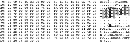
FIGURE 14.5 One cycle of a 1-kHz square wave recorded at 44.1 kHz and saved as a WAV file. The hexadecimal (left-hand field) and ASCII (right-hand field) representations are shown.
The Broadcast Wave Format (BWF) audio file format is an open-source format based on the WAV format. It was developed by the European Broadcasting Union (EBU) and is described in the EBU Tech. 3285 document. BWF files may be considered as WAV files with additional restrictions and additions. BWF uses an additional “broadcast audio extension” header chunk to define the audio data’s format, and contains information on the sound sequence, originator/producer, creation date, a timecode reference, and other data, as shown in Table. 14.1. Each file is time-stamped using a 64-bit value. Thus, one advantage of BWF over WAV is that BWF files can be time-stamped with sample accuracy. Applications can read the time stamp and places files in a specific order or at a specific location, without a need for an edit decision list. The BWF specification calls for a 48-kHz sampling frequency and at least a 16-bit PCM word length. Multichannel MPEG-2 data is supported. It defines parameters such as surround format, downmix coefficients, and channel ordering; multichannel data is written as multiple monaural channels, and not interleaved. BWF files use the same .wav extension as WAV files, and BWF files can be played by any system capable of playing a WAV file (they ignore the additional chunks). However, a BWF file can contain either PCM or MPEG-2 data. Some players will not play MPEG files with a .wav extension. The AES46 standard describes a radio traffic audio delivery extension to the BWF file format. It defines a CART chunk that describes cartridge labels for automated playback systems; information such as timing, cuing, and level reference can be placed in the label.
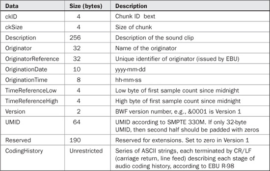
TABLE 14.1 BWF extension chunk format.
MP3, AIFF, QuickTime, and Other File Formats
As noted, MPEG audio data can be placed in AIFF-C, WAV, and BWF file formats using appropriate headers. However, in many cases, MP3 files are used in raw form with the .mp3 extension. In this case, data is represented as a sequence of MPEG audio frames; each frame is preceded by a 32-bit header starting with a unique synchronization pattern of eleven “1s.” These files can be deciphered and playback can initiate from any point in the file by locating the start of the next frame.
The ID3 tag is present in many MP3 files; it can include data such as title, artist, and genre information. This tag is usually located in the last 128 bits of the file. Since it does not begin with an audio-frame synchronization pattern, audio decoders do not play this nonaudio data. An example of an ID3 tag data is shown in Table. 14.2. The ID3v2.2 tag is a more complex tag structure.
The AU (.au) file format was developed for the Unix platform, but is also used on other systems. It supports a variety of linear audio types as well as compressed files with ADPCM or μ law.
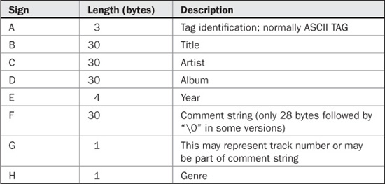
TABLE 14.2 Example of data found in an ID3 tag structure.
The Voice VOC (.voc) file format is used in some sound cards. VOC defines eight block types that can vary in length; sampling frequency and word length are specified. Sound quality up to 16-bit stereo is supported, along with compressed formats. VOC files can contain markers for looping, synchronization markers for multimedia applications, and silence markers.
The AIFF (.aiff or .aif) Audio Interchange File Format is native to Macintosh computers, and is also used in PC and other computer types. AIFF is based on the EA IFF 85 standard. AIFF supports many types of uncompressed data with a variety of channels, sampling frequencies, and word lengths. The format contains information on the number of interleaved channels, sample size, and sampling frequency, as well as the raw audio data. As in WAV files, AIFF files store data in chunks. The FORM chunk identifies the file format, COMM contains the format parameter information, and SSND contains audio data. A big-endian format is used. Markers can be placed anywhere in a file, for example, to mark edit points. However, markers can be used for any purpose, as defined by the application software.
The AIFF format is used for some Macintosh sound files and is recognized by numerous software editing systems. Because sound files are stored together with other parameters, it is difficult to add data, for example, as in a multitrack overdub, without writing a new file. The AIFF-C (compressed) (or AIFC) file format is an AIFF version that allows for compressed audio data. Several types of compression are used in Macintosh applications including Macintosh Audio Compression/Expansion (MACE), IMA/ADPCM, and μ law. AIFF is defined in the context of the EA IFF 85 standard.
The Sound Designer II (SDII or SD2) file format (.sd2) was developed by Digi-Design. It is the successor to the Sound Designer I file format, originally developed for their Macintosh-based recording and editing systems. Audio data is stored separately from file parameters. SDII stores monaural or stereo data. For the latter, tracks are interleaved as left/right samples; samples are stored as signed values. In some applications, left and right channels are stored in separate files; .L and .R suffixes are used. The format contains information on the file’s sampling frequency, word length and data sizes. Parameters are stored in three STR fields. SDII is used to store and transfer files used in editing applications, and to move data between Macintosh and PC platforms.
QuickTime is a file format (.mov) and multimedia extension to the Macintosh operating system. It is cross-platform and can be used to play videos on most computers. More generally, time-based files, including audio, animation, and MIDI can be stored, synchronized and controlled, and replayed. Because of the timebase inherent in a video program, the video itself can be used to control preset actions. QuickTime movies can have multiple audio tracks. For example, different language soundtracks can accompany a video. In addition, audio-only QuickTime movies may be authored. Videos can be played at 15 fps or 30 fps. However, frame rate, along with picture size and resolution, may be limited by hard-disk data transfer rates. QuickTime itself does not define a video compression method; for example, a Sorenson Video codec might be used. Audio codecs can include those in MPEG-1, MPEG-2 AAC, or Apple Lossless Encoder. Using the QuickTime file format, MPEG-4 audio and video codecs can be combined with other QuickTime-compatible technologies such as Macromedia Flash. Applications that use the Export component of QuickTime can create MPEG-4 compatible files. Any .mp4 file containing compliant MPEG-4 video and AAC audio should be compatible with QuickTime.
Hardware and software tools allow users to record video clips to a hard disk, trim extraneous material, compress video, edit video, add audio tracks, then play the result as a QuickTime movie. In some cases, the software can be used as an off-line video editor, and used to create an edit decision list with timecode, or the finished product can be output directly. Audio files with 16-bit, 44.1-kHz quality can be inserted in QuickTime movies. QuickTime also accepts MIDI data for playback. QuickTime can also be used to stream media files or live events in real time. QuickTime also supports iTunes and other applications. The 3GPP and 3GPP2 standards are used to create, deliver, and play back bandwidth-intensive multimedia over 3G wireless mobile cellular networks such as GSM. The standards are based on the QuickTime file format and contain MPEG-4 and H.263 video, AAC and AMR audio, and 3G text; 3GPP2 can also use QCELP audio. QuickTime software, or other software that uses QuickTime exporters, can be used to create and play back 3GPP and 3GPP2 content.
As noted, QuickTime is also available for Windows so that presentations developed on a Macintosh can be played on a PC. The Audio Video Interleaved (AVI) format is similar to QuickTime, but is only used on Windows computers.
The RealAudio (.ra or .ram) file format is designed to play music in real time over the Internet. It was introduced by RealNetworks in 1995 (then known as Progressive-Networks). Both 8- and 16-bit audio is supported at a variety of bit rates; the compression algorithm is optimized for different modem speeds. RA files can be created from WAV, AU, or other files or generated in real time. Streaming technology is described in Chap. 15.
The JPEG (Joint Photographic Experts Group) lossy video compression format is used primarily to reduce the size of still image files. Compression ratios of 20:1 to 30:1 can be achieved with little loss of quality, and much higher ratios are possible. Motion JPEG (MJPEG) can be used to store a series of data-reduced frames comprising motion video. This is often used in video editors where individual frame quality is needed. Many proprietary JPEG formats are in use. The MPEG (Moving Picture Experts Group) lossy video compression methods are used primarily for motion video with accompanying audio. Some frames are stored with great resolution, then intervening frames are stored as differences between frames; video compression ratios of 200:1 are possible. MPEG also defines a number of compressed audio formats such as MP3, MPEG AAC, and others; MPEG audio is discussed in more detail in Chap. 11. MPEG video is discussed in Chap. 16.
Open Media Framework Interchange (OMFI)
In a perfect world, audio and video projects produced on workstations from different manufacturers could be interchanged between platforms with complete compatibility. That kind of common cross-platform interchange language was the goal of the Open Media Framework Interchange (OMFI). OMFI is a set of file format standards for audio, text, still graphics, images, animation, and video files. In addition, it defines editing, mixing, and processing notation so that both content and description of edited audio and video programs can be interchanged. The format also contains information identifying the sources of the media as well as sampling and timecode information, and accommodates both compressed and uncompressed files. Files can be created in one format, interchanged to another platform for editing and signal processing, and then returned to the original format without loss of information. In other words, an OMFI file contains all the information needed to create, edit, and play digital media presentations. In most cases, files in a native format are converted to the OMFI format, interchanged via direct transmission or removable physical media, and then converted to the new native format. However, to help streamline operation, OMFI is structured to facilitate playback directly from an interchanged file when the playback platform has similar characteristics as the source platform. To operate efficiently with large files, OMFI is able to identify and extract specific objects of information such as media source information, without reading the entire file. In addition, a file can be incrementally changed without requiring a complete recalculation and rewriting of the entire file.
OMFI uses two basic types of information. “Compositions” are descriptions of all the data required to play or edit a presentation. Compositions do not contain media data, but point to them and provide coordinated operation using methods such as time-code-based edit decision lists, source/destination labels, and crossfade times. “Physical sources” contain the actual media data such as audio and video, as well as identification of the sources used in the composition. Data structures called media objects (or mobs) are used to identify compositions and sources. An OMFI file contains objects—information that other data can reference. For example, a composition mob is an object that contains information describing the composition; an object’s data is called its values. An applications programming interface (API) is used to access object values and translate proprietary file formats into OMFI-compatible files.
OMFI allows file transfer such as via disc or transmission on a network. Common file formats included in the OMFI format are TIFF (including RGB, JPEG, and YCC) for video and graphics, and AIFC and WAV for audio. Clearly, a common transmission method must be used to link stations; for example, Ethernet, FDDI, ATM, or TCP/IP could be used. OMFI can also be used in a client-server system that allows multi-user real-time access from the server to the client.
OMFI was migrated to Microsoft’s Structured Storage container format to form the core of the Advanced Authoring Format (AAF). AAF also employs Microsoft’s Component Object Model (COM), an inter-application communication protocol supported by most popular programming languages including C++ and Java. The Bento format, developed by Apple, links elements of a project within an overall container; it is used with OMFI. Both OMFI Version 1 and OMFI Version 2 are used. They differ to the extent that they can be incompatible. OMFI was developed by Avid Corporation.
Advanced Authoring Format (AAF)
The Advanced Authoring Format (AAF) is a successor to the OMFI specification. Introduced in 1998, AAF is an open-source interchange protocol for professional multimedia post-production and authoring applications (not delivery). Essence and metadata can be exchanged between multiple users and facilities, diverse platforms, systems, and applications. It defines the relationship between content elements, maps elements to a timeline, synchronizes content streams, describes processing, tracks the history of the file, and can reference external essence not in the file. For example, it can convey complex project structures of audio, video, graphics, and animation that enable sample-accurate editing from multiple sources, along with the compositional information needed to render the materials into finished content. For example, an AAF file might contain 60 minutes of video, 100 still images, 20 minutes of audio, and references to external content, along with instructions to process this essence in a certain way and combine them into a 5-minute presentation. AAF also uses variable key length encoding; chunks can be appended to a file and be read only by those with the proper key. Those without the key skip the chunk and read the rest of the file. In this way, different manufacturers can tailor the file for specific needs while still adhering to the format, and new metadata can be added to the standard as well.

FIGURE 14.6 An example of how audio post-production metadata might appear in an AAF file.
Considerable flexibility is possible. For example, a composition package has slots that may be considered as independent tracks, as shown in Fig. 14.6. Each slot can describe one kind of essence. Slots can be time-independent, can use a timecode reference, or be event-based. Within a slot, a segment might hold a source clip. That clip might refer to a section of another slot in another essence package, which in turn refers to an external sound file.
AAF uses a Structured Storage format implemented in a C++ environment. As an AAF file is edited, its version control feature can keep a record of the revisions. The AAF Association was founded by Avid and Microsoft.
Material eXchange Format (MXF)
The Material eXchange Format (MXF) is a media format for the exchange of program material. It is used in professional post-production and authoring applications. It provides a simplified standard container format for essence and metadata, and is platform-independent. It is closely related to AAF. Files comprise a sequence of frames where each frame holds audio, video, and data content along with frame-based metadata. MXF files can contain any particular media format such as MEG, WAV, AVI, or DPX; and MPX files may be associated with AAF projects. MXF and AAF use the same internal data structure, and both use the SMPTE Metadata Dictionary to define data and workflow information. However, MXF promotes a simpler metadata that is compatible with AAF. MXF files can be read by an AAF workstation, for example, and be integrated into a project. An AAF file might comprise only metadata, and simply reference the essence in MXF files.
MXF’s data structure offers a partial retrieve feature so that users can retrieve only sections of a file that are pertinent to them without copying the entire file. Because essence is placed in a temporal streaming format, data can be delivered in real time, or conveyed with conventional file-transfer operations. Because data is sequentially arranged, MXF is often used for finished projects and for writing to media. MXF was developed by the Pro-MPEG Forum, EBU, and SMPTE.
AES31
The AES31 specification is a group of non-proprietary specifications used to interchange audio data and project information between devices such as workstations and recorders. It allows simple exchange of one audio file or exchanges of complex files with editing information from different devices. There are four independent stages with interchange options. AES31-1 defines the physical data transport describing how files can be moved via removable media or high-speed network. It is compatible with the Microsoft FAT32 disk filing structure. AES31-2 defines an audio file format, describing how BWF data chunks should be placed on a storage media or packaged for network transfer. AES31-3 defines a simple project structure using a sample-accurate audio decision list (ADL) that can contain information such as levels and anti-click and creative crossfades, and allows files to be played back in synchronization; files use the .adl extension. It uses a URL to identify a file source, whether residing locally or on a network. It also provides interchange between NTSC and PAL formats. For user convenience, edit lists are conveyed with human-readable ASCII characters; the Edit Decision Markup Language (EDML) is used. AES31-4 defines an object-oriented project structure capable of describing a variety of characteristics. In AES31, a universal resource locator can access files on different media or platforms; the locater specifies the file, host, disk volume, directory, subdirectories, and the file name with a .wav extension.
Digital Audio Extraction
In digital audio extraction (DAE), music data is copied from a CD with direct digital means, without conversion to an analog signal, using a CD- or DVD-ROM drive to create a file (such as a WAV file) on the host computer. The copy is ostensibly an exact bit-for-bit copy of the original data—a clone. Performing DAE is not as easy as copying a file from a ROM disc. Red Book data is stored as tracks, whereas Yellow Book and DVD data is stored as files. CD-ROM (and other computer data) is formatted in sectors with unique addresses that inherently provide incremental reading and copying. Red Book does not provide this. Its track format supposes that the data spiral will be mainly read continuously, as when normally listening to music, thus there is no addressing provision. With DAE, the system reads this spiral discontinuously, and must piece together a continuous file. Moreover, when writing a CD-R or CD-RW disc, the data sent to the recorder must be absolutely continuous. If there is an interruption at the writing laser, the recording is unusable. One application of DAE is the illegal copying of music. DAE is often known as “ripping,” which also generally refers to the copying of music into files.
CD-ROM (and DVD-ROM) drives are capable of digitally transferring information from a CD-ROM disc to a host computer. The transfer is made via an adapter or interface connected to the drive. CD-ROM drives can also play back CD-Audio discs by reading the data through audio converters and analog output circuits, as in regular CD-Audio players. Users may listen to the audio CD through the computer sound system or a CD-ROM headphone jack. With DAE software, a CD-ROM drive may also deliver this digital audio data to a computer. In this case, the computer requests audio data from the CD-ROM drive as it would request computer data. Because of the differences between the CD-ROM and CD-Audio file formats, DAE requires special logic, either in hardware, firmware (a programmable chip in the data path) or a software program on the host. This logic is needed to correct synchronization errors that would result when a CD-Audio disc is read like a CD-ROM disc.
As described in Chap. 7, CD-Audio data is organized in frames, each with 24 bytes of audio information. There is no unique identifier (address) for individual frames. Each frame also contains eight subcode bits. These are collected over 98 frames to form eight channels, each 98 bits in length. Although Red Book CD players do not do this, computers can collect audio bytes over 98 frames, yielding a block of 2352 audio bytes. In real playing time, this 98-frame block comprises 1/75th of a second. In computer parlance, this block is sometimes called a sector or raw sector. For CD-Audio, there is no distinction between a sector and a raw sector because all 2352 bytes of data are “actual” audio data. The subcode contains the time in minutes:seconds:frames (called MSF time) of the subcode block. This MSF time is displayed by CD-Audio players as track time.
In the CD-Audio player, audio data and subcode are separated and follow different processing paths. When a computer requests and receives audio data, it is not accompanied by any time or address data. Moreover, if the computer were to separately request subcode data, it would not be known which group of 98 frames the time/address refers to, and in any case the time/address cannot be placed in the 2352-byte sector, which is occupied by audio data. In contrast, CD-ROM data is organized in blocks, each with 2352 bytes; 2048 of these bytes contain the user data (CD-ROM Mode 1). The remaining bytes are used for error correction and to uniquely identify that block of data with an address; this is called a sector number. A 2352-byte block is called a raw sector. The 2048 bytes of data in the raw sector are called a sector. Importantly, the block’s data and its address are intrinsically combined. When a computer requests and receives a block of CD-ROM data, both the data and its disc address are present and can be placed in a 2352-byte sector. In this way, the computer can identify the contents and position of data read from a CD-ROM disc.
In the CD-ROM format the unique identifier or address is carried as part of the block itself. The CD-ROM drive must be able to locate specific blocks of data because of the way operating systems implement their File I/O Services. (File I/O Services are also used to store data on hard disks.) As files are written and deleted, the disk becomes fragmented. The File I/O Services may distribute one large file across the disc to fill in these gaps. The file format used in CD-ROM discs was designed to mimic the way hard-disk drives store data—in sectors. The storage medium must therefore provide a way to randomly access any sector. By including a unique address in each block, CD-ROM drives can provide this random access capability.
CD-Audio discs do not need addresses because the format was designed to deliver continuous streams of music data. A 4-minute song comprises about 42 million bytes of data. Attaching unique addresses to every 24-byte frame would needlessly waste space. On the other hand, some type of random access is required, so the user can skip to a different song or fast-forward through a song. However, these accesses do not need to be completely precise. This is where the MSF subcode time is used. A CD-Audio player finds a song, or a given time on the disc, by reading the subcode and placing the laser pickup close to the accompanying block that contains the target MSF in its subcode. However, because each MSF time is only accurate to 1/75th of a second, the resolution is only 98 frames. A CD-Audio player can only locate data within a block 1/75th of a second prior to the target MSF time.
Because CD-ROM drives evolved from CD-Audio players, they incur the same problem. If asked to read a certain sector on a CD-ROM disc, they can only place the pickup just before the target sector, not right on it. However, since the CD-ROM blocks are addressable (uniquely identifiable) the CD-ROM drive can read through the partial sector where it starts, and wait until the correct sector appears. When the correct sector starts, it will begin streaming data into its buffer. This method is reliable because each CD-ROM block is intrinsically addressed; the address of each data block is known when the block is received.
CD-ROM drives can also mimic sector reading from a CD-Audio disc. CD-ROM drives respond to two types of read commands: Read Sector and Read Raw Sector. Read Sector commands will transfer only the 2048 actual data bytes from each raw sector read. In normal CD-ROM operations, the Read Sector command is typically used. If needed, an application may issue a Read Raw Sector command, which will transfer all 2352 bytes from each raw sector read. The application might be concerned with the CD-ROM addresses or error correction.
By reading 98 CD-Audio frames to form a 2352-byte block, the computer can issue a Read Raw Sector command to a CD-Audio disc in a CD-ROM drive. This works, but not perfectly. The flow, as documented by Will Pirkle, works like this:
1. The host program sends a Read Raw Sector command to read a sector (e.g., #1234) of an audio disc in a CD-ROM drive.
2. The CD-ROM drive converts the sector number into an approximate MSF time.
3. The CD-ROM searches the subcode until it locates the target MSF, and it moves the pickup to within 1/75th of a second before the correct accompanying block (sector) and somewhere inside the previous block (sector #1233).
4. The CD-ROM begins reading data. It loads the data into its buffer for output to the host computer. It does not know the address of each received block, so it cannot locate the next sector properly. The CD-ROM drive reads out exactly 2352 bytes and then stops, somewhere inside sector #1234.
In this example, the program read one block’s worth of data (2352 bytes); however, it did not get the correct (or one complete) block. It read part of the previous block and part of the correct block. This is the crux of the DAE problem.
In DAE, large data files are moved from the ROM drive to either a CD/DVD recorder or a hard disk. Large-scale data movement cannot happen continuously in the PC environment. The flow of data is intermittent and intermediate buffers (memory storage locations) are filled and emptied to simulate continuous transfer. Thus, the ROM drive will read sectors in short bursts, with gaps of time between the data transfers. This exacerbates the central DAE problem because the ROM drive must start and stop its reading mechanism millions of times during the transfer of one 4-minute song. The DAE software must sort the partial blocks, which will occur at the beginning and end of each burst of data, and piece the data together, not repeating redundant data, or skipping data. Any device performing DAE, be it the ROM drive, the adapter, the driver, or host software, faces the same problem of dealing with the overlapping of incorrect data.
The erroneous data read from the beginning and end of the data buffers is a result of synchronization error. If left uncorrected, these synchronization errors manifest themselves as periodic clicks, pops, or noise bursts in the extracted music. Clearly, DAE errors must be corrected by matching known good data to questionable data. This matching procedure is essential in any DAE system. ROM drives may also utilize high-accuracy motors to try to place the laser pickup as close as possible to a target CD-Audio sector. Even highly accurate motors cannot guarantee perfect sector reads. Some type of overlap and compare method must be employed.
This overlap technique has no other function except to perform DAE. A ROM drive, adapter, or host software that implements DAE must apply several engineering methods to properly correct the synchronization errors that occur when a CD-Audio disc is accessed like a CD-ROM disc. Only then may these accesses transfer correct digital audio data from a given CD-Audio source. The ATAPI specification defines drive interfacing. The command set in newer revisions of the specification provides better head-positioning and supports error-correction and subcode functions and thus simplifies software requirements and expedites extraction.
Flash Memory
Portable flash memory offers a small and robust way to store data to nonvolatile solid-state memory (an electrically erasable programmable read-only memory or EEPROM), via an onboard controller. A variety of flash memory formats have been developed, each with a different form factor. These formats include the Compact Flash, Memory Stick, SD, and others. Flash memories on cards are designed to directly plug into a receiving socket. Other flash memory devices interface via a USB or other means. Flash memory technology allows high storage capacity of many gigabytes using semiconductor traces of 130-nm thickness, or as thin as 80 nm. Data transfer rates of 20 Mbps and higher are available. Some cards also incorporate WiFi or Bluetooth for wireless data exchange and communications. Flash memory operates with low power consumption and does not generate heat.
The Compact Flash format uses Type I and Type II form factors. Type II is larger than Type I and requires a wider slot; Type I cards can use Type II slots. The SD format contains a unique, encrypted key, using the Content Protection for Recordable Media (CPRM) standard. The SDIO (SD Input/Output) specification uses the standard SD socket to also allow portable devices to connect to peripherals and accessories. The MultiMediaCard format is a similar precursor to SD, and can be read in many SD devices. Memory Stick media is available in unencrypted Standard and encrypted MagicGate forms. Memory Stick PRO provides encryption and data loss protection features. Specifications for some flash memory formats are given in Table. 14.3.
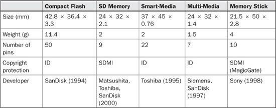
TABLE 14.3 Specifications for removable flash memory formats.
Hard-Disk Drives
Both personal computers and dedicated audio workstations are widely used for audio production. From a hardware standpoint, the key to both systems is the ability to store audio data on magnetic hard-disk drives. Hard-disk drives offer fast and random access, fast data transfer, high storage capacity, and low cost. A hard-disk-based audio system consolidates storage and editing features and allows an efficient approach to production needs. Optical disc storage has many advantages, particularly for static data storage. But magnetic hard-disk drives are superior for the dynamic workflow of audio production.
Magnetic Recording
Magnetic media is composed of a substrate coated with a thin layer of magnetic material, such as gamma ferric oxide (Fe2O3). This material is composed of particles that are acicular (cigar-shaped). Each particle exhibits a permanent magnetic pole structure that produces a constant magnetic field. The orientation of the magnetic field can be switched back and forth. When a media is unrecorded, the magnetic fields of the particles have no net orientation. To record information, an external magnetic field orients the particles’ magnetic fields according to the alignment of the applied field. The coercivity of the particles describes the strength of the external field that is needed to affect their orientation. Further, the coercivity of the particles exhibits a Gaussian distribution in which a few particles are oriented by a weak applied field, and the number increases as the field is increased, until the media saturates and an increase in the external field will no longer change net magnetization.
Saturation magnetic recording is used when storing binary data. The force of the external field is increased so that the magnetic fields in virtually all the particles are oriented. When a bipolar waveform is applied, a saturated media thus has two states of equal magnitude but opposite polarity. The write signal is a current that changes polarity at the transitions in the channel bitstream. Signals from the write head cause entire regions of particles to be oriented either positively or negatively. These transitions in magnetic polarity can represent transitions between 0 or 1 binary values. During playback, the magnetic medium with its different pole-oriented regions passes before a read head, which detects the changes in orientation. Each transition in recorded polarity causes the flux field in the read head to reverse, generating an output signal that reconstructs the write waveform. The strength of the net magnetic changes recorded on the medium determines the medium’s robustness. A strongly recorded signal is desired because it can be read with less chance of error. Saturation recording ensures the greatest possible net variation in orientation of domains; hence, it is robust.
Hard-Disk Design
Hard-disk drives offer reliable storage, fast access time, fast data transfer, large storage capacity, and random access. Many gigabytes of data can be stored in a sealed environment at an extremely low cost and in a relatively small size.
In most systems, the hard disk media is nonremovable; this lowers manufacturing cost, simplifies the medium’s design, and allows increased capacity. The media usually comprises a series of disks, usually made of rigid aluminum alloy, stacked on a common spindle. The disks are coated on the top and bottom with a magnetic material such as ferric oxide, with an aluminum-oxide undercoat. Alternatively, metallic disks can be electroplated with a magnetic recording layer. These magnetic thin-film disks allow closer spacing of data tracks, providing greater data density and faster track access. Thin-film disks are more durable than conventional oxide disks because the data surface is harder; this helps them to resist head crashes. Construction of a hard-disk drive is shown in Fig. 14.7.
Hard disks rotate whenever the unit is powered. This is because the mass of the system might require several seconds to reach proper rotational speed. A series of read/write heads, one for each magnetic surface, are mounted on an arm called a head actuator. The actuator moves the heads across the disk surfaces in unison to seek data. In most designs, only one head is used at a time (some drives used for digital video are an exception); thus, read/write circuitry can be shared among all the heads. Hard-disk heads float over the magnetic surfaces on a thin cushion of air, typically 20 μm or less. The head must be aerodynamically designed to provide proper flying height, yet negotiate disk surface warping that could cause azimuth errors, and also fly above disk contaminants. However, the flying height limits data density due to spacing loss. A special, lubricated portion of the disc is used as a parking strip. In the event of a head crash, the head touches the surface, causing it to burn (literally, crash and burn). This usually catastrophically damages both the head and disks, necessitating, at best, a data-recovery procedure and drive replacement.
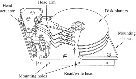
FIGURE 14.7 Construction of a hard-disk drive showing disk platters, head actuator, head arm, and read/write heads. (Mueller, 1999)
Some disk drives use ferrite heads with metal-in-gap and double metal-in-gap technology. The former uses metal sputtered in the trailing edge of the recording gap to provide a well-defined record pulse and higher density; the latter adds additional magnetic material to further improve head response. Some heads use thin-film technology to achieve very small gap areas, which allows higher track density. Some drives use magneto-resistive heads (MRH) that use a nano-sized magnetic material in the read gap with a resistance that varies with magnetic flux. Typically, only one head is used at a time. The same head is used for both reading and writing; precompensation equalization is used during writing. Erasing is performed by overwriting. Several types of head actuator designs are used; for example, a moving coil assembly can be used. The moving coil acts against a spring to position the head actuator on the disk surface. Alternatively, an electric motor and carriage arrangement could be used in the actuator. Small PCMCIA drives use a head-to-media contact recording architecture, thin-film heads, and vertical recording for high data density.
To maintain correct head-to-track tolerances, some drives calibrate their mechanical systems according to changes in temperature. With automatic thermal recalibration, the drive interrupts data flow to perform this function; this is not a hardship with most data applications, but can interrupt an audio or video signal. Some drives use smart controllers that do not perform thermal recalibration when in use; these drives (sometimes called AV drives) are recommended for critical audio and video applications.
Data on the disk surface is configured in concentric data tracks. Each track comprises one disk circumference for a given head position. The total tracks provided by all the heads at a given radius position is known as a cylinder—a strictly imaginary construction. Most drives segment data tracks into arcs known as sectors. A particular physical address within a sector, known as a block, is identified by a cylinder (positioner address), head (surface address), and sector (rotational angle address). Modified frequency modulation (MFM) coding as well as other forms of coding such as 2/3 and 2/7 run-length limited codes are used for high storage density.
Hard-disk drives were developed for computer applications where any error is considered fatal. Drives are assembled in clean rooms. The atmosphere inside the drive housing is evacuated, and the unit is hermetically sealed to protect the media from contamination. Media errors are greatly reduced by the sealed disk environment. However, an error correction encoding scheme is still needed in most applications. Manufactured disk defects, resulting in bad data blocks, are logged at the factory, and their locations are mapped in directory firmware so the drive controller will never write data to those defective addresses. Some hard-disk drives use heat sinks to prevent thermal buildup from the internal motors. In some cases, the enclosure is charged with helium to facilitate heat dissipation and reduce disk drag.
Data can be output in either serial or parallel; the latter provides faster data transfer rates. For faster access times, disk-based systems can be designed to write data in a logically organized fashion. A method known as spiraling can be used to minimize interruptions in data transfer by reducing sector seek times at a track boundary. Overall, hard disks should provide a sustained transfer rate of 5 to 20 Mbyte/s and access time (accounting for seek time, rotational latency, and command overhead) of 5 ms. Some disk drives specify burst data transfer rates; a sustained rate is a more useful specification. A rotational speed of 7,200 rpm to 15,000 rpm is recommended for most audio applications. In any case, RAM buffers are used to provide a continuous flow of output data.
Hard-disk drives are connected to the host computer via SCSI, IDE (ATA), Firewire, USB, EIDE (ATA-2), and Ultra ATA (ATA-3 or Ultra DMA) connections. ATA drives offer satisfactory performance at a low price. SCSI-2 and SCSI-3 drives offer faster and more robust performance compared to EIDE; up to 15 drives can be placed on a wide SCSI bus. In practice, the transfer rate of a hard disk is faster than that required for a digital audio channel. During playback, the drive delivers bursts of data to the output buffer which in turn steadily delivers output data. The drive is free to access data randomly distributed on different platters. Similarly, given sufficient drive transfer rate, it is possible to record and play back multiple channels of audio. High-performance systems use a Redundant Array of Independent Disks (RAID) controller; RAID level 0 is often used in audio or video applications. A level 0 configuration uses disk mirroring, writing blocks of each file to multiple drives, to achieve fast throughput.
It is sometimes helpful to periodically defragment or optimize a drive; a bundled or separate utility program places data into continuous sections for faster access. Most disk editing is done through an edit decision list in which in/out and other edit points are saved as data addresses. Music plays from one address, and as the edit point approaches, the system accesses the next music address from another disk location, joining them in real time through a crossfade. This allows nondestructive editing; the original data files are not altered. Original data can be backed up to another medium, or a finished recording can be output using the edit list.
Highly miniaturized hard-disk drives are packaged to form removable cards that can be connected via USB or plugged directly into a receiving slot. This drive technology is sometimes known as “IBM Microdrive.” The magnetic platter is nominally “1 inch” in diameter; the card package measures 42.8 × 36.4 × 5 mm overall. Other devices use platters with 17-mm or 18-mm diameter; outer card dimensions are 36.4 × 21.4 × 5 mm. Both flash memory and Microdrive storage are used for portable audio and video applications. Microdrives offer low cost per megabyte stored.
Digital Audio Workstations
Digital audio workstations are computer-based systems that provide extensive audio recording, storage, editing, and interfacing capabilities. Workstations can perform many of the functions of a traditional recording studio and are widely used for music production. The low cost of personal computers and audio software applications has encouraged their wide use by professional music engineers, musicians, and home recordists. The increase in productivity as well as creative possibilities, are immense.
Digital audio workstations provide random access storage, and multitrack recording and playback. System functions may include nondestructive editing; digital signal processing for mixing, equalization, compression, and reverberation; subframe synchronization to timecode and other timebase references; data backup; networking; media removability; external machine control; sound-cue assembly; edit decision list I/O; and analog and digital data I/O. In most cases, this is accomplished with a personal computer, and dedicated audio electronics that are interfaced to the computer, or software plug-in programs that add specific functionality. Workstations provide multi-track operation. Time-division multiplexing is used to overcome limitations of a hardwired bus structure. In this way, the number of tracks does not equal the number of audio outputs. In theory, a system could have any number of virtual tracks, flexibly directed to inputs and outputs. In practice, as data is distributed over a disk surface, access time limits the number of channels that can be output from a drive. Additional disk drives can increase the number of virtual tracks available; however, physical input/output connections ultimately impose a constraint. For example, a system might feature 256 virtual tracks with 24 I/O channels.
Digital audio workstations use a graphical interface, with most human action taking place with a mouse and keyboard. Some systems provide a dedicated hardware controller. Although software packages differ, most systems provide standard “tape recorder” transport controls along with the means to name autolocation points, and punch-in and punch-out indicators. Time-scale indicators permit material to be measured in minutes, seconds, bars and beats, SMPTE timecode, or feet and frames. Grabber tools allow regions and tracks to be moved; moves can be precisely aligned and synchronized to events. Zoomer tools allow audio waveforms to be viewed at any resolution, down to the individual sample, for precise editing. Other features include fading, crossfading, gain change, normalization, tempo change, pitch change, time stretch and shrink, and morphing.
Digital audio workstations can provide mixing console emulation including virtual mixing capabilities. An image of a console surface appears on the display, with both audio and MIDI tracks. Audio tracks can be manipulated with faders, pan pots, and equalization modules, and MIDI tracks addressed with volume and pan messages. Other console controls include mute, record, solo, output channel assignment, and automation. Volume Unit (VU) meters indicate signal level and clipping status. Nondestructive bouncing allows tracks to be combined during production, prior to mix down. Digital signal processing can be used to perform editing, mixing, filtering, equalization, reverberation, and other functions. Digital filters may provide a number of filter types, and filters can provide smoothing function between previous and current filter settings.
Although the majority of workstations use off-the-shelf Apple or PC computers, some are dedicated, stand-alone systems. For example, a rack-mount unit can contain multiple hard-disk drives, providing recording capability for perhaps 96 channels. A remote-control unit provides a control surface with faders, keyboard, track ball, and other controllers.
Audio Software Applications
Audio workstation software packages permit audio recording, editing, processing, and analysis. Software packages permit operation in different time modes including number of samples, absolute frames, measures and beats, and different SMPTE timecodes. They can perform audio file conversion, supporting AVI, WAV, AIFF, RealAudio, and other file types. For example, AVI files allow editing of audio tracks in a video program. In most cases, software can create samples and interface with MIDI instruments.
The user can highlight portions of a file, ranging from a single sample to the entire piece, and perform signal processing. For example, reverberation could be added to a dry recording, using presets emulating different acoustical spaces and effects. Time compression and expansion allow manipulation of the timebase. For example, a 70-second piece could be converted to 60 seconds, without changing the pitch. Alternatively, music could be shifted up or down a standard musical interval, yielding a key change. A flat vocal part can be raised in pitch. A late entrance can be moved forward by trimming the preceding rest. A note that is held too long can be trimmed back. A part that is rushed can be slowed down while maintaining its pitch. Moreover, all those tools can be wielded against musical phrases, individual notes, or parts of notes.
In many cases, software provides analysis functions. A spectrum analysis plug-in can analyze the properties of sound files. This software performs a fast Fourier transform (FFT), so a time-based signal can be examined in the frequency domain. A spectrum graph could be displayed either along one frequency axis, or along multiple frequency axes over time, in a “waterfall” display. Alternatively, signals could be plotted as a spectrogram, showing spectral and amplitude variations over time. Advanced users can select the FFT sample size and overlap, and apply different smoothing windows.
Noise reduction plug-in software can analyze and remove noise such as tape hiss, electrical hum, and machinery rumble from sound files by distinguishing the noise from the desired signal. It analyzes a part of the recording where there is noise, but no signal, and then creates a noiseprint by performing an FFT on the noise. Using the noiseprint as a guide, the algorithm can remove noise with minimal impact on the desired signal. For the best results, the user manually adjusts the amount of noise attenuation, attack and release of attenuation, and perhaps changes the frequency envelope of the noiseprint. Plug-ins can also remove clicks and pops from a vinyl recording. Clicks can be removed with an automatic feature that detects and removes all clicks, or individual defects can be removed manually. The algorithm allows a number of approaches. For example, a click could be replaced by a signal surrounding the click, with a signal from the opposite channel, or a pencil tool could be used to draw a replacement waveform. Conversely, other plug-ins add noises to a new recording, to make it sound vintage.
One of the most basic and important functions of a workstation is its use as an audio editor. With random access storage, instantaneous auditioning, level adjustment, marking, and crossfading, nondestructive edit operations are efficiently performed. Many editing errors can be corrected with an “undo” command.
Using an edit cursor, clipboard, cut and paste, and other tools, sample-accurate cutting, copying, pasting, and splicing are easily accomplished. Edit points are located in ways analogous to analog tape recorders; sound is “scrubbed” back and forth until the edit point is found. In some cases, an edit point is assigned by entering a timecode number. Crossfade times can be selected automatically or manually. Edit splices often contain four parameters: duration, mark point, crossfade contour, and level. Duration sets the time of the fade. The mark point identifies the edit position, and can be set to various points within the fade. Crossfade contour sets the gain-versus-time relationship across the edit. Although a linear contour sets the midpoint gain of each segment at −6 dB, other midpoint gains might be more suitable. The level sets the gain of any segments edited together to help match them.
Most editing tasks can be broken down into cut, copy, replace, align, and loop operations. Cut and copy functions are used for most editing tasks. A cut edit moves marked audio to a selected location, and removes it from the previous location. However, cut edits can be broken down into four types. A basic cut combines two different segments. Two editing points are identified, and the segments joined. A cut/insert operation moves a marked segment to a marked destination point. Three edit points are thus required. A delete/cut edit removes a segment marked by two edit points, shortening overall duration. A fourth cut operation, a wipe, is used to edit silence before or after a segment.
A copy edit places an identical duplicate of a marked audio section in another section. It thus leaves the original segment unchanged; the duration of the destination is changed, but not that of the source. A basic copy operation combines two segments. A copy/insert operation copies a marked segment to a destination marked in another segment. Three edit points are required.
A “replace” command exchanges a marked source section with a marked destination section, using four edit points. Three types of replace operations are performed. An exact replace copies the source segment and inserts it in place of the marked destination segment. Both segment durations remain the same. Because the duration of the destination segment is not changed, any three of the four edit points define the operation. The fourth point could be automatically calculated. A relative replace edit operation permits the destination segment to be replaced with a source segment of a different duration; the location of one edit point is simply altered. A replace-with-silence operation writes silence over a segment. Both duration and timecode alignment are unchanged.
An “align” edit command slips sections relative to timecode, slaving them to a reference, or specifying an offset. Several types of align edits are used. A synchronization align edit is used to slave a segment to a reference timecode address. One edit point defines the synchronization reference alignment point in the timecode, and the other marks the segment timecode address to be aligned. A trim alignment is used to slip a segment relative to timecode; care must be taken not to overlap consecutive segments. An offset alignment changes the alignment between an external timecode and an internal timecode when slaving the workstation.
A “loop” command creates the equivalent of a tape loop in which a segment is seamlessly repeated. In effect, the segment is sequentially copied. The loop section is marked with the duration and destination; the destination can be an unused track, or an existing segment.
When any edit is executed, the relevant parameters are stored in an edit list and recalled when that edit is performed. The audio source material is never altered. Edits can be easily revised; moreover, memory is conserved. For example, when a sound is copied, there is no need to rewrite the data. An extensive editing session would result in a short database of edit decisions and their parameters, as well as system configuration, assembled into an edit list. Note that in the above descriptions of editing operations, the various moves and copies are virtual, not physical.
Professional Applications
Much professional work is done on PC-based workstations, as well as dedicated workstations. A range of production and post-production applications are accommodated: music scoring, recording, video sweetening, sound design, sound effects, edit-to-picture, Foley, ADR (automatic dialogue replacement), and mixing. To achieve this, a workstation can combine elements of a multitrack recorder, sequencer, drum machine, synthesizer, sampler, digital effects processor, and mixing board, with MIDI, SMPTE, and clock interfaces to audio and video equipment. Some workstations specialize in more specific areas of application.
Soundtrack production for film and video benefits from the inherent nature of synchronization and random access in a workstation. Instantaneous lockup and the ability to lock to vari-speed timecode facilitates production, as does the ability to slide individual tracks or cues back and forth, and the ability to insert or delete musical passages while maintaining lock. Similarly, a workstation can fit sound effects to a picture in slow motion while preserving synchronization.
In general, to achieve proper artistic balance, audio post-production work is divided into dialogue editing, music, effects, Foley, atmosphere, and mixing. In many cases, the audio elements in a feature film are largely re-created. A workstation is ideal for this application because of its ability to deal with disparate elements independently, locate, overlay, and manipulate sound quickly, synthesize and process sound, adjust timing and duration of sounds, and nondestructively audition and edit sounds. In addition, there is no loss of audio quality in transferring from one digital medium to another.
In Foley, footsteps and other natural sound effects are created to fit a picture’s requirements. For example, a stage with sand, gravel, concrete, and water can be used to record footstep sounds in synchronization with the picture. With a workstation, the sounds can be recorded to disk or memory, and easily edited and fitted. Alternatively, a library of sounds can be accessed in real time, eliminating the need for a Foley stage. Hundreds of footsteps or other sounds can be sequenced, providing a wide variety of effects. Similarly, film and video requires ambient sound, or atmosphere, such as traffic sounds or cocktail party chatter. With a workstation, library sounds can be sequenced, then overlaid with other sounds and looped to create a complex atmosphere, to be triggered by an edit list, or crossfaded with other atmospheres. Disk recording also expedites dialogue replacement. Master takes can be assembled from multiple passes by setting cue points, and then fitted back to picture at locations logged from the original synchronization master. Room ambience can be taken from location tapes, then looped and overlaid on re-recorded dialogue.
A workstation can be used as a master MIDI controller and sequencer. The user can remap MIDI outputs, modify or remove messages such as aftertouch, and transmit patch changes and volume commands as well as song position pointers. It can be advantageous to transfer MIDI sequences to the workstation because of its superior timing resolution. For example, a delay problem could be solved by sliding tracks in fractions of milliseconds.
Workstations are designed to integrate with SMPTE timecode. SMPTE in- and out-points can be placed in a sequence to create a hit list. Offset information can be assigned flexibly for one or many events. Blank frame spaces can be inserted or deleted to shift events. Track times can be slid independently from times of other tracks, and sounds can be interchanged without otherwise altering the edit list.
Commercial production can be expedited. For example, an announcer can be recorded to memory, assigning each line to its own track. In this way, tags and inserts can be accommodated by shifting individual lines backward or forward; transfers and back-timing are eliminated. Likewise “doughnuts” can be produced by switching sounds, muting and soloing tracks, changing keys without changing tempos, cutting and pasting, and manipulating tracks with fade-ins and fade-outs. For broadcast, segments can be assigned to different tracks and triggered via timecode. In music production, for example, a vocal fix is easily accomplished by sampling the vocal to memory, bending the pitch, and then flying it back to the master—an easy job when the workstation records timecode while sampling.
Audio for Video Workstations
Some digital audio workstations provide digital video displays for video editing, and for synchronizing audio to picture. Using video capture tools, the movie can be displayed in a small insert window on the same screen as the audio tools; however, a full-screen display on a second monitor is preferable. Users can prepare audio tracks for QuickTime movies, with random access to many takes. Using authoring tools, audio and video materials can be combined into a final presentation. Although the definitions have blurred, it is correct to classify video edit systems as linear, nonlinear, off-line, and on-line.
Nonlinear systems are disk-based, and linear systems are videotape-based. Off-line systems are used to edit audio and video programs, then the generated edit decision list (EDL) can be transferred to a higher-quality on-line video system for final assembly. In many cases, an off-line system is used for editing, and its EDL is transferred to a more sophisticated on-line system for creation of final materials. In other cases, and increasingly, on-line, nonlinear workstations provide all the tools, and production quality, for complete editing and post-production.
Audio for video workstations offer a selection of frame rates and sampling frequencies, as well as pre-roll, post-roll, and other video prerequisites. Some workstations also provide direct control over external videotape recorders. Video signals are recorded using data reduction algorithms to reduce throughput and storage demands. Depending on the compression ratio, requirements can vary from 8 Mbytes/min to over 50 Mbytes/min. In many cases, video data on a hard disk should be defragmented for more optimal reading and writing.
Depending on the application, either the audio or video program can be designated as the master. When a picture is slaved to audio, for example, the movie will respond to audio transport commands such as play, rewind, and fast forward. A picture can be scrubbed with frame accuracy, and audio dropped into place. Alternatively, a user can park the movie at one location while listening to audio at another location. In any case, there is no waiting while audio or videotapes shuttle while assembling the program. Using machine control, the user can audition the audio program while watching the master videotape, then lay back the final synchronized audio program to a digital audio or video recorder.
During a video session, the user can capture video clips from an outside analog source. Similarly, audio clips can be captured from analog sources. Depending on the onboard audio, or sound card used, audio can be captured in monaural or stereo, at a variety of sampling rates, and word length resolutions. Similarly, source elements that are already digitized can be imported directly into the application. For example, sound files in the AIFF or WAV formats can be imported, or tracks can be imported from CD-Audio or CD-ROM.
Once clips are placed in the project window, authoring software is used to audition and edit clips, and combine them into a movie with linked tracks. For example, the waveforms comprising audio tracks can be displayed, and specific nuances or errors processed with software tools. Audio and video can be linked and edited together, or unlinked and edited separately. In- and out-points and markers can be set, identifying timed transition events such as a fade. Editing is nondestructive; the recorded file is not manipulated, only the directions for replaying it; edit points can be revised ad infinitum. Edited video and audio clips can be placed relative to other clips using software tools, and audio levels can be varied. The finished project can be compiled into a Quick-Time movie, for example, or with appropriate hardware can be recorded to an external videotape or optical disc recorder.