CHAPTER 1
Sound and Numbers
Digital audio is a highly sophisticated technology. It pushes the envelope of many diverse engineering and manufacturing disciplines. Although the underlying concepts were well understood in the 1920s, commercialization of digital audio did not begin until the 1970s because theory had to wait 50 years for technology to catch up. The complexity of digital audio is all the more reason to start with the basics. This chapter begins our exploration of ways to numerically encode the information contained in an audio event.
Physics of Sound
It would be a mistake for a study of digital audio to ignore the acoustic phenomena for which the technology has been designed. Music is an acoustic event. Whether it radiates from musical instruments or is directly created by electrical signals, all music ultimately finds its way into the air, where it becomes a matter of sound and hearing. It is therefore appropriate to briefly review the nature of sound.
Acoustics is the study of sound and is concerned with the generation, transmission, and reception of sound waves. The circumstances for those three phenomena are created when energy causes a disturbance in a medium. For example, when a kettledrum is struck, its drumhead disturbs the surrounding air (the medium). The outcome of that disturbance is the sound of a kettledrum. The mechanism seems fairly simple: the drumhead is activated and it vibrates back and forth. When the drumhead pushes forward, air molecules in front of it are compressed. When it pulls back, that area is rarefied. The disturbance consists of regions of pressure above and below the equilibrium atmospheric pressure. Nodes define areas of minimum displacement, and antinodes are areas of maximum (positive or negative) displacement.
Sound is propagated by air molecules through successive displacements that correspond to the original disturbance. In other words, air molecules colliding one against the next propagate the energy disturbance away from the source. Sound transmission thus consists of local disturbances propagating from one region to another. The local displacement of air molecules occurs in the direction in which the disturbance is traveling; thus, sound undergoes a longitudinal form of transmission. A receptor (like a microphone diaphragm) placed in the sound field similarly moves according to the pressure acting on it, completing the chain of events.
We can access an acoustical system with transducers, devices able to change energy from one form to another. These serve as sound generators and receivers. For example, a kettledrum changes the mechanical energy contributed by a mallet to acoustical energy. A microphone responds to the acoustical energy by producing electrical energy. A loudspeaker reverses that process to again create acoustical energy from electrical energy.
The pressure changes of sound vibrations can be produced either periodically or aperiodically. A violin moves the air back and forth periodically at a fixed rate. (In practice, things like vibrato make it a quasi-periodic vibration.) However, a cymbal crash has no fixed period; it is aperiodic. One sequence of a periodic vibration, from pressure rarefaction to compression and back again, determines one cycle. The number of vibration cycles that pass a given point each second is the frequency of the sound wave, measured in Hertz (Hz). A violin playing a concert A pitch, for example, generates a waveform that repeats 440 times per second; its frequency is 440 Hz. Alternatively, the reciprocal of frequency, the time it takes for one cycle to occur, is called the period. Frequencies in nature can range from very low, such as changes in barometric pressure around 10−5 Hz, to very high, such as cosmic rays at 1022 Hz. Sound is loosely described to be that narrow, low-frequency band from 20 Hz to 20 kHz—roughly the range of human hearing. Audio devices are generally designed to respond to frequencies in that general range. However, digital audio devices can be designed to accommodate audio frequencies much higher than that.
Wavelength is the distance sound travels through one complete cycle of pressure change and is the physical measurement of the length of one cycle. Because the velocity of sound is relatively constant—about 1130 ft/s (feet per second)—we can calculate the wavelength of a sound wave by dividing the velocity of sound by its frequency. Quick calculations demonstrate the enormity of the differences in the wavelength of sounds. For example, a 20-kHz wavelength is about 0.7 inch long, and a 20-Hz wavelength is about 56 feet long. Most transducers (including our ears) cannot linearly receive or produce that range of wavelengths. Their frequency response is not flat, and the frequency range is limited. The range between the lowest and the highest frequencies a system can accommodate defines a system’s bandwidth. If two waveforms are coincident in time with their positive and negative variations together, they are in phase. When the variations exactly oppose one another, the waveforms are out of phase. Any relative time difference between waveforms is called a phase shift. If two waveforms are relatively phase shifted and combined, a new waveform results from constructive and destructive interference.
Sound will undergo diffraction, in which it bends through openings or around obstacles. Diffraction is relative to wavelength; longer wavelengths diffract more apparently than shorter ones. Thus, high frequencies are considered to be more directional in nature. Try this experiment: hold a magazine in front of a loudspeaker—higher frequencies (short wavelengths) will be blocked by the barrier, while lower frequencies (longer wavelengths) will go around it.
Sound also can refract, in which it bends because its velocity changes. For example, sound can refract because of temperature changes, bending away from warmer temperatures and toward cooler ones. Specifically, velocity of sound in air increases by about 1.1 ft/s with each increase of 1°F. Another effect of temperature on the velocity of sound is well known to every woodwind player. Because of the change in the speed of sound, the instrument must be warmed up before it plays in tune (the difference is about half a semitone).
The speed of sound in air is relatively slow—about 740 mph (miles per hour). The time it takes for a sound to travel from a source to a receptor can be calculated by dividing the distance by the speed of sound. For example, it would take a sound about one-sixth of a second to travel 200 feet in air. The speed of sound is proportional to elasticity of the medium and inversely proportional to its density. For example, steel is 1,230,000 times more elastic than air thus the speed of sound in steel is 14 times greater than the speed in air, even though the density of steel is 6000 times greater than air. Sound is absorbed as it travels. The mere passage of sound through air acts to attenuate the sound energy. High frequencies are more prominently attenuated in air; a nearby lightning strike is heard as a sharp clap of sound, and one faraway is heard as a low rumble, because of high-frequency attenuation. Humidity affects air attenuation—specifically, wet air absorbs sound better than dry air. Interestingly, moist air is less dense than dry air (water molecules weigh less than the nitrogen and oxygen they replace) causing the speed of sound to increase.
Sound Pressure Level
Amplitude describes the sound pressure displacement above and below the equilibrium atmospheric level. In absolute terms, sound pressure is very small; if atmospheric pressure is 14.7 psi (pounds per square inch), a loud sound might cause a deviation from 14.699 to 14.701 psi. However, the range from the softest to the loudest sound, which determines the dynamic range, is quite large. In fact, human ears (and hence audio systems) have a dynamic range spanning a factor of millions. Because of the large range, a logarithmic ratio is used to measure a sound pressure level (SPL). The decibel (dB) uses base 10 logarithmic units to achieve this. A base 10 logarithm is the power to which 10 must be raised to equal the value. For example, an unwieldy number such as 100,000,000 yields a tidy logarithm of 8 because 108 = 100,000,000. Specifically, the decibel is defined to be 10 times the logarithm of a power ratio:
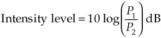
where P1 and P2 are values of acoustical or electrical power.
If the denominator of the ratio is set to a reference value, standard measurements can be made. In acoustic measurements, an intensity level (IL) can be measured in decibels by setting the reference intensity to the threshold of hearing, which is 10−12 W/m2 (watts per square meter). Thus the intensity level of a loud rock band producing sound power of 10 W/m2 can be calculated as:
When ratios of currents, voltages, or sound pressures are used (quantities whose square is proportional to power), the above decibel formula must be multiplied by 2.
The zero reference level for an acoustic sound pressure level measurement is a pressure of 0.0002 dyne/cm2. This level corresponds to the threshold of hearing, the lowest SPL humans can perceive, which is nominally equal to 0 dB SPL. The threshold of feeling, the loudest level before discomfort begins, is 120 dB SPL. Sound pressure levels can be rated on a scale in terms of SPL. A quiet home might have an SPL of 35 dB, a busy street might be 70 dB SPL, and the sound of a jet engine in close proximity might exceed 150 dB SPL. An orchestra’s pianissimo might be 30 dB SPL, but a fortissimo might be 110 dB SPL. Thus its dynamic range is 80 dB.
The logarithmic nature of these decibels should be considered. They are not commonly recognizable, because they are not linear measurements. Two motorcycle engines, each producing an intensity level of 80 dB, would not yield a combined IL of 160 dB. Rather, the logarithmic result would be a 3-dB increase, yielding a combined IL of 83 dB. In linear units, those two motorcycles each producing sound intensities of 0.0001 W/m2 would combine to produce 0.0002 W/m2.
Harmonics
The simplest form of periodic motion is the sine wave; it is manifested by the simplest oscillators, such as pendulums and tuning forks. The sine wave is unique because it exists only as a fundamental frequency. All other periodic waveforms are complex and comprise a fundamental frequency and a series of other frequencies at multiples of the fundamental frequency. Aperiodic complex waveforms, such as the sound of motorcycle engines, do not exhibit this relationship. Many musical instruments are examples of the special case in which the harmonics are related to the fundamental frequency through simple multiples. For example, a complex pitched waveform with a 150-Hz fundamental frequency will have overtones at 300, 450, 600, 750 Hz, and so on.
Overtones extend through the upper reaches of human hearing. The relative amplitudes and phase relationships of those overtones account for the timbre of the waveform. For example, a cello and trumpet can both play a note with the same fundamental pitch; however, their timbres are quite different because of their differing harmonic series. When a cellist plays the note D4 as a natural harmonic, the open D string is bowed, which normally produces a note of pitch D3, and the string is touched at its midpoint. The pitch is raised by an octave because the player has damped out all the odd-numbered harmonics, including the fundamental frequency. The pitch changes; because the harmonic structure changes, the timbre changes as well. Harmonic structure explains why the ear has limited ability to distinguish timbre of high-frequency sounds. The first overtone of a 10-kHz periodic tone is at 20 kHz; most people have trouble perceiving that overtone, let alone others even higher in frequency. Still, to record a complex waveform properly, both its fundamental and harmonic structure must be preserved, at least up to the limit of hearing.
The harmonic nature of periodic waveforms is summarized by the Fourier theorem. It states that all complex periodic waveforms are composed of a harmonic series of sine waves; complex waveforms can be synthesized by summing sine waves. Furthermore, a complex waveform can be decomposed into its sine-wave content to analyze the nature of the complex waveform. A mathematical transform can be applied to a waveform represented in time to convert it to a representation in frequency. For example, a square wave would be transformed into its fundamental sine wave and higher order odd harmonics. An inverse transform reverses the process. Likewise the information in any audio signal can thus be represented in either the time domain or the frequency domain. Some digital audio systems (such as the Compact Disc) code the audio signal as time-based samples. Other systems (such as MP3 players) code the audio signal as frequency coefficients.
Given the evident complexity of acoustical signals, it would be naive to believe that analog or digital audio technologies are sufficiently advanced to fully capture the complete listening experience. To complicate matters, the precise limits of human perception are not known. One thing is certain: at best, even with the most sophisticated technology, what we hear reproduced through an audio system is an approximation of the actual sound.
Digital Basics
Acoustics and analog audio technology are mainly concerned with continuous mathematical functions, but digital audio is a study of discrete values. Specifically, a waveform’s amplitude can be represented as a series of numbers. That is an important first principle, because numbers allow us to manage audio information very efficiently. Using digital techniques, the capability to process information is greatly enhanced. The design nature of audio recording, signal processing, and reproducing hardware has followed the advancement of digital technology; the introduction of software programming into the practical audio environment has been revolutionary. Thus, digital audio is primarily a numerical technology. To understand it properly, let’s begin with a review of number systems.
The basic problem confronting any digital audio system is the representation of audio information in numerical form. Although many possibilities present themselves, the logical choice is the binary number system. This base 2 representation is ideally suited for storing and processing numerical information. Fundamental arithmetic operations are facilitated, as are logic operations.
Number Systems
It all begins with numbers. With digital audio, we deal with information and numbers, as opposed to an analog representation. Numbers offer a fabulous way to code, process, and decode information. In digital audio, numbers entirely represent audio information. We usually think of numbers as symbols. The symbology is advantageous because the numerical symbols are highly versatile; their meaning can vary according to the way we use them.
For example, consider my classic 1962 BMW R50/2 motorcycle, 500 cubic centimeters, registered as 129907, and shown in Fig. 1.1. Several numbers describe this machine; not so obvious is the important context of each. R50/2 represents the motorcycle’s model number, 1962 is the year of manufacture, and 500 represents the quantity of cubic centimeters of engine displacement. The license number 129907 represents coded information that allows my speeding tickets to be properly credited to my account. These various numbers are useful only by virtue of their arbitrarily assigned contexts. If that context is confused, then information encoded by the numbers goes awry. I could end up with a motorcycle with license number 1962, manufactured in the year 500, with an engine displacement of 129907 cubic centimeters.

FIGURE 1.1 The author’s classic 1962 BMW R50/2 motorcycle.
Similarly, the numerical operations performed on numbers are matters of interpretation. The tally of my moving violations determines when my license will be suspended, but the sum of my license plate numerals is less problematic. Numbers, if properly defined, provide a good method for storing and processing data. The negative implication is that numbers and their meanings have to be used carefully.
For most people, the most familiar numbers are those of the base 10 system, apparently devised in the ninth century by Hindu astronomers who conceived of the 0 numeral to represent nothing and appended it to the nine other numerals already in use. Earlier societies were stuck with the unitary system, which used one symbol in a series of marks to answer the essential question: how many? That is an unwieldy system for large numbers; thus, higher-base systems were devised. Babylonian mathematicians invented a number system that used 60 symbols. It was a little cumbersome, but even today, 3700 years later, the essence of their system is still used to divide an hour into 60 minutes, a minute into 60 seconds, and a circle into 360 degrees.
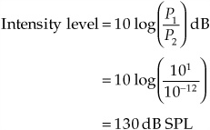
Selection of a number system is a question of preference, because any integer can be expressed using any base. Choosing a number system simply questions how many different symbols we think are most convenient. The base 10 system uses 10 numerals; the radix of the system is 10. In addition, the system uses positional notation; the position of the numerals shows the quantities of ones, tens, hundreds, thousands, and so on. In other words, the number in each successive position is multiplied by the next higher power of the base. A base 10 system is convenient for 10-fingered organisms such as humans, but other number bases might be more appropriate for other applications. In any system, we must know the radix; the numeral 10 in base 10 represents the total number of fingers you have, but 10 in base 8 is the number of fingers minus the thumbs. Similarly, would you rather have 10,000 dollars in base 6, or 100 dollars in base 60? Table 1.1 shows four of the most popular number systems.
Binary Number System
Gottfried Wilhelm von Leibnitz, philosopher and mathematician, devised the binary number system on March 15, 1679. That day marks the origin of today’s digital systems. Although base 10 is handy for humans, a base 2, or binary, system is more efficient for digital computers and digital audio equipment. Only two numerals are required to satisfy the machine’s principal electrical concern of voltage being on or off. Furthermore, these two conditions can be easily represented as 0 and 1; these binary digits are called bits (binary digits). From a machine standpoint, a binary system is ruthlessly efficient, and it is fast. Imagine how quickly we can turn a switch on and off; that speed represents the rate at which we can process information. Imagine a square wave; the wave could represent a machine operating the switch for us. Consider the advantages in storage. Instead of saving infinitely different analog values, we must only remember two values. Only through the efficiency of binary data can digital circuits process the tremendous amount of information contained in an audio signal.
Whatever information is being processed—in this case, an audio signal that has been converted to binary form—no matter how unrelated it might appear to be to numbers, a digital processor codes the information in the form of numbers, using the base 2 system. To better understand how audio data is handled inside a digital audio system, a brief look at the arithmetic of base 2 will be useful. In fact, we will consistently see that the challenge of coding audio information in binary form is a central issue in the design and operation of digital audio systems.
TABLE 1.1 Four common number systems.
In essence, all number systems perform the same function; thus, we can familiarize ourselves with the binary system by comparing it to the decimal system. A given number can be expressed in either system and converted from one base to another. Several methods can be used. One decimal-to-binary conversion algorithm for whole numbers divides the decimal number by 2 and collects the remainders to form the binary number. Similarly, binary-to-decimal conversion can be accomplished by expressing the binary number in a power of 2 notation, then expanding and collecting terms to form the decimal number.
The conversion points out the fact that the base 2 system also uses positional notation. In base 2, each successive position represents a doubling of value. The right-most column represents 1s, the next column is 2s, then 4s, 8s, 16s, and so on. It is important to designate the base being used; for example, in base 2 the symbol 10 could represent a person’s total number of hands.
Just as a decimal point is used to delineate a whole number from a fractional number, a binary point does the same for binary numbers. The fractional part of a decimal number can be converted to a binary number by multiplying the decimal number by 2. Conversion often leads to an infinitely sustaining binary number, so the number of terms must be limited.
As in the base 10 system, the standard arithmetic operations of addition, subtraction, multiplication, and division are applicable to the base 2 system. As in any base, base 2 addition can be performed using the addition rules needed to form an addition table. The procedure is the same as in the decimal system; however, the addition table is simpler. There are only four possible combinations, compared to the more than 100 possible combinations resulting from the rules of decimal addition. The generation of the carry, as in the decimal system, is necessary when the result is larger than the largest digit in the system. The algorithms for subtraction, multiplication, and division in the binary system are identical to the corresponding algorithms in the decimal system.
Binary numbers are unwieldy for humans, so we often represent them as base 16 (hexadecimal) numbers. Hexadecimal numbers use numerals 0 through 9 and A, B, C, D, E, F (0 to 15 in decimal), and each hexadecimal number can represent four binary digits (see Table 1.1). Thus an 8-bit byte can be represented by 2 hex digits. For example, the value 0110 1110 would be represented as 6E.
A number is what we make it, and the various systems—differing only by base—operate in essentially the same way. A computer’s use of the binary system is a question of expediency; it presents no real barrier to an understanding of digital techniques. It is simply the most logical approach. Ask yourself, would you rather deal with 10, 60, an infinite analog number, or 2 voltage levels? Fortunately, most digital systems automatically choose the best of both number-base worlds; you punch base-10 numbers into a calculator, it uses base 2 to perform its operations, then displays the result in base 10.
Binary Codes
Although the abstractions of binary mathematics form the basis of digital audio systems, the implementation of these primitives requires higher-level processing. Specifically, the next step up the evolutionary ladder is the coding of binary information. For example, individual binary bits or numbers can be ordered into words with specific connotations attached. In this way, both symbolic and numeric information are more easily processed by digital systems.
Just as the digits in a motorcycle license number carry a specially assigned meaning, groups of binary numbers can be encoded with special information. For example, a decimal number can be converted directly to its equivalent binary value; the binary number is encoded as the binary representation of the decimal number. Obviously, there is a restriction on the number of possible values that can be encoded. Specifically, an n-bit binary number can encode 2n numbers. Three bits, for example, could encode eight states: 000, 001, 010, 011, 100, 101, 110, and 111. These could correspond to the decimal numbers 0, 1, 2, 3, 4, 5, 6, and 7.
Negative numbers present a problem because the sign must be encoded (with bits) as well. For example, a 1 in the left-most position could designate a negative number, a 0 could designate a positive number, and the remaining bits could represent the absolute value of the number. This kind of coding is called a signed-magnitude representation. The 3-bit words 000, 001, 010, 011, 100, 101, 110, and 111 might correspond to +0, +1, +2, +3, −0, −1, −2, and −3. An irregularity is the presence of both +0 and −0. Other methods can be used to better represent negative numbers.
Because we live in a decimal world, it is often useful to create binary words coded to decimal equivalents, preserving the same kind of decimal characteristics. Unfortunately, there is no binary grouping that directly represents the 10 decimal digits. Three bits handle the first seven decimal numbers, and four bits handle 16. For greater efficiency, a more sophisticated coding method is desirable. This method is easily accomplished with groups of four bits each, with each group representing a decimal digit:
![]()
Given this approach, there are many ways that the 10 decimal digits can be encoded as 4-bit binary words. It makes sense to find a method that provides as many benefits as possible. For example, a good code should facilitate arithmetic operations and error correction, and minimize storage space and logic circuitry. Similarly, whenever digital audio designers select a coding method, they examine the same criteria.
Weighted Binary Codes
In some applications, weighted codes are more efficient than other representations. In a weighted code, each binary bit is assigned a decimal value, called a weight. Each number represented by the weighted binary code is calculated from the sum of the weighted digits. For example, weights w3, w2, w1, w0 and bits a3, a2, a1, a0 would represent the decimal number N = w3 × a3 + w2 × a2 + w1 × a1 + w0 × a0.
The binary coded decimal (BCD) code is commonly used in digital applications. BCD is a positional weighted code in which each decimal digit is binary coded into 4-bit words. It is sometimes called the 8-4-2-1 code, named after the values of its weights. The BCD representation is shown in Table 1.2, along with several other binary codes. The 8-4-2-1 and 6-3-1-1 codes are weighted; the others are not. Any decimal number can be represented with the BCD code. For example, the number 5995 would be 0101 1001 1001 0101. Note that the resulting binary number is quite different from that obtained by direct decimal-to-binary conversion. The BCD code solves the binary problem of representing large decimal numbers; systems interfacing with decimal numbers often use BCD code for this reason. Thus, they incorporate binary-to-BCD, and BCD-to-binary conversion programs. The 6-3-1-1 code is another example of a weighted code. For example, using the weights assigned to the 6-3-1-1 code, the codeword 1001 represents the decimal number N = 6 × 1 + 3 × 0 + 1 × 0 + 1 + 1 = 7.
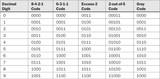
TABLE 1.2 Examples of several binary codes. The 8-4-2-1 and 6-3-1-1 codes are weighted; the others are unweighted.
Unweighted Binary Codes
In some applications, unweighted codes are preferred. Several examples of unweighted codes are excess-3, 2-out-of-5, and Gray code. The excess-3 code is derived from the 8-4-2-1 code by adding 3 (0011) to each codeword. In other words, the decimal digit d is represented by the 4-bit binary number d + 3. In this way, every codeword has at least one 1. The 2-out-of-5 code is defined so that exactly two out of the five bits are 1 for every valid word. This definition provides a simple way to check for errors; an error could result in more or less than two 1s.
Other unweighted codes can be defined, for example, so that no codeword has less than one 1 or more than two 1s. This minimizes transitions in logic states when changing words, a potential cause of errors or distortion in output circuitry. In a Gray code, sometimes called a reflected code system, only one digit can change value when counting from one state to the next. A disadvantage of an unweighted code is that generally the corresponding decimal value cannot be easily computed from the binary values.
Two’s Complement
Although it is comforting to define binary operations in terms familiar to humans, clearly such an enterprise would not be expedient. It makes more sense to specify numbers and operations in ways most easily handled by machines. For example, when binary numbers are stored in complemented form, an adding operation can be used to perform both addition and subtraction. Furthermore, when binary numbers are stored and processed through registers, a modular number system is often preferable.
Simple binary arithmetic operations can present problems when the result is stored. For example, given a 3-bit system, suppose the numbers 110 and 100 are added. The answer is 1010. The left-most bit is a carry digit from the addition process. However, in a 3-bit system, the carry digit would be lost, and the remaining answer would be 010. This is problematic unless the system can identify that an overflow has occurred. With modular arithmetic, such a result is easily reconciled.
Overflow is inherent in any system with a finite number of digits. Overflow requires an adjustment in our thinking. When an infinite number of digits is available, the task of adding, for example, 6 and 4 could be visualized by joining two straight line segments of lengths 6 and 4 together to obtain a line segment of 10. However with a finite number of digits, it is better to visualize a circular system. For example, when we add 610 (1102) and 410 (1002), the appropriate circular segments are joined, leading to a result of 210 (0102). The resulting number 2 is the remainder obtained by subtracting 8, that is (23), from the sum of 10. Two numbers A and B are equivalent in modulo N if A divided by N yields a remainder that equals the remainder obtained when B is divided by N. For example, if A = 12 and B = 20, then A = B (mod 8) because 12/8 = 1 + remainder 4 and 20/8 = 2 + remainder 4. The remainders are equal, thus the numbers are equivalent in modulo 8. Modulo 2 arithmetic is used in many binary applications; in general, when performing numerical operations with n-bit words, modulo 2n arithmetic is used.
As noted, negative numbers can be expressed in binary form with a sign bit. Although convenient for humans, it is illogical for machines. Independent circuits would be required for addition and subtraction. Instead, using a special property of modulo number systems, an addition operation can be used to perform subtraction as well. Although a carry operation is still required, a borrow is not. Specifically, rather than store a negative number as a sign and magnitude, it can be coded in a base-complemented form. Two kinds of complements exist for any number system. A radix-minus-one complement is formed by subtracting each digit of the number from the radix-minus-one of the number system. This is known as the nine’s complement in the decimal system and the one’s complement in the binary system. A true complement is formed by subtracting each digit of the number from the radix-minus-one, then adding 1 to the least significant digit. The true complement is called the ten’s complement in the decimal system, and the two’s complement in the binary number system. With base complement, a number added to an existing number results in the full next power of the base. For example, the ten’s complement of 35 is 65 because 35 + 65 = 102 = 100, and the two’s complement of 1011 is 0101 because 1011 + 0101 = 24 = 10000. From this, note that a complement is the symbol complement plus 1, and the symbol complement is found by subtracting the original number from the highest symbol in the system.
Forming the one’s and two’s complements in the binary system is easily accomplished and expedites matters tremendously. Because the radix is 2, each bit of the binary number is subtracted from 1. Thus, a one’s complement is formed by replacing 1s by 0s, and 0s by 1s, that is, complementing the digits. The two’s complement is formed by simply adding 1 to that number and observing any carry operations. For example, given a number 0100, its one’s complement is 1011, and its two’s complement is 1100. It is the two’s complement, formed from the one’s complement, that is most widely used. For example, Table 1.3 shows a representation of numbers from +7 to −7 with two’s complement representation of negative numbers. A positive two’s complement number added to its negative value will always equal zero.
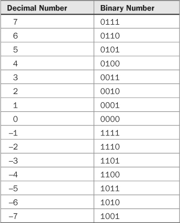
TABLE 1.3 A table of values showing a two’s complement representation of positive and negative numbers.
Recalling the discussion of modulo number systems, we observe how subtraction can be replaced by addition. If A + B = 0 in a modulo system N, then B is the negative of A. There are in fact many Bs such that B = kN − A where k = 0, 1, 2, . . . . When k = 1 and A is less than N, then B = N − A behaves as a positive number less than N. We can use B = N − A in place of −A in any calculation in modulo N. For example, C = D − A is equivalent to C = D + (N − A). In other words, if we can obtain N − A without performing subtraction, then subtraction can be performed using addition. After some thought on the matter, we observe that, conveniently, N− A is the two’s complement of A.
Complement subtraction can be performed with addition. With binary, first consider standard subtraction:

However, the same operation can be performed by adding the two’s complement of the subtrahend:
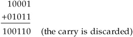
When a larger number is subtracted from a smaller one, there is no carry. For example, 2 − 8 becomes 2 + (10 − 8) or 2 + 2 = 4. Notice that the answer 4 is the ten’s complement of the negative result that is −(10 − 4) = −6. Similarly, when a larger number is subtracted from a smaller one in binary:

In two’s complement:

The answer is negative, but in two’s complement form. Taking the two’s complement and assigning a negative sign results in the number −10110. When performing two’s complement subtraction, the final carry provides the sign of the result. A final carry of 1 indicates a positive answer, and a carry of 0 indicates a negative answer, in its two’s complement, positive form.
If base complementing seems tedious, it is redeemed by its advantages when handling positive and negative (bipolar) numbers, which might, for example, represent an audio waveform. The most significant bit (MSB) is the sign bit. When it is 0, the number is positive, and when it is 1, the number is negative. In true binary form, the number 5 can be represented by 00000101 and −5 by 10000101. By representing negative numbers in two’s complement form, −5 becomes 11111011, and the sign is handled automatically. All additions and subtractions will result in positive numbers in true binary form and all negative numbers in two’s complement form, with the MSB automatically in the proper sign form. Humans appreciate two’s complement because the left digit always denotes the sign. Digital processors appreciate it because subtraction can be easily performed through addition.
Boolean Algebra
The binary number system presents tremendous opportunities for the design of electronic hardware and software, including, of course, digital audio applications. Boolean algebra is the method used to combine and manipulate binary signals. It is named in honor of its inventor, George Boole, who published his proposal for the system in 1854 in a book entitled An Investigation of the Laws of Thought, on Which Are Founded the Mathematical Theories of Logic and Probabilities. Incidentally, historians tell us that Boole’s formal education ended in the third grade. Also, the lunar crater Boole is named after him.
Boolean logic is essential to digital applications because it provides the basis for decision making, condition testing, and performing logical operations. Using Boolean algebra, all logical decisions are performed with the binary digits 0 and 1, a set of operators, and a number of laws and theorems. The on/off nature of the system is ideally suited for realization in digital systems. The set of fundamental logic operators provides the tools necessary to manipulate bits and hence design the logic that comprises useful digital systems. Everything from vending machines to super computers can be designed with this powerful mathematics. It was Claude Shannon, introduced to Boolean logic in a philosophy class, who first used Boolean algebra to establish the theory of digital circuits.
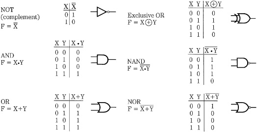
FIGURE 1.2 The six basic Boolean operators can be used to manipulate logical conditions.
The Boolean operators are shown in Fig. 1.2. The operators OR, AND, AND EXCLUSIVE OR (XOR) combine two binary digits to produce a single-digit result. The Boolean operator not complements a binary digit. NAND and NOR are derived from the other operators. The operators can be used singly or in combinational logic to perform any possible logical operation.
The NOT operation complements any set of digits. The complement of 0 is 1, and the complement of 1 is 0. A bar is placed over the digit to represent a complement.
The AND operation is defined by the statement: If X AND Y are both 1, then the result is 1; otherwise the result is 0. Either a dot symbol or no symbol is used to denote AND.
The OR operation is defined by the statement: If X OR Y, or both, are 1 then the result is 1; otherwise the result is 0. A plus sign is usually used to denote OR.
EXCLUSIVE OR differentiates whether binary states are the same or different. Its output is 1 when X differs from Y, and is 0 when X is the same as Y. Importantly, the XOR function thus performs modulo 2 binary addition. A circled plus sign is used to denote XOR.
Combining AND and NOT produces NAND, and combining OR and NOT produces NOR; their results are the NOT of AND and OR, respectively.
The Boolean operators can be combined into meaningful expressions, giving statement to the condition at hand. Moreover, such statements often lead to greater insight of the condition, or its simplification. For example, a digital system needs only the or and not functions because any other function can be derived from those functions. This relationship can be shown using De Morgan’s theorem, which states:

Using De Morgan’s theorem, observe that the expression:
![]()
generates AND from OR and NOT, and the expression:
![]()
generates XOR from OR and NOT.
This example shows that Boolean operators can be combined into expressions. In this case, De Morgan’s theorem is used to form the complement of expressions. This ability to form logical expressions allows us to use Boolean operators, along with one or more variables or constants, to solve applications problems. Parentheses are used to define the order in which operations are performed; operations are initiated within parentheses. When parentheses are omitted, complementation is performed first, followed by and AND then OR.
Logical expressions correspond directly to networks of logic gates, realizable in hardware or software. For example, Fig. 1.3A shows a logical expression and its equivalent network of logic gates. An expression can be evaluated by substituting a value of 0 or 1 for each variable, and carrying out the indicated operations. Each appearance of a variable or its complementation is called a literal.
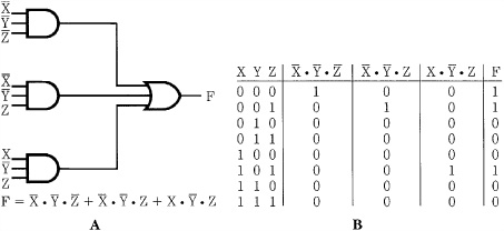
FIGURE 1.3 Boolean expressions can be realized through hardware or software, as circuits or logical statements. A. The logic realization of a Boolean expression. B. A truth table verifying the solution to the Boolean expression.
A truth table, or table of combinations, can be used to illustrate all the possible combinations contained in an expression. In other words, the output can be expressed in terms of the input variables. For example, the truth table in Fig. 1.3B shows the results of the logic circuit in Fig. 1.3A.
Given a set of operators and ways to combine them into expressions, the next step is to develop a system of Boolean algebraic relations. That set forms the basis of digital processing in the same way that regular algebra governs the manipulation of the familiar base 10 operations. In fact, the base 2 and base 10 algebraic systems are very similar, to the point of confusion. Relations such as complementation, commutation, association, and distribution form the mathematical logic needed to create logical systems. These laws hold true for Boolean algebra, but they are often uniquely defined.
Double complementation results in the original value. In other words, if 1 is complemented it becomes 0, and when complemented again, it becomes 1 again. Commutative laws state that the order in which terms are combined (with addition and multiplication operators) does not affect the result. Associative laws state that when several terms are added or multiplied, the order of their selection for the operation is immaterial. Distributive laws demonstrate that the product of one term multiplied by a sum term equals the sum of the products of the first term multiplied by each product term.
Using Boolean theorems and other reduction theorems, such as De Morgan’s theorem, complex logical expressions can often be untangled to provide simple results. For example, consider these expressions:

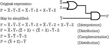
FIGURE 1.4 Complex logical expressions can be simplified with Boolean laws to permit simpler hardware or software realization.
All these functions call for different Boolean manipulations, but their outputs are identical. Whether the end result of an expression is a hardware circuit or software program, simplification is understandably critical. For example, Boolean algebra can be applied to the expression in Fig. 1.3, resulting in a much simpler expression, as shown in Fig. 1.4. In this case, the original circuit required three AND gates, one OR gate, and three NOT circuits. The simplified circuit requires one AND, one OR, and two NOTS. The important point is that both circuits perform the same function, with identical outputs for any possible inputs.
Using these tools, useful digital hardware and software can be conceived to manage information or perform processing. More generally, Boolean algebra can be applied to many types of problems. Even word problems posed in English can be converted to Boolean form and solved. For example, consider the syllogism (by Lewis Carroll) with these three premises:
1. All babies are illogical.
2. Nobody is despised who can manage a crocodile.
3. Illogical persons are despised.
By applying the principles of symbolic logic, the absolutely logical conclusion is:
4. A person able to manage a crocodile is not a baby.
Whether the problem involves babies, crocodiles, motorcycle engines, or violin tones, binary logic can be applied with great finesse when the problem can be reduced to a binary state. From that elemental simplicity, tremendous complexity can be achieved. In this respect, all digital systems are alike. They differ, however, according to the kinds of information they process and what data manipulations they are called upon to accomplish. A digital audio system is thus a unique digital system, which is specially configured to process audio data. Nonintuitively, digital audio systems have more in common with syllogisms than they do with analog audio systems.
Analog versus Digital
Digital audio entails entirely new concepts and techniques, distinct from those employed in analog technology. From the very onset, we must think of information and its storage and processing in a new light. In that respect, a few comparisons between analog and digital technology might be helpful in showing the vast differences between them, as well as some of the advantages and disadvantages of each technology.
An analog signal can be compared to a digital signal; consider a bucket of water compared to a bucket of ball bearings. Both water and ball bearings fill their respective containers. The volume of each bucket can be characterized by measuring its contents, but the procedures for each bucket would be different. With water, we could weigh the bucket and water, pour out the water, weigh the bucket alone, subtract to find the weight of the water, then calculate the volume represented. Or we could dip a measuring cup into the bucket and withdraw measured amounts. In either case, we run the risk of spilling some water or leaving some at the bottom of the bucket; our measurement would be imprecise.
With a bucket of ball bearings, we simply count each ball bearing and calibrate the volume of the bucket in terms of the number of ball bearings it holds. The measurement is relatively precise, if perhaps a little tedious (we might want to use a computer to do the counting). The ball bearings represent the discrete values in a digital system, and demonstrate that with digital techniques we can quantify the values and gain more accurate information about the measurement. In general, precision is fundamental to any digital system. For example, a bucket that has been measured to hold 1.6 quarts of water may be less useful than a bucket that is known to hold 8263 ball bearings. In addition, the counted ball bearings provide repeatability. We might fill another bucket with water, but that bucket might be a different size and we could easily end up with 1.5 quarts. On the other hand, we could reliably count out 8263 ball bearings anywhere, anytime.
The utility of a digital system compared to an analog system is paradoxical. Conceptually, the digital system is much simpler, because counting numbers is easier than measuring a continuous flow. That is, it is easier to process a representation of a signal rather than process the signal itself. However, in practice, the equipment required to accomplish that simple task must be more technologically sophisticated than any analog equipment.
The comparison between analog and digital audio can be simply summarized. An analog signal chain, from recording studio to living room, must convey a continuous representation of amplitude change in time. This is problematic because every circuit and storage medium throughout the chain is itself an analog device, contributing its own analog distortion and noise. This unavoidably degrades the analog signal as it passes through. In short, when an analog signal is processed through an analog chain with inherent analog artifacts, deterioration occurs. In addition, it is worth noting that analog systems tend to be bulky, power hungry, prone to breakdown, and cannot be easily modified to perform a different task.
With digital audio, the original analog event is converted into a quantity of binary data, which is processed, stored, and distributed as a numerical representation. The reverse process, from data to analog event, occurs only at playback, thus eliminating many occasions for intervening degradation. The major concern lies in converting the analog signal into a digital representation, and back again to analog. Nevertheless, because the audio information is carried through a numerical signal chain, it avoids much spurious analog distortion and noise. In addition, digital circuits are less expensive to design and manufacture, they offer increased noise immunity, age immunity, temperature immunity, and greatly increased reliability. Even more important, the power of software algorithms can flexibly process numerically represented audio signals, yielding precise and sophisticated results.
In theory, digital audio systems are quite elegant, suggesting that they easily surpass more encumbered analog systems. In practice, although digital systems are free of many analog deficiencies, they can exhibit some substantial anomalies of their own. The remaining chapters only scratch the surface of the volume of knowledge needed to understand the complexities of digital audio systems. Moreover, as with any evolving science, every new insight only leads to more questions.