
CHAPTER 7
Compact Disc
The introduction of the Compact Disc (CD) system was perhaps the most remarkable development in audio technology since the birth of audio recording technology in 1877 with Edison’s invention of the tinfoil recorder. The Compact Disc system contains numerous technologies original to the audio field; when combined, these technologies formed a storage means that was unprecedented at its invention.
A Compact Disc contains digitally encoded data that is read by a laser beam. Because the reflective data layer is embedded within the disc, dust and fingerprints on the reading surface do not normally affect reproduction. The effect of most errors can be minimized by error-correction algorithms. Because no stylus touches the disc surface, there is no disc wear, no matter how often the disc is played. Thus, digital storage, error correction, and disc longevity result in a robust digital storage medium. In addition, the CD offers high-density data storage providing long playing time with a small disc size. Whereas the (analog) Edison cylinder stored the equivalent of 100 bits/mm2, the CD stores about 1 million bits/mm2. Above all, the CD established a new fidelity standard that was unprecedented for the consumer with flat frequency response and low distortion. In addition, the CD is highly effective for storing other types of data beyond digital music. But as impressive as the CD is, it is surpassed by its optical disc successors, the Super Audio CD, DVD, and Blu-ray formats.
Development
The chronology of events in the development of the Compact Disc spans almost a decade from inception to introduction. Even then, the development of optical disc storage predates the CD by several more decades. The CD incorporates many technologies pioneered by many individuals and corporations; however, Philips Corporation of The Netherlands and Sony Corporation of Japan must be credited with its primary development. Optical disc technology developed by Philips and error-correction techniques developed by Sony, when merged, resulted in the successful CD format. The original standard established by these two companies guarantees that discs and players made by different manufacturers are compatible. The CD-Audio or CD-DA (Compact Disc Digital Audio) format is sometimes called the Red Book standard (after the color of the notebook used to hold the original specification); it was formalized in 1980. In 1987, it was subsequently also specified in the IEC 908 standard (International Electrotechnical Commission) available from the American National Standards Institute (ANSI).
Philips began working on optical disc storage of images in 1969. It first announced the technique of storing audio material optically in 1972. Analog modulation methods used for video storage were deemed unsuitable, and the possibility of digital signal encoding was examined. Furthermore, Philips established laser readout and small disc diameter as a design prerequisite. Sony, similarly had explored the possibility of an optical, large-diameter audio disc, and had extensively researched the error-processing and channel-coding requirements for a practical realization of the system. Other manufacturers such as Mitsubishi, Hitachi, Matsushita, JVC, Sanyo, Toshiba, and Pioneer advanced proposals for a digital audio disc. By 1977, numerous manufacturers had shown prototype optical disc audio players. In 1978, Philips and Sony designated disc characteristics, signal format, and error-correction methods; and in 1979 they reached an agreement in principle to collaborate (with design meetings from August 1979 through May 1980) with decisions on signal format and disc material. In June 1980, they jointly proposed the Compact Disc Digital Audio system, which was subsequently adopted by the Digital Audio Disc Committee, a group representing more than 25 manufacturers.
Following the development of a semiconductor laser pickup and LSI (large-scale integration) circuits for signal processing and digital-to-analog conversion, the Compact Disc system was introduced in October of 1982 in Japan and Europe. In March 1983, the Compact Disc was made available in the United States. Over 350,000 players and 5.5 million discs were sold worldwide in 1983, and 900,000 players and 17 million discs in 1984, making the CD one of the most successful electronic product launches ever. Starting with the original CD-Audio format, the CD family was expanded to include CD-ROM (1984), CD-i (1986), CD-WO (1988), Video-CD (1994), and CD-RW (1996) with a host of applications in data, audio, and video. The SACD, introduced in 1999, incorporates aspects of the CD.
Overview
The Compact Disc is an efficient information storage system. An audio disc stores a stereo audio signal comprising two 16-bit data words sampled at 44.1 kHz; thus, 1.41 million bits per second (Mbps) of audio data are output from the player along with other nonaudio data. Altogether, the channel bit rate, the rate at which data is read from the disc, is 4.3218 Mbps. A disc containing an hour of music thus holds about 15.5 billion channel bits—a respectable capacity for a disc that costs a few cents to manufacture. Apart from overhead (33% for error correction, 7% for synchronization, and 4% for control and display), a CD-Audio disc holds a maximum of 6.3 billion bits, or 783 million bytes of user information.
A standard Compact Disc measures 12 cm in diameter and has a maximum playing time of 74 minutes, 33 seconds. By varying the CD standards slightly, longer playing times can be achieved. For example, a track pitch of 1.5 m and a linear velocity of 1.2 m/s would yield a playing time of about 82 minutes.
Information is contained in a pit track impressed into one side of the disc’s plastic substrate. The substrate is made of polycarbonate plastic (also used for eyeglass lenses). The data surface is metallized to reflect the laser beam used to read the data from underneath the disc. A pit is about 0.6 μm wide (it is worth remembering that a micrometer [1 micron] equals 1-millionth of a meter, or about 40 millionths of an inch) and a disc might hold about 2 billion pits. If a disc were enlarged so that its pits were the size of grains of rice, the disc would be half a mile in diameter. Along the track, each pit edge represents a binary 1; flat areas between pits or areas within pits are decoded as binary 0s. Data is read from the disc as a change in intensity of reflected laser light. Reading a CD causes no more wear to the recording than your reading causes to the words printed on this page (also conveyed to your eyes via reflected light).
The pits are aligned in a spiral track running from the inside radius of the disc to the outside. CDs with maximum playing times contain data to within 3 mm of the outer disc edge. CDs with shorter playing times have an unused area at the outer edge. This allows a greater manufacturing yield because errors tend to increase at the outer radius, and the disc is oblivious to fingerprints on the empty outer radius. If unwound, a CD track would run for about 3.5 miles. The pitch (distance between adjacent track revolutions) of the CD spiral is nominally 1.6 μm. There are 22,188 track revolutions across the disc’s signal surface of 35.5 mm. The period at the end of this sentence would cover more than 200 tracks.
Data is retrieved with an optical pickup. A laser beam is emitted and is guided through optics to the disc data surface. The reflected light is detected by the pickup, and the data from the disc conveyed on the beam is converted to an electrical signal. Because nothing touches the disc except light, light itself and electrical servo circuits are used to keep the laser beam properly focused on the disc surface and properly aligned with the spiral track. The pits are encoded with eight-to-fourteen modulation (EFM) for greater storage density and Cross-Interleave Reed–Solomon code (CIRC) for error correction; algorithms in players provide demodulation and error correction. When the audio data has been properly recovered from the disc and converted into a binary signal, it is input to digital oversampling filters and digital-to-analog converters to reconstruct the analog signal.
Music CDs deliver high-fidelity sound with excellent performance specifications. With 16-bit quantization sampled at 44.1 kHz, players typically exhibit a frequency response of 5 Hz to 20 kHz with a deviation of 0.2 dB. Dynamic range exceeds 100 dB, signal-to-noise ratio exceeds 100 dB, and channel separation exceeds 100 dB at 1 kHz. Harmonic distortion at 1 kHz is typically less than 0.002%. Rotational speed deviation is limited to the tolerances of quartz accuracy, which is essentially unmeasurable. With digital filtering, phase shift is less than 0.5°. D/A converters provide linearity to within 0.5 dB at -90 dB. Excluding unreasonable abuse, a disc will remain in satisfactory playing condition indefinitely, as the medium does not significantly age. Electrical measurements of CD players may be carried out with a variety of techniques, such as those described in the AES17 specification.
One might reasonably ask why 44.1 kHz was selected as the sampling frequency for the Compact Disc. Professional video recorders were originally used to prepare CD master tapes because they were the only recorders capable of handling the high bandwidth requirements of digital audio signals. Because 16-bit digital audio signals (and error correction) were encoded as a video signal, the sampling frequency had to relate to television standards’ line and field rate, storing a few samples per scan line. The NTSC (National Television Systems Committee) format used 525 lines in 30 frames per second; only 490 are available for storage. With two samples per line, 490 × 30 × 2 = 29.4 kHz, a too-low sampling frequency. With four samples per line, 490 × 30 × 4 = 58.8 kHz, was considered too high. With three samples per line, 490 × 30 × 3 = 44.1 kHz—it is just right. Moreover, the PAL/SECAM (phase-alteration line/sequential-and-memory) format used 625 lines (588 active lines) in 25 frames per second, and 588 × 25 × 3 = 44.1 kHz as well. Therefore, 44.1 kHz became the universal sampling frequency for CD master tapes. Because sampling-frequency conversion was difficult, and 44.1 kHz was appropriate, the same sampling frequency was used for finished discs.
Disc Design
The CD provides reasonable data density using a combination of the optical design of the disc and the method of coding the data impressed on it. For example, the wavelength of the reading laser and numerical aperture of the objective lens are selected to achieve a small spot size. This allows small pit/land dimensions. In addition, the pit/land track uses a constant linear velocity, and that velocity is set low, to increase the track’s linear data density. Also, EFM is used to encode the stored data. Although it creates more channel bits to be stored, the net result is a 25% increase in audio data capacity.
Disc Optical Specification
The Red Book specifies both the physical and logical characteristics of a Compact Disc. The physical characteristics of a CD are shown in Fig. 7.1. Disc diameter is 120 mm, center hole diameter is 15 mm, and disc thickness is 1.2 mm. The innermost part of the disc does not hold data; it provides a clamping area for the player to hold the disc firmly to the spindle motor shaft. Data is recorded on an area that is 35.5 mm wide. A lead-in area rings the innermost data area, and a lead-out area rings the outermost area. The lead-in and lead-out areas contain nonaudio data used to control the player.
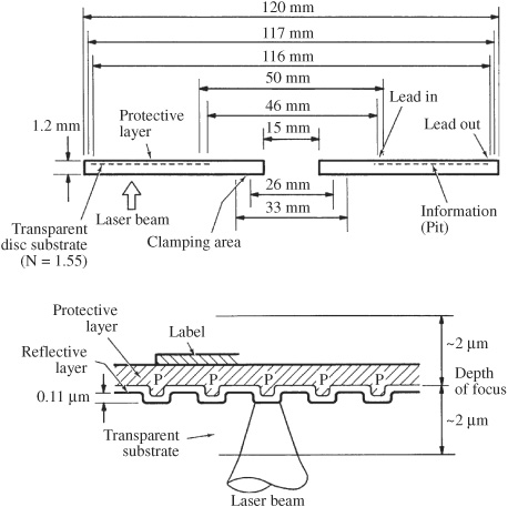
FIGURE 7.1 Physical specification of the Compact Disc showing disc dimensions and the relief structure of data pits.
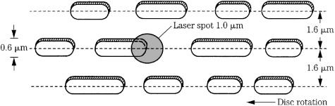
FIGURE 7.2 Data pits are aligned along a spiral track. The laser spot on the data surface has a diameter of approximately 1.0 μm (half-intensity level of the Airy pattern), covering the 0.6-μm pit width.
A transparent plastic substrate forms most of a disc’s 1.2-mm thickness. Data is physically contained in pits that are impressed along its top surface and are covered with a very thin (50 nm to 100 nm) metal (typically aluminum) layer. Another thin (10 μm to 30 μm) plastic layer protects the metallized pit surface, on top of which the identifying label (5 μm) is printed.
The laser beam used to read data operates at a wavelength of 780 nm. The beam is applied from below the disc and passes through the transparent substrate and back again. The velocity of light decreases when it passes from air to the substrate. The substrate has a refractive index of 1.55 (as opposed to 1.0 for air); the velocity of light slows from 3 × 10⁵ km/s to 1.9 × 10⁵ km/s. When the velocity of light slows, the beam refracts, and focusing occurs. Because of the wavelength of the laser light, refractive index, thickness of the disc, and numerical aperture of the laser lens, the approximately 800-μm diameter of the laser beam on the disc surface is focused to a spot measuring approximately 1.0 μm in diameter (Airy pattern half-intensity level) at the pit surface. The CD is diffraction-limited; that is, the choices of the wavelength of the laser light and numerical aperture of the lens will not permit a smaller spot size.
The laser beam is thus focused to a spot that is slightly larger than the 0.6-micron pit width, as shown in Fig. 7.2. The effects of dust or scratches on the substrate’s outer surface are minimized because their size at the data surface is effectively reduced along with the laser beam. Specifically, any obstruction less than 0.5 mm is insignificant and causes no error in the readout. On the other hand, because the disc substrate is part of the playback optics, its optical quality, in terms of birefringence and thickness, must be specified. In addition, because of the relatively large distance between the objective lens and the data surface, disc tilt can cause an error in refraction angle.
Data is physically stored as a phase structure, a metallized surface comprising pits and land. In theory, when the beam strikes the land between pits, virtually all of its light is reflected, and when it strikes a pit, virtually all of its light is canceled, so that virtually none is reflected. As noted in Chap. 6, complete destructive interference in the reflected beam results when the pit depth is such that the intensity of light reflected from a pit equals the intensity of light reflected from the surrounding land, as shown in Fig. 7.3. Specifically, the phase difference forms a diffraction pattern in the reflected light; this causes destructive interference in the main reflected beam. A pit thus reduces the intensity of the reflected light returning to the objective lens. A plane wave model suggests that pit height should be /4 where is the apparent wavelength of light. The model predicts that a pit height equal to /4 creates a phase difference of /2 (1/4 + 1/4 wave-length path differences) between the part of the beam reflected from the pit and the part reflected from the surrounding land. However, a more complex spherical wave model that accounts for effects of the converging focused beam predicts that the optimum pit depth should be /2.
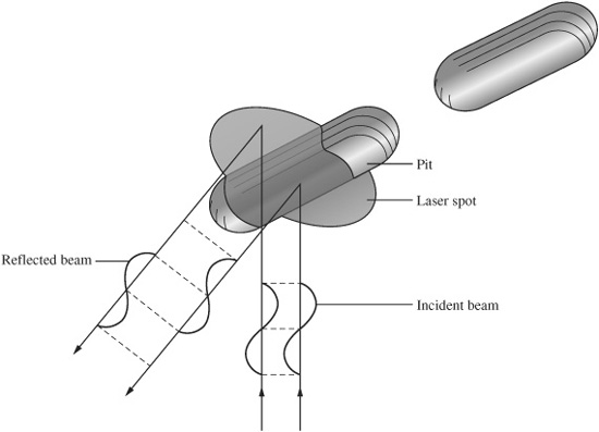
FIGURE 7.3 The laser spot reads data as an intensity modulation of its reflected beam. The phase structure of the data surface places the pit height above the land surface; this creates destructive interference in the reflected beam.
In either case, destructive interference causes an absence of reflected light when there is a pit, distinguishing it from the almost total reflection when the spot strikes the land between pits. In practice, a balance must be made between the data readout advantages of zero reflected pit light, and the reflected intensity that is conducive for signal tracking which requires a /8 pit depth for most pickups. In fact, the specifications for both pit depth and width are a compromise among several factors including optimal high-frequency readout signal, optimal radial tracking signal, and allowance for mass replication. For example, the readout signal should provide good contrast between pit and land areas, but for tracking, the reflected light should not be completely extinguished during a long pit. Moreover, pit geometry must allow the disc to be released from the mold. In practice, pits are made shallower than the theoretically optimal figure and the laser spot is larger than is required for complete cancellation between pit and land reflections. Most CD pressing plants use a pit depth that is approximately one-quarter of the laser’s wavelength in the substrate. The laser beam’s wavelength in air is 780 nm. Inside the polycarbonate substrate, with a refractive index of 1.55, the laser’s wavelength is about 500 nm. Generally, the pit depth may be between 0.11 and 0.13 μm. A long pit causes about 25% of the power of the incident light to be reflected. The reflective flat land typically causes 90% of the laser light to be reflected. When viewed from the laser’s perspective (underneath), the pits appear as bumps. In any case, the presence of pits and land is thus read by the laser beam; specifically, the disc surface modulates the intensity of the light beam. Thus, the data that is physically encoded on the disc can be recovered by the laser and then converted to an electrical signal.
Examination of a pit track reveals that the linear dimensions of the track are the same at the beginning of its spiral as at the end. Specifically, a CD rotates with constant linear velocity (CLV), a condition in which a uniform relative velocity is maintained between the disc and the pickup. CLV allows high data density, but necessitates more complex mechanics and also dictates slower access times. The player must adjust the disc’s rotational speed to maintain a constant velocity as the spiral radius changes. Because the disc plays from the inner radius to the outer, and each outer track revolution contains more pits than each inner track revolution, the disc rotation must slow down as it plays. When the pickup is reading the inner circumference, the disc rotates at a speed of about 539 rpm (revolutions per minute), and as the pickup moves outward, the rotational speed gradually decreases to about 210 rpm. Thus a constant linear velocity is maintained along the pit track. Moreover, with CLV, the spindle motor must be able to change speed quickly, for example, when a user skips from track 1 at the inner radius to track 12 at the outer.
In other words, all the pits are read at the same speed, regardless of the circumference of that part of the spiral. This is accomplished by a CLV servo system; the player reads frame synchronization words from the data and adjusts the disc speed to maintain a constant data rate.
Although the CLV of any particular CD is fixed, the CLVs used on different discs can range from 1.2 to 1.4 m/s. In general, discs with playing times of less than 60 minutes are recorded at 1.4 m/s, and discs with longer playing times use a slower velocity, to a minimum of 1.2 m/s. The CD player is indifferent to the actual CLV; it automatically regulates the disc rotational speed to maintain a constant channel bit rate of 4.3218 MHz.
Data Encoding
The channel bits, the data physically encoded on the disc, are the end product of a coding process accomplished prior to disc mastering, and then decoded as a disc is played. Whether the original is an analog or digital recording, the audio program is represented as 16-bit pulse-code modulation (PCM) data. The data stream must undergo CIRC error correction encoding and eight-to-fourteen modulation (EFM), and subcode and synchronization words must be incorporated as well.
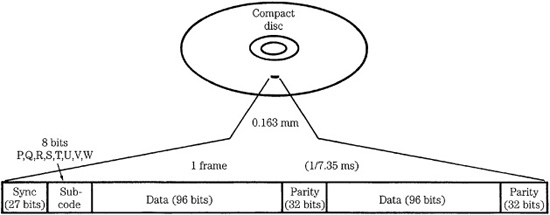
FIGURE 7.4 Elements of a CD frame shown without EFM modulation and interleaving. All data except the synchronization word undergo EFM modulation to create a total of 588 channel bits.
All data on a CD is formatted with frames. By definition, a frame is the smallest complete section of recognizable data on a disc. The frame provides a means to distinguish between audio data and its parity, the synchronization word and the subcode. Frame construction prior to EFM coding is shown in Fig. 7.4. All the required data is placed into the frame format during encoding. The end result of encoding and modulation is a series of frames, each frame consisting of 588 channel bits.
To begin assembly of a frame, six 32-bit PCM audio sampling periods (alternating between left and right channels) are grouped in a frame. This places 192 audio bits in the frame. The 32-bit sampling periods are divided to yield four 8-bit audio symbols. To scatter possible errors, the symbols from different frames are interleaved so that the audio signals in one frame originate from different frames. In addition, eight 8-bit parity symbols are generated per frame, four in the middle of the frame and four at the end. The interleaving and generation of parity bits constitute the error correction encoding based on the Cross-Interleave Reed–Solomon Code (CIRC). CIRC is discussed in Chap. 5.
One subcode symbol is added per frame; two of these subcode bits (P and Q) contain information detailing the total number of selections on the disc, their beginning and ending points, index points within a selection, and other information. Six of these subcode bits (R, S, T, U, V, and W) are available for other applications, such as encoding text or graphics information on audio CDs. After the audio, parity, and subcode data is assembled, this data is modulated using EFM. This gives the bitstream specific patterns of 1s and 0s, thus defining the lengths of pits and lands to facilitate optical reading of the disc. EFM permits a high number of channel bit transitions for arbitrary pit and land lengths. This increases data density and helps facilitate control of the spindle motor speed. To accomplish EFM, blocks of 8 data bits are translated into blocks of 14 channel bits using a dictionary that assigns an arbitrary and unambiguous word of 14 channel
bits to each 8-bit word. The 8-bit symbols require 28 = 256 unique patterns, and of the possible 214 = 16,384 patterns in the 14-bit system, 267 meet the pattern requirements; therefore, 256 are used and 11 discarded. A portion of the conversion table is shown in Table 7.1. EFM is discussed in Chap. 3.
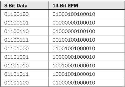

TABLE 7.1 Excerpt from the EFM conversion table. Data bits are translated into channel bits.
Blocks of 14 channel bits are linked by three merging bits. With the addition of merging bits, the ratio of bits before and after modulation is 8:17. The merging bits maintain the proper run length between words, suppress dc content, and aid clock synchronization. Successive EFM words cannot simply be concatenated; this might violate the run length of the code by placing binary 1s closer than 3 periods, or further than 11 periods. To prevent the former, a 0-merging bit is used, and the latter is prevented with a 1-merging bit. Two merging bits are sufficient to maintain proper run length. A third merging bit is used to more effectively control low-frequency content of the output signal. A 1 can be used to invert the signal and minimize accumulating dc offset in the signal’s polarity. This is monitored by the digital sum value (DSV); it tallies the number of 1s by adding a +1 to its count, and the number of 0s by adding a -1. The Red Book uses a simple one-symbol look-ahead strategy when choosing a DSV merging bit. An example of a merging bit determination, observing run length and DSV criteria, is shown in Fig. 7.5. Low-frequency content must be avoided because it can interfere with the operation of tracking and focusing servos that operate at low frequencies (below 20 kHz); in addition, low-frequency signals such as from fingerprints on the disc can be filtered out without affecting the data signal itself.
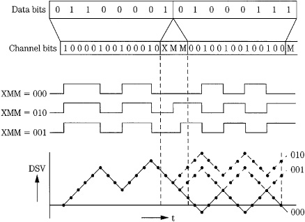
FIGURE 7.5 An example of merging-bit determination. With this data sequence, the first merging bit is set to 0 to satisfy EFM run-length rules; the two remaining bits are set to 00 to minimize DSV. (Heemskerk and Schouhamer Immink, 1982)
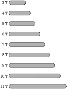
FIGURE 7.6 The complete collection of pit (and land) lengths created by EFM modulation ranges from 3T to 11T. Minimum pit length is 0.833 μm to 0.972 μm; maximum pit length is 3.054 μm to 3.56 μm, depending on velocity (1.2 m/s to 1.4 m/s).
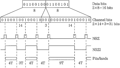
FIGURE 7.7 Each 8-bit half-sample undergoes EFM modulation, three merging bits concatenate 14-bit words, the NRZ representation is converted to NRZI, and transitions are represented as pit edges on the disc.
The channel stream produces pits and lands that are at least 2 but no more than 10 successive 0s long. The EFM pit/land family portrait is shown in Fig. 7.6. This collection of pit/land lengths encodes all user data contained on a CD. These pit/land lengths are described as 3T, 4T, 5T, …, 11T with T referring to the period of one channel bit. The signal is sometimes called the 3T-11T signal. Physically, pit and land lengths vary incrementally from 0.833 μm to 3.054 μm at a track velocity of 1.2 m/s, and from 0.972 μm to 3.56 μm at a velocity of 1.4 m/s.
The 3T-11T signal represents EFM channel bits on the CD surface. This is accomplished by coding the channel bits as nonreturn to zero (NRZ), and then as nonreturn to zero inverted (NRZI) data. Each logical transition in the NRZI stream represents a pit edge, as shown in Fig. 7.7. The code is invertible; pits and lands represent channel bits equally; inversions caused by merging bits do not affect the data content. When the signal is decoded, the merging bits are discarded. After EFM, there are more channel bits to accommodate, but acceptable pit and land patterns become available. With this modulation, the highest frequency in the signal is decreased; therefore, a lower track velocity can be utilized. One important benefit is conservation of disc real estate.
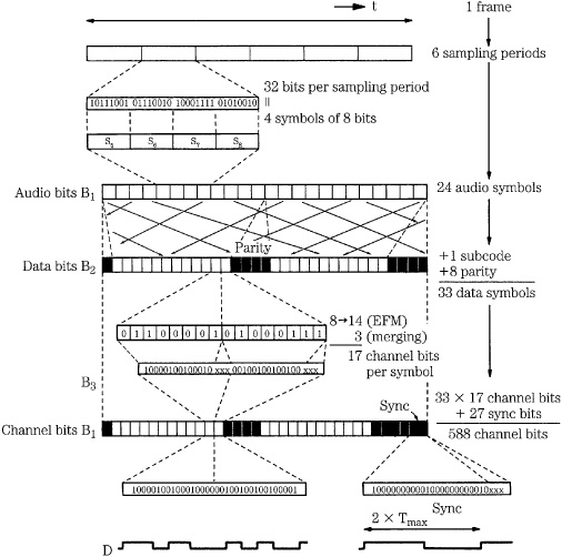
FIGURE 7.8 The algorithm used in the CD encoding process. Subcode and parity are added to the audio data, the data undergoes interleaving and modulation, and a synchronization word is added. (Heemskerk and Schouhamer Immink, 1982)
The resulting EFM data must be delineated, so a synchronization word is placed at the beginning of each frame. The synchronization word is uniquely identifiable from any other data configuration. Specifically, the 24 channel bit synchronization word is 100000000001000000000010 plus three merging bits. With the synchronization word, the player can identify the start of data frames. A complete frame contains one 24-bit synchronization word, 14 channel bits of subcode, 24 words of 14 channel bit audio data, eight words of 14 channel bit parity, and 102 merging bits, for a total of 588 channel bits per frame. Because each 588-bit frame contains twelve 16-bit audio samples, the result is 49 channel bits per audio sample. Thus when the data manipulation is completed, the original audio bit rate of 1.41 million bits per second is augmented to 4.3218 million channel bits per second. This resulting channel bitstream is physically stored on the disc. The entire encoding process is summarized in Fig. 7.8.
A finished CD must contain a lead-in area, program area, and a 90-second lead-out area of silence. The program area holds from 1 to 99 tracks. In addition, each track can contain up to 100 time markers called index points.
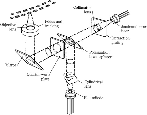
FIGURE 7.9 The optical elements in a three-beam laser pickup.
Player Optical Design
The function of a Compact Disc player is to recover the data encoded on discs. That task begins at the laser pickup used to read data. In addition, automatic optical tracking and focusing systems must be used. Players generally use either three-beam or one-beam pickup designs. We will consider the more common three-beam design first.
Optical Pickup
The data is recovered from a Compact Disc with an optical pickup, which moves across the surface of the rotating disc. A disc might contain 2 billion pits precisely arranged on a spiral track; the optical pickup must focus, track, and read that data track with submicron precision. The entire lens structure, laser source, and reader must be small enough to move laterally underneath the disc surface, moving in response to linear tracking information or user random access track programming. Although particulars vary among manufacturers, pickups are similar in design and operation. A three-beam optical pickup contains a laser diode, diffraction grating, polarization beam splitter, quarter-wave plate, and several lens systems, as shown in Fig. 7.9.
A semiconductor laser is used as the light source. Laser light is monochromatic; the optical system is designed for one wavelength and this minimizes chromatic aberrations. Laser light is coherent and can be focused to a small spot. It also yields a concise interference pattern, and can be manipulated via polarization. The laser beam originates from a laser diode. A CD pickup uses a semiconductor laser with approximately a 5-mW (milliwatt) optical output irradiating a coherent AlGaAs beam with a 780-nm wavelength to yield a spot power on the disc of about 0.5 mW. The light emitting properties of semiconductors have been utilized for many years. By adding forward bias to a PN junction, the injected part of the carrier is recombined to emit light; light-emitting diodes (LEDs) use this phenomenon. However, laser light is significantly different from ordinary light in that it comprises a single wavelength and is coherent with respect to phase. Thus, a modified device is required.
The injection laser diode used in CD players uses a double heterojunction structure. It contains a thin (perhaps 0.1 μm) active layer of GaAs semiconductor, sandwiched between heavily doped P- and N-type AlGaAs materials, sometimes called cladding layers. Forward bias creates a high concentration of electrons (from the N layer) and holes (from the P layer) in the active layer. An inverted population condition is created with many electrons in a high-energy state band and many holes in a low-energy band. Electrons fall to a lower energy band, releasing a photon; this reaches equilibrium with the input energy pumping rate. Stimulated light emission is thus induced. However, the light must be amplified, so several steps are taken. Both sides of the activating layer are sandwiched within materials with a large band gap to enclose the carrier, and the refraction ratio at both boundaries of the activating layer is different to provide enclosure. Also, for amplification within the layer, the crystal surface in the direction of the light emission is made reflective, and acts as a light resonator for continuous wave emission. A monitor photodiode is placed next to the laser diode to control power to the laser, compensating for temperature changes. The monitor diode conducts current proportionally to the laser’s light output. If the monitor diode’s current output is low with respect to a reference, current to the laser’s drive transistors is increased to increase the laser’s light output. Similarly, if the monitor current is too high, supply current to the laser is decreased to compensate. The laser diodes used in CD players have a very long life expectancy, from hundreds of thousands, to millions of operating hours.
In a three-beam pickup, the light from the laser point source passes through a diffraction grating. This is a screen with slits spaced only a few laser wavelengths apart. As the beam passes through the grating, it diffracts at different angles. When the resulting collection is again focused, it appears as a bright center beam with successively less intense beams on either side. In a three-beam pickup design, the center beam is used for reading data and focusing, and two secondary beams, the first-order beams, are used for tracking.
A polarization beam splitter (PBS) directs laser light to the disc surface, then angles the reflecting light to the photodiode. For incident light approaching the polarization beam splitter, it acts as a transparent window, but for reflected light with a rotated plane of polarization, it acts as a prism redirecting the beam. The PBS comprises two orthogonal prisms with a common face with a dielectric membrane between them. A collimator lens follows the PBS (in some designs it precedes it). Its purpose is to take the divergent light rays and make them parallel. The light then passes through a quarter-wave plate (QWP), a crystal material with anisotropic properties of double refraction. It rotates the plane of polarization of the incident and reflected laser light; plane of polarization is rotated 45° as light passes through the plate, and then rotates another 45° as reflected light returns through it. The reflected light is thus polarized in a plane at a right angle relative to that of the incident light, thus allowing the PBS to properly deflect the reflected light.
The final piece of optics in the light path to the disc is the objective lens with a numerical aperture of 0.45. It is used to focus the beam to about 1.0 μm (half-intensity level) at the reflective surface, somewhat wider than the pit width of 0.6 μm. The objective lens is attached to a two-axis actuator and servo system for up/down focusing motion and lateral tracking motion.
As noted, when the spot strikes a land interval between two pits, the light is almost totally reflected. When it strikes a pit (a bump from the reading side), a lower-intensity light is returned. Ultimately, a change in intensity is deciphered as a 1 and unchanged intensity as 0. The varying intensity light returns through the objective lens, the QWP (to further rotate plane of polarization), and the collimator lens, and strikes the angled surface of the PBS. The light is deflected and passes through a collective lens and cylindrical lens. These optics are used to direct the operation of the focusing servo system to keep the objective lens at the proper depth of focus. The beam’s main function, however, is to carry the data via reflected light to a four-quadrant photodiode. The electrical signals derived from that device are ultimately decoded into an audio waveform.
Autofocus Design
Nothing except laser light touches the data surface. That poses the engineering challenge of focusing on the pit surface and tracking the spiral pit sequence with nothing tangible to guide the pickup. To properly distinguish between pits and land, the laser beam must rely on interference in the reflected beam created by the height of the bumps, a 110-nm difference. The focus of the beam on the data surface is therefore critical; an unfocused condition might result in inaccurate or lost data. Specifically, the laser must stay focused within ±0.5 μm. A disc can contain deviations approaching ±0.4 mm. Thus, the objective lens must be able to refocus as the disc surface deviates. This is accomplished with a servo-driven autofocus system, which utilizes the center laser beam, a four-quadrant photodiode, control electronics, and a servo motor to move the objective lens. An operational diagram of the autofocus system is shown in Fig. 7.10.
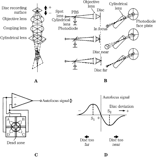
FIGURE 7.10 Astigmatism produced by a cylindrical lens is used to create a correction signal in an autofocus pickup. A. The main beam passes through a cylindrical lens; the image distorts and rotates relative to path length. B. Astigmatism creates an asymmetrical optical pattern because of path-length errors. C. A four-quadrant photodiode converts the optical pattern into an autofocus correction signal. D. The autofocus signal represents disc position and controls a servo to dynamically maintain focus.
Many methods have been devised to maintain focus on the pit track. In many pickups, the optical property of astigmatism is used to achieve autofocus. An astigmatic cylindrical lens has two different focal lengths and this performs the essential trick needed to detect an out-of-focus condition. As the distance between the objective lens and the reflective disc surface varies, the focal point of the system changes, and the image projected by the cylindrical lens changes shape. The change in the image on the photodiode is used to generate the focus correction signal.
When the disc surface lies at the focal point of the objective lens, the reflected image through the intermediate convex lens and the cylindrical lens is unaffected by the astigmatism of the cylindrical lens, and a circular spot strikes the center of the photodiode. When the distance between the disc and the objective lens decreases, the focal points of the objective lens, convex lens, and cylindrical lens move farther from the cylindrical lens, and the pattern becomes elliptical. Similarly, when the distance between the disc and the objective lens increases, the focal points are closer to the lens, and an elliptical pattern again results, but rotated 90° from the first elliptical pattern.
A four-quadrant photodiode reads an intensity level from each of the quadrants to generate four voltages. The value (A + B + C + D) creates an audio data signal. If a focus correction signal is mathematically created to be (A + C) - (B + D), the output error voltage is a bipolar S curve, centered around zero. Its value is zero when the beam is precisely focused on the disc; a positive-going focus correction signal is generated as the disc moves away, and a negative-going signal is generated as the disc moves closer. Using a closed-loop system, the difference signal continually corrects the mechanism to achieve a zero-difference signal, and hence a properly focused laser beam.
A servo system moves the objective lens up and down, to maintain a depth of focus within tolerance. A circuit deciphers the focus correction signal and generates a servo control voltage, which in turn controls the actuator to move the objective lens. The objective lens is displaced in the direction of its optical axis by a coil and a permanent magnet structure; it is similar to that used in a loudspeaker except that the objective lens takes the place of the speaker cone. A two-axis actuator incorporates these elements. The top assembly of the pickup is mounted on a base with a circular magnet ringing it. A circular yoke supports a bobbin with both the focus and tracking coils inside. Control voltages from the focus drive circuit are applied to the bobbin focus coil; this moves up and down with respect to the magnet. The objective lens thus maintains its proper depth of focus. The other axis of movement, from side to side, is used to maintain tracking.
Autotracking Design
An autotracking system is used to track the spiral pit sequence. The spiral pit track has a 1.6-μm pitch. An off-center disc might exhibit track eccentricity of over 100 μm. Vibration can further challenge the pickup’s ability to track within a ±0.1-μm tolerance. A laser beam system is appropriately used for tracking; any purely mechanical tracking system would be inordinately costly. Many different autotracking methods have been devised. In a three-beam pickup, a design that is widely used, the center beam is split by a diffraction grating to create a series of secondary beams of diminishing intensity. The first-order beams are conveyed to the disc surface along with the central beam. The central beam spot covers the pit track, while the two tracking beams are aligned above and below, and offset to either side of the center beam. During proper tracking, part of each tracking beam illuminates a pit, while the other part illuminates the land between pit tracks. The three beams are reflected back through the QWP and PBS; the main beam strikes the four-quadrant photodiode and the two tracking beams strike two separate photodiodes mounted to either side of the main photodiode. The complete photodiode assembly for data reading, tracking, and focusing is shown in Fig. 7.11.
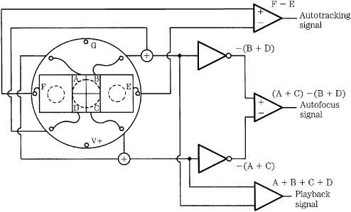
FIGURE 7.11 The four-quadrant photodiode (A, B, C, D) is used for autofocus and data playback. Photodiodes E and F are used for autotracking.
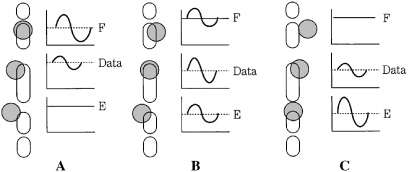
FIGURE 7.12 A tracking-correction signal is generated from an intensity imbalance in the two secondary beams. A servo system dynamically maintains tracking. A. Left mistracking (F < E). B. Correct tracking (F = E). C. Right mistracking (F > E).
If the three spots drift to either side of the pit track, the amount of light reflected from the tracking beams varies as one of the beams encounters more pit area; this results in less average light intensity. Meanwhile, the other beam encounters less pit area, returning greater reflected intensity. The relative voltage outputs from the two tracking photodiodes thus form a correction signal, as shown in Fig. 7.12. If tracking is precisely aligned, the difference between the tracking signals is zero. If the beams drift, a difference signal is generated, for example, varying positively for a left drift and negatively for a right drift, to create a tracking correction signal. That signal is applied to the two-axis actuator assembly containing the permanent magnet and focus/tracking coil. To correct for a tracking error, the correction voltage is applied to the coil; the bobbin swings around a shaft to laterally move the objective lens so that the main laser spot is again centered, and the tracking correction signal is again zeroed.
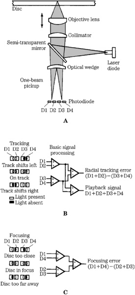
FIGURE 7.13 Design and operation of a one-beam optical pickup. A. The reflected beam is split by a wedge lens and directed to four photodiodes. B. Tracking is accomplished using intensity asymmetry in the beam. C. Focusing is maintained using the angle of deflection between the split beams.
One-Beam Pickup
The optical components of a one-beam pickup are shown in Fig. 7.13A, along with the photodiode array used to generate tracking and focusing signals, and read the data signal. A semi-transparent mirror is used to direct light from the laser diode to the disc surface. Light reflected from the disc passes through the mirror and is directed through a wedge lens. The wedge lens splits the beam into two beams, adjusted to strike an array of four horizontally arranged photodiodes. The outputs of all the photodiodes are summed to provide the data signal (D1 + D2 + D3 + D4), which is demodulated to yield both audio data and control signals for the laser servo system.
Autotracking uses a push-pull technique. A symmetrical beam is reflected when the laser spot is centered on the pit track. If the laser beam deviates from the pit track, interference creates intensity asymmetry in the beam. This results in an intensity difference between the split beams. If the beam is off track, one side of the beam encounters more pit area; hence, greater interference occurs on that side of the beam, and reflected light is less intense there, as shown in Fig. 7.13B. As a result, the split beam derived from that side of the beam is less intense, and the photodiode’s output is decreased. The difference between the pairs (D1 + D2) - (D3 + D4) is used to generate an error signal to correct the pickup’s tracking.
The intensity of the reflected beam could become asymmetrical from dirt in the optical system. This would create an offset in the tracking-correction signal, causing the pickup to remain slightly off track. To prevent this, a second tracking-error signal is generated. A low-frequency (for example, 600 Hz) signal is applied to the tracking servo. This signal modulates the output signal from the four photodiodes. If the pickup mistracks, a deviation occurs in the modulated signal. This signal is rectified and used to correct the primary tracking signal with a direct voltage. In this way, the effect of an offset is negated.
Autofocusing uses a Foucault technique. As shown in Fig. 7.13C, when correct focus is achieved, two images are centered between photodiode pairs. When focus varies, the focal point of the system is shifted. When the disc is too far, the split beams draw together; when the disc is too near, the beams move apart. The difference in intensity between diode pairs D1/D4 and D2/D3 forms a focus error signal (D1 + D4) - (D2 + D3) that maintains focus of the servo-driven objective lens.
Pickup Control
A motor must precisely move the pickup across the disc surface to track the entire pit spiral. The pickup must also be able to jump from one location on the disc to another, find the desired location on the spiral, and resume tracking. These functions are handled by separate circuits using control signals. Three-beam pickups are mounted on a sled that moves radially across the disc surface. Linear motors are used to position the pickup according to user commands, and bring the pickup within capture range of the autotracking circuit. Most one-beam pickups are mounted on a pivoting arm, which describes an arc across the disc surface. A coil and a magnet are placed around the pivot point of the arm. When the coil is energized, the pickup can be positioned anywhere across the pit track and its precise position corrected by the autotracking circuit. In both three- and one-beam designs, tracking in a CD player is similar to that of an analog LP record player. In the same way that a record groove pulls the stylus across an LP record, the autotracking system pulls the pickup across a CD, keeping the pickup on track.
For fast forward or reverse, a microprocessor assumes control of the tracking servo to provide faster motion than is possible during normal tracking. When the correct location is reached, the S curve generated by the tracking correction signal is referenced to a microprocessor-generated control signal, and a signal signifies that proper tracking alignment is imminent. Just prior to alignment, a brake pulse is generated to compensate for the inertia of the pickup. The actuator comes to rest on the correct track, and normal autotracking is resumed.
The reflectivity of discs can vary because of manufacturing process differences, soiling of the player optics, and so on. It is important to maintain a constant voltage level for proper data recovery; thus, the gain of the output control amplifier is variable, depending on the intensity of the reflected laser beam. This gain adjustment is automatically accomplished during the initial reading of the disc table of contents and is maintained while the disc is played. This occurs under control of a microprocessor. For example, the amplifier’s gain might be varied by ±10 dB. A control signal from the detection circuit can alert the focus servo system to defective or damaged discs. In severe cases, the objective lens is pulled away from the disc to prevent damage to the pickup.
Player Electrical Design
A CD player’s task of reproducing the audio signal requires demodulation and error-correction processing, as well as digital filtering and D/A conversion. Only then is the data recovered from the disc suitable for playback. In addition, controls and displays are required to interface the player with the human user. To simplify operation, and control the many subsystems, players incorporate one or more microprocessors in their design. A block diagram of a CD player is shown in Fig. 7.14.
EFM Demodulation
The voltage from the central photodiode array is output as an electrical data signal. This data signal resembles a sinusoid and is a radio-frequency (RF) signal. The RF signal represents the EFM code and thus contains the data stored on the disc. A collection of EFM waveforms is called the eye pattern, and is shown in Fig. 7.15. The eye pattern is always present whenever a player is tracking data, and the quality of the signal can be observed from the pattern. The RF signal is also used to maintain proper CLV-rotation velocity of the disc. The RF signal is first amplified, and applied to a phase-locked loop to establish the correct timebase and read a valid data signal. The data signal is encoded with EFM, which specifies that the signal be composed of not less than 2 or more than 10 successive 0s between 0/1 or 1/0 transitions. This results in nine different incremental pit lengths from 3 channel bits long to 11 channel bits long. The shortest pit/land length of 3T describes a 720-kHz signal and the longest length of 11T describes a 196-kHz signal (at 1.2 m/s). The large range of pit/land lengths, a range of nearly 400% of the smallest length, allows a substantial tolerance for jitter error (50 ns) during data playback.
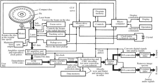
FIGURE 7.14 A CD player’s architecture, showing optical processing and output signal processing.
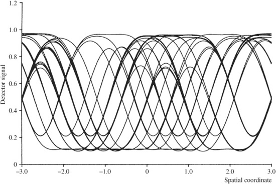
FIGURE 7.15 The modulated EFM data is read from the disc as an RF signal. The RF signal can be monitored through an eye pattern by simultaneously displaying successive waveform transitions. (Bouwhuis et al., 1985)
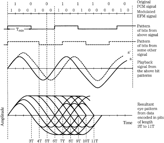
FIGURE 7.16 The RF signal contains all the audio and nonaudio data placed on the disc. The data is recovered by reading the EFM words in the eye pattern.
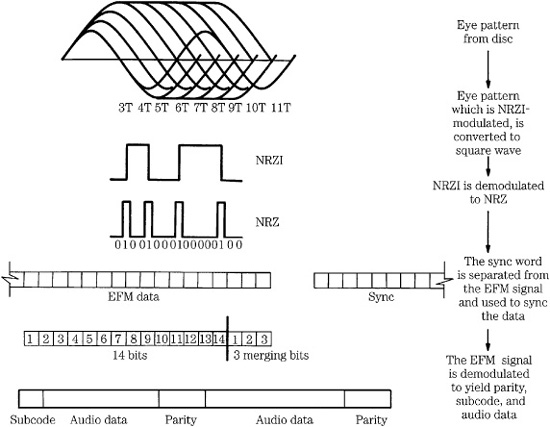
FIGURE 7.17 Demodulation of the EFM eye pattern signal permits recovery of synchronization, subcode, audio, and error-correction data.
The information contained in the eye pattern is shown in Fig. 7.16. Although this signal is comprised of sinusoids, it contains digital information. It undergoes processing to convert it into an NRZI signal, in which the preceding polarity is reversed whenever there is a binary 1. This does not affect the encoded data because the width of the EFM periods holds the pertinent values. The NRZI signal is further converted to NRZ.
Frame synchronization words that were added to each frame during encoding are extracted from the NRZ signal. They are used to synchronize the 33 symbols of channel data in each frame. Merging bits are discarded, and the individual channel bits are used to generate a synchronization pulse. The EFM code is demodulated so that every 14-bit EFM word is converted to 8 bits. Demodulation is accomplished by logic circuitry or a lookup table, using the recorded data to reference back to the original patterns of eight bits. The process from eye pattern to demodulated data is summarized in Fig. 7.17.
During decoding, data is applied to a buffer memory. Disc rotational irregularities might make data input irregular, but clocking ensures that the buffer output is precise. In addition, the buffer can also be used for data de-interleaving. To guarantee that the buffer neither overflows nor underflows, a synchronization control signal controls the disc rotation velocity. By varying the rate of data from the disc, the buffer level is properly maintained. Timebase correction is discussed in Chap. 4.
Error Detection and Correction
Following demodulation, data is sent to a Cross-Interleave Reed–Solomon Code (CIRC) algorithm for error detection and correction. Any error on a disc, for example, a 6T pit misinterpreted as a 7T pit, requires correction. The CIRC error correction decoding strategy uses a combination of two Reed–Solomon code decoders, C1 and C2. The CIRC is based on the use of parity bits and interleaving of the digital audio samples. Depending on implementation, CIRC can enable complete correction of burst errors up to 3874 bits (a 2.5-mm section of pit track). In practice, physical disc damage that would exceed the power of the error-correction algorithm usually causes laser mistracking anyway.
Theoretically, the raw bit-error rate (BER) on a CD is between 10-5 and 10-6; that is, there is one incorrect bit for every 105 (100,000) to 106 (1 million) bits on a disc. Following CIRC error correction, the BER is reduced to 10-10 or 10-11, or less than one bad bit in 10 billion to 100 billion bits. In practice, because of the high data density, even a mildly defective disc can exhibit a much higher BER. As discussed in Chap. 5, data is corrected through two CIRC decoders, C1 and C2. The C1 decoder corrects minor errors and flags uncorrectable errors. The C2 decoder corrects larger errors, aided by the error flags. Uncorrected errors leaving C2 are flagged as well. Error-correction flags generated from the CIRC algorithm during CD playback can represent the error rate (from sources such as poor pit geometry and uneven reflectivity) present on a disc.
If the CIRC decoder cannot correct all errors, it outputs the data symbols uncorrected (the parity symbols have been dropped), but marked with an erasure flag. Most of these symbols can be reconstructed with linear interpolation, using the combination of error flags to aid interpolation. The function of these error concealment circuits is to reduce such errors to inaudibility. Only uncorrected symbols, marked with erasure flags, are processed. All valid audio data passes through the concealment circuitry unaffected, except in the case of data surrounding a mute point, which is attenuated to minimize audibility of the mute. Concealment methods vary according to the degree of error encountered, and from player to player. In its simplest form, when a single sample is flagged between two correct samples, mean value interpolation is used to replace the erroneous sample. For longer consecutive errors, the last valid sample value is held, then the mean value is taken between the final held value and the next sample value. The system might permit recovery through adjacent sample interpolation of losses of up to 13,282 bits (8.7-mm track length).
If large numbers of adjacent samples are flagged, the concealment circuitry performs muting on one or more CD frames (1/75 second each). A number of previous valid samples (perhaps 30) are gradually attenuated with a cosine function to avoid the introduction of high-frequency components. Gain is kept at zero for the duration of the error, and then gain is gradually restored. Errors that escape the CIRC decoder without being flagged are not detected by the concealment circuitry, and therefore do not undergo concealment and may produce an audible click in the audio reproduction. Not all CD players are alike in error correction. Any CD player’s error correction ability is determined by the success of the strategy devised to decode the CIRC, as well as the concealment algorithm.
The AES28 standard describes a method to estimate the life expectancy of CDs (excluding recordable media) based on the effects of temperature and humidity. In AES28, block-error rate (BLER) is the measured response and the end-of-life criterion is a 10-second average of maximum BLER of 220. The ISO/IEC 10149 and ANSI/NAPM IT9.21-1996 standards also specify this error count.
Output Processing
Following error correction, the digital data is processed to recover subcode information. During encoding, eight bits of subcode information per frame are placed in the bit-stream. During decoding, subcode data from 98 frames is read and grouped together to form one block, then assigned eight different channels to provide control and (optionally) text or other information.
Output anti-imaging filtering is accomplished in the digital domain with oversampling filters. In oversampling, data is demultiplexed into left and right channels, and applied to an FIR transversal filter. Through interpolation, additional samples are inserted between disc samples, thus raising the sampling rate. An eight-times rate is common. As a result of oversampling, the output image spectra are raised to the corresponding multiple of the sampling frequency. When shifted to this higher frequency range, they can be easily removed by a low-order analog filter, free of phase distortion. Oversampling filters are discussed in Chap. 4. Following this processing, the data is converted into a format appropriate for the type of D/A converter used in the player. In most CD players, sigma-delta D/A converters are used, as described in Chap. 18.
Subcode
Each demodulated CD frame contains eight subcode bits, containing information describing where tracks begin and end, track numbers, disc timing, index points, and other parameters. The player uses the subcode bits to interpret the information on the disc, and facilitate user control of the player in accessing disc contents.
The eight subcode bits in every frame are designated as P, Q, R, S, T, U, V, and W as shown in Fig. 7.18A. Only the P and Q subcode bits are defined in the CD-Audio format. (There is no relation to the P and Q codes in CIRC.) A subcode block is constructed sequentially from 98 successive frames. Thus the eight subcode bits (P through W) are used as eight different channels, with each frame containing 1 P bit, 1 Q bit, and so on. This interleaving minimizes the effect of disc errors on subcode data. The subcode block rate can be determined: a CD codes 44,100 left and right 16-bit audio samples per second, so the 8-bit byte rate is 44,100 × 4, or 176.4 kbytes per second. With 24 audio symbols in every frame, the frame rate is 176.4/24 or 7350 Hz. Because 98 frames form one subcode block, the subcode block rate is 7350/98 or 75 Hz; that is, 75 subcode blocks per second. Parenthetically, 7350 frames per second multiplied by the number of channel bits, 588, results in 4.3218 MHz, the overall channel bit rate.
A subcode block is complete with its own synchronization word, instruction, data, commands, and parity. The start of each subcode block is denoted by the presence of S0 and S1 synchronization bits in the first symbol positions of two successive blocks. On most audio discs, only the P and Q subcode channels contain information; the others are recorded with 0s.
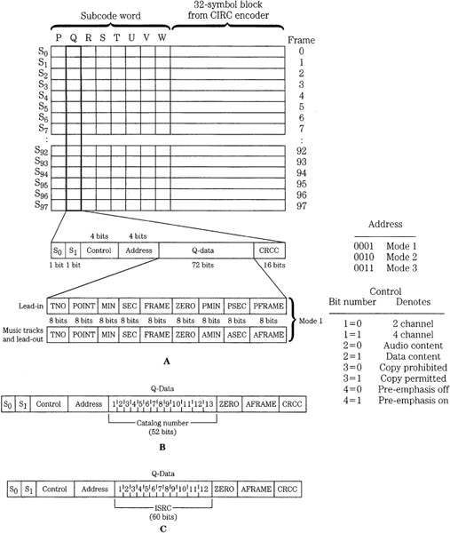
FIGURE 7.18 The data structure of the CD subcode block, showing detail of the Q subcode channel. A. Mode 1 has provisions for a lead-in and program format. B. Mode 2 format stores UPC codes. C. Mode 3 format stores ISRC code.
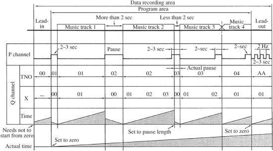
FIGURE 7.19 An example of the program information contained in the P and Q subcode channels across a disc surface.
The P channel contains a flag bit. It designates the start of a track, as well as the lead-in and lead-out areas on a disc, as shown in Fig. 7.19. The music data is denoted by 0, and the start flag as 1. The length of a start flag is a minimum of 2 seconds, but equals the pause length between two tracks if this length exceeds 2 seconds. Lead-in and lead-out signals tell the player where the music program on the disc begins and ends. A lead-in signal consists of all 0s appearing just prior to the beginning of the music data. At the end of the lead-in, a start flag that is 2- to 3-seconds long appears just prior to the start of music. During the last music track, preceding the lead-out, a start flag of 2 to 3 seconds appears. The end of that flag designates the start of the lead-out and the flag remains at 0 for 2 to 3 seconds. Following that time, a signal consisting of alternating 1s and 0s (at a 2-Hz rate) appears. These signals could be used by players of basic design to control the optical pickup. For example, a player could count start flags placed in the blank interval between tracks to locate any particular track on a disc. In practice, players use only the more sophisticated Q code.
The Q channel (see Fig. 7.18) contains four basic kinds of information: control, address, Q data, and an error detection code. The control information (four bits) handles several player functions. The number of audio channels (2 or 4) is indicated; this distinguishes between two- and four-channel CD recordings (the latter was never implemented). The digital copy (permit/deny) bit regulates the ability of other digital recorders to record the CD’s data digitally. Pre-emphasis (on/off) is also coded. When indicated, the player reads the code and switches to the de-emphasis circuit.
The address information consists of four bits designating the three modes for the Q data bits. Primarily, Mode 1 contains number and start times of tracks, Mode 2 contains a catalog number, and Mode 3 contains the International Standard Recording Code (ISRC). Each subcode block contains 72 bits of Q data, as described below, 16 bits for the cyclic redundancy check code (CRCC) generation polynomial x16 + x12 + x5 + 1, used for error detection on the control, address, and Q data information in each block.
As noted, there are three modes of Q data. Mode 1 stores information in the disc lead-in area, program area, and lead-out area. The data content in the lead-in area (see Fig. 7.18A) differs from that in the other areas. Mode 1 lead-in information is contained in the table of contents (TOC). The TOC stores data indicating the number of music selections (up to 99) as a track number (TNO) and the starting times (P times) of the tracks. The TOC is read during disc initialization, before audio playback begins, so that the player can respond to any programming or program searching that is requested by the user. In addition, most players display this information.
In the lead-in area, the TNO is set to 00, indicating that the data is part of a TOC. The TOC is assembled from the point field; it designates a track number and the absolute starting time of that point in minutes, seconds, and frames (75 frames per second). The times of a multiple disc set can also be designated in the point field. When the point field is set to A0 (instead of a track number) the minute field shows the number of the first track on the disc. When the point field is set to A1, the minute field shows the number of the last track on the disc. When set to A2, the absolute running time of the start of the lead-out track is designated. During lead in, running time is counted in minutes, seconds, and frames. The TOC is repeated continuously in the lead-in area, and the point data is repeated in three successive subcode blocks.
In the program and lead-out area (see Fig. 7.18A) Mode 1 contains track numbers, index numbers (X) within a track, time within a track, and absolute time (A-time). TNO designates individual tracks and is set to AA during lead-out. Running time is set to zero at the beginning of each track (including lead-in and lead-out areas) and increases to the end of the track. Starting at the beginning of a pause, time counts down, ending with zero at the end of the pause. The absolute time is set to zero at the beginning of the program area (the start of the first music track) and increases to the start of the lead-out area. Program time and absolute time are expressed in minutes, seconds, and frames. Index numbers both separate and subdivide tracks. When set to 00, X designates a pause between tracks, and countdown occurs. Nonzero X values set index points inside tracks. A 01 value designates a lead-out area. Using indexing, up to 100 locations within tracks can be indexed. Index 0 marks the onset of the pre-gap (pause) that precedes the audio portion of the track and index 1 marks the beginning of the audio portion. The pre-gap is nominally 2 seconds long. Mode 1 information occupies at least 9 out of 10 successive subcode blocks. (Fig. 7.19 summarizes the timing relationships contained in Mode 1 Q channel information.)
In Q data Modes 2 and 3 (see Figs. 9.18B and C) the program and time information is replaced by other kinds of data. Mode 2 contains a catalog number of the disc, such as the UPC/EAN (Universal Product Code/European Article Number) codes. The UPC/EAN code is unchanged for an entire disc. Mode 2 also continues absolute time count from adjacent blocks. Mode 3 provides an ISRC number for each track. The ISRC number includes the country code, owner code, year of recording, and serial number. The ISRC code can change for each track. Mode 3 also continues absolute time.
Modes 2 and 3 can be omitted from the subcode if they are not required. If they are used, Mode 2 and Mode 3 must occupy at least one out of 100 successive subcode blocks, with identical contents in each block. In addition, Mode 2 and 3 data can be present only in the program area. The remaining six subcode bits (R, S, T, U, V, and W) are packed with zeros on most CDs. However, they are available for CD + G/M or CD Text data as described below.
Unlike newer formats such as DVD and Blu-ray, the CD was not originally designed to hold extensive text or menu information. Thus, the CD Text feature was appended to the original Red Book specification in June 1996. CD Text allows the album title, song titles, artist, composer, producer, and other text information to be added to a disc at the time of manufacture. Compatible players can use CD Text to display this textual information and also to search for particular album titles. CD Text data is placed in the subcode R-W subchannels; it supports a color display of 21 lines of 40 characters each and the option of displaying bitmaps and JPEG pictures. It also permits levels of menus, as well as scrolling lyrics. CD Text was envisioned for numerous applications. For example, catalog number, song title, and artist name can be automatically broadcast via an FM subcode data service. Also, record companies could mark highlighted disc areas for playback at record store listening kiosks. In practice, CD Text is used to display basic album text information.
Other unique approaches can be used to access text information. For example, when using a compatible software CD player, the database at www.cddb.com can be accessed to create metadata files with title, artist, and timing information. When a new disc is loaded, the specific information is accessed over the Internet and then stored locally for subsequent use each time the disc is played. The system creates a unique identifier for every title, based on its running times and number of tracks.
Disc Manufacturing
The Compact Disc manufacturing process enjoys the advantages of the disc medium, in which the information is placed on the disc simultaneously with its creation. However, the CD requires sophisticated manufacturing processes and stringent quality control to guarantee a satisfactory yield. Although manufacturers use different techniques to produce CDs, the manufacturing process always involves three general steps: premastering, disc mastering, and disc replication. Premastering can be accomplished in a recording studio or even on a personal computer. However, disc mastering and replication require specialized equipment found only in disc manufacturing plants. DVD and Blu-ray disc manufacturing is similar to CD manufacturing. The principal difference is the dual-substrate construction of DVD discs, and the presence of additional data layers in some DVD and Blu-ray discs. These differences are discussed in Chaps. 8 and 9. SACD discs are manufactured similarly to DVD discs.
Premastering
Premastering is the culmination of the recording process and the prelude to disc mastering and replication. In premastering, an audio media is prepared prior to creating a glass master disc. This media contains the final, edited version of the content to be replicated. This version should be recorded at the highest resolution possible, on a media suitable for robust storage. A variety of media are used to hold these recordings. Originally, most audio CDs were manufactured from data on 3/4-in U-Matic videotape cassettes; as noted, this accounts for the selection of 44.1 kHz as the CD sampling frequency. Data was formatted using a digital audio processor such as the PCM-1630 recording to a videocassette recorder. The videocassette contained the following information: video format tracks with digital audio data; analog audio channel 1 with PQ subcode; and analog audio channel 2 with continuous SMPTE (nondrop frame) timecode.
In many cases, Exabyte data tapes are used to hold the audio recording. Exabyte tapes use specially formulated 8-mm Hi-8 videotape and are also used to archive computer data. Exabyte is attractive because glass masters may be created at faster than real time speeds. In other cases, audio data is held on a hard-disk drive or is delivered by the Internet or other network protocols. For audio content, the Disk Description Protocol (DDP) file format is employed to hold an image file of Red Book data and PQ subcode information. Both DDP 1.0 and DDP 2.0 are used; the 2.0 specification writes the table of contents to the end of the tape. Generally, it is recommended to supply a replication plant with an Exabyte 8-mm tape with DDP files (including PQ and ISRC data) that has been verified by the artist and producer. In some cases, audio data is written to CD-ROM disc as 24-bit WAV or AIFF files. On request, a test disc can be sent to the artist and producer.
DAT tapes and CD-R discs can be used to deliver audio content to a replication facility, but their relatively higher error rates and susceptibility to damage make them less than ideal. If they are used, finished media must be checked to ascertain the error count. An analog tape can be used, but it must be converted to an interim digital format. In some cases, the digital source media may not be compatible with the mastering equipment; for example, the sampling frequencies may differ. Although the digital recording could be converted to analog and then to a compatible format, degradation would result; hence, a sampling frequency converter should be used for a digital-to-digital transfer without significant deterioration in signal quality.
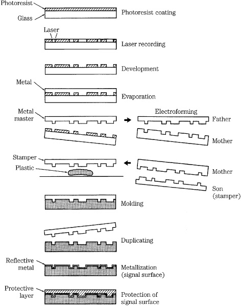
FIGURE 7.20 A summary of the principal steps in the CD disc manufacturing process.
In many cases, no matter what media resource is used, data is converted to a DDP file with the necessary PQ and ISRC codes and stored on Exabyte 8-mm tape or a hard-disk drive. Care must be taken to ensure that equipment uses a stable central clock, and that the signal path is free of defects. From there, data passes to the laser beam recorder (LBR) for disc mastering.
Disc Mastering
Compact Disc mastering is the first process in disc manufacturing; the entire process is shown in Fig. 7.20. In many cases, a photoresist process is used to create a master disc, employing techniques similar to the microlithography used to manufacture integrated circuits. A glass plate about 240 mm in diameter and 6 mm thick, composed of simple float glass, is washed in alkali and freon, lapped, and polished with a CeO2 optical polisher. The plate is prepared in a clean room with extremely stringent dust filtering. After inspection and cleaning, the plate is tested for optical dropouts with a laser; any burst dropouts in reflected intensity are cause for rejection of the plate. To prepare the plate for photoresist mastering, an adhesive is applied, followed by a coat of photoresist applied by spin coating. The depth of the photoresist coating is critical because it determines the ultimate pit depth. The plate is cured in an oven and stored, with a shelf life of several weeks. The plate is ready for mastering.
The laser beam recorder is a device that photographically exposes the data spiral into the photoresist on the master glass disc. The LBR may have a control rack consisting of a computer, tape transport, hard-disk drive, CD and subcode encoders, and diagnostic equipment. The recorder may use an HeCd or argon ion gas laser, at 442 nm and 458 nm, or 488 nm, respectively, with a numerical aperture (NA) of 0.9. The laser is intensity-modulated by an acousto-optical modulator to create the exposing signal corresponding to the encoded data. Another laser, which does not affect the master disc photoresist, is used for focusing and tracking. The master glass plate coated with photoresist is placed on the LBR and exposed with the laser to create the spiral track, creating the disc contents as the audio signal is played and CD-encoded. During disc mastering, the PQ subcode is uniquely created for the glass master using a subcode editor, and is modulated into the CD bitstream.
Quality of the production discs depends directly on the LBR’s signal characteristics such as eye pattern symmetry, signal modulation amplitude, and track following. The length, width, and edge angle of the pits on the replicated discs are subject to the exposure intensity and developing time of the photoresist. To guard against disc contamination, stringent air filtering is used inside the LBR. Although the optics are similar to those found inside consumer CD players (laser source, polarization beam splitter, objective lens), the mechanisms are built on a grander scale, especially for isolation from vibration. For example, the stylus block may be supported and moved by an air-float slider. The entire mastering process is accomplished automatically, under computer control.
After exposure in the laser beam recorder, the glass master is developed by an automatic developing machine. Developing fluid washes the rotating disc surface, removing the exposed areas of photoresist, leaving pits in the photoresist. During development, a laser monitors photoresist depth and stops development when the proper engraving depth has been reached; the developing pits form a diffraction grating, reflecting multiple beams. The relative intensity of the beams is monitored to indicate pit geometry. As noted, compromises must be made to determine the optimum practical pit depth. A production pit depth of 0.11 μm to 0.13 μm is typical. Following etching, a metal coating, usually of silver, is evaporated onto the photoresist layer. The master glass plate is ready for electroforming.
In some cases, a nonphotoresist (or “direct-effect”) mastering technique is used. Using a glass plate coated with a dye-polymer recording layer, the LBR directs the input signal to an acousto-optical modulator that controls the recording laser. Pits are physically cut directly into the recording layer on the master disc using a blue laser. The system provides a direct-read-after-write (DRAW) function so that the recorded signal can be continuously monitored during mastering. A trailing red laser is focused on the disc just behind the recording laser, but does not affect the recording. Instead, it reads data so that analysis equipment can dynamically control cutting laser power and other critical parameters to ensure optimum pit geometry and decode the EFM signal to evaluate data error rates; this decreases production time.
Electroforming
The metallized master disc is transferred to an electroplating room where the plating process produces metal stampers. First, evaporation is used to coat the master disc with a silver or electroless nickel layer to make it electrically conductive. The master electroplating process imparts a nickel coating on the metallized glass master. The metal part is separated from the glass master, and any photoresist is removed. This metal disc is called the metal master, or father. Using the same electroplating process, the resulting metal father is used to generate a number of positive nickel impressions, called mothers. The process is repeated to produce a number of negative impression stampers, or sons. Disc substrates are replicated from these stampers. A center hole is precisely punched into the stamper. Stampers are about 300 μm thick—a thick metal foil. Perhaps 30,000 discs may be made from a stamper before wear limits its use.
Disc Replication
Mass production of discs can be accomplished with injection molding to produce disc substrates. A polycarbonate material is used. It is rugged, is one of the most stable of polymeric plastics, and in particular has a low vapor absorption coefficient that is about 70% less than that of polymethyl methacrylate (PMMA) plastic, also known as Plexi-glass. Polycarbonate material has an inferior birefringence specification, especially when produced by injection molding; however, injection molding is a more efficient production method. After experimentation with different kinds of mold shapes and molding conditions, techniques for producing a single piece polycarbonate substrate were achieved. CD birefringence is specified to be less than 100 nm (measured double pass through the substrate). Polycarbonate pellets are heated to about 300°C; molten polycarbonate is injected into the mold cavity, faced on one side by the metal stamper, and the disc substrate (with pits) is produced; water channels in the molds help cool the substrate in less than 5 seconds. The substrate center hole is formed simultaneously.
After molding, a metal layer (about 50 nm to 100 nm thick) is placed over the pit surface to provide reflectivity. In most cases, aluminum is used; however, silver or gold or another metal can be used. The reflection coefficient of this layer, including the polycarbonate substrate (note that the CD player laser must pass through the substrate to the metal layer), is specified to be at least 70%. Aluminum evaporation can be accomplished with vapor deposition in a vacuum chamber. Alternatively, high-voltage magnetron sputtering can be used to deposit the reflective layer. A cold solid target is bombarded with ions, releasing metal molecules that coat the disc. Using high voltages, a discharge is formed between a cathode target and an anode. Permanent magnets behind the cathode form a concentrated plasma discharge above the target area. Argon ions are extracted from the plasma; these ions bombard the target surface, thus sputtering it; the disc is placed opposite the target and outside the plasma region. Metallization may take 3 seconds. The metal layer is covered by an acrylic plastic layer with a spin-coating machine, and cured with an ultraviolet light. This layer protects the metal layer from scratches and oxidation. The label is printed directly upon this layer.
The final step in CD manufacturing is inspection and packaging. Finished discs are inspected for continuous and random defects, using automated checking. Discs can be scanned to check for physical defects such as inclusions or bubbles in the substrate, missing metallization and staining, to evaluate the replication process. Scanners can use laser light, regular light, and cameras to quickly check discs. Because no data is read, scanning is fast and thus is often incorporated in the production line to check every disc. Disc readers check error rates, tracking, jitter, and data signal levels. This is more time-consuming and is typically done off-line on selected discs. Other off-line tests can check thickness variation, dynamic balance, and other parameters.
A number of optical, mechanical, and electrical criteria have been established. Molded discs are checked for correct dimensions, lack of flash and burrs, birefringence, reflectivity, flatness (skew angle), and general appearance. The pit surface is checked for correct pit depth, correct pit volume, and pit form and dimensions. The metallized coating is checked for pinholes and uneven thickness, and uneven or incorrect reflectivity. Birefringence can be checked with a circularly polarized light used to convert the phase change to an intensity variation measured with a photodiode.
Angle deviation measures the angle formed by the normal to the disc in the radial direction. This angle is critical because any deviation causes the reflected laser beam to deviate from its return path through the objective lens. This angle deviation could result from an improper manufacturing method; specifications call for a maximum angle of ±0.6°. Disc eccentricity measures the deviation from circularity of the pit track and the positioning of the center hole. Eccentricity may result if the stamper is not punched correctly or if the stamper is not precisely centered in the injection mold. Also, the electroforming or molding processes introduce some eccentricity in the shape of the pit track. In addition, the player’s positioning of the disc in the drive might introduce eccentricity. If it is excessive, it could exceed the ability of the radial tracking servo of the player. Tolerances for deviation from circularity call for maximum eccentricity of ±70 μm. Disc eccentricity must also account for alignment of the center hole. Specifications call for a center hole tolerance of 0.1 mm. A hole that is off-center can lead to disc imbalance, and noise and resonance errors. Push-pull tracking evaluates the intensity of light returning from the left and right sides of the pit track; it can be used to monitor pit geometry, which affects the overall gain of the tracking servo.
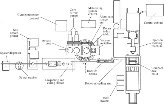
FIGURE 7.21 An example of the in-line hardware used to manufacture Compact Discs. Critical processes are enclosed in small clean enclosures.
Disc quality can be evaluated by examining the analog RF 3T-11T signal output from a pickup. The I11 signal is derived from reading an 11T pit/land and an I3 signal is derived from a 3T pit/land. ITOP measures the distance from the signal’s baseline to the top of the amplitude of an I11 signal. The I3/ITOP ratio must be between 0.3 and 0.7, and the I11/ITOP ratio must be greater than 0.6. The higher the value, the better the signal’s condition. Radial noise measures how much a pickup moves side to side to maintain tracking, and thus evaluates the straightness of a pit track. The maximum value is 30, and lower figures are better. Push-pull magnitude measures the magnitude of the tracking signal, which is determined by pit depth. Shallow pits yield a high push-pull magnitude, and deep pits yield a low push-pull. The minimum value for push-pull is 0.04 and the maximum value is 0.09. Crosstalk measures the interference from adjacent pit tracks; it increases as the track pitch is reduced. The maximum value for crosstalk is specified at 50%. Jitter measurements can monitor pit accuracy; maximum peak-to-peak jitter should be less than 50 ns (for modulation frequency of the channel bit clock frequency greater than 4 kHz).
Following packaging and wrapping, discs are ready for distribution. In most cases, the injection machine, sputtering machine, spin coater, and label printer are consolidated into one production unit; it might take a disc 2 minutes to travel from the injection machine to labeling; one unit can produce 2 million discs per year. Equipment used for disc replication is shown in Fig. 7.21.
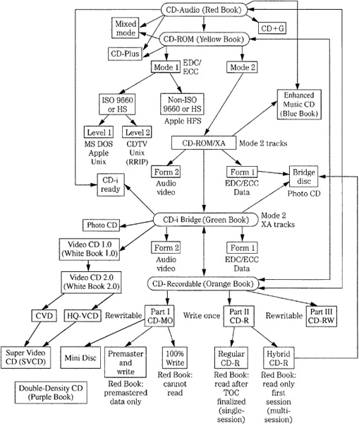
FIGURE 7.22 A simplified road map showing the complex interrelationships between CD formats.
Alternative CD Formats
The Compact Disc is an efficient storage medium allowing user information to be reliably stored on a low-cost disc using CIRC error correction and EFM coding techniques. Fortuitously, that medium is available for other storage applications beyond the CD-Audio format (also called CD-DA or CD-Digital Audio). Computer software, published material, or audio and video files can be stored in the CD-ROM file format. The CD-R standard specifies a write-once disc format, and the CD-RW standard describes a fully erasable disc format. As with many families, the interrelationships between members of the CD family are somewhat complicated, as shown in Fig. 7.22. Complications and incompatibilities arose because the CD was originally conceived only as a music carrier; subsequent evolutions occurred in a piecemeal fashion. In contrast, newer formats such as DVD and Blu-ray disc were initially designed for multiple uses. Despite their drawbacks, these alternative CD formats greatly expand the range of applications open to the CD.
CD-ROM
The Compact Disc Read-Only Memory (CD-ROM) format extends the digital audio CD format to the broader application of information storage in general. Rather than store only music, the CD-ROM format is used for diverse data. The CD-ROM format forms the basis for a read-only electronic publishing medium applicable to computer applications and for information distribution such as book publishing, dictionaries, technical manuals, business catalogs, and so on. Its advent represented an entirely new technology of information dissemination. CD-ROM discs use the same disc construction as audio discs, and can be mass produced with the same replication equipment; however, more stringent quality control may be required.
The CD-ROM standard is derived from the CD-Audio standard, but specifically defines a file format for general data storage. Unlike CD-Audio, CD-ROM is not tied to any specific application. Both standards use the 120-mm-diameter disc, but with different data formats. The CD-ROM standard, sometimes called the Yellow Book, was issued in 1983. In 1989, it was also specified in the ISO/IEC 10149 (ECMA-130) standard (International Organization for Standardization/International Electrotechnical Commission).
A Mode 1 CD-ROM disc nominally holds 682 million bytes of user information (333,000 blocks × 2048 bytes). This storage area is roughly equivalent to 275,000 pages of alphanumerics. The CD-ROM format can store information such as computer applications software, audio files such as WAV or MP3, video files, operating systems, online databases, published reference materials, directories, encyclopedias, libraries of still pictures, parts catalogs, or other types of information. Read-only CD-ROM discs form a publishing medium that is much more efficient than paper. For example, the U.S. Navy investigated the use of CD-ROM to reduce the paperwork on naval ships. They found that a cruiser carries about 5.32 million pages of documentation, weighing almost 36 tons. That mass of paperwork could be reduced to about 20 CD-ROM discs, weighing 280 grams. On the other hand, the CD-ROM is not ideal for computer applications. The file sizes are not an exact power of 2 as computers prefer, interleaving dictates that large amounts of data must be read to recover any useful information, CLV rotation requires motor speed changes as data is accessed across the disc radius, and CD-ROM is not erasable. However, the CD-ROM data format is widely used to write data to CD-R and CD-RW discs.
The CD-ROM standard uses a data format modified from the CD-Audio standard. Ninety-eight CD frames are summed (as in CD subcode) to form a data block of 2352 bytes (24 byte × 98 frames) in length. A disc is divided into a maximum of 330,000 blocks; a 60-minute disc holds 283,500 blocks. The first 12 bytes of a block form a synchronization pattern, and the next 4 bytes comprise a header field for time and address flags. The remaining 2336 bytes can store user data, or data plus extended error correction, depending on the mode selected. The header contains three address bytes and a mode byte. Addresses are stored as a disc playing time. One address byte stores minutes, the second byte stores seconds, and the third stores block numbers within the second. For example, an address of 62-13-08 identifies the 8th block in the 13th second of the 62nd minute on the disc.
The mode byte identifies three modes, used for two different types of data. There are two data modes, as shown in Fig. 7.23. The Mode 1 format assigns 2048 bytes of each block to user data. Each block contains 2 kbytes (2 × 1024) of user data; 280 bytes are given to extended error detection and correction (EDC/ECC), which is an extra layer of coding in addition to the basic Red Book CIRC code. The Mode 2 format allows for the full 2336 bytes to be used for user data (14% more data), but in practice is rarely used except when coded in CD-ROM/XA mode (described below). There is also a null mode, Mode 0. In all cases, after sector data is created, the CD-ROM bitstream is applied to conventional CD encoding such that CIRC and EFM, and other processing is applied just as in an audio CD. For example, Mode 1 data thus has two independent layers of error correction (EDC + ECC and CIRC) whereas Mode 2 uses only CIRC coding.
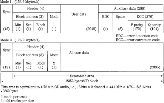
FIGURE 7.23 The CD-ROM specification contains two modes of data block structures. Mode 1 allows for extended error detection and correction, and Mode 2 provides capacity for additional user data.
Because of its extended error correction, Mode 1 has the greatest applications. The EDC/ECC field is essential for high-density numerical data storage, which is more demanding than audio data. A GF(28) Reed–Solomon Product Code (RS-PC) is used to encode each block. It produces P and Q parity bytes with (26,24) and (45,43) codewords, respectively. Because the EDC/ECC field is independent and supplements the CIRC error correction code applied to the frame structure, the error rate is improved over that of CD-Audio. In Mode 1, the typical CD-ROM bit-error rate is approximately 10-15, one uncorrectable bit in every 1015bits.
CD-ROM/XA (eXtended Architecture) is an extension to the Yellow Book Mode 2 standard and defines a new type of data track; computer data, compressed audio data, and video and picture data can all be contained on one XA track. CD-ROM/XA Mode 2 differs from CD-ROM Mode 2 because it provides a subheader that defines the block type, as shown in Fig. 7.24. In this way, the XA track can interleave Form 1 and Form 2 blocks; this is useful in some applications. Specifically, XA defines two types of blocks: Form 1 for computer data and Form 2 for compressed audio/video data. The former provides a 2048-byte user area, and the latter provides 2324 bytes. CD-Audio data cannot be placed on an XA track. The XA data rate is 1.4 Mbps. Clearly, special processing is needed to decode the various data types found on an XA disc. Some players are dedicated to specific types of CD-ROM/XA discs; the Video CD and Photo CD are types of CD-ROM/XA. The CD-ROM/XA format is defined in the White Book. Not all CD-ROM drives support CD-ROM/XA; in some cases a special interface board must be used.
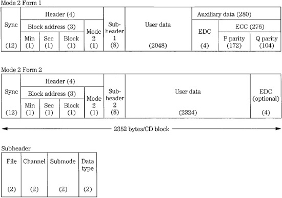
FIGURE 7.24 The CD-ROM/XA data format is based on the CD-ROM Mode 2 format. It provides two forms: extended error detection and correction, and increased user data capacity.
Hybrid audio/data CD formats, sometimes called CD Extra (formerly CD Plus), Enhanced CD, and Stamped Multisession or Mixed Mode, combine several different format types (such as CD-Audio and CD-ROM/XA) on a single disc. For example, a CD Extra disc has Red Book audio data in the first session, with Yellow Book ROM/XA Mode 2, Form 1 format in the second session. Each individual session must use the same data type. A CD-Audio player plays the first session, but will not play the second. A CD-ROM drive reads both the audio and nonaudio sessions, the latter containing, for example, programming relating to the audio session. For PC and Macintosh compatibilities, a hybrid disc would contain both ISO 9660 and HFS directories with common files such as video that can be shared between platforms.
An Enhanced CD disc is essentially a replicated multisession Orange Book disc, in which each session has lead-in and lead-out areas. CD Extra discs must contain the AUTORUN.INF file to start the multimedia application, as well as CDPLUS and PICTURES folders. The former contains album title, artist, record company, catalog number, track titles with pointers to lyrics, and MIDI files. The latter contains a JPEG file of the album cover, and other files. CD Extra is described in the Blue Book (issued in 1995).
Alternatively, in Mixed Mode CDs, ROM data is placed in Track 1, while CD-Audio data is placed in subsequent tracks. However, with this design, an audio player may access the ROM track and erroneously output noise rather than muting. To avoid this, a “pre-gap” technique may be used such that ROM data is “hidden” by placing it after the disc TOC, but before the Red Book first track (containing music). ROM data (up to 40 minutes of equivalent playing time) is placed between Index 0 and Index 1 of Track 1, while the music starts at Track 1, Index 1. An audio player thus skips over the data, starting playback at the first music track. However, the pre-gap area is not accessible to all PC software. The track layout of the Red Book CD and several alternative CD types are summarized in Fig. 7.25.
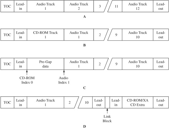
FIGURE 7.25 Several alternate CD types have been developed to allow both audio and nonaudio data to be placed in CD tracks. A. Red Book. B. Mixed Mode. C. Pre-gap. D. CD Extra.
As noted, the CD-ROM data format is similar to that of music CDs; music discs can be played on ROM players, but ROM discs are not playable on audio players. A CD-ROM drive typically includes D/A conversion and audio output stages, but requires an interface and an external computer for nonaudio data output. In most designs, the consolidation of both functions into one player is ideally cost effective. To permit this, a CD-ROM disc automatically identifies itself as differing from an audio CD (through the Q subcode channel).
Unlike the CD-Audio standard, the CD-ROM standard does not stipulate how data is to be defined. In an effort to provide compatibility, the ad hoc High Sierra group (meeting at Del Webb’s High Sierra Hotel and Casino) developed a standard logical file structure; the High Sierra standard was issued in 1985. It was adopted with minor revisions by the ISO as standard ISO 9660 (ECMA-119), “Volume and File Structure of CD-ROM for Information Exchange.” It universally specifies how computer data is placed on a CD-ROM disc; to read the data, the computer operating system must be capable of reading the ISO 9660 file structure. Level One 9660 requires that files be written as a continuous stream with file name restrictions similar to the MS-DOS file system. Level Two allows longer file names, and is not usable in MS-DOS systems. Level Three is open-ended. MSCDEX.EXE is an MS-DOS Extension available from Microsoft; it contains extension programming and drivers so that an MS-DOS program can access a CD-ROM. The computer requires both Microsoft Extensions and the device driver for the MPC ROM drive. MSCDEX.EXE is often placed in the AUTOEXEC.BAT file, and the device driver is loaded from CONFIG.SYS. The computer can then read 9660 file directories and files from the disc.
Using extensions to ISO 9660, directories and files can be accessed from diverse platforms. The extension of ISO 9660 for the Unix platform is sometimes called the Rock Ridge extension; this is incorporated in the IEEE P1281 and P1282 standards. The Joliet extension is supported by 32-bit Windows 95/98/NT/2000/XP as well as Macintosh and Linux systems. The El Torito extension can create bootable discs for systems with the proper BIOS. HFS is Macintosh’s native Hierarchical Filing System; most CD-ROMs authored for the Macintosh adhere to this format. CD-ROM discs can be authored for multiple platforms; however, executable files can only run on the appropriate platform. Additional incompatibility, such as file formats, file headers, bit resolutions, and sampling frequencies, exists within each platform, with competing CD-ROM systems. In some cases, cross-platform compatibility can be achieved; for example, hybrid CD-ROM titles can be played on PC and Apple platforms. The different data types are physically partitioned on the disc surface.
CD-R
The Compact Disc Recordable (CD-R) format allows users to record their own audio or other digital data to a CD. The format is officially named CD-WO (Write-Once) and it is defined in the Orange Book Part II, issued in 1988. It is a write-once format; the recording is permanent, and can be read indefinitely, but can never be erased or overwritten with new data. Text, audio, video, multimedia, and other executable data can be recorded and applications for CD-R are diverse. For example, the monthly phone bill for a large corporation might run 50,000 pages or more, but can be recorded on one CD-R disc. CD-R is ideal for distributing data to a few users or for archiving data. CD-R discs that are used to carry audio and nonaudio data prior to CD replication are written with the PMCD (premastered CD) format; the disc contains an index and other information normally found on a CD master tape. CD-R discs with up to 80 minutes (or about 700 Mbytes) of playing time are available. A complete subcode table is written in the disc TOC, and appropriate flags are placed across the playing surface.
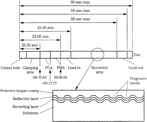
FIGURE 7.26 A CD-R disc holds data in pregrooved tracks. Data is permanently written into an organic dye-recording layer. The PCA area is used to calibrate the writing laser, and the PMA holds a temporary table of contents.
CD-R discs that are used to record CD-Audio data can be played in Red Book players. However, they differ from prerecorded CD-Audio discs. All user data is recorded as a reflectivity change in a pregrooved track. Two areas are written to the inner portion (22.35 mm to 23 mm radius) of the disc before the Red Book lead-in radius, as shown in Fig. 7.26. Because these areas are inside the normal lead-in radius, conventional CD players do not read them. The PMA (program memory area), starting at -13 seconds (-00:13:25) relative to the start of the lead-in at 0 seconds, contains data describing the recorded tracks, a temporary TOC, as well as track skip information. When the disc is finalized, this data is transferred to the TOC. Disc-at-once (DAO) recording, described below, does not use the PMA area.
In addition, the PCA (power calibration area), starting at -35 seconds (-00:35:65), allows the laser to automatically make an optimal power calibration (OPC) test recording to determine proper laser power for data recording. The PCA contains a test area and a count area. The count area keeps track of available space in the test area; it contains 100 numbered partitions, each being one ATIP (absolute time in pregroove) frame long. Calibration test data at different (perhaps 15) power levels is written to one partition. This data is read back and an analog signal (not an error rate) from each test recording is compared to an optimal value and used to determine writing power. This is usually performed once each time a disc is loaded, and a count is incremented (up to 100) by filling a count area partition with random data. After this count is reached, no additional data can be written to the disc, even though there may be an open data area. Thus, only 100 recording operations are available; in some recorders, the count is filled after 100 insertions of a given disc. Several methods to more effectively use the count area, and increase recording sessions, have been devised. In some drives, the laser power is continually monitored and adjusted using a method known as Running OPC. The pregrooved program area holds user-recorded information such as track numbers, and start and stop times. A recording is complete when a lead-in area (with TOC), user data, and lead-out area have been written. A maximum of 99 tracks can be recorded on a disc.
As with prerecorded CDs, CD-R discs are built on a polycarbonate substrate, and contain a reflective layer and a protective top layer. However, they are otherwise substantially different. A recording layer comprising an organic dye is sandwiched between the substrate and reflective layer (see Fig. 7.26). During manufacture, it is applied by spin coating and cured. Together with the reflective layer, it allows a typical in-groove reflectivity of 73% and a carrier-to-noise ratio (CNR) of 47 dB. To achieve the minimum 70% reflectivity standard of CD, as the beam passes through the recording layer and substrate twice, a gold or less-costly silver halide reflective layer is typically used. The dyes employed would corrode an aluminum layer as normally used in prerecorded CDs. The thickness of the metal layer is typically 50 nm to 100 nm. A CD-R disc may look like a regular CD, but is usually distinguished by its recording layer that appears green, yellow-green, or blue. (A gold metal layer is often distinguishing as well; in some cases, when a silver layer is used, it is topped by gold paint.)
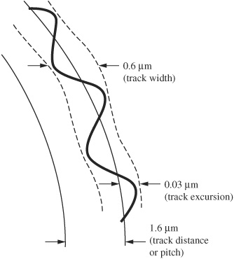
FIGURE 7.27 The CD-R pregroove track is modulated with a ±0.03-μm sinusoidal wobble with a frequency of 22.05 kHz.
Unlike prerecorded CDs, CD-R discs are manufactured with a pregrooved 1.6-μm pitch spiral track, used to guide the recording laser along the track; this greatly simplifies recorder hardware design and helps ensure disc compatibility. Drives maintain radial position by detecting an 8% reduction in reflected intensity that occurs because of diffraction when a beam is correctly tracking the pregroove. The 0.6-μm wide track is physically modulated with a ±0.03-μm sinusoidal wobble with a frequency of 22.05 kHz as shown in Fig. 7.27. The wobble allows the recorder to control disc CLV rotation speed (a task accomplished with Red Book discs from the prerecorded data). Furthermore, the 22.05-kHz groove wobble excursion is frequency modulated with a ±1-kHz signal; this is used to create an ATIP absolute time clocking signal. A writing drive reads the ATIP in the lead-in area to determine recommended write power and other information such as write strategies and allowable speeds needed to optimize recording quality. ATIP also specifies the maximum start of the lead-out, which sets recording capacity. Track velocity is set according to disc capacity; for example, 63-minute discs use a 1.4 m/s track velocity and 74-minute discs use 1.2 m/s.
The recording mechanism itself can be described as heat-mode memory. Laser light is used to create heat to affect the change in the recording media. For example, an 8-mW laser spot power focused to a diameter of 1 μm yields a power density of 1 × 10¹⁰ W/m2; the temperature can rise hundreds of degrees in a microsecond. The recording layer is a photo absorption surface which absorbs this heat energy from the recording laser. A 1 × writing laser beam nominally with 4 mW to 8 mW of spot power (higher power is used for faster writing speeds, for example, 40 mW at 50 ×) and a wavelength of 775 nm to 795 nm passes through the polycarbonate substrate, and heats the organic dye recording layer to approximately 250°C, causing it to melt and/or chemically decompose to form a depression or mark in the recording layer. These depressions or marks create the decreased change in reflectivity (for example, 75% to 25% for an 11T pit) required by standard CD player pickups. During readout, the same laser, reduced to 0.5 mW of spot power, is reflected from the data surface and its changing intensity is monitored. The result is an eye pattern and modulation amplitude essentially identical to that of prerecorded CDs.
Generally, three types of organic dye polymers are used to form the recording layer: cyanine, phthalocyanine, or metal azo. These dye polymers are all chemically tuned to absorb light at 780 nm. Metal-stabilized cyanine-based media are usually recognized by an emerald green or blue-green color when a gold metal layer is used; cyanine dye is actually intense blue in color. The green appearance is a combination of the blue dye and gold metal layer; when a silver metal layer is used, with its wavelength independent reflectivity, the cobalt blue color is apparent. When heated by the writing laser, the dye degrades to create a mark with decreased optical reflectivity. Very generally, because the CD-R standard was originally devised using cyanine dyes, discs using cyanine dye are reliable in a wide range of recorders and laser powers, and at a wide range of writing speeds. In addition, cyanine dye has a relatively broad range of sensitivity to light resulting in a broader spot power margin for the writing laser (6.0 mW ± 1.0 mW). This makes cyanine more suitable for a range of recording speeds and laser powers, and also offers greater compatibility. Generally, when writing to cyanine, recorders can use longer laser pulses to create 3T–11T marks.
Phthalocyanine-based media have a yellow-green or gold color appearance (it is colloquially called “gold”) when using a gold metal layer; the dye itself has a semi-transparent, nearly colorless yellow-green color. An advanced phthalocyanine dye is also used; it has an aqua color. During recording, the heated dye layer spot melts and shrinks, and the polycarbonate substrate expands to create a pit or mark. Very generally, phthalocyanine media is said to have greater longevity because it is stable and less sensitive to ordinary light. However, this lower sensitivity results in a small spot power margin for the writing laser (5.0 mW ± 0.5 mW), thus the writing speed and laser power must be more carefully controlled. Generally, when writing to phthalocyanine, recorders can use shorter pulses to create 3T–11T marks.
In some cases, metallized azo dye is used as the recording layer in CD-R media; its deep blue color is preserved when backed with a silver layer, and it appears green when backed by a gold layer. Even discs that use the same type of recording layer material can perform differently. Variations in recording layer thickness, reflective layer thickness, and different protective layers can affect disc-recording characteristics.
Organic dye layers are affected by aging. The dye layer will deteriorate over time because of oxidation and material impurities. In addition, the organic dye is sensitive to ultraviolet light and will degrade. Cyanine dye is more prone to degradation than phthalocyanine, which is inherently stable. To evaluate life expectancy of CD-R discs, discs are subjected to a variety of conditions that accelerate aging. For example, unrecorded and recorded media can be subjected to 65°C and 85% RH (relative humidity) for 2 months. (This equates to a 45-year duration at 22°C and 55% RH.) Discs can also be subjected to bending and scratch tests. Criteria such as BLER, E22, E32, and burst errors, described in Chap. 5, can be measured to determine end-of-life. In one test, errors were higher on media recorded after age testing than on media recorded prior to testing. Age testing degraded the recordability of the media more than its storage capability. Both unrecorded and recorded media should be stored in clean jewel cases in a stable environment of 10 to 15°C and 20 to 50% RH, and protected from sunlight and other radiation courses.
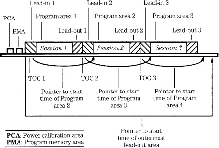
FIGURE 7.28 CD-R multisession recordings form a series of sessions across the disc surface, each with its own lead-in, program, and lead-out areas.
Shelf life of cyanine media is said to be from 10 to 100 years with nominal storage conditions. The typical BLER error rate is less than 20 per second, well below the Red Book CIRC tolerance of 220. In an accelerated aging test, the life expectancy of phthalocyanine discs was calculated to be 240 years. Ultimately, human carelessness, resulting in scratches, is probably the single biggest threat to CD-R longevity. The U.S. Mail is selectively irradiated by high-energy electronic beams. Irradiation can tint polycarbonate substrates, decrease reflectance, and increase error rates. However, radiation-induced errors are small and are corrected by error-correction codes; during testing, no uncorrectable errors resulted.
The Orange Book Part II defines both single session (regular) and multisession (hybrid) recording; a session is defined as a recording with lead-in, data, and lead-out areas. With single session recording, sometimes called disc-at-once (DAO) recording, a disc is recorded in its entirety, without interruption. The recorder records a TOC in the lead-in portion of the disc, data tracks, and a lead-out area, so any standard player can read the disc. A PMCD (premastered CD) recording used as a master is an example of a DAO application. Tracks can be recorded back to back without a gap; this allows for crossfades between tracks. When recording DAO, it is recommended to first create a disc image, a file that includes all the data to be recorded.
Alternatively, track-at-once (TAO) recording allows single or multiple tracks to be written in a session; this is the most widely supported recording method. After the program tracks are written, the recorder writes the TOC and lead-in areas, and lead-out areas. The writing laser is turned off after each track; this creates a gap between tracks. A partially recorded disc can be played on the CD-R recorder, but cannot be played on a CD-Audio player until the session ends when the final TOC and lead-out areas are recorded. Most recorders permit an unwanted track (such as a false start) to be marked and deleted from the TOC so the CD-R player (and CD-Audio players recognizing skip-ID flags) will skip over it. Recorders using TAO can also write a single-session CD-R.
The Orange Book Part II also specifies multisession (hybrid) recording in which sessions can be recorded one or a few at a time. Tracks can be written one at a time and recording can be stopped after each track. Separate recording sessions are permitted, each with its own lead-in TOC, data, and lead-out areas, as shown in Fig. 7.28. This session structure is required so Red Book players will recognize the beginning and end of segments. Each time a session is created, about 13.5 Mbytes (6750 blocks) of capacity is lost to lead-in and lead-out areas (22 Mbytes is used for the first session). The lead-in for a session occupies about 8.8 Mbytes, and the lead-out for a session occupies about 4.4 Mbytes (the lead-out for the first session occupies about 13.2 Mbytes). Clearly, this is inefficient for adding small amounts of data. TAO recorders allow multisession recording, in addition to single-session recording. With TAO recording, multiple tracks can be written to a session, adding data one track at a time; no lead-in or lead-out is written until the session is closed. This saves disc space, but the session cannot be read by most players until the session is closed. Older CD-ROM drives and all CD-Audio players can read only the first session on a multisession disc. Thus, multisession recording typically is not used for CD-R audio discs. Photo CD and some CD-ROM titles, are examples of multisession discs.
In multitrack recording, data is appended to a disc in tracks that are at least 2 seconds long (about 300 sectors or 700 kbytes). Tracks can contain one or more files and the session is left open between write operations. Individual tracks are separated by a 150-sector gap. After a track is written, track numbers and timings are written in the PMA; a link block is written where the laser turns off before it is temporarily moved to the PMA. When the session is closed, the TOC is written, the link blocks are hidden, and the disc can be removed from the drive.
By using the CD portion of the Universal Disk Format (CD-UDF), CD-R discs can perform packet writing so that small amounts of data can be efficiently written. For example, whereas multisession recording requires large data overhead, packet-writing overhead might consume less than 4 Mbytes per disc. Packet writing can be performed on CD-R media, making them functionally similar to small hard-disk drives. Data in a file can be appended and updated without rewriting the entire file. Because the data structures are so small, buffer underrun is alleviated. Packets of data (variable or fixed length) are written to a disc without closing either a track or a session, and without updating the TOC or PMA. Instead, system information about the partial track is placed in the Track Descriptor Block in the pre-gap before the track. A packet contains user data along with associated link blocks. Special blocks called run-in and run-out allow a recorder to synchronize data, and they also contain interleaved data from other blocks. Written data comprises a link block, four run-in blocks, user data, and two run-out blocks. Fixed-length packets allow data to be randomly erased and rewritten without accounting for different packet size; however, disc capacity is decreased to about 500 Mbytes. Variable-length packets allow greater disc capacity because mapping is fixed when data is written. Not all CD recorders support packet writing. Packet writing, also called block append, is defined in the Orange Book Part II for CD-WO. Packet writing is also defined in the ISO 13490 specification. The UDF Bridge file format is used in DVD, as described in Chap. 8.
Both stand-alone and peripheral CD-R recorders have been developed. Stand-alone recorders allow users to record discs and perform simple editing of tracks and subcode. These are intended for audio use and apply Serial Copy Management System (SCMS) data to the recorded program. Peripheral CD-R recorders interface to a host computer via a SCSI or other interface; many recorders are packaged as half-height drives. The recorders operate at speeds much faster than real time, generating all synchronization, header, CIRC, and EFM processing required by the CD standard. Depending on the software package, various degrees of data manipulation are possible; for example, a software application can consolidate fragmented files and specify the physical location of CD-ROM data on a disc so that retrieval time is shorter. When a CD-R disc is authored according to the ISO 9660 file format, the disc can be read on multiple platforms.
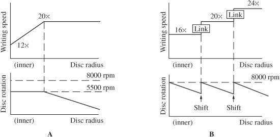
FIGURE 7.29 To optimize data transfer speed, disc drives can employ several techniques. A. In a PCAV drive, inner radii are read using CAV and outer radii are read using CLV. B. In a ZCLV drive, different CLV speeds are used across the disc radius.
Real-time recorders operate at a 150-kbps rate; however, higher-speed recorders are widely used (higher laser power is needed at high speeds). Higher-speed recorders may provide lower error rates than single-speed recorders; this may be because in single-speed writing, the laser remains focused for a longer time and an unwanted annealing process may be caused by the added heat. Recorders with OPC can avoid this effect. Discs suitable for high-speed recording are specially approved for reliability.
At 1 × speed, a disc spins at about 539 rpm when the head is placed on the inner radius and it slows to 210 rpm at the outer radius. At 16 ×, for example, the speeds are about 8000 and 3200 rpm respectively; a 50 × drive might reach speeds in excess of 12,000 rpm. CLV is efficient when reading an audio disc at 1 × speed; it is relatively easy to change speeds when accessing different tracks at different radii. However, at high speeds, it is difficult to quickly change high disc speeds over a range of radii. To accommodate high disc velocities, some disc drives use partial constant angular velocity (PCAV) to spin the disc at a lower fixed speed near the inner radius, and then shift to CLV near the outer radius. For example, a 20 × drive might start reading the inner radius at 12 × using a CAV method, as shown in Fig. 7.29A. As reading progresses and the pickup moves outward, the transfer rate increases. When a 20 × speed is reached, the drive switches to CLV and the data rate is constant at 20 × (3000 kbps). Some drives use zoned constant linear velocity (ZCLV), in which different fixed writing speeds (operating in a CLV mode) are used in discrete regions of the disc as shown in Fig. 7.29B. For example, a 24 × drive might use 16 ×, 20 ×, and 24 × in different radii of the disc. Writing is suspended as the drive shifts speeds; to provide writing continuity, data is held in a buffer. In any high-speed drive, high-speed writing is not possible across the entire disc radius.
In some high-speed drives, the laser beam is diffracted to create multiple laser spots, one spot per groove. Multiple pickups receive simultaneous data, thus increasing the effective data-reading rate, particularly when reading sequential data.
Discs designed for high-speed writing are designed to accept the thermal effects of higher-power lasers, and the substrate and track must be mechanically sound and accurate. High-speed disc writers must use modified write strategies to allow for thermal effects; for example, the drive can read parameters encoded on the blank media to optimize the level and duration of the power region that initiates a recorded mark. The drive must also be mechanically able to withstand high velocities. For example, vibration caused by an eccentric or unbalanced disc must be minimized. Drives are relatively unaffected by vibration when reading because autotracking can use a robust error signal based on large (60%) changes in intensity of reflected light. However, drives are more sensitive to vibration when writing because tracking is performed with push-pull methods that must rely on small (5 to 10%) variations in reflected light intensity from the unrecorded pregroove. Also, contamination on a disc surface is relatively unimportant when reading data, but any obstruction to a writing laser will result in a permanent error. The Orange Book specifies that jitter for CD-R discs should be less than 35 ns.
Two types of CD-R discs are sold: for computer use, or for music use. The discs are otherwise physically identical, but during mastering (of the blank) a mandatory Disc Application Code is embedded in the ATIP information contained in the pregroove lead-in area. Three types of discs are defined: Types 1a and 1b for restricted use and Type 2 for nonrestricted use. Type 1a is used for CD-ROM or professional audio recording. Type 1b is used for special purpose applications such as a Photo CD and can only be written to by those specialized recorders. Type 2 discs are for consumer audio recording. Stand-alone consumer CD-R audio recorders will not record unless that code is present. Thus, only music-use discs can be used; their higher cost is used to compensate artists. Computer-use CD-R discs are used in CD-R drives connected to a host computer; these discs can also be used to record music to a disc, using computer-use discs. Clearly, copyright laws should be observed. Music-only CD-R discs are sometimes referred to as CD-R-DA (Digital Audio).
Although CD writing on a PC is relatively simple, some care must be taken; the computer must provide a steady stream of data, while simultaneously interleaving, error-correcting, and formatting the data. Many systems can transfer data from either tape or hard disks to the recorder, and can produce CD-Audio, CD-ROM (including CD-ROM/XA), and Photo CD discs. Generally, a hard-disk drive with fast access (10-ms seek time) is required, connected to the PC via a fast (10 to 20 Mbytes/s) interface to the PC bus. During recording, any interruption in the data stream at the recording laser will render a disc unusable. Most CD-R recorders contain a cache memory (1.2 to 4 Mbytes); this helps prevent data stream problems from buffer underrun. Some users recommend several measures to help ensure successful writing: partition the staging drive to hold the disc image, create a real ISO image file (as opposed to a virtual image comprising lookup addresses of data to be written) of the data, defragment the hard drive, and test before writing. Some users recommend hard-disk drives with embedded servo tracks so that automatic thermal recalibration will not interrupt the data stream; alternatively, hard drives with unobtrusive recalibration procedures can be used. In addition, network services, auto-answer fax software, sound utilities, screen savers, virus checkers in resident memory, and TSR (terminate and stay resident) programs should be turned off during recording to prevent glitches in the bitstream.
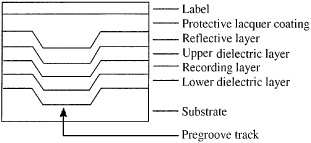
FIGURE 7.30 The CD-RW recording layer is sandwiched between two dielectric layers.
CD-RW
The Compact Disc ReWritable (CD-RW) format allows data to be written, read, and erased and rewritten. The format is officially named CD-E and it is described in the Orange Book Part III standard, issued in 1996. A CD-RW drive can read, write, and erase CD-RW media, read and write CD-R media, and read CD-ROM and CD-Audio media. The data can comprise computer programs, text, pictures, video, audio, or other files. CD-RW disc capacity is about 700 Mbytes. A CD-RW disc has an embedded aluminum layer and a recording layer that appears gray. Altogether, there are five layers built on the polycarbonate substrate: a dielectric layer, a recording layer, another dielectric layer, a reflective aluminum layer, and a top acrylic protective layer, as shown in Fig. 7.30. This phase-change recording technology allows thousands (on the order of 105) of rewrite cycles.
As in CD-R, the writing and reading laser follows a pregroove across the disc radius. However, whereas CD-R uses a dye-recording layer, the CD-RW format employs a phase-change recording layer comprising an alloy of silver, indium, antimony, and tellurium. This metal exhibits a reversible crystalline/amorphous phase change when recorded at one temperature and erased at another, as described in Chap. 6. The recording layer on the blank disc is in crystalline form; it is translucent thus light is reflected from the metal layer above it. Data is recorded by directing a laser (8-mW to 14-mW spot power) to heat an area of the crystalline layer to a temperature above its melting point (500 to 700°C). When the area revitrifies rapidly, it becomes amorphous and absorbs light, and the decreased change in reflectivity can be detected. A low-power laser (perhaps 0.5-mW spot power) is used to read data.
Because the crystalline form is more stable, the material will tend to change back to this form; thus, data can be erased using an annealing process. When the recording surface is heated by a lower laser spot power of perhaps 4 mW to 8 mW to its transition temperature (200°C) and cooled gradually, it returns to its original crystalline state. Unlike dye-polymer technologies, phase-change recording is not wavelength-specific.
Rewriting is accomplished through direct overwriting. Rather than completely erase a disc side, this “on the fly” erase feature allows the last recorded audio track to be erased simply by erasing the subcode reference to that track while leaving the recorded data in the recording layer. With this method, recorded tracks can be erased individually, working sequentially backward from the last recorded track, to provide editing control without requiring total erasure.
A technique called Running Optical Power Calibration determines the correct laser power levels when individual discs are loaded, and monitors and adjusts the power level to compensate for surface contamination such as fingerprints. Unlike CD-R recording in which the laser is turned on for the duration of the pit formation, in CD-RW, the laser is repeatedly switched between its write or erase power, and a low bias power (less than 1 mW) that is equal to the power used to read the disc. This switching is performed so that the recording alloy layer will not accumulate excess heat, thus creating overly large marks. The dielectic layers comprise silicon, oxygen, zinc, and sulfur; they control the optical response of the media and increase the efficiency of the laser by containing the heat that is used to record data on the recording layer. They also thermally insulate and protect the pregroove, substrate and reflective layers, and mechanically restrain the recording layer material.
As with CD-R, two types of CD-RW discs are sold: for computer use, or for music use. The discs are physically identical, but a permanently recorded flag is placed on music-use discs; stand-alone consumer CD-RW audio recorders will not record unless that flag is read. Music-only CD-RW discs are sometimes referred to as CD-RW-DA (Digital Audio).
The reflectivity of CD-RW discs is only about 15 and 25% (amorphous and crystalline states, respectively). They generally cannot be played in conventional CD players (many DVD players do play CD-RW discs) or CD-ROM drives. A CD-RW drive is required, or a MultiRead drive capable of reading lower reflectivity discs. Such drives contain an automatic gain control (AGC) circuit to compensate for the lower reflectivity and signal modulation. The AGC boosts the gain of the signal output from the photodiodes. To facilitate this, CD-RW discs carry a code that identifies them as CD-RW discs to the player. CD-RW drives are commonly found as PC peripherals. Software supports TAO, DAO, and multisession recording. When CD-RW discs are appropriately formatted, the CD-UDF specification permits easy file-by-file rewriting. In particular, users can write to the CD-RW drive by simply dragging and dropping.
CD-MO
The Orange Book Part I defines a Compact Disc Magneto-Optical (CD-MO) standard; data can be written, erased, and rewritten. Two types of discs are defined: a disc with a premastered area (recorded with pits) containing CD-ROM data plus a writable area, and a disc that is completely writable. Because writable data is read via changes in light polarization rather than intensity, CD-MO discs are not playable in CD-Audio or CD-R drives (however, CD-MO drives can play CD-Audio and CD-R discs). A CD-Audio player can read the premastered area on a CD-MO disc. In some ways, the MiniDisc was an evolution of the CD-MO specification.
CD-i
The Compact Disc Interactive (CD-i) standard was devised as a product-specific application of the CD-ROM format. CD-i permits storage of a simultaneous combination of audio, video, graphics, and text, and defines specific data formats for these. In addition, titles can function with real-time interactivity. For example, a CD-i dictionary might contain a word and its definitions, as well as spoken pronunciation, pictures, and translations into foreign languages. The CD-i standard, codified in the Green Book (issued in 1986), defines how each type of information is encoded as well as logical layout of files on the disc. It also specifies how hardware reads discs and decodes information.
The CD-i data format is derived from the CD-ROM Mode 2 format. CD-i data is arranged in 2352-byte blocks, as in the CD-ROM/XA format. The CD-i format accepts either PCM or ADPCM (adaptive differential pulse-code modulation) data. The full-motion video (FMV) extension allows storage of 74 minutes of full-motion digital video and stereo audio. The MPEG-1 coding standard is used to reduce the video bit rate to 1.15 Mbps and the audio rate to 0.22 Mbps; lower rates can also be used. CD-i players can also play Video CDs coded with MPEG-1. MPEG-1 audio is described in Chap. 11 and MPEG-1 video in Chap. 16. To ensure universal compatibility, dedicated hardware and interfaces are defined. The CD-Bridge format adds information to a CD-ROM/XA disc so it can be played on a CD-i player. Bridge tracks use Mode 2 data, tracks are listed in the TOC as a CD-ROM/XA track, and block layout is identical to CD-i and CD-ROM/XA. The Photo CD is an example of a Bridge disc. The CD-i format did not enjoy success among its targeted consumers.
Photo CD
The Photo CD is used to professionally store, manipulate, and display photographic images. Photographs can be viewed or reproduced as high-quality prints of images using a color printer. The 35-mm version of the Photo CD provides three to four times the resolution required in any high-definition television (HDTV) standard. Conventional photographic images can be scanned to the Photo CD, with 2048 scan lines across the short dimension of a 35-mm frame, with 3072 pixels on each line to yield a 3:2 aspect ratio. Data compression and decomposition are used to increase storage efficiency. During authoring, high-resolution image files are subjected to a 4:1 data reduction. In addition, file sizes can be reduced without significant visual loss by using chroma sub-sampling to take advantage of limitations in human visual perception. The Photo CD was developed by Kodak and is defined in the Beige Book.
Photo CD discs conform to the Orange Book Part II standard and are physically identical to CD-R audio discs; however, different data headers make them incompatible. Data blocks are written according to the CD-ROM/XA, Mode 2, Form 1 standard. Because discs use the CD-Bridge format, they are playable on CD-ROM/XA players. Because the Orange Book Part II permits additional multisession recording to a disc, images can be added over time. Pacs initially recorded on a disc are structured as a file using the ISO 9660 structure. Subsequently recorded Pacs use a CD-R Volume and File Structures format, using the multisession method. All Pacs are addressed through the block-addressing method used by CD-ROM discs and defined by the ISO/IEC 10149 standard. Because the Photo CD adheres to the CD-ROM/XA format, audio and video data can be interleaved; in this way, a soundtrack can accompany visuals. The Picture CD consumer format similarly stores photographic files on a CD-R disc; it provides 1024 × 1536 resolution using JPEG compression. The disc also contains software used to view and edit the photographs.
CD + G and CD + MIDI
The CD + G and CD + MIDI formats were devised to encode graphics or MIDI software on CDs, in addition to regular audio data. Special hardware or software is required to access this data. Eight subcode channels are accumulated over 98 frames; thus, each 98-bit subcode word is output at a 75-Hz rate. Subcode synchronization occupies the first two frames, thus a subcode block contains eight channels with 96 data bits. This data block is called a packet, and each quarter of a packet is called a pack. A pack is generated every 3.3 ms. Only P and Q are reserved for audio control information. Over the length of a CD, the remaining channels, R to W, provide about 25 Mbytes of 8-bit data. Utilization of that capacity has been promoted as CD + G or CD + Graphics, and CD + MIDI, sometimes known as CD + G/M. The player decodes the graphics or MIDI data separately from the audio data. In CD + G discs, data is collected over thousands of CD frames to form video images or other data fields. For example, a CD + G audio disc can contain video images, liner notes, librettos, or other information. Because video images require a large amount of data for storage, CD + G images provide limited resolution.
In the CD + MIDI application, MIDI (Musical Instrument Digital Interface) information is stored in the subcode field, and output synchronously with the audio playback. External MIDI instruments can synchronize to the melody or other musical parameters of an encoded disc. The subcode capacity is sufficient to store up to 16 channels of MIDI information. MIDI information can be supplemented with graphics information; for example, music notation could be supplied. Another variation can encode music notation in the subcode area to allow print out of sheet music. CD + G/M discs are compatible with any CD player, but only players equipped with CD + G/M output ports can retrieve the information from the disc. Alternatively, an external decoder can be connected to any CD player with a digital output port, provided that the full subcode data is available from the port. CD + G is sometimes used for karaoke applications.
CD-3
In addition to regular 120-mm-diameter CD discs, the CD-3 format describes 80-mm-diameter discs. The name derives from the approximately 3-in diameter. This small size promotes greater portability and the format is useful for short audio programs. A CD-3 disc holds a maximum of 20 minutes of music. Because a CD data track begins at the innermost radius, CD-3 discs are compatible with regular discs and players. Some players have concentric rings in their disc drawers to center both diameter discs over the spindle. The CD-3 format is also used to hold over 200 Mbytes of CD-ROM data. The CD-3 format is also used for CD-R and CD-RW discs.
Video CD
The Video CD format is an outgrowth of the CD-i standard; full-motion video was added to the original CD-i standard and that feature was subsequently revised in 1992 to form the Video CD standard. The Video CD uses the MPEG-1 coding standard for audio and video. The audio signal is coded with the Layer II standard at 44.1 kHz. A disc stores about 74 minutes of full-motion digital video and audio; a feature film is placed on two discs. The video decoder chip permits full-motion video (FMV) to be shown at either 29.97 (NTSC) or 25 (PAL/SECAM) frames per second at 352 pixels by 240 lines and 352 pixels by 288 lines, respectively, one-fourth the resolution of DVD’s normal mode. The Video CD may be shown as a quarter-screen image. The video bit rate is 1.15 Mbps and the audio bit rate is 0.22 Mbps. The Video CD format is a CD-ROM/XA Bridge disc, Mode 2, Form 2; this allows a Video CD to play on a CD-ROM drive. A Video CD disc will not play on a CD-Audio player, but will play in many DVD players. Video CD is described in the White Book; version 1.0 of this specification was originally developed in 1992 for karaoke discs and in 1995 it was extended to version 2.0, which supported interactive video. The Video CD is different from the CD-Video format, now abandoned. The MPEG-1 video algorithm is discussed in Chap. 16. MPEG-1 audio is discussed in Chap. 11.
The Super Video CD (SVCD) is an enhanced version of the Video CD designed primarily for higher-quality movie playback. SVCD uses MPEG-2 coding for video compression to store about 70 minutes on a disc. The NTSC resolution is 480 × 480, and PAL resolution is 470 × 576—about three-fourths that of DVD’s normal mode. Dual mono, stereo or 5.1-channel soundtracks can be used at bit rates ranging from 32 kbps to 384 kbps using MPEG-1 Layer II or MPEG-2 multichannel codecs. Uncompressed audio cannot be stored. The maximum data rate is 2.2 Mbps by virtue of a 2 × drive. However, at the higher data rate, playback time is halved to about 35 minutes; a movie might occupy three discs. Copy Generation Management System (CGMS) copy protection can be enabled. SVCD’s development was sponsored by the Chinese government as a low-cost alternative to DVD. Other technical aspects were derived from the Video CD format and the China Video CD (CVD). The SVCD specification was ratified by the China National Committee of Recording Standards in September 1998. SVCD is also standardized in the IEC-62107 document. A similar specification, the Chao-Ji (“Super”) VCD standard, was developed to support both China Video CD and SVCD; many SVCD players and changers support the Chao-Ji standard and most discs use the SVCD format. The DSVCD (Double SVCD) format uses a smaller track pitch to permit longer high-quality playing times of about 60 minutes.
Super Audio CD
When the Compact Disc was launched in 1982, it was rightly heralded as a data carrier of immense storage capacity. However, over time the CD seemed increasingly small. Moreover, some audiophiles argued that its specifications constrained audio fidelity. In particular, the CD was insufficient for the large file sizes and high bit rates required by surround sound and high sampling frequency audio. In 1999, Philips and Sony introduced the high-density Super Audio CD standard, known as SACD. The SACD format supports discrete-channel (two-channel and multichannel) audio recordings, using the proprietary one-bit Direct Stream Digital (DSD) coding method. DSD uses a high sampling frequency and achieves a flat frequency response to 100 kHz and a dynamic range of 120 dB in the 0- to 20-kHz band.
SACD players can play both SACD and CD discs. SACD is not compatible with the DVD or Blu-ray formats. The mechanical and optical properties of an SACD disc are similar to those of a DVD-5 disc; however, the logical layout of content, the data format, and the copy protection measures are different. DSD data is not playable in standard DVD or Blu-ray drives, but a CD layer, if present on an SACD disc, is playable. Some players may include decoders to accommodate multiple disc formats. Other data such as text and graphics (but not video) can be included on an SACD disc; this content follows the Blue Book “Enhanced CD” standard. The SACD standard is sometimes known as the Scarlet Book, published in March 1999.
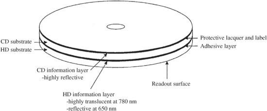
FIGURE 7.31 A hybrid SACD disc contains two data layers (high-density and CD). The two layers are bonded together to form a disc with a thickness of 1.2 mm. (Verbakel et al., 1998)
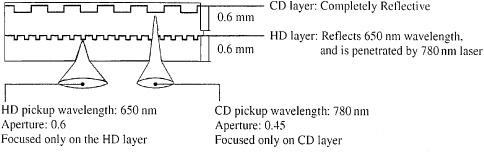
FIGURE 7.32 Both the high-density layer and CD layer in a hybrid SACD are read from one side by a laser. The high-density layer is semi-reflective, while the CD layer is fully reflective.
Disc Design
SACD discs use the same dimensions as a CD: 12-cm diameter and 1.2-mm thickness. The laser wavelength is 650 nm, the lens NA is 0.60, the minimum pit/land length is 0.40 μm, and the track pitch is 0.74 μm. (The pertinent CD figures are 780 nm, 0.45, 0.83 μm, and 1.6 μm.) Software providers may choose from three disc types specified in the SACD format: single-layer, dual-layer, and hybrid disc construction. The single-layer disc contains one layer of high-density DSD content (4.7 Gbytes); for two-channel stereo, this provides about 110 minutes of playing time. The dual-layer disc contains two layers of high-density content (8.5 Gbytes total). The hybrid disc is a dual-layer disc that contains one layer of high-density DSD content (4.7 Gbytes) and one layer of Red Book compatible stereo content (680 Mbytes), as shown in Fig. 7.31. The semi-reflective high-density layer must be reflective (readable) at the 650-nm wavelength of SACD, and transparent at the 780-nm wavelength used by conventional CD players; in other words, it acts as a color filter. The high-density layer is 0.6 mm from the readout surface and the CD layer is 1.2 mm from the surface. An SACD player can read both layers, and a CD player can read the CD layer.
In dual-layer discs, two 0.6-mm substrates are bonded together. In all implementations, there is only one data side. A semi-reflective layer (20 to 40% reflective and approximately 0.05 μm in thickness) is used on the embedded inner data layer; in some cases, a silicon-based dielectric film is used. A fully reflective top metal layer (at least 70% reflective and approximately 0.05 μm in thickness) is used on the outer data surface. This surface is protected by an acrylic layer (approximately 10 μm in thickness) and a printed label. Care must be taken to seal a hybrid disc to limit water absorption and evaporation from the substrate; unequal absorption between the two disc sides could cause disc warpage. The back side is inherently protected by a metal layer and a lacquer layer while the front side is nominally unprotected, thus a front-side transparent silicon-based coating (10 nm to 15 nm) is needed. A hybrid disc in which a dual pickup (650 nm and 780 nm) is used to read both SACD and CD data is shown in Fig. 7.32.
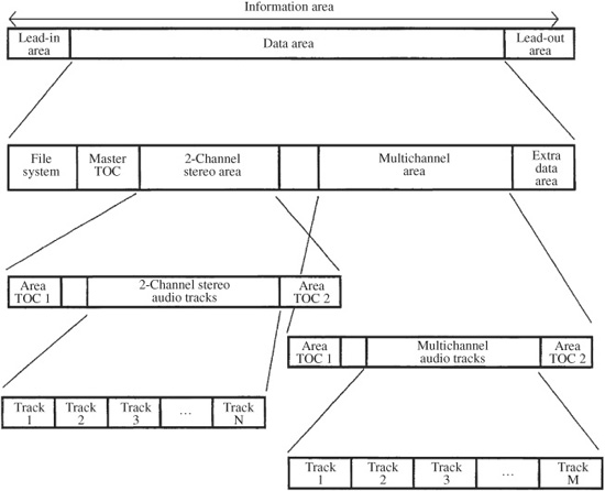
FIGURE 7.33 The SACD high-density data layer is designed to carry both two-channel and multichannel audio data.
The data on an SACD disc is grouped into sectors of 2064 bytes. This comprises: Identification Data (ID) of 4 bytes, ID Error Detection (IED) of 2 bytes, Reserved of 6 bytes, Main Data of 2048 bytes, and Error Detection Code (EDC) of 4 bytes. During encoding, following scrambling, 16 sectors form an error-correction code block, which is processed with a scheme using a Reed–Solomon Product Code. Rows of ECC blocks are interleaved and grouped into recording frames. Frames undergo EFMPlus modulation. Data is then placed in Physical Sectors and recorded to disc.
The radius of the high-density layer is segmented for different kinds of data, as shown in Fig. 7.33. The innermost radius contains the disc lead-in area, followed by the data area. It is divided into several areas including a Master Table of Contents (Master TOC) containing information on tracks and timing, as well as text data on the title and artist. The Master TOC is stored in three places (sectors 510, 520, and 530) to ensure readability. The next two radial areas are given to two-channel and multichannel recordings (up to six channels). The two-channel and multichannel areas use the same basic structure. The Area TOC for each audio area is placed at the beginning and end of each area. They contain track, sampling frequency, timing, and text information about the tracks included in that section. The SACD standard permits up to 255 tracks. Audio tracks contain two types of streams: audio elementary stream and supplementary data elementary stream; they are multiplexed. In addition, there are sequences of audio frames each with a timecode, and supplementary data frames for pictures, text, and graphics; each frame represents 1/75 second. Following the audio tracks, there is an area for optional data such as text, graphics, and video. This data can only be accessed by a file system; its format is not specified in the SACD specification. The outermost radius holds the disc lead-out. SACD discs can be read using a hierarchical TOC, or by optionally using a UDF or ISO 9660 file system.
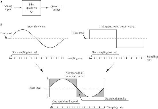
FIGURE 7.34 In principle, DSD coding is based on a one-bit quantization method. A. A one-bit quantizer produces a square wave output. B. The output square wave from a one-bit quantizer yields a large difference signal.
All SACD discs incorporate an invisible watermark that is physically embedded in the substrate of the disc. Virtually impossible to copy, the watermark is used to conduct mutual authentication of the player and the disc. SACD players read the watermark and will reject any discs that do not bear an authentic watermark. Visible watermarks on the signal side of the disc in the form of faint images or letters may also be employed. A process called Pit Signal Processing (PSP) uses a controlled array of pit widths to create both invisible and visible watermarks; user data stored as pit/land lengths is unaffected by this watermarking.
DSD Modulation
Whereas all CD discs carry PCM data, all SACD discs carry Direct Stream Digital (DSD) data, in which audio signals are coded in one-bit pulse density form using sigma-delta modulation. Most conventional analog-to-digital (A/D) converters use sigma-delta techniques in which the input signal is upsampled to a high sampling frequency. The signal is passed through a decimation filter and also quantized for output as a PCM signal at a nominal sampling frequency of 44.1 kHz (for CD) and up to 192 kHz (for DVD-Audio or Blu-ray). Likewise, many D/A converters use oversampling to increase the sampling frequency of the output signal, to move the image spectra from the audio band. As in PCM systems, DSD begins with a high sampling frequency, but unlike PCM systems, DSD does not require decimation filtering and PCM quantization in the recording process; instead, the original sampling frequency of 2.8224 MHz is retained. One-bit data is recorded directly on the disc. Unlike PCM, DSD does not employ interpolation (oversampling) filtering in the playback process. In other words, the basic DSD specification is based on the direct output of a typical sigma-delta A/D converter at 64 × 44.1 kHz.
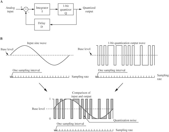
FIGURE 7.35 DSD coding uses a sigma-delta coding technique. A. A sigma-delta modulator uses negative feedback to subtract a compensation signal from the input. B. The output signal from a sigma-delta modulator is a pulse-density waveform.
DSD uses sigma-delta modulation and noise shaping. A simple one-bit quantizer is shown in Fig. 7.34A, and the output waveform resulting from a sine-wave input is shown in Fig. 7.34B. The shaded portion shows the difference error between the input waveform and the quantized output waveform. An example of a simple sigma-delta encoder is shown in Fig. 7.35A. The one-bit output signal is also used as an error signal and delayed by one sample and subtracted from the input analog signal. If the input waveform, accumulated over one sampling period, rises above the value accumulated in the negative feedback loop during previous samples, the converter outputs a 1 value. Similarly, if the waveform falls relative to the accumulated value, a 0 value is output. Fully positive waveforms will generate all 1 values and fully negative waveforms will generate all 0 values. This method of returning output error data to the input signal to be subtracted as compensation data is called negative feedback.
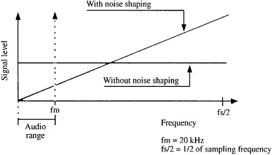
FIGURE 7.36 Noise-shaping algorithms are designed to reduce the low-frequency (in-band) quantization error, but also increase high-frequency (out-of-band) content.
Figure 7.35B shows an input sine wave applied to a sigma-delta encoder and the resulting output signal. The pulses of the output signal reflect the magnitude of the input signal; this is a pulse density modulation representation in which a 0 value has no pulse output while a 1 value does. The shaded portion shows the difference error; analysis shows that the volume of error is the same as in a simple quantizer; however, because the integrator (sigma) in the sigma-delta encoder acts as a lowpass filter, the amount of low-frequency error is reduced while the amount of high-frequency error is increased, as shown in Fig. 7.36. The system’s designers note that the ear is sensitive to very high-frequency signals only if they are correlated to lower in-band signals. At frequencies higher than 20 kHz, they state that signal-to-noise ratios become less important. Thus, they argue that the uncorrelated high-frequency shaped noise is perceptually unimportant. This noise shaping property can be developed with higher-order (perhaps 5th order) noise shaping feedback filters to further decrease error in the audible range of frequencies. In principle, a lowpass filter can decode sigma-delta signals. Such a low-pass filter would also remove high-frequency noise resulting from noise shaping. The principles of sigma-delta modulation and noise shaping are discussed more fully in Chap. 18.
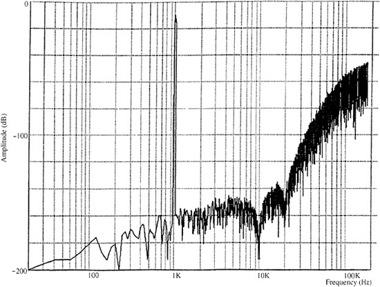
FIGURE 7.37 DSD coding used in the SACD format requires significant noise shaping to reduce low-frequency noise. However, this significantly increases high-frequency noise above 20 kHz.
The DSD modulation used in the SACD format uses a sampling frequency that is 2.8224 MHz. In other words, the analog signal is sampled at a 2.8224 MHz rate and each sample is quantized as a one-bit word. Overall, the bit rate is thus four times higher than on a CD. In principle, the Nyquist frequency is thus 1.4112 MHz. However, in practice, to remove high-frequency noise introduced by high-order noise shaping, the high frequency response is limited to 100 kHz or less by analog filters. As shown in Fig. 7.37, a significant noise-shaping component is present in the 100-kHz band, as anticipated by the SACD standard.
The SACD standard specifies that noise power in the 100-kHz band should be 20 dB below the standard reference level. When a 100-kHz lowpass filter is used, at a volume level that achieves a 100-watt output, this noise component is thus 1 watt or less. However, at higher volume levels, the SACD standard recommends that SACD players incorporate a lowpass filter with a corner frequency of 50 kHz and a minimum 30-dB/octave slope for use with most conventional power amplifiers and speakers. When making audio measurements of the SACD, a 20-kHz lowpass filter (such as the 3344A filter by NF Electronic Instruments with 60 dB of attenuation above 24.1 kHz) is recommended to avoid the effects of the shaped components in the higher frequency range.
The 2.8224 MHz (64 × 44.1 kHz) sampling frequency of the one-bit DSD signal can be converted to a variety of standard PCM sampling frequencies with integer computation. Division by 64 and 32 yields 44.1 and 88.2 kHz. Following multiplication by 5, division by 441, 294, and 147 yields 32, 48, and 96 kHz, respectively. Also, an extended sampling frequency of 128 × 44.1 kHz is possible.
DST Lossless Coding
A lossless coding algorithm known as Direct Stream Transfer (DST) is employed in the SACD format to more than double effective disc capacity. Eight DSD channels (six multichannel plus a stereo mix) on a 4.7-Gbyte data layer are allowed a playing time of 27 minutes, 45 seconds. With DST, a 74-minute playing time is accommodated, effectively increasing storage capacity to about 12 Gbytes. As with other lossless compression methods, the compression achieved by DCT depends on the audio signal itself. In one survey, DCT yielded a coding gain of 2.4 to 2.5 for pop music, and 2.6 to 2.7 for classical music.
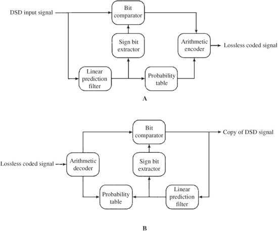
FIGURE 7.38 Direct Stream Transfer (DST) can be used for lossless coding of DSD data using an adaptive prediction filter and entropy (arithmetic) coding. A. DST encoder. B. DST decoder.
The DST encoder and decoder are shown in Fig. 7.38. DST uses data framing, an adaptive prediction filter and entropy coding. The use of lossless coding can be decided on a frame-by-frame basis; the flag information for the decoder is contained in each frame header. An area without any DST frames can be marked accordingly in the area TOC. DST coding yields variably sized frames; a buffer model is used to output a fixed bit rate. The theory of lossless coding is discussed in Chap. 10.
Player Design
SACD players play back both SACD and CD discs. Their design is similar to that of CD players. Dual laser pickups are required to operate at both the SACD 650-nm wavelength and the CD 780-nm wavelength. In some player designs, a single processor accepts the amplified RF signal from the dual pickup and performs clock signal extraction and synchronization, as well as demodulation and error correction for both CD and SACD signals. A servo chip controls the pickup and motor systems. CD data is passed along to the digital filter. SACD data is applied to the DSD decoder; this circuit first reads the invisible watermark, then intermittent data is rearranged and ordered in a buffer memory according to a master clock. This chip also reads subcode data, including TOC information such as track number, time, and text data.
DSD data is output as a one-bit signal at a frequency of 2.8224 MHz and applied to a pulse-density modulation processor in which the data signal is converted to a complementary signal in which each 1 value creates a wide pulse and each 0 value creates a narrow pulse. A current pulse D/A converter converts the voltage pulse output into a current pulse. This current pulse signal is passed through an analog lowpass filter to create the analog audio waveform. In some designs, this filter’s response measures -3 dB at 50 kHz.