
Chapter 1
Introducing Physical Computing
IN THIS CHAPTER
![]() Understanding how to use small computers
Understanding how to use small computers
![]() Using a Raspberry Pi to sense the environment around you
Using a Raspberry Pi to sense the environment around you
![]() Making your computer do physical things
Making your computer do physical things
We think it's more difficult to learn about the software (Python) than the hardware, which is why in the last several hundred pages we've focused on learning how to program in Python. But now it's time for you to learn how to make your computer do something with Python. Making your computer do mechanical things — and interact with the world around you — is called physical computing!
 In this chapter, we hook up various sensors and motors to a Raspberry Pi computer. Although the voltages we use — 3.3V and 5V — are not particularly dangerous to people, hooking up things incorrectly can burn out the computer or sensors. For this reason, follow these two rules assiduously:
- Rule 1: Turn off all power before you hook up or change any wires.
- Rule 2: Double-check your connections, especially the power connections, which are power and ground. To find out why these are the most important wires to check, see the next chapter!
Physical Computing Is Fun
One reason why we want to you to learn about physical computing is that little computers doing physical things (typically called embedded systems) are everywhere. And we mean everywhere. Look around your kitchen. Your refrigerator has a computer — or maybe two or three if it has a display. Your blender has a computer. Your oven has a computer. Your microwave has a computer. If you use Phillips Hue lights in your house, your light bulbs have a computer. Your car has upwards of 20 computers.
One more example. How about the lowly toaster? If you have a Bagel button or a display on your toaster, it has a computer in there. Why are there so many computers in your house? Because it's significantly less expensive to control gadgets with a computer than with special hardware. (You can buy computers in bulk for about 15¢ each!)
Most of these computers are much simpler and slower and carry much less RAM (random access storage) than your average PC. A PC may have 4GB to 16GB of RAM (1GB equals approximately 1 billion bytes), but the computer running your toaster probably has only about 100 bytes of RAM.
All these little computers are doing physical computing, sensing and interacting with the environment. The refrigerator computer is checking its temperature and then turning on the cooling machinery if necessary, minimizing the amount of electricity it uses. The stove updates its display on the front panel, monitoring the buttons and dials and controlling the temperature so you get a good lasagna for dinner.
What Is a Raspberry Pi?
The functionality of these very small computers was too limited to use in the examples in this book, so we compromised and used the Raspberry Pi, a $35 computer that has an immense amount of hardware and software available for use (especially with Python). It’s more complex than a toaster but much simpler than the computer in your TV.
A Raspberry Pi is a popular SBC (single board computer) that has been around since 2012. It was created by the Raspberry Pi Foundation to teach basic science and engineering in schools around the world. It turned out to be wildly popular, with more than 30 million computers sold. A bunch of other Raspberry Pi models are available, from the Raspberry Pi Zero ($5) to the new Raspberry Pi 4B (~$60). We use the Raspberry Pi 3B+ for the projects in the book, but you could also use the 4B.
To demystify some of the technology that we deal with every day, let’s talk about the major blocks of hardware on the Raspberry Pi 3B+ computer, as shown in Figure 1-1.
- GPIO connector: General purpose input-output pin connector. We use this connector a lot in the rest of Book 6.
- CPU/GPU: Central processing unit/graphics (for the screen) processing unit. This block is the brains of the gear and tells everything else what to do. Your Python programs are run by this block.
- USB ports: These are standard USB (universal serial bus) ports, the same interfaces you find on big computers. There are many devices you can connect to a USB port, just as on your PC. You will plug your mouse and keyboard into these ports.
- Ethernet port: Just like the Ethernet interface on your computer. Connects to a network via wires.
- Wi-Fi: This block isn’t shown on the diagram because it's inside the CPU chip. If you choose to connect with Wi-FI, you don’t have to trail Ethernet wires all over just to talk with the Internet.
- HDMI out: You plug your monitor or TV into this port.
- Composite video and audio jack: This jack can supply sound or composite video.

FIGURE 1-1: The main components of the Raspberry Pi 3B+.
- microSD card slot: You plug in your micro SD card with your operating system in this slot.
- Status PWR LED: The red LED shows the status of the power supply. (Note that it doesn’t stay on all the time.)
- Status ACT LED: The yellow LED flashes when the Raspberry Pi is accessing the SD card.
- Other ports:
- Micro USB (universal serial bus): You plug your 5V power supply in the micro USB connector.
- Camera CSI (camera serial interface): You can plug a Raspberry Pi camera into this ribbon cable connector.
- Display DSI (display serial interface): This connector is for high-speed connections to a variety of custom displays, a topic well beyond the scope of our book.
To get our computer to do mechanical actions and sense the environment (apart from the computer screen and keyboard), we need a computer and one of two other devices — a sensor or an actuator. A sensor is a small piece of electronics that can detect something about the environment (such as temperature or humidity), and an actuator is a fancy word for a motor or cable that does things in the real world.
In the remainder of this chapter, you will learn about the necessary ingredients of your first physical computing project, which turns on and off an LED. This first project is the physical computing version of “Hello World” that we all do when we're learning software. Blinking LED, here we come!
 Buy a Raspberry Pi Starter Kit (which comes with a power supply, an operating system, and a case) and get it set up before continuing. We recommend that beginners also get a mouse, keyboard, and monitor to do the setup. More advanced users may want to use the software SSH (Secure SHell) to do a headless setup. Again, the best place to understand how to start is to go to the tutorials on
 www.raspberrypi.org.
Building Projects That Move and Sense the Environment
At the beginning of the chapter, we talked about computers in the kitchen. All those computers sense the environment (the oven temperature, for example) and most are doing something to affect the environment (your blender chopping up ice for a nice Margarita, for example). You'll be able to build and design your own projects (and believe us, after you get acquainted with the hardware, you'll be able to design wonderful things). You just need to jump in and do your first project.
Then, in further chapters, you build more complex things that will be the launching point to your own projects, all programmed in Python!
Sensing the Environment with the Raspberry Pi
By now you have your Raspberry Pi computer set up and running on your monitor, keyboard, and mouse. If not, do that now (remember our friend, www.raspberrypi.org). The next few paragraphs will be a lot more fun if you have a Raspberry Pi computer to work with!
The Raspberry Pi is the perfect platform for physical computing with Python because it has a multiscreen environment, lots of RAM and storage to play with, and the tools we need to build the projects we want.
GPIO pins
A powerful feature of the Raspberry Pi is the row of GPIO (general-purpose input-output) pins along the top. Into this 40-pin header, we can plug a large number of sensors and controllers to do amazing things to expand the Raspberry Pi.
Using Python software, GPIO pins can be designated as input pins or output pins and used for many purposes. Two 5V power pins, two 3.3V power pins, and a number of ground pins have fixed uses. (See the description of voltages in the next chapter.) Figure 1-2 shows the function of each GPIO pin.

FIGURE 1-2: The functions of the Raspberry Pi GPIO pins.
A GPIO pin outputs a 1 or a 0 from the computer to the pin. See the next chapter for more on how this output is accomplished and what it means. Basically, a 1 is 3.3V and a 0 is 0V, but you can think of them just as 1 and 0.
GPIO libraries
A number of GPIO Python libraries can be used for building projects. The one we use throughout the rest of this book is the gpiozero library, which is installed on all Raspberry Pi desktop software releases. The library documentation and installation instructions (if needed) are located on https://gpiozero.readthedocs.io/en/stable/.
Now we're going to jump into the “Hello World” physical computing project with our Raspberry Pi.
Buying and assembling the hardware for “Hello World”
To do this project, you need two pieces of Grove hardware:
- Pi2Grover board: This board, shown in Figure 1-3, converts the Raspberry Pi GPIO pin header to Grove connectors. Grove connectors are easy to use, and you can’t reverse the power pins! You can buy the Pi2Grover at
https://shop.switchdoc.comor at Amazon for about $20. (You can get $5.00 off the board at shop.switchdoc.com by using the discount code PI2DUMMIES at checkout.) Lots more on this board in the next chapter.
FIGURE 1-3: The Pi2Grover board.
- Grove blue LED module: This module includes a Grove cable. You can buy this at
https://shop.switchdoc.comor Amazon for $3. (See Figure 1-4.) The LED module allows you to turn an LED on and off by using the Raspberry Pi.
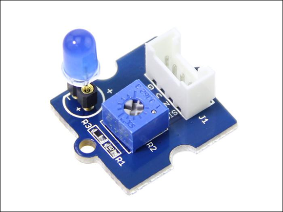
FIGURE 1-4: The Grove blue LED.
For more on Grove connectors, see the next chapter.
For a number of you readers, this will be the first time you've ever assembled a physical computer-based project. The following step-by-step procedure makes the process easy:
- Align the Pi2Grover board with the 40-pin GPIO connector on the Raspberry Pi (see Figure 1-5.)

FIGURE 1-5: Aligning the Pi2Grover board with the Raspberry Pi.
Gently push the Pi2Grover board onto the Raspberry Pi GPIO pins, making sure the pins are aligned (see Figure 1-6).
No pins should be showing on either end. Make sure the pins on the Raspberry Pi and on top of the Pi2Grover board are not bent.

FIGURE 1-6: The installed Pi2Grover board.
- Plug one end of the Grove cable into the Grove blue LED board (see Figure 1-7).
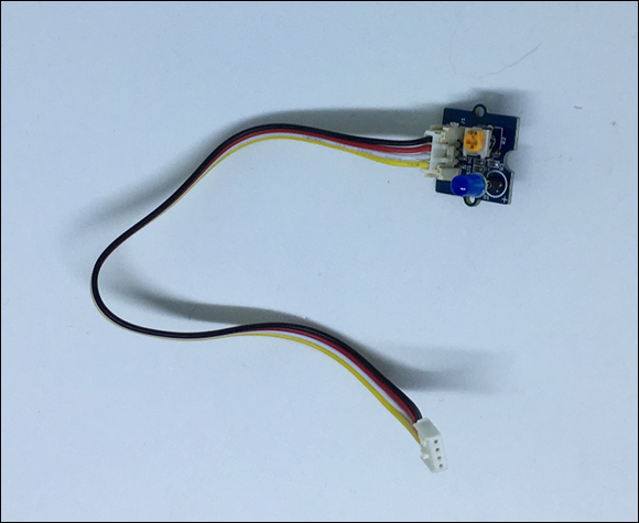
FIGURE 1-7: A Grove cable plugged into the Grove blue LED board.
- If necessary, plug the blue LED into the Grove blue LED board, with the flat side of the LED aligned with the flat side of the outline on the board (see Figure 1-8).
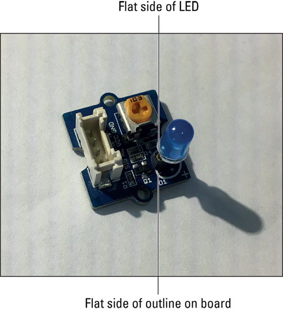
FIGURE 1-8: The LED aligned with the outline on the board.
- Plug the other end of the Grove cable into the slot marked D12/D13 on the Pi2Grover board (see Figure 1-9).
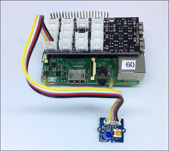
FIGURE 1-9: The completed “Hello World” project.
We've finished assembling the hardware. Now it’s time to create the Python software.
Controlling an LED with Python
Now that we have the hardware connected, we can apply power to the Raspberry Pi. If all is well, the Grove blue LED and a blue power LED on the Pi2Grover board will light, the yellow LED on the Raspberry Pi will flash (during bootup), and the red LED on the Raspberry Pi will light (but may then turn off depending on your power supply).
 The Grove blue LED lights when we turn on the Raspberry Pi power because the GPIO pins on the Raspberry Pi power up as inputs. Because the GPIO pin is an input and nothing is driving the GPIO pin (the Grove LED wants an output, not an input to control the LED), the GPIO pin just floats with an undetermined voltage — it's in tri-state (neither a 1 nor a 0, but somewhere in-between). Because of the circuitry on the Pi2Grover board, the input will float towards a 1, so the LED turns on. When you turn your GPIO pin to an output in the code, the LED will turn off.
To get started, follow these steps:
Using your keyboard, open a Terminal window.
If you don’t know how to open and use a Terminal window and the command line on the Raspberry Pi, go to www.raspberrypi.org/documentation/usage/terminal/for an excellent tutorial.- Enter the following Python code into a file using the nano text editor (or an editor of your choice). Save it to the file
HelloWorld.py.from gpiozero import LED
from time import sleep
blue = LED(12)
while True:
blue.on()
print( "LED On")
sleep(1)
blue.off()
print( "LED Off")
sleep(1) For an excellent tutorial on using the nano text editor, visit www.raspberrypi.org/magpi/edit-text/. - Now the big moment. Start your program by running the following on the command line of the Terminal window:
sudo python3 HelloWorld.py
The LED blinks on and off once per second and the following appears on the screen in the Terminal window:
LED On
LED Off
LED On
LED Off
LED On
LED Off
LED On
LED Off
LED On
LED Off
LED On
To stop the program, press Ctrl+C (^C, in geek terms).
The keyword sudo stands for super user do. We use sudo in front of the python3 command because some versions of the Raspberry Pi operating system restrict a regular user's access to certain pins and functions. By using sudo, we're running this command as a super user, which means it will run regardless. In newer versions of the Raspberry Pi OS, you just type python3 HelloWorld.py. If the program doesn't work, go back to sudo python3 HelloWorld.py.
The following statement imports the LED function from the Python gpiozero library:
from gpiozero import LED
Then we import the sleep function from the Python time library:
from time import sleep
Next, we assign an LED on GPIO 12 (remember D12/D13 on the Pi2Grover board?):
blue = LED(12)
Now we start the loop that will go forever:
while True:
Turn on the LED:
blue.on()
print( "LED On")
Wait for one second to go by:
sleep(1)
Turn off the LED:
blue.off()
print( "LED Off")
sleep(1)
The program then loops forever — until you stop it.
Wow, you've now entered the world of physical computing. Just wait until the next minibook, where you control robots with Python.
But Wait, There's More
Because we have all this hardware set up, we'll do one more project. This time, we use PWM (pulse width modulation) to vary the brightness of the LED.
Pulse-width modulation is a technique in which you vary the amount of time a signal is at 1 versus at 0. Our LED turns on at 1 and off at 0, so if we vary the time the LED is at 1 versus at 0, we can control the brightness as registered by the human eye. This ratio is called the duty cycle, which is shown in Figure 1-10. With a duty cycle of 100 percent, the LED is on 100 percent of the time, and with a duty cycle of 0 percent, it's off all the time. Varying the time the signal is on changes the apparent brightness of the LED. The LED is switched on and off at a default frequency of 100 times per second (Hz), but you can change the frequency.

FIGURE 1-10: Duty cycles.
Enter the following Python code into nano and save it as HelloWorld2.py. Note the PWMLED(12) function, which connects the LED on GPIO pin 12 to the PWM software:
from gpiozero import PWMLED
from time import sleep

led = PWMLED(12)

while True:
    led.value = 0  # off
    sleep(1)
    led.value = 0.5  # half brightness
    sleep(1)
    led.value = 1  # full brightness
    sleep(1)
Run the code, and the brightness will change every second:
sudo python3 HelloWorld2.py
And use the following code to see a smooth continuous brightening and darkening of the LED:
from gpiozero import PWMLED
from signal import pause
led = PWMLED(12)
led.pulse()
pause()
Boy, you accomplished a lot in this chapter. You have now started to see the possibilities of physical computing. And you have a blue LED!