
Chapter 15
Understanding Circuits and Soldering
In This Chapter
![]() Discovering what a circuit is
Discovering what a circuit is
![]() Getting familiar with GPIO
Getting familiar with GPIO
![]() Coming to grips with a soldering iron
Coming to grips with a soldering iron
![]() Looking at ready-made add-on boards
Looking at ready-made add-on boards
Part V of this book deals with what is known as physical computing, making your program reach out beyond the confines of keyboard and screen, and into the physical world. You discover how to use your Python programming skills to sense what is happening in the outside world and to control lights, motors, and in fact anything else that uses electricity. However, before you can do this safely, without risking damage to you or your Pi, you need to look at a little bit of background electrical theory, so you have a foundation to build on.
In this chapter, we show you the relevant concepts that allow you to understand why the projects look like they do and what you should avoid doing. Next we introduce you to the concept of GPIO connections, explain what they are, and look at why they are included in the Raspberry Pi computer. We also discuss how you can use them.
Although you can make the first project in Chapter 16 without soldering, in order to make most things in electronics, you have to be able to use a soldering iron. We show you how to go about this and discuss safety concerns. Finally, although all the projects in this book can be made without them, we introduce you to the concept of ready-made add-on boards because they make building stuff simpler.
Discovering What a Circuit Is
The first thing you have to understand is that a circuit is something where electricity can flow; it is a path, or a conduit. It is continuous; that is, it’s a loop with no dead ends. If you have a dead end, you don’t have a circuit. Electricity has to be able to flow. So let’s be more specific in what we mean by electricity. There are two aspects of electricity: current and voltage.
Current is what actually flows. Voltage is what forces the current round a circuit. Voltage can’t flow and current doesn’t exist in the absence of a voltage. However, voltage can exist in the absence of current. You’ve no doubt felt the effects of static electricity, which is the build-up of voltage that occurs when insulators (materials that don’t normally conduct electricity) are rubbed together.
It’s kind of like how rubbing a balloon on wool can make the hairs on the back of your hand stand up. You can feel it, but only because you feel your hairs being lifted. You aren’t feeling the electricity itself. You only feel static electricity when it stops being static and a current flows. At a very high voltage, a little current can hurt a lot. You’ve probably felt the static discharge shock of touching a metal object after walking over a nylon carpet.
Understanding the nature of electricity
So what is electric current? It is a flow of electrons past a point, just like a flow of cars past a motorway sign. With electric circuits, we measure current in amps. One amp of current is about 6.24×10¹⁸ electrons per second passing a point, or 624 followed by 16 zeros. That’s a big number and fortunately we don’t have to count all of those zeroes. The bigger the voltage, the more current is forced through a circuit, but circuits have a property that resists the flow of current. We call this the resistance of a circuit. This resistance depends on the materials the circuit is made from and is measured in a unit called ohms. So because we know how to define an amp in terms of electron flow, we can define these other two properties in terms of an amp:
One volt is the voltage you need to drive one amp through a circuit with a resistance of one ohm.
You can get a long way in electronics by just knowing that single fact. In fact, that definition is contained in what is known as Ohm’s law:
Volts = Amps × Ohms
However, it would be too easy to just use that as a formula. People would understand it straight off and that would never do! You have to build up a mystique. Imagine how you would feel about a doctor if he actually told you in plain English what was wrong with you? No, it needs to be dressed up so not everyone can understand it. Ohm’s law becomes
E = I × R
where E is the electromotive force measured in Volts, I is the current measured in amps, and R is the resistance measured in ohms.
This is the formula you see in books and all over the Internet, but remember — it’s just
voltage = current × resistance
Connecting things to the Raspberry Pi involves juggling voltage and current, and often you need to use a resistor to limit the current a voltage pushes through a device in a circuit. Using Ohm’s law is the simple way to work out what you need. In Chapter 17, we show you how to use this to make sure you drive light-emitting diodes (LEDs) correctly.
Resistance is not the only thing we can calculate. If we know two of the quantities in a circuit, we can calculate the other one. We do this by rearranging this simple formula to find any one of the quantities if we know the other two. We like the Ohm’s law triangle, which gives the three formulas in one go:

When scientists were first discovering electricity, they knew that it flowed from one terminal to the other. They said the flow was from the positive to the negative, but which was which? Experiments with making a current flow through a solution of water and copper sulphate showed that copper was dissolved from one wire and deposited on the other. So they quite reasonably assumed that the metal was flowing with the flow of electricity and named the dissolving wire an anode or positive and the wire receiving the metal the cathode or negative. They were wrong: The electrons that constitute the current actually flow the other way. However, this notion became so entrenched that today we still use it. We call it conventional current and it flows from the positive to the negative.
In a way, it doesn’t matter which direction we think of it as flowing. It’s the fact that it is flowing that is important, and we use the terms positive and negative so we know what way round it is flowing. Power sources, like batteries and power supplies, are all marked with a positive and negative symbol so you can connect them the correct way. This is known as direct current (DC) because the current only flows in one direction.
The other sort of power supply you can get drives the current round in one direction for a short length of time and then reverses the direction for a short time. This is known as alternating current (AC). A favorite trick that electricians play on their apprentices is to send them to the store to fetch the nonexistent AC battery.
 Switches are used to make or break circuits, so an early name for a switch was a breaker.
Putting theory into practice
To see how this works, consider a simple circuit. To make things a bit clearer and easy to draw, we use symbols to represent components and lines to represent wires that connect the components together, as shown in Figure 15-1.

Figure 15-1: Two circuit symbols representing a switch.
Take a switch. Its symbol is simple (shown in Figure 15-1). There are two types of switches: single throw and double throw. In the single throw, a connection is made or not made through the switch, depending on the switch position. In the double throw switch, a common connector is connected to one or the other switch contact, depending on the switch’s position. That is, when the switch is one way, there is a connection through the switch from one connection to the common connection. When the switch is the other way, the connection is between the other connection and the common connection.
This is called a double-throw switch, or sometimes a changeover switch, because the switch changes over which terminal is connected to the common one. The figures in this section help explain this. However, the important thing to note is that we use the same symbol for a switch, no matter what the physical switch looks like. Figure 15-2 shows just some of the many physical forms a switch can take.
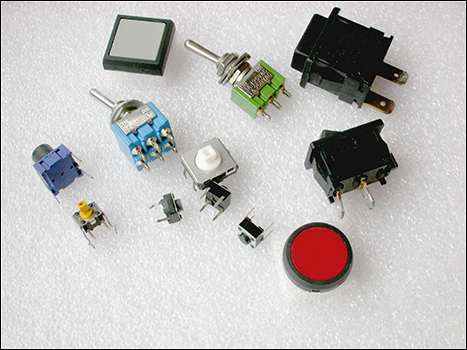
Figure 15-2: Just a few of the many different physical forms a switch can take.
Figure 15-3 shows the symbols for a battery, a small flashlight or torch bulb, and a resistor. Note that there are two symbols for a resistor: one for the U.S and one for Europe. In the U.K., we used to use the U.S. symbol until the late 1960s. Today, both are understood.
The world’s simplest circuit is shown in Figure 15-4. While the switch is open, there is no complete circuit, and so there is no current flow and no lighting of the bulb.

Figure 15-3: Schematic symbols for some components.

Figure 15-4: A schematic of a simple circuit.
However, when the switch is closed as in Figure 15-5, a path for the current to flow along is created and the bulb lights. Note that this diagram has a different symbol for a closed switch than the one used in Figure 15-4. This is so you can more easily see what is going on. Normally, you have to imagine the switch in the open and closed position and visualize the resulting circuit or break in the circuit. We call this a series circuit because all the circuit elements are in a line one after the other, and the same current flows through all elements of the circuit.
So for a circuit like this, there is only one value of current. When the switch is closed, current flows from the positive end of the battery through the switch, through the bulb lighting it up, and finally back into the battery’s negative terminal. Note here the actual electrons are returned to the battery. The battery loses energy because it has to push them round the circuit. The positive and negative terminals of a battery show the direction it will push the current, from the positive to the negative. In this circuit with an incandescent light bulb, the direction of the current doesn’t matter; however, this is rare in electronics. In most circuits, the current must be sent round the circuit in the right direction.

Figure 15-5: A schematic of a circuit with switch closed.
Communicating a circuit to others
You should use circuit symbols in schematics because they’re a universal language and make it easy to see what is going on. Many people waste their time using diagrams that show the physical appearance of components, wires, and their interconnection. Although this might appear at first to be attractive, especially to a beginner, physical layout diagrams like this are almost impossible to follow in all but the most trivial circuits. Despite the initial small hurdle of learning to read the symbols, a schematic is a very much simpler way of defining a circuit. Physical layout diagrams are a dead end for anything more than a trivial circuit and should be avoided.
Some time ago, Mike was visiting Russia and bought his son an electronic construction set. Even though the words were in Russian and incomprehensible to both of them, the diagrams were in the language of schematic and perfectly understandable.
 To show the units of resistance, we can use various symbols. We can say 18 ohms, 18 Ω, or, as we use in this book, 18 R.
Although the units for calculation are volts, amps, and ohms, in practice, 1 amp (A) is a lot of current and it’s more common to talk of milliamps or mA. There are 1,000 mA in 1A. Similarly, 1,000 R is one kilohm or 1 K.
Calculating circuit values
Although the circuit shown in Figure 15-5 is all very well because it describes what’s actually wired up, it’s not useful for calculating anything using Ohm’s law because it shows no resistances. However, each real component has associated with it a resistance. We say it has an equivalent circuit. These are shown in Figure 15-6. All components, even the wires, have some series resistance. In other words, it behaves like it has a resistor in line with the component. Sometimes this is important, and sometimes it is not. The trick is in knowing when to ignore them.

Figure 15-6: A circuit with the effective series resistance values shown.
When resistors are placed in series, or in line with each other, you can find the resistance simply by adding up all the individual resistance values. Figure 15-6 shows our circuit with the series resistance values shown. If we add up all the values around the circuit, you get 18R105 (that’s 18.105 ohms). Note that virtually all the resistance in the circuit comes from the bulb. The series resistance of the switch is negligible, as is the series resistance of the battery. This is not always the case, as you shall see in Chapter 17. So with 18R resistance and 6V, we can calculate that the current through the circuit should be
I = E/R -->
Current = 6/18 = 0.333 Amps or 333mA
Determining how a component needs to be treated
So how do we know the series resistance of a component? Well, it is normally in that component’s data sheet, the document that the manufacturers of all components produce to exactly define the component and its properties. However, it’s not always given as a straightforward value. Take a bulb, for instance. This is normally “rated” as a voltage and a current; that is, we would say that the bulb is 6V at 0.33 amps. If we need to know the equivalent resistance, we use Ohm’s law. Other bulbs, especially big ones, are given a power rating in watts. Current multiplied by voltage is equal to the power in watts.
The other point is that a bulb doesn’t have a constant resistance. We say it’s a nonlinear device; that is, the resistance changes depending on what current is going through it. This is because a bulb is just a coil of wire. As current passes through it, the wire heats up. This causes the resistance to increase, thus limiting the current. An equilibrium point is reached where the temperature reaches a point where the resistance is such that the current is limited to the design value at the design voltage. We use this concept of a nonlinear resistance in Chapter 17 when we come to calculate what resistor we need to use with an LED.
When dealing with units like volts and ohms that include a decimal point, often the point is missed out and the letter of the unit is substituted, so 3.3 volts becomes 3V3, or 4.7K becomes 4K7. This is done to make it clear there is a decimal point that otherwise might be lost in small print.
The series resistance of a battery, or any power supply for that matter, is an important concept in that it limits the current that the battery can deliver. This is all wrapped up in the chemistry of the battery, but its effects can be summed up by a theoretical series resistance. A battery that can deliver a lot of current has a low series resistance. This is sometimes known as the output impedance of the battery.
Now these concepts may seem like they are nothing to do with the Raspberry Pi, but as you shall see in later chapters, these concepts are the ones you need to get the Pi to interact to the world outside the keyboard and screen.
Testing circuits with simulators
Nowadays there are circuit simulators that allow you to test a circuit before you build it. This is a great idea to make sure you are not doing anything silly. However, some simulators have a steep learning curve and others use ideal components instead of real ones. This can give some misleading results with simple circuits, but on the whole they are a very good idea. One simulator written especially for the Raspberry Pi is free. Find out more at www.raspberrypi.org/archives/1917.
Getting Familiar with the GPIO
The Raspberry Pi was made from a BCM2835 system on a chip. Unlike traditional microprocessors, these are designed to be used in an embedded system. An embedded system has a computer inside it, but you don’t use it as a computer — things like mobile phones, media players, and set-top boxes. These chips have a number of connections to them in order for the software in them to control things like push buttons, displays, and getting sound in and out. The BCM2835 has 54 such signals. They are called General Purpose Input/Output pins (GPIO) and they can be controlled by software. Some of these signals are used to build and control the peripheral devices that turn the BCM2835 into a computer, like the SD card reader, the USB, and the Ethernet. The rest are free — that is, not needed to make the Pi — so they are surplus to requirements.
Rather than just ignore them, the designers of the Raspberry Pi have routed some of these surplus GPIO lines out of the chip and to the connector called P1 on the board for us to play with. It’s a bonus. This sets the Pi apart from mainstream computers in this respect. However, they have not routed all the spare pins out to this connector. Some go to other connectors like the camera socket and some are not even connected to anything at all. This is because the BCM2835 is in a ball grid array (BGA) package with connections less than a millimeter apart. So close are they that you can only have enough room for one trace (PCB wire) between the connectors.
This means that to get some of the inner connections out to other components, you have to use a printed circuit board (PCB) that has a number of extra layers of wiring inside the board. You might think the Pi’s board has just a top side and underside, but in fact it is made from several boards sandwiched together to create six layers of wiring.
Even with this many layers, there is not enough room to route out all 54 GPIO signals. Adding more layers would significantly increase the price of the PCB and make our bonus cost something instead of being free. You are no doubt aware that the price point of the Pi is one of its major features. However, over successive hardware revisions, an increasing number of these pins have been brought out to use. There were 17 on the original board, revision 2 saw some rearrangement and another socket bring the total to 21. Finally the Model B+, being revision 3, saw this increase to 28, all on one 40-pin header. This still leaves 8 GPIO pins not routed out or used internally on the board. The Raspberry Pi foundation has announced that the Model B+ represents the last revision of this product. You see exactly where these signals are brought out physically in the next chapter.
Putting the general purpose in GPIO
GPIO pins are called general purpose because we can use them for anything we want under the control of a program. They’re called input/output pins because the software can configure them to be either an input or an output. When a pin is an input, the program can read whether this has a high voltage or a low voltage put on the pin. When the pin is an output, the program can control whether a high voltage or low voltage appears on that pin. In addition, many pins have one or more superpowers, or alternative functions as a secret identity, like so many comic book heroes. These powers are not shared by all pins, but are specialist functions able to do things without software intervention. They are ways to tap directly deep into the computer’s inner workings. When we switch to these functions, they stop being general-purpose pins and do a specific job. For example, one pin can be used to output a continuous stream of high and low voltage levels, that, after they get going, continue without any further intervention from the program. So if you connect that pin to a speaker or amplifier, you can generate a tone that keeps on sounding until you command it to stop.
However, for the moment, just take a look at the GPIO function of these pins.
Understanding what GPIOs do
GPIOs are the gateway to interaction with the outside world and in essence are quite simple.
Figure 15-7 shows the equivalent circuit of a Raspberry Pi GPIO pin when it is configured as an output. You can see it is simply a double throw switch that can be connected between the computer’s power supply of 3V3 or ground (that’s 0V). This is sometimes called the common point or reference, and is the basis of all measurements in a circuit. Basically, it’s the other end of the battery — the negative terminal, if you will. Between this switch and the output is in effect a series resistor, one that is in line with the voltage coming from the Pi. It limits the current you can get through the output pin.

Figure 15-7: A GPIO when used as an output.
On the Pi, the value of this resistor can be changed over a limited range. The default value is 31R, but note that this resistor, by itself, is insufficient to protect the Pi from giving too much current if you connect it to too low a resistance load. So an output pin can switch between only two voltages — 0V and 3V3. These are known as logic levels and they have a number of names: high and low, true and false, zero and one, and even up and down.
Although the logic voltages levels on the Pi are simple, the current that these outputs can supply is more complex, with a current limit of about 16mA. This limit is how much current the Pi should supply into a load, not how much it can supply or will supply. That depends on the resistance of the load connected to the pin. Now I say the limit is about 16mA, but this is a bit of a gray area. This value is considered safe for the Pi to supply, but that is not to say a value of 17mA would be considered dangerous or excessive.
Putting an output pin to practical use
So what can you do with a switched output? Well, you can drive a small current through a load, or you can control another device that can control a bigger current through a load. Put like that, it doesn’t sound exciting, but it’s what physical computing is all about. The load can be a light, a motor, a solenoid (an electromagnetic plunger used to prod or strike things), or anything that uses electricity. As that includes most everything in the modern world, it is safe to say that if it uses electricity, it can be controlled.
Take a look at controlling a light, not the current-heavy light bulb we looked at earlier, but a component known as a light-emitting diode (LED). These can light up from just a tiny bit of current and the 16mA we have available is more than enough. In fact, you’re going to limit the current to less than 10mA by adding a 330R series resistor. Why this value? Well, you see exactly how to calculate this value in Chapter 17.

Figure 15-8: Two ways of driving an LED.
For the moment, just look at the circuit in Figure 15-8. This shows two ways to wire up an LED, or any other load, directly to a GPIO pin. Here we just show the GPIO pin and not the equivalent series resistance of the power source as discussed earlier — in the context of a 330R resistor, 31R is negligible.
The first way to wire it is called current sourcing and is perhaps the way a beginner might think of as natural. When the GPIO pin is set by the program to produce a high voltage (that is, set the switch to connect the 3V3 line to the output pin), current flows from the pin through the LED, through the resistor and to ground, thus completing the circuit, causing current to flow and so lighting up the LED. When the GPIO pin is set by the program to produce a low voltage (that is, set the switch to connect the 0V or ground line to the output pin), no current flows and the LED is not lit. This method is known as current sourcing because the source of the current, the positive connection of the power, is the GPIO pin.
The second way of wiring, also shown in Figure 15-8, is known as current sinking. When the GPIO pin is set by the program to produce a low voltage, the current flows through the LED, through the resistor, and to ground, through the GPIO pin. To turn the LED off, set the output to a high voltage. There’s no way current can flow round the circuit because both ends of the load (LED and resistor) are connected to 3V3, so there is no voltage difference to push the current through the components.
Note in both circuits the position of the resistor and LED can be interchanged — it makes no difference. You might like to think of these two approaches as switching the plus and switching the ground. More of this when you do some real projects in Chapters 17 and 18.
Using GPIOs as inputs
The other basic mode of operation for a GPIO pin is as an input. In this case, you don’t have to worry about the current because when the pin is an input, it has a very high input impedance, or a high value of series resistance. A resistance is a special form of impedance, which, as its name implies, impedes the flow of electricity. There is a bit more to impedance than simple resistance, but at this stage, you can think of them as the same sort of thing. They are both measured in ohms.
Resistance is the property of a material, whereas impedance is the property of a circuit and includes how it behaves with AC as well as DC. So an input pin has a very high impedance. It hardly allows any current to flow through it, so much so that we can connect it directly to either 0V or 3V3 directly without any extra resistors at all. In fact, an input is so high-impedance that if you just leave it unconnected, it picks up very tiny radio waves and other forms of interference and gives random values when you try to read it.
In fact, the human body can act as an antenna when close to or touching a high-impedance input, causing any readings to go wild. This often amazes beginners, who think that they have discovered something mysterious. They haven’t. In fact, the tiny amounts of energy in the radio waves that are all around us are not absorbed by the high-impedance circuits as they would be by low-impedance circuits. A low impedance would cause current to flow, but it would easily absorb all the power, leaving minuscule amounts of voltage. Just the fact that you have a wire carrying AC power (mains) close by is enough for that wire to radiate radio wave interference.
To explain why this is, consider that interference of, say, 2V is enough to override the signal from a chip and cause it to malfunction. With a low resistance, say 1K, in order to develop 2V across, it needs to have a current of 2mA (Ohm’s law) flowing through it. This represents a power (volts×current) of I×V=4mW of interference. However, with a resistance of 1M, you can get 2V across it by only having 2uA flowing through it. This represents a power of 4uW. So a high resistance is much more sensitive to interference because it requires less power from the interfering source to develop the same voltage. Therefore weaker fields produce enough interfering voltage to disrupt a circuit.
This underlines an important thing with inputs: They can’t just be left alone. They must be driven to one voltage state or the other; that is, either 3V3 known as high, or 0V known as low. If you connect an input to the output from some other chip, that’s fine, but if you want to detect whether a switch is made or broken, you have to give the input pin some help. This is normally done with a resistor connected from the input to either the 3V3 or the ground.
When a resistor is used in this way, it’s called a pull-up or pull-down resistor, as shown in Figure 15-9. Of the two arrangements, a pull-up is preferable, mainly because switches are normally on the end of long runs of wire and it is safer to have a ground than a 3V3 voltage on a wire. This is because it tends to cause less damage if you accidentally connect a ground wire to the wrong place rather than to a power wire. This arrangement of pull-up or pull-down resistors is so common that the computer processor in the Pi has them built-in, and there is a software method for connecting or enabling internal pull-up or pull-down resistors. We show you in Chapter 16 how to control this from software.

Figure 15-9: Two ways of using a GPIO as in input.
Learning which end is hot: Coming to grips with a soldering iron
Although you can do some interfacing without resorting to the soldering iron to join components together, to get serious, you’ll have to do some soldering at some stage or the other. This often induces fear and panic in the newcomer, but even a child can solder successfully. In fact, Mike had his first soldering iron at the age of nine and by and large taught himself. Soldering involves two parts, the solder, which is an alloy of two or more metals, and the flux, a chemical cleaning agent. If you are soldering something like a gas pipe, you would apply the flux round the joint, heat the joint up with a blow torch, and apply the rod of solder to the hot joint. The job of the flux when it is heated is to clean the surface and make the solder flow. It does this by breaking down the surface tension on the molten solder. Without it, the solder would clump together in round globs held by the tight surface tension.
Water has surface tension as well, and to reduce that we use soap, which allows the water to wet things. You can’t use soap with solder because it wouldn’t stand the heat, so you need something else. Most fluxes for heavy jobs are made from nasty chemicals like hydrochloric acid, or phosphoric acid. These are too corrosive to be used with electronics, so what is normally used is some sort of rosin flux. Although you can get this in a pot, by far the best thing is to use Multicore solder, where the flux is built into the solder wire as five very thin strands. That way, the right amount of flux is always delivered with whatever amount of solder you use.
We recommend using a good quality 60/40 tin/lead solder alloy, with a diameter of 0.7mm and a built-in rosin-based flux core. Anything else is making life difficult for yourself. We’ve found that solders with self-cleaning fluxes or non-fuming fluxes are harder to work with, as well as being more expensive. Couple the right kind of solder with a good soldering iron, preferably a temperature-controlled one with a fine tip.
It is often said that you can use any old tool to learn on, and then get a good tool when you get good at using it. This is rubbish. As a beginner, you are fighting how to do the job, so you don’t want to be fighting your tools as well. A good iron includes a stand and a place for a sponge. Use a proper soldering iron sponge, a natural one that won’t melt on contact with the iron. Do not use a plastic foam sponge because your iron will go straight through it.
Making a soldered joint
The first thing you should do when making a soldered joint is to make a mechanical joint. For example, if you’re joining two wires together, bend each end into a hook and squeeze together lightly with your pliers.
Wipe the tip of the iron on a damp sponge and melt just a spot of solder on the tip. This wets the tip and allows good thermal contact to take place between the tip and the work. Then apply the iron, solder, and wires all together. The secret is then to look at the joint and the solder closely and how it sits. Remove the solder, but keep the iron on the joint until you see the solder flow around the joint and see it seep into the cracks. Only then is the joint hot enough for you to withdraw your iron. It is a quick process and needs a bit of practice.
Many beginners make the mistake of putting too much solder on a joint. Try to use as little solder as possible. A joint is rarely bad because of too little solder, but it’s often bad because of too much. When you are done, you see a small amount of black flux residue around the iron tip. Wipe that away on a damp sponge before returning the iron to its stand. Do not move the joint as the solder sets. A good quality iron is ready immediately for the next joint. A poor iron needs a few seconds to come up to temperature.
Using some sort of fume extractor when soldering is a good idea. A simple fan works to guide the curl of smoke from the iron away from your face. Air currents from the warmth of your body tend to attract the flux. Try not to breathe it in. This is more important as you spend a long time (hours at a time) with a soldering iron in your hand. The fumes are from the flux in the solder; they are not lead fumes.
Although Chapter 16 contains a project that can be made without the use of a soldering iron, such projects are few and far between. The last two chapters of this Part contain projects for which you definitely need to be able to solder.
Looking at Ready-Made Add-On Boards
Many ready-made interface boards are available for the Raspberry Pi. These are designed to make things easier for you to do by building part of the circuits for you. They range from simply providing easier access to the GPIO pins, to including small sub circuits, to giving the Pi more inputs and outputs, or to performing special functions not available on the Pi directly, like being able to control the brightness of many LEDs. You can always incorporate these sub-circuits into your projects when you need them, but these boards provide a shortcut to some projects by building them for you.
However, note that they are not essential and can be an expensive way of doing a project, mainly because they often contain more capabilities than you actually need for any one project. If you want to break up your project after you have finished it, you get value from these boards, but if you want to keep your projects and plug them in at any time to show others, you’re better off just building what you need. Dedicating a board to a project is an expensive way of doing things. All the projects in later chapters of this book are self-contained and do not require any third-party boards. However, some offer convenience that might be attractive to some people. New boards are constantly being developed and produced. In the next sections, we look at a few.
The Gert board
The Gert board is the granddaddy of expansion boards. It is the closest thing there is to an official Raspberry Pi interface because it’s designed by Gert van Loo, one of the Pi’s design team. It is not a Pi Foundation product. It is a compressive collection of interfaces, including an Arduino-like processor. The Arduino is a standalone controller very popular with artists and engineers alike, it is superficially like a Raspberry Pi but is fundamentally a very different beast. It’s better than the Pi at doing things that require very quick responses and accurate timing, but it has no display and can only be programmed in C++. The Pi and the Arduino can work quite well together and so Gert has included one of these processors on his board. The board is designed for education, to give a flavor of different types of interfacing techniques. Basically, it’s a ready-built board you simply plug into the Pi. Its features are
- Twelve I/O ports buffered through 74HC244, each with an LED
- Three push buttons
- MCP4802: Two channel 8-bit D/A converter
- ULN2803A: Six open collector channels up to 50V ~80ma/channel
- ATmega328P: Atmel®AVR® 8-bit microcontroller (Arduino)
- L6203: 48V 4A motor controller
- 780xx 3V3 low drop-out voltage regulator
It also contains the printed circuit board and the headers, jumpers, straps, flat cable, and sockets to connect to the Pi. It would take a whole book to describe what all these features are and how to use them.
It’s very improbable that any one project would need all these features and it’s probably too advanced for the average beginner. But as you begin to explore this subject beyond what we can cover in this book, you might want to look at it.
The best thing about the Gert is that the manuals are downloadable, so you can see in advance what you are letting yourself in for. You can read all about it and find the manuals’ download links at www.raspberrypi.org/archives/1734.
Pi Face
The Pi Face board is designed by a team at the School of Computing Science at the University of Manchester (U.K.) and is aimed at the education market. It is roughly the same price as the Gert board, but comes ready-assembled. It is much less ambitious in scope but contains a good mix of things you would actually need for many simple projects. These include onboard LEDs and push-button switches for simple interaction along with two relays (physical switches moved by an electromagnet) for switching large currents. There are eight protected inputs and eight buffered outputs and the whole thing has screw connection access to connect it to the outside world. You can download a comprehensive list of documents and examples from Google Documents at https://github.com/piface and follow some of the new projects using the board from www.raspberrypi.org/archives/tag/pi-face. If you’re curious about doing projects using Pi Face, check out the book Raspberry Pi Projects by Dr. Andrew Robinson (published by Wiley).
Other boards
There are many other boards from small start-up manufacturers as well as web-based projects for you to build. You can find a good starting point for information on many of these at http://elinux.org/RPi_Expansion_Boards.
Tipping your HAT
There is a standard way of attaching boards to the Raspberry Pi known as a HAT board. HAT stands for Hardware Attached on Top, and is applicable only to the model B+ of the Raspberry Pi. This board has to meet certian criteria to qualify it as being a HAT. One of which is that it has to have a small read-only memory chip on it to allow the Raspberry Pi to know what GPIO pins are being used so that they are configured during boot-up, load any required drivers, and prevent any possible pin usage conflicts. Read more about HATs at www.raspberrypi.org/introducing-raspberry-pi-hats/.