
CHAPTER 3
Microphone Types
A microphone measures variations in air pressure and transduces soundwaves from acoustic energy to mechanical energy to electrical energy. Ideally, the signal a microphone produces should replicate the waveforms entering the mic as faithfully as possible, so that when a loudspeaker converts the signal back to acoustic energy, listeners hear a reasonably accurate representation of the sound source.
The Behavior of a Pure Diaphragm
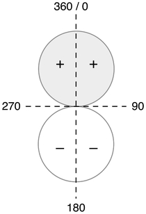
Figure 3.1 Bi-directional pickup pattern of a freely suspended diaphragm.
If a thin plate, or diaphragm, is suspended between two points in a way that exposes both the front and the back to soundwaves, it responds to any difference, or gradient, in air pressure between the two sides. For example, when soundwaves arrive at the front, they exert more pressure on the plate than exists behind it, and this difference causes the diaphragm to flex towards the rear (the opposite happens when soundwaves strike the back). But if soundwaves arrive at the edge, the pressure on the front and back remains identical, and this prevents the diaphragm from moving. Hence, pressure differences/gradients drive the diaphragm, and as shown in Figure 3.1, a freely suspended pressure-gradient transducer naturally produces a bi-directional or figure-8 pickup pattern; that is, it responds equally to sound arriving at the front or the back (0 and 180 degrees) but does not react to sound approaching from the sides at 90 and 270 degrees (the “null” areas). When manufacturers enclose diaphragms, they place these thin plates in the sorts of specialized environments (capsules) that produce the pickup patterns commonly used today.
Condenser Microphones
Condensers operate electrostatically. The capsule that turns mechanical vibration into electrical signal consists of a movable diaphragm and a fixed backplate, which form the two electrodes of a capacitor (previously called a condenser; hence, the name) that has been given a constant charge of DC voltage by an external power source (often supplied from a pre-amp and called phantom power). As soundwaves strike the diaphragm, the distance between the two surfaces changes, and this movement causes the charge-carrying ability (capacitance) of the structure to fluctuate around its fixed value. The resulting variation in voltage creates an electrical current that corresponds to the acoustic soundwave. A vacuum tube (valve) or transistor then boosts the current to ready the signal for post-microphone amplification through an external pre-amp.
Condensers employ either a pressure or a pressure-gradient principle of operation.
Pressure Transducer (Omnidirectional Polar Pattern)
In pressure transducers, microphone designers clamp a single circular diaphragm inside a completely enclosed casing so that they expose only the front face to the sound field. Soundwaves arriving from all directions exert equal force on the diaphragm, and because the diaphragm responds identically to every pressure fluctuation on its surface, these mics exhibit a non-directional, that is, an omnidirectional (360°), response pattern (see Figure 3.2).

Figure 3.2 Omnidirectional pickup pattern.
Manufacturers often use polyethylene for the diaphragm and thinly coat one side with a metal, such as gold. Small holes, evenly distributed across the backplate, dampen the diaphragm’s motion by capturing air as the diaphragm flexes in one direction or the other (see Figure 3.3). A narrow tube connects the interior chamber to the exterior so that the internal and external air pressure remain equal under any atmospheric condition.
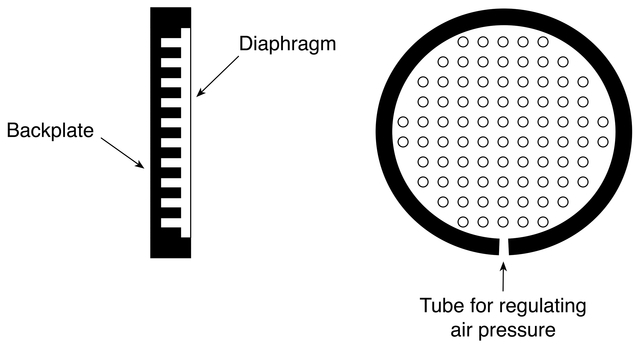
Figure 3.3 Diaphragm and backplate of a pressure transducer.
For use in the free or direct field, omnis can be designed to exhibit a fairly flat frequency response, as the mic mainly picks up direct sound (which has not lost high-frequency content). When recordists use omnis in the diffuse or reverberant sound field, however, the air in the room, as well as the various surfaces the soundwaves strike, absorb some of the higher frequencies. Manufacturers compensate for this loss by altering the design of free-field omnis to make the capsule more sensitive to higher frequencies, so that less of the high-frequency detail is lost.
Pressure-Gradient Transducer (Directional Polar Pattern—Figure-8/Bi-directional; Cardioid and Its Derivatives, Supercardioid and Hypercardioid)
As discussed above, a single diaphragm suspended between two points operates on a pressure-gradient principle and naturally exhibits a bi-directional or figure-8 pickup pattern. However, by combining this pickup pattern with that of an omnidirectional pressure transducer, microphone designers can create unidirectional patterns. Many years ago, researchers realized that because the output of an omnidirectional mic is always positive (gray in Figure 3.2), while bi-directional mics have both positive (gray in Figure 3.1) and negative (white in Figure 3.1) lobes, they could place these capsules in a single housing and produce a pattern that rejected sound from the rear. This pattern resembled the shape of a heart, so these mics became known as cardioids.
Within the configuration, each capsule picks up sound arriving from the front (0°) in phase, and when engineers combine the two outputs electrically, the signal doubles (see Figure 3.4). Sound approaching from the sides, however, sets only the diaphragm of the omni capsule in motion, for figure-8 designs do not respond to soundwaves arriving at right angles. Consequently, the omni portion of the mic produces the side signal on its own. At the rear of the mic, the two capsules generate signals of opposite signs (omni, positive; bi-directional, negative), which cancel each other and make any sound approaching from the rear almost inaudible (the extent of the inaudibility depends, of course, on the angle of incidence). When represented in a single diagram, one can easily see both the summed output of the positive signals at the front of the mic and the cancellation at the rear (see Figure 3.5).
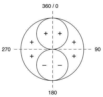
Figure 3.4 Bi-directional and omnidirectional patterns combined.
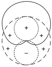
Figure 3.5 The three patterns superimposed (long dash = omnidirectional, short dash = bidirectional, and solid line = cardioid).
Although the first cardioid microphones contained two separate capsules within them, today’s cardioids use principles of acoustic delay to achieve the same result from a single capsule. Manufacturers now place a delay network (also called a labyrinth) behind the diaphragm, and this altered path increases the time it takes for soundwaves to reach the back of the diaphragm; that is, external openings and internal passages in the housing force waves approaching from the rear to reach both the back and the front of the diaphragm at the same time, so that the waves cancel each other. Figure 3.6 shows a simple device, with a single side-entry slot, but designers achieve the desired delay in a number ways: multiple slots in the housing, plates with slots and holes, acoustic resistance (foam, for example), or a combination of methods.
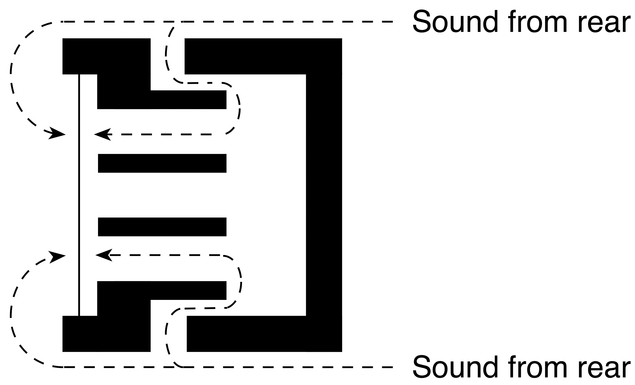
Figure 3.6 Acoustic delay in a cardioid capsule.
Thus, by introducing the correct amount of delay, capsules can attenuate soundwaves arriving from the rear. Moreover, manufacturers design unidirectional microphones to accept soundwaves from wider or narrower angles. Cardioids generally have a pickup or acceptance angle of about 131°, but this can be narrowed to 115° (supercardioid) and 105° (hypercardioid) (see Figure 3.7).
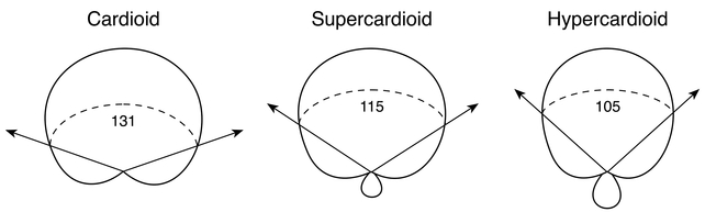
Figure 3.7 Acceptance angles of cardioid capsules.
Outside these acceptance angles, the ratio of direct to incidental sound changes enough for a noticeable loss of uniform response to occur (this change does not begin to become apparent until attenuation reaches about 3.0 dB, and microphone designers generally define an acceptance angle by the arc over which the sensitivity of a mic does not fall by more than 3.0 dB). Hence, a mic’s response remains virtually identical within its angle of acceptance, and recordists should locate sources within the pickup angle if they wish to reproduce the sounds as a sonically homogeneous unit without noticeable degradation in tone color. As shown in Figure 3.7, cardioid microphones have the widest pickup arc among the three common unidirectional patterns. Bi-directional mics have a smaller acceptance angle of 90°.
Manufacturers also produce pressure-gradient electrostatic transducers with two diaphragms. In these double capacitors, each side of the device has a cardioid pattern, and by supplying voltages to the diaphragms independently, designers can achieve various response patterns in the same microphone (see Figure 3.8).

Figure 3.8 Dual diaphragm capsule and the patterns that result from applying voltage independently to each side.
Dynamic and Ribbon Microphones
Dynamic and ribbon mics operate on an electromagnetic principle in which some form of electrically conductive metal moves within a magnetic field to generate electrical current.
In dynamic mics, a light diaphragm connects to a finely wrapped coil of wire suspended in a magnetic field (see Figure 3.9). When soundwaves hit the face of the diaphragm, the attached coil begins to move within the magnetic field. This induces an electrical current proportional to the displacement velocity of the diaphragm (the greater the speed of motion, the greater the current); thus, dynamic mics are also called velocity or moving-coil microphones (these mics usually have a cardioid pattern).

Figure 3.9 Dynamic microphone capsule.
Ribbon mics also operate on the principle of electromagnetic induction, but they produce their natural bi-directional pattern by suspending a diaphragm, consisting of an extremely thin strip of corrugated aluminum (the ribbon), in a strong magnetic field so that both sides engage with the sound source (see Figure 3.10).
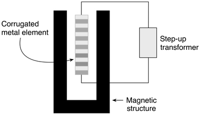
Figure 3.10 Ribbon microphone capsule.
Like dynamic mics, they induce an electrical current proportional to the velocity of displacement. The diaphragm, however, is narrow and short, with extremely low mass. This allows it to respond to the subtlest variations in sound pressure, but the lower conversion efficiencies characteristic of the design prevent the capsule from producing a strong current. Consequently, ribbon mics require considerable amplification before recordists can use the signal in an audio chain (engineers need pre-amps with a great deal of clean gain, as the self-noise of traditional ribbons tends to be well over 20.0 dB). However, a number of manufacturers now produce “active” ribbon mics that have much greater output than the older “passive” designs.