
CHAPTER 5
Stereo Microphone Techniques
Phase integrity obviously bears directly on recording in stereo, and over the decades audio engineers have developed a number of successful strategies for producing realistic stereo images, some of which use principles of time lag to achieve the desired effect.
Stereo miking allows engineers to replicate the way listeners hear individual instruments or ensembles in concert and recital halls, and recordists often employ just two or three microphones to capture the soundwaves emitted by the instrument/ensemble. When reproduced on a stereo playback system, the transduced sound energy generates phantom images at various points between the two loudspeakers. These images simulate the locations of the instrument(s) on the original sound stage and create the illusion of space.
Listeners use two cues, intensity (measured in terms of sound pressure level) and time of arrival, to locate the origin of sounds on a horizontal plane in front of them. Sounds which either arrive first or are stronger provide directional information for listeners, and recordists rely on time and level differences to simulate the sense of spaciousness audiences experience at a “live” event.
In stereo playback systems, listeners hear just two sources of sound, one left and one right, and the phantom images people perceive between the loudspeakers create the illusion of a stereo panorama. The optimum angle for stereo perception is 30° from an imaginary center line to each loudspeaker, and this arrangement places both the listener and the speakers at the corners of an equilateral triangle (see Figure 5.1). When the playback system feeds an identical signal to the loudspeakers, the same amount of sound energy radiates from each one, and the listener perceives the sound not as coming from the individual speakers but from a point equidistant between them (the phantom image). Thus, in this physical layout, no intensity (sound pressure level) or time-of-arrival differences exist at the listening position.
Fortunately, psychoacoustic researchers have established the range of level and time discrepancies required for listeners to perceive sounds as coming from various points along the horizontal plane between left and right loudspeakers. If no level or time differences exist, the hearer localizes the sound source at 0° (as noted above and shown in Figure 5.1), but if recordists want the listener to locate the source somewhere between 0° and 30°, they would have to introduce variations in level or time (or both) between the left and right channels. A difference of 15.0 to 20.0 dB or a delay of about 1.5 ms causes the phantom image to shift all the way to one of the speakers, while smaller variations localize images at specific points along the horizontal plane (see Figure 5.2).
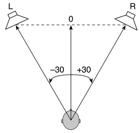
Figure 5.1 Optimum position for listening to stereo playback.

Figure 5.2 Phantom image in stereo playback.
Stereo miking uses the same principles of level and time-of-arrival differences to generate phantom images that simulate what a listener, seated in an ideal location, hears at a “live” event. But, of course, if an engineer wishes to localize instruments appropriately along the plane from left to right, the sound sources must fall within the acceptance angle of the pair of microphones, for if the outer instruments lie beyond the pickup angle, the sound sources will not be localized properly on stereo playback.
Coincident Pairs
By placing two microphones as closely together as possible, audio engineers can virtually eliminate time lags between the mics so that they achieve stereo imaging exclusively through level differences. Such configurations, called coincident pairs, align the diaphragms of the microphones vertically above one another, and this enables the mics to “hear” sound sources along a horizontal plane as if their diaphragms were in the same place. Three manifestations of this concept have become popular among recordists, X-Y, Blumlein, and mid-side.
X-Y
In an X-Y configuration, recordists generally use a matched pair of directional microphones (normally cardioid) and position them symmetrically around an imaginary center line, one mic angled to the left side of the ensemble and the other to the right (see Figure 5.3).

Figure 5.3 X-Y coincident pair of microphones.
Because directional mics exhibit the greatest sensitivity to sounds arriving on-axis and become progressively less sensitive to off-axis sounds, they produce a significantly higher level of signal from sound sources directly in front of them and lower level signals from sources in other locations. When engineers place two cardioids in the way shown in Figure 5.3, each microphone generates the same amount of signal for instruments in the center of the ensemble. On playback, the identical energy radiating from the two loudspeakers produces a phantom image midway between the speakers. But instruments situated some distance from the center will be more on-axis for one mic than the other. When, for example, a performer stands closer to the right-facing microphone, the right mic generates more signal than the left for that instrument. On playback, a higher level radiates from the right loudspeaker of the stereo system than the left, so that the instrument appears off-center to the right, the location of the musician in the original sound stage.
The X-Y configuration produces a strong sense of lateral spread across the stereo sound stage, with a high degree of phase integrity. Although an angle of 90° between the mics remains common, recordists actually place them anywhere from 80° to 130°. The width of the ensemble generally determines the placement, for larger angles between the axes of the microphones create not only wider recording angles but also broader stereo images during playback. Typically, recordists place coincident pairs back from the ensemble about half the width of the sound stage to capture the performers from more of a reverberant perspective.
Audio engineers also use omnidirectional mics in X-Y configurations, and recordists find that a 60° to 90° angle produces a clear central image with a sense of stereo space. Omni pairs have the advantage of maintaining a relatively stable image even when a soloist moves from side to side.
Blumlein
In the 1930s, the British inventor, Alan Blumlein, developed the coincident technique which bears his name. For this array, Blumlein used two bi-directional microphones set at an angle of 90°, so that the axis of maximum sensitivity in one of the mics aligned directly with the axis of least sensitivity in the other (see Figure 5.4). This makes each microphone relatively insensitive to sounds coming from the opposite direction, and the arrangement produces considerable separation between the signals.

Figure 5.4 Blumlein configuration for stereo miking.
On playback, sound arriving at the 0° axis of the pair creates a strong phantom image midway between the loudspeakers (primarily because sounds located centrally between the pair of microphones are actually off-axis by the same amount for each mic). But when engineers place sound sources to the right or left of the 0° axis, the output of one mic increases and the other decreases. At a 45° angle of incidence, either the right or the left microphone reaches its maximum output, while the other remains at zero (for the sound arrives at the null of this mic). Consequently, the varying degrees of level differences between the microphones precisely track the angles of sound arrival. During playback, listeners hear what some people describe as the most accurate representation of the original sound stage.
In many recording situations, the rear lobes of a Blumlein pair face the ambient space of the hall, and when engineers position the mics within the critical distance, they can achieve an appropriate balance between direct and reverberant sound. However, in a hall with poor acoustics, the pair also captures the unfavorable nature of the room. One other disadvantage of the Blumlein technique concerns side reflections. Since both the positive and the negative lobes of the mics pick up lateral reflections, phase cancellations between the two may result in a “hollow” sound quality for listeners.
Mid-Side (M/S)
This technique, developed in the 1950s by Holger Lauridsen of Danish State Radio, uses two different polar patterns to produce a stereo image. A cardioid mic pointing directly at the center of an ensemble picks up the middle of the group (M), while a bi-directional microphone, pointing laterally with its null at the 0° axis of the cardioid, captures the sides (S) of the ensemble (see Figure 5.5).

Figure 5.5 Mid-side technique.
Engineers must process the signals generated by the microphones to produce left and right channels suitable for normal stereo listening. When summed, the superimposed images of the array shown in Figure 5.5 create two polar patterns, one oriented to the left and the other to the right (see Figure 5.6).


Figure 5.6 Summing of the mid-side pickup patterns.
The M/S technique allows engineers to manipulate the two signals by electrical/digital means, and this gives them a great deal of flexibility in creating a stereo image. By varying the amount of the mid and side components, they can easily change the width of the stereo sound stage. For example, a larger amount of mid signal narrows the sound stage, whereas more side signal broadens it.
Engineers achieve this variability by using three input channels of a mixer. They send the signal from the mid mic to its own channel, panned center, and the signal from the side microphone to two separate channels, panned left and right respectively, with the phase/polarity of the right channel inverted. By adjusting the controls in the mixer, they can alter the width of the stereo image (see Figure 5.7).
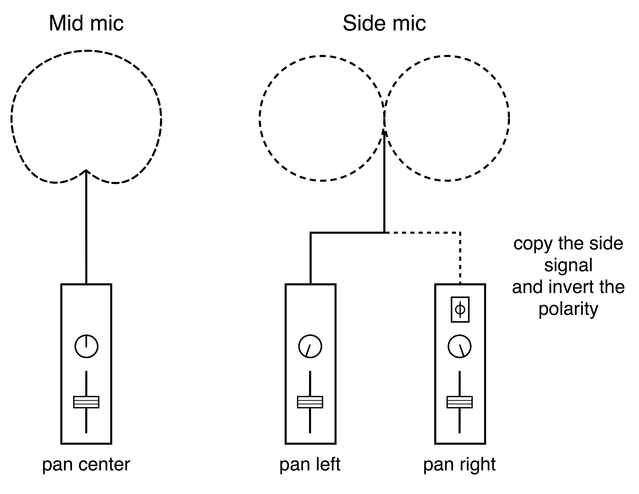
Figure 5.7 Mid-side signal flow in a mixer.
Near-Coincident Arrays
Over the years, audio engineers have developed several strategies for using microphones to mimic human hearing. When recordists separate the capsules of two mics by distances that approximate the spacing between the ears of the average person, they can achieve stereo images through differences in both intensity and time of arrival. This near-coincident technique adds a sense of spaciousness to recordings, for it introduces a small degree of phase interference between the microphones in the higher frequencies (that is, comb filtering above about 1 kHz). The arrays commonly employed today are known by the acronyms ORTF, NOS, DIN, and OSS, and they tend to produce a wider stereo image than the classic X-Y arrangement.
ORTF
Named after the Office de la Radiodiffusion-Télévision Française (French Radio-Television Office), where the technique was developed, ORTF produces a pleasing stereo image, while maintaining adequate phase integrity for monophonic broadcasting. In this array, recordists angle two cardioid microphones at 110°, with the capsules separated by 17 centimeters (6.7 inches). The configuration approximates the average distance from one ear to the other, as well as the typical reception angle (see Figure 5.8).

Figure 5.8 ORTF configuration of stereo microphones.
The use of cardioids provides significant differences in level between the two channels, and at low frequencies, the signals from the mics are virtually phase coherent. At higher frequencies (1 kHz and above), the slight amounts of comb filtering present in the combined signals create what many describe as a sense of “air” or “openness” in the stereo image. A number of recordists feel that this array produces, in the words of Bruce and Jenny Bartlett, “the best overall compromise of localization accuracy, image sharpness, an even balance across the stage, and ambient warmth” (Bartlett 2007: 217–18).
NOS
Audio technicians at the Nederlandse Omroep Stichting (Netherlands Broadcasting Foundation) developed another type of near-coincident array. In this configuration, engineers place two cardioid mics at an angle of 90° and separate the capsules by 30 centimeters (11.8 inches) (see Figure 5.9). This technique relies primarily on differences in level between the microphones, but the wider spacing does produce phase incoherence that begins to become audible at about 250 Hz. This makes the technique less useful for monophonic broadcasting.

Figure 5.9 NOS configuration of stereo microphones.
DIN
Engineers at the Deutsches Institut für Normung (German Institute for Standardization) experimented with another variation of the near-coincident array. They placed two cardioid microphones at an angle of 90° and separated the capsules by 20 centimeters (8 inches) (see Figure 5.10). This technique produces a stereo image through a blend of level and time-of-arrival differences, and recordists find it particularly useful at shorter distances, especially for pianos, small ensembles, or sections of an orchestra.
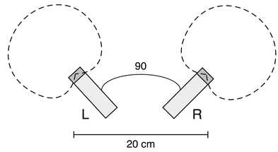
Figure 5.10 DIN configuration of stereo microphones.
OSS (Optimum Stereo Signal; Also Known as the Jecklin Disk)
This system, first proposed by the Swiss radio engineer Jürg Jecklin in 1981, approximates natural binaural (human) hearing by simulating the differences in level, time, and frequency response listeners experience at a “live” event, but in a way that reproduces a realistic stereo image through loudspeakers (note that the binaural approach to stereo recording, a technique which places omnidirectional mic capsules in the ears of a dummy head, only produces a clear stereo image when the two channels are reproduced through headphones).
Jecklin’s original technique (Jecklin 1981) places an omnidirectional microphone on either side of a round disk (28 centimeters or 11 inches in diameter) covered with absorbent material to reduce reflections from the disk (see Figure 5.11). He positioned the capsules 16.5 centimeters (6.5 inches) apart and angled them out from the center of the disk by 20° to replicate the ear positions and soundwave incidence of the average human head. Jecklin later expanded the dimensions of his technique, recommending a 36 centimeter (14.25 inch) spacing between omnidirectional mics mounted on either side of a 35 centimeter (13.75 inch) disk.

Figure 5.11 Jecklin’s OSS technique.
The acoustic baffle between the mics improves the apparent width and clarity of the stereo image. Below 200 Hz, both microphones receive the same signal, and as the frequency rises, diffraction at the edge of the disk increases the effect of separation (around 5.0 dB at 1 kHz and about 10.0 dB at 5 kHz).
The array produces a well-defined stereo image and works best with ensembles that can achieve internal balance (such as occurs in classical music) and in rooms that have nominal or short reverberation times. For the best ratio of direct to reflected sound, recordists often place the array at or within the critical distance in a location that produces an optimal sound quality.
Spaced Microphones
In these arrays, audio engineers do not try to replicate the human head, and they place the microphones much farther apart than with near-coincident pairs. They also situate them well above the sound stage to reduce the differences in distance between the mics and the instruments situated at the front and rear of the ensemble. Recordists tend to favor omnidirectional microphones for these applications, primarily because omnis pick up sound equally well from all angles, which makes them ideal for achieving the desired proportion of direct to reverberant sound. The amount of reverberation recordists wish to capture determines where they locate the mics, and many engineers use the critical distance as a starting point for balancing room reflections and direct sound (the closer the placement the more the direct sound dominates; hence, the microphones pick up less reverberation).
A-B
In this configuration, engineers center two spaced microphones in front of an ensemble to create a stereo image through differences in arrival time. The requirements of the project determine the width of the spacing, but in general, recordists place the microphones an equal distance from the center line of the ensemble, often a third to half the distance from the middle to the outer edge (the greater the spacing, the wider the stereo image; see Figure 5.12).

Figure 5.12 A-B stereo miking.
Sound sources located midway between the mics produce an identical signal in each transducer (because no level or time-of-arrival differences exist), and on playback, listeners hear the phantom images of those sources halfway between the speakers. Sound sources situated to the left or right of this center line are closer to one of the mics than the other, and this prevents the soundwaves from reaching the microphones at the same time. When replicated in playback, the delays shift the phantom images off-center to simulate the location of the sources on the original sound stage. In fact, depending on the width of the sound stage, a microphone spacing of about 61 centimeters (2 feet) allows sounds at the far right and left sides of an ensemble to be reproduced accurately in those locations, because delays of about 1.5 ms, which this spacing creates, cause the images to shift all the way to one speaker or the other. Sound sources partly off-center produce inter-channel delays of less than 1.5 ms, and this allows listeners to perceive phantom images of those sources at various points along the horizontal plane between the loudspeakers.
For large ensembles (such as orchestras), engineers prefer a spacing of 3–4 meters (10–12 feet), but this can provide insufficient coverage for the center of the sound stage, leaving a “hole in the middle,” so to speak. However, a third microphone, or another pair of omnis spaced about 61 centimeters (2 feet) apart, placed midway between the main pair, with the extra signal mixed into both channels, solves this problem.
While widely spaced pairs tend to produce clear center images, the human ear has more difficulty distinguishing off-center stereo images generated solely by differences in arrival time. Thus, in this technique, side images tend to sound unfocused (that is, listeners find them hard to localize), especially since random phase relationships between the two channels can cause comb filtering. This gives the overall sound of a recording a diffuse and blended character, instead of a sharp and focused one, but for many people, these defects create a sense of spaciousness in which concert hall reverberation seems to surround the instruments.
Faulkner Phased Arrays
In 1981, the British recording engineer Tony Faulkner wrote about his technique of spacing two bi-directional microphones 20 centimeters (8 inches) apart directly facing the sound source (Faulkner 1981; see Figure 5.13). The method produces “coherent imaging plus an open feeling” (Borwick 1990: 132), and Faulkner typically placed the mics a distance from the ensemble equal to or greater than the width of the sound stage. Recordists consider this location particularly useful for very reverberant environments, such as large churches, because the microphone pair allows them to obtain clarity at the center of the stereo image, what Faulkner refers to as a dryer sound (Røde 2011: 30:46–31:44), while capturing the natural ambience of the room. The increased distance from the ensemble also permits engineers to set the mics at a lower height than closer locations would allow (perhaps as low as ear level). But when recordists need to place the microphones nearer the ensemble, they sometimes use omnidirectional flanking mics (roughly a meter or 3.3 feet apart) to counter the narrow stereo spread that might result from the use of the spaced pair on its own.

Figure 5.13 Faulkner phased array.
Faulkner then expanded his phased array technique for use with large orchestras. Over the conductor’s head, he places two omnidirectional mics 67 centimeters (26.5 inches) apart, with an ORTF pair of cardioids in the middle, 41 centimeters apart (see Figure 5.14). In this array, the near-coincident pair gives a sense of presence (closeness), while the omnis help create a feeling of ambience around the performers (Røde 2011: 38:55–39:04; Simmons 2016: unpaginated).

Figure 5.14 Expanded Faulkner phased array.
Decca Tree
This technique, originally pioneered by Roy Wallace of Decca Records in 1954, employs three omnidirectional microphones arranged in a triangle. The exact dimensions of the “tree” vary a great deal, but recordists often space the left and right microphones approximately 2 meters (6.5 feet) apart, with the center mic placed about 1.0 to 1.5 meters (39 to 59 inches) in front. In addition, they generally situate the array at or slightly behind and 2 or more meters (6.5 feet) above the conductor’s head (see Figure 5.15).

Figure 5.15 Decca tree.
The relatively close spacing of the left and right mics generates not only sufficient level differences to achieve good stereo imaging on playback but also enough phase information to create an open sound. By capturing a solid central image, the middle microphone eliminates the “hole-in-the-middle” problem. In short, the Decca tree produces a spacious sound with sharp images. Over the years since Roy Wallace first introduced this array, many variations of the technique have been employed. Recordists have altered the distances between the microphones, used cardioid and bi-directional mics, and replaced the center microphone with a coincident pair (often X-Y or M/S), a substitution that provides “articulation” for the stereo image, while generating a sense of “spaciousness” through the outer mics.
References
Bartlett, Bruce and Jenny Bartlett. 2007. Recording Music on Location: Capturing the Live Performance. Boston, MA: Focal Press.
Borwick, John. 1990. Microphones: Technology and Technique. Boston, MA: Focal Press.
Faulkner, Tony. 1981. “A Phased Array.” Hi-Fi News & Record Review 26: 44–6.
Jecklin, Jürg. 1981. “A Different Way to Record Classical Music.” Journal of the Audio Engineering Society 29/5: 329–32.
Røde Microphones. 2011. “Interview with a Legend: Tony Faulkner.” Available at: www.youtube.com/watch?v=8uCcFIyJJ-w.
Simmons, Greg. 2016. “Stereo Masterclass [Interview with Tony Faulkner].” AudioTechnology, 31 May. Available at: www.audiotechnology.com.au/wp/index.php/stereo-masterclass/.