
Optimizing Functional and Quality Requirements According to Stakeholders’ Goals
Azadeh Alebrahim1; Christine Choppy2; Stephan Faßbender1; Maritta Heisel1 1 University of Duisburg-Essen, Essen, Germany
2 University Paris 13 - Sorbonne Paris Cité, LIPN CNRS UMR 7030, Villetaneuse, France
Abstract
High-quality software has to consider various quality issues and different stakeholder goals. Such diverse requirements may be conflicting, and the conflicts may not be visible at first sight. We propose a method to obtain an optimal set of requirements that contains no conflicts and satisfies the stakeholder goals and quality requirements to the largest possible extent. We first capture the stakeholders’ goals and then analyze functional and quality requirements using an extension of the problem frame approach. To obtain an optimal set of requirements, we first determine candidates for requirements interaction. For negatively interacting requirements, we derive alternatives in a systematic way. To prepare for the optimization, we need to assign values to the different requirements. To determine those values, we apply the Analytical Network Process (ANP). Finally, we use existing optimizer tools to obtain a set of requirements that has a maximal value with respect to the previously determined values and that does not contain any conflicting requirements. We illustrate our method with the real-life example of smart metering.
Acknowledgment
This research was partially supported by the German Research Foundation (DFG) under grant number HE3322/4-2 and the EU project Network of Excellence on Engineering Secure Future Internet Software Services and Systems (NESSoS, ICT-2009.1.4 Trustworthy ICT, Grant No. 256980).
Introduction
Nowadays, for almost every software system, various stakeholders with diverse interests exist. These interests give rise to different sets of requirements. The combination of these requirements may lead to interactions among them. But interactions may not only stem from requirements of different stakeholders, but also from different qualities that are desired by the stakeholders. In such a situation it is hard to select those requirements that serve the different stakeholders in an optimal way, even if all requirements are elicited. First of all, it is a necessary quality of a system to be free of unwanted requirements interactions. Hence, some requirements might have to be removed. But removing requirements might have a huge impact on each stakeholder’s perceived quality regarding the expected functionality and qualities, such as performance or security. In order to select the overall optimal set of requirements, one that is free of unwanted interactions, considering the expectations of all stakeholders, one has to discover the interactions, decide whether there are alternatives for problematic requirements, and prioritize and/or valuate requirements with respect to the involved stakeholders.
The analysis of interactions and dependencies among requirements is called requirements interaction management. Robinson et al. (2003) define it as the “set of activities directed towards the discovery, management, and disposition of critical relationships among sets of requirements.” In this chapter, we not only aim at giving a structured method for requirements interaction management, but also at extending it by further steps toward an optimal set of requirements. We not only strive for detecting and documenting interactions, but also for resolving negative interactions in such a way that the resulting requirements are optimal regarding the stakeholders’ expectations.
Our general approach for optimizing functional and quality requirements regarding stakeholder goals (see Figure 4.1) consists of the preparatory phases Understanding the Purpose and Understanding the Problem and the phase Reconciliation. To cover the Reconciliation phase, we propose the QuaRO (Quality Requirements Optimization) method, which is our main contribution for this chapter. An overview of the method is given in Figure 4.1. The first step for reconciliation is to discover the interactions between the requirements (Detection of Interactions in Figure 4.1). Then, we need to generate alternatives for interacting requirements (Generation of Alternatives). For optimization, the requirements need a value to which the optimization can refer. The relations between requirements also need to be valuated. This is achieved in the third step (Valuation of Requirements). Finally, we set up an optimization model that uses the input information from previous steps to compute the optimal set of requirements regarding the optimization goals and the valuation of the requirements (Optimization of Requirements). QuaRO can be integrated into existing software engineering methods.
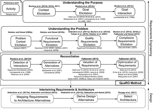
The optimal set of requirements obtained by QuaRO forms the basis of the subsequent steps of software development, in particular architectural design. The phase Intertwining Requirements & Architecture in Figure 4.1 gives an overview of the further steps. Given that architectural decisions may have repercussions on the requirements, requirement descriptions and architectural descriptions have to be considered as intertwining artifacts to be developed concurrently, as proposed by the Twin Peaks model (Nuseibeh, 2001).
Note that in the literature references given above the different steps refer to our own previous work, whereas the literature references given below the different steps refer to related work of other authors. In our previous work regarding detection of interactions (Beckers et al., 2012b), we performed a threat analysis to find interactions among various stakeholder goals regarding privacy. In this chapter, we focus on detecting interactions among security and performance requirements. In another previous work (Faßbender, 2012), we sketched our first ideas to obtain an optimal set of requirements that is compliant and secure.
The remainder of the chapter is organized as follows. In Section 4.1, we introduce the smart grid example, which we use to illustrate the application of the QuaRO method. We present the background on which our method is built in Section 4.2. Section 4.3 is devoted to illustrating the preparatory phases, including understanding the purpose of the system and understanding the problem. We describe the QuaRO method in Sections 4.4–4.7. After detecting interaction candidates among quality requirements in Section 4.4, we generate alternatives for conflicting requirements in Section 4.5. Subsequently, all the requirements and their relations have to be valuated (Section 4.6) in order to provide input for the optimization model we set up in Section 4.7. Related work is discussed in Section 4.8, and conclusions and perspectives are given in Section 4.9.
4.1 Smart Grid
To illustrate the application of the QuaRO method, we use the real-life example of smart grids. As sources for real functional and quality requirements, we consider diverse documents such as “Application Case Study: Smart Grid” and “Smart Grid Concrete Scenario” provided by the industrial partners of the EU project NESSoS,1 the “Protection Profile for the Gateway of a Smart Metering System” (Kreutzmann et al., 2011) provided by the German Federal Office for Information Security,2 “Smart Metering Implementation Program, Overview Document” (Department of Energy and Climate Change, 2011a) and “Smart Metering Implementation Program, Design Requirements” (Department of Energy and Climate Change, 2011b) provided by the UK Office of Gas and Electricity Markets,3 and “D1.2 Report on Regulatory Requirements (Remero et al., 2009b)” and “Requirements of AMI (Advanced Multi-metering Infrastructure”) (Remero et al., 2009a) provided by the EU project OPEN meter.4
4.1.1 Description of smart grids
To use energy in an optimal way, smart grids make it possible to couple the generation, distribution, storage, and consumption of energy. Smart grids use information and communication technology (ICT), which allows for financial, informational, and electrical transactions.
Figure 4.2 shows the simplified context of a smart grid system based on the protection profile (Kreutzmann et al., 2011). We first define the terms specific to the smart grid domain taken from the protection profile:

Gateway represents the central communication unit in a smart metering system. It is responsible for collecting, processing, storing, and communicating meter data.
Meter data refers to meter readings measured by the meter regarding consumption or production of a certain commodity.
Meter represents the device that measures the consumption or production of a certain commodity and sends it to the gateway.
Authorized external entity could be a human or IT unit that communicates with the gateway from outside the gateway boundaries through a Wide Area Network (WAN). The roles defined as external entities that interact with the gateway and the meter are consumer, supplier, gateway operator, gateway administrator, etc. (For the complete list of possible external entities see the protection profile (Kreutzmann et al., 2011)).
WAN (Wide Area Network) provides the communication network that interconnects the gateway with the outside world.
LMN (Local Metrological Network) provides the communication network between the meter and the gateway.
HAN (Home Area Network) provides the communication network between the consumer and the gateway.
LAN (Local Area Network) provides the communication network that interconnects domestic equipment or metrological equipment.5
Consumer refers to the end user or producer of commodities (electricity, gas, water, or heat).
For the smart grid, different quality requirements have to be taken into account. Detailed information about consumers’ energy consumption can reveal privacy-sensitive data about the persons staying in a house. Hence, we are concerned with privacy issues. A smart grid involves a wide range of data that should be treated in a secure way. Additionally, introducing new data interfaces to the grid (smart meters, collectors, and other smart devices) provides new entry points for attackers. Therefore, special attention should be paid to security concerns. The number of smart devices to be managed has a deep impact on the performance of the whole system. This makes performance of smart grids an important issue.
Due to the fact that different stakeholders with diverse and partially contradicting interests are involved in the smart grid, the requirements for the whole system contain conflicts or undesired mutual influences. Therefore, the smart grid is a very good candidate to illustrate our method.
4.1.2 Functional requirements
The use cases given in the documents of the open meter project are divided into three categories: minimum, advanced, and optional. Minimum-use cases are necessary to achieve the goals of the system, whereas advanced-use cases are of high interest, but might not be absolutely required, and optional-use cases provide add-on functions. Because treating all 20 use cases would go beyond the scope of this work, we decided to consider only the use case Meter Reading for Billing. This use case is concerned with gathering, processing, and storing meter readings from smart meters for the billing process. The considered use case belongs to the category minimum.
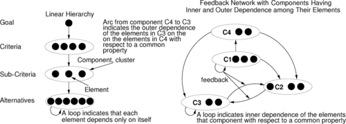
The protection profile (Kreutzmann et al., 2011) states that “the Gateway is responsible for handling Meter Data. It receives the Meter Data from the Meter(s), processes it, stores it and submits it to external parties” (p. 18). Therefore, we define the requirements RQ1-RQ3 to receive, process, and store meter data from smart meters. The requirement RQ4 is concerned with submitting meter data to authorized external entities. The gateway shall also provide meter data for consumers for the purpose of checking the billing consistency (RQ5). Requirements with their descriptions are listed in Table 4.1.
Table 4.1
Requirements for Smart Metering
| Requirement | Description | Related Functional Requirement |
| RQ1 | Smart meter gateway shall receive meter data from smart meters | – |
| RQ2 | Smart meter gateway shall process meter data from smart meters | – |
| RQ3 | Smart meter gateway shall store meter data from smart meters | – |
| RQ4 | Smart meter gateway shall submit processed meter data to authorized external Entities | – |
| RQ5 | The gateway shall provide meter data for consumers for the purpose of checking the billing consistency | – |
| RQ6 | The gateway shall provide the protection of integrity when receiving meter data from a meter via the LMN | RQ1 |
| RQ7 | The gateway shall provide the protection of confidentiality when receiving meter data from a meter via the LMN | RQ1 |
| RQ8 | The gateway shall provide the protection of authenticity when receiving meter data from a meter via the LMN | RQ1 |
| RQ9 | Data shall be protected from unauthorized disclosure while persistently stored in the gateway | RQ3 |
| RQ10 | Integrity of data transferred in the WAN shall be protected | RQ4 |
| RQ11 | Confidentiality of data transferred in the WAN shall be protected | RQ4 |
| RQ12 | Authenticity of data transferred in the WAN shall be protected | RQ4 |
| RQ13 | The gateway shall provide the protection of integrity when transmitting processed meter data locally within the LAN | RQ5 |
| RQ14 | The gateway shall provide the protection of confidentiality when transmitting processed meter data locally within the LAN | RQ5 |
| RQ15 | The gateway shall provide the protection of authenticity when transmitting processed meter data locally within the LAN | RQ5 |
| RQ16 | Data shall be protected from unauthorized disclosure while temporarily stored in the gateway | RQ1 |
| RQ17 | Privacy of the consumer data shall be protected while the data is transferred in and from the smart metering system | RQ1, RQ4, RQ5 |
| RQ18 | The time to retrieve meter data from the smart meter and publish it through WAN shall be less than 5 s (together with RQ20, RQ22, RQ24) | RQ1 |
| RQ19 | The time to retrieve meter data from the smart meter and publish it through HAN shall be less than 10 s (together with RQ21, RQ23, RQ25) | RQ1 |
| RQ20 | The time to retrieve meter data from the smart meter and publish it through WAN shall be less than 5 s (together with RQ18, RQ22, RQ24) | RQ2 |
| RQ21 | The time to retrieve meter data from the smart meter and publish it through HAN shall be less than 10 s (together with RQ19, RQ23, RQ25) | RQ2 |
| RQ22 | The time to retrieve meter data from the smart meter and publish it through WAN shall be less than 5 s (together with RQ18, RQ20, RQ24) | RQ3 |
| RQ23 | The time to retrieve meter data from the smart meter and publish it through HAN shall be less than 10 s (together with RQ19, RQ21, RQ25) | RQ3 |
| RQ24 | The time to retrieve meter data from the smart meter and publish it through WAN shall be less than 5 s (together with RQ18, RQ20, RQ22) | RQ4 |
| RQ25 | The time to retrieve meter data from the smart meter and publish it through HAN shall be less than 10 s (together with RQ19, RQ21, RQ23) | RQ5 |
4.1.3 Security and privacy requirements
To ensure security of meter data, the protection profile (Kreutzmann et al., 2011, pp. 18, 20) demands protection of data from unauthorized disclosure while received from a meter via the LMN (RQ7), while temporarily or persistently stored in the gateway (RQ9, RQ16), while transmitted to the corresponding external entity via the WAN (RQ11), and while transmitted locally within the LAN (RQ14). The gateway shall provide the protection of authenticity and integrity when receiving meter data from a meter via the LMN to verify that the meter data have been sent from an authentic meter and have not been altered during transmission (RQ6, RQ8). The gateway shall provide the protection of authenticity and integrity when sending processed meter data to an external entity, to enable the external entity to verify that the processed meter data have been sent from an authentic gateway and have not been changed during transmission (RQ10, RQ12, RQ13, RQ15). Privacy of the consumer data shall be protected while the data is transferred in and from the smart metering system (RQ17).
4.1.4 Performance requirements
The report “Requirements of AMI” (Remero et al., 2009a, pp. 199-201) demands that the time to retrieve meter data from the smart meter and publish it through WAN shall be less than 5 s. Due to the fact that we decompose the whole functionality from retrieving meter data to publishing it into requirements RQ1-RQ4, we also decompose this performance requirement into requirements RQ18 (complementing RQ1), RQ20 (complementing RQ2), RQ22 (complementing RQ3), and RQ24 (complementing RQ4). The requirements RQ18, RQ20, RQ22, and RQ24 shall be fulfilled in a way that in total they do not need more than 5 s.
Further, the report “Requirements of AMI” states that for the benefit of the consumer, actual meter readings are to be provided to the end consumer device through HAN. It demands that the time to retrieve meter data from the smart meter and publish it through HAN shall be less than 10 s. Similar to the previous requirement, we decompose this requirement into requirements RQ19 (complementing RQ1), RQ21 (complementing RQ2), RQ23 (complementing RQ3), and RQ25 (complementing RQ5). These requirements together shall be fulfilled in less than 10 s.
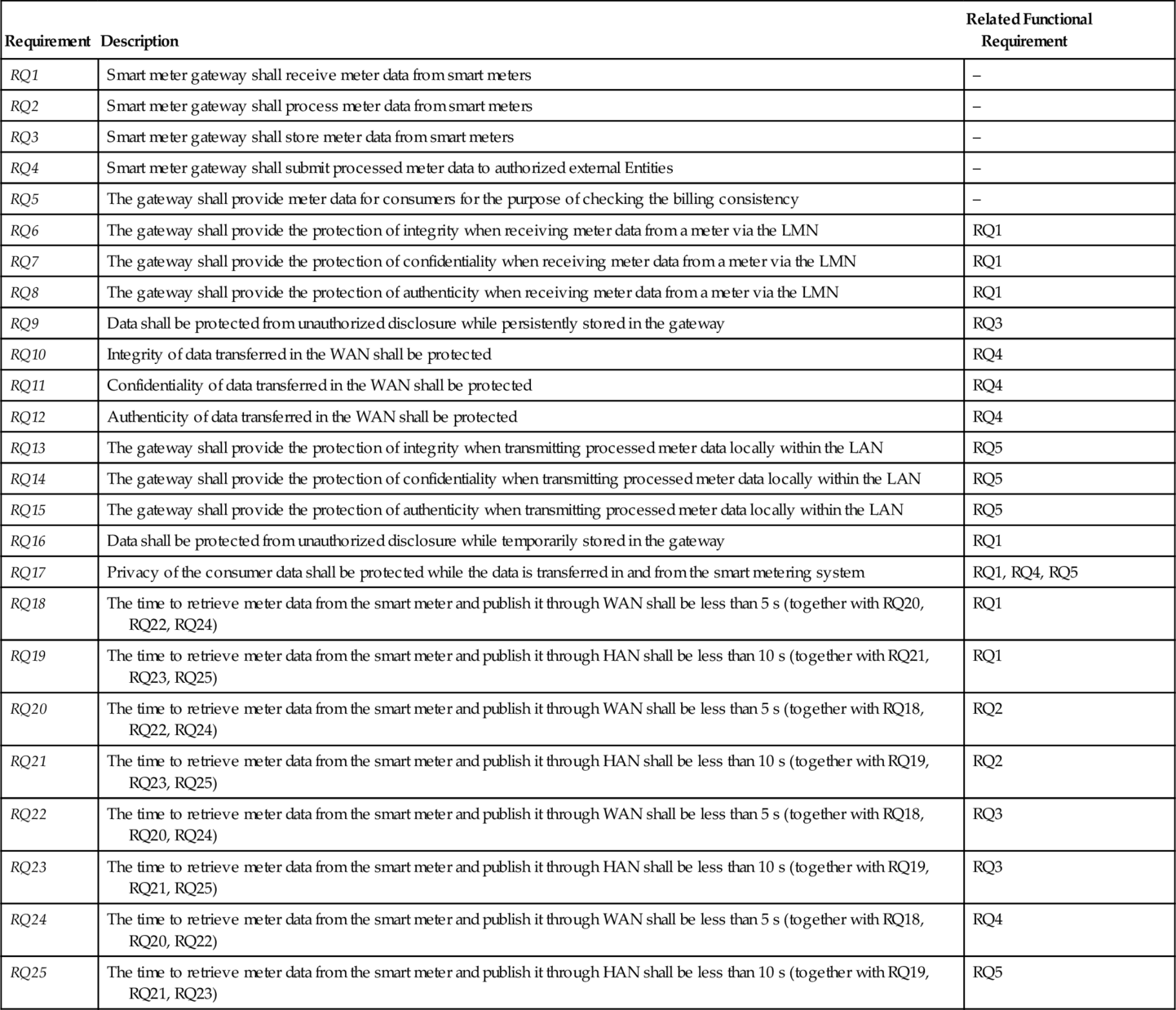
Figure 4.3 shows five quality requirements RQ10, RQ11, RQ12, RQ17, and RQ24 that complement the functional requirement RQ4.
4.2 Background, Concepts, and Notations
This section outlines concepts and terminologies our method relies on. In the preparatory phase Understanding the Purpose, we make use of the goal notation i*, introduced in Section 4.2.1. The problem frames approach and our enhancements described in Section 4.2.2 are used in the preparatory phase Understanding the Problem. Subsequently, we give a brief overview of the analytical network process (ANP), which is used in the Reconciliation phase in the step Valuation of Requirements. Finally, the relevant concepts in the field of optimization to be used in the step Optimization of Requirements of the Reconciliation phase are introduced in Section 4.2.4.
4.2.1 The i* framework
In the i* framework (Yu, 1996, 1997), goal graphs serve to visualize the goals of an actor. Hence, the first element of a goal graph is the actor visualized by the actor boundaries (see Figure 4.5: light gray rectangles with rounded corners). Actor boundaries indicate intentional boundaries of a particular actor. All of the elements within a boundary for an actor are explicitly desired by that actor. For our use case, the consumer, the billing manager, and the grid operator Tesla Inc. are actors. A goal of an actor represents an intentional desire of this actor. The i* framework distinguishes between hard goals, soft goals, and tasks. A hard goal defines a desire for which the satisfaction criteria are clear, but the way of satisfying it is unspecified. Hard goals are visualized as ellipses (see Figure 4.5). An example is the hard goal of Tesla Inc.: “Get Money.” It is satisfied whenever Tesla Inc. receives its money from the consumer but is not specific about the process to get the money. A soft goal is even more underspecified, because for a soft goal no clear satisfaction criteria are known. Soft goals are denoted as clouds (see Figure 4.5). An example is the high-level goal “Performance,” because at this level one cannot give a process for achieving performance nor can one give an overall criterion when a consumer perceives a system as performant. In contrast, a task defines both the criteria for fulfilling the goal and the process to do so. Tasks are denoted as hexagons (see Figure 4.5).
Goals are connected by links. The first kind of link is the contribution link. Contribution links are visualized using arrows with filled arrowheads (see Figure 4.5). A contribution link between a child goal (tail of the arrow) and a parent goal (arrow head) means that the child goal influences the satisfaction of the parent goal. The annotation of the arrow specifies the kind of contribution. A break denotes that the child denies the parent. A make denotes that if the child is satisfied the parent is satisfied, too. An or means that at least one of the children has to be satisfied for the satisfaction of the parent. For an and contribution all children have to be satisfied. Hurts specifies a negative influence, which does not necessarily break the parent goal. Helps is used whenever the child goal has a positive influence but is not necessarily needed to fulfill the parent goal. The second kind of link is the decomposition link. It is used to decompose a goal to more fine-grained parts. A decomposition link is denoted as arrow with a T-head (see Figure 4.5).
4.2.2 Problem-oriented requirements engineering
Problem frames (Jackson, 2001) are a means to describe and classify software development problems. A problem frame represents a class of software problems. A problem frame is described by a frame diagram, which basically consists of domains, interfaces between them, and a requirement.
Domains describe entities in the environment. Michael Jackson distinguishes the domain types biddable domains that are usually people, causal domains that comply with some physical laws, and lexical domains that are data representations. Interfaces connect domains, and they contain shared phenomena. Shared phenomena may be events, operation calls, messages, and the like. They are observable by at least two domains, but controlled by only one domain, as indicated by the name of that domain and “!”. In Figure 4.3 the notation MD!{data} (between MeterData and SubmitMD) means that the phenomenon data is controlled by the domain MeterData and observed by the machine SubmitMD.
When we state a requirement, we want to change something in the world with the software to be developed. Therefore, each requirement constrains at least one domain. Such a constrained domain is the core of any problem description, because it has to be controlled according to the requirements. A requirement may refer to several other domains. The task is to construct a machine (i.e., software) that improves the behavior of the environment (in which it is integrated) in accordance with the requirements.
Requirements analysis with problem frames proceeds as follows: First the environment in which the machine will operate is represented by a context diagram. A context diagram consists of machines, domains, and interfaces. Then, the problem is decomposed into sub-problems, which are represented by problem diagrams. A problem diagram consists of one submachine of the machine given in the context diagram, the relevant domains, the interfaces between these domains, and a requirement.
We represent problem frames using UML class diagrams, extended by a new UML profile (UML4PF) as proposed by Hatebur and Heisel (2010c). Using specialized stereotypes, the UML profile allows us to express the different diagrams occurring in the problem frame approach using UML diagrams. Figure 4.3 illustrates one subproblem expressed as a problem diagram in UML notation in the context of our smart grid example. It describes that smart meter gateway submits meter data to an authorized external entity. The submachine SubmitMD is one part of the smart meter gateway. It sends the MeterData through the causal domain WAN to the biddable domain AuthorizedExternalEntity. The requirement RQ4 constrains the domain WAN. This is expressed by a dependency with the stereotype ![]() constrains
constrains ![]() . It refers to the domains MeterData and AuthorizedExternalEntity as expressed by dependencies with the stereotype
. It refers to the domains MeterData and AuthorizedExternalEntity as expressed by dependencies with the stereotype ![]() refersTo
refersTo ![]() .
.
Requirements analysis based on the classical problem frames does not support analyzing quality requirements. So, we extended it by explicitly taking into account quality requirements, which complement functional requirements (Alebrahim et al., 2011a). Figure 4.3 shows five quality requirements RQ10, RQ11, RQ12, RQ17, and RQ24 that complement the functional requirement RQ4. This is expressed by dependencies from the quality requirements to the functional requirement with the stereotype ![]() complements
complements ![]() . We use a UML profile for dependability (Hatebur and Heisel, 2010c) to annotate problem diagrams with security requirements. For example, we apply the stereotypes
. We use a UML profile for dependability (Hatebur and Heisel, 2010c) to annotate problem diagrams with security requirements. For example, we apply the stereotypes ![]() integrity
integrity ![]() ,
, ![]() confidentiality
confidentiality ![]() , and
, and ![]() authenticity
authenticity ![]() to represent integrity, confidentiality, and authenticity requirements as it is illustrated in Figure 4.3. To annotate privacy requirements, we use the privacy profile (Beckers et al., 2012b) that enables us to use the stereotype
to represent integrity, confidentiality, and authenticity requirements as it is illustrated in Figure 4.3. To annotate privacy requirements, we use the privacy profile (Beckers et al., 2012b) that enables us to use the stereotype ![]() privacyRequirement
privacyRequirement ![]() . To provide support for annotating problem descriptions with performance requirements, we use the UML profile MARTE (Modeling and Analysis of Real-time and Embedded Systems) (UML Revision Task Force, 2011). We annotate each performance requirement with the stereotype
. To provide support for annotating problem descriptions with performance requirements, we use the UML profile MARTE (Modeling and Analysis of Real-time and Embedded Systems) (UML Revision Task Force, 2011). We annotate each performance requirement with the stereotype ![]() gaStep
gaStep ![]() to express a response time requirement. Note that for each type of quality requirement, a new UML profile should be created if not existing. This needs to be done only once.
to express a response time requirement. Note that for each type of quality requirement, a new UML profile should be created if not existing. This needs to be done only once.
As a basis for our QuaRO method, we use the problem frames approach, because it allows us to obtain detailed information from the structure of problem diagrams. Such information is crucial for our proposed approach, because it enables us to perform interaction analysis and optimization, whereas other requirements engineering approaches such as scenario-based approaches and use cases do not contain detailed information for such analyses.
4.2.3 Valuation of requirements
For valuating and comparing alternatives among each other, several methods are known, such as direct scoring (Pomerol and Barba-Romero, 2000), Even Swaps (Mustajoki and Hämäläinen, 2007), win-win negotiating, the analytical hierarchy process (AHP) (Saaty, 2005; Saaty and Ozdemir, 2003) or the ANP (Saaty, 2008a, 2005). They all support decision making (process of selecting a solution among a set of alternatives) by either eliminating alternatives successively or ranking them. For the QuaRO method, we decided to use the ANP (reasons for the decision are discussed in Section 4.6), which will be explained in the following.
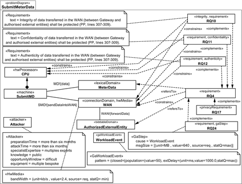
The ANP is a generalization of the more widely known AHP (Saaty, 2008a, 2005). Both rely on goals, criteria, and alternatives. These elements are grouped by clusters, which can be ordered in hierarchies (AHP, ANP) or networks (ANP) (see Figure 4.4). A goal in this context is the desired outcome of a decision process, otherwise known as the “best system” or the “optimal marketing strategy.” A criterion is one important property, which has an influence on the decision regarding the goal. An alternative is one possible solution (part) to fulfill the goal and is compared to other alternatives with respect to the criteria. Hierarchy means that there is a strict order of influence between elements of different hierarchy levels. So, sub-criteria are compared with respect to criteria but not the other way around. The top level of the hierarchy is formed by the elements not influenced by any other element. The bottom level forms the elements that do not influence other elements. In contrast to AHP, which only allows influential relations between elements of adjacent hierarchy levels and only from the higher level to the lower one (see Figure 4.4, left-hand side), ANP allows one to consider influential relations between elements within one level and bidirectional relations between all hierarchy levels forming a network (see Figure 4.4, right-hand side). Note that ANP allows a mixture of hierarchy and (sub-) networks (see Figure 4.9 in Section 4.6). Hence, ANP allows one to model more complex decision makings more accurately than AHP. The downside of ANP compared to AHP is the increasing number of comparisons to be made and the complex calculations to be executed (Saaty, 2005). On the one hand, ANP takes more time and the final decision is more difficult to understand, but on the other hand, ANP allows a much deeper problem understanding and modeling and avoids errors due to oversimplification, which often occur when using AHP (Saaty, 2005; Saaty and Ozdemir, 2003). The steps of ANP are as follows (Saaty, 2008a,b, 2005; Saaty and Ozdemir, 2003):
1. Describe the decision problem. The first step of ANP is to understand the decision problem in terms of stakeholders, their objectives, the criteria and sub-criteria, alternatives, and the influential relations among all those elements. ANP gives no guidance for this step, but it is crucial for the success of the whole process.
2. Set up control criteria. In addition to the criteria and sub-criteria relevant for the decision, Saaty recommends using control criteria for many decisions. He suggests benefits, opportunities, costs, and risks (BOCR) as control criteria (Saaty, 2008b). Using control criteria allows one to model different dimensions of a decision problem and to combine negative and positive dimensions. Using control criteria is optional.
3. Set up clusters. To structure the (sub-)criteria and alternatives and to make the network and the later comparisons better manageable, the (sub-)criteria and alternatives can be merged into clusters, regarding, for example, their relation to a parent criterion. It is also allowed to have elements that represent sub-networks to the network the element resides in within a cluster. In this way very complex networks can be handled in a “divide-and-conquer” style.
4. Relate elements of the network. The (sub-)criteria and alternatives have to be related according to their influence on each other. At this point the relation is undirected. Only the elements of one cluster are allowed to be directly related (inner dependence influence). Clusters are related whenever at least one element of the first cluster is related to at least one element of the second cluster (outer dependence influence).
5. Determine the influence direction. For each relation it has to be decided whether it is an unidirectional or bidirectional relation. One has also to decide whether a direction means “influences target element” or “is influenced by target element.” The first option is recommended.
6. Set up supermatrix. For each control criterion a supermatrix has to be constructed. Each element has to have a row and column representing it. Rows and columns are grouped according to the clusters. The cells of the supermatrix are marked whenever the element of the column influences the element of the row or the cluster the column element belongs to influences the cluster of the row element.
7. Compare elements. In this step, the pairwise comparison of elements, according to the inner and outer dependences of the cluster they belong to, has to be carried out. This results in an unweighted supermatrix.
8. Compare clusters. To weight the different clusters, all clusters are compared pairwise with respect to a (control/sub-)criterion or goal. The resulting weights are then used to weight the cells of the columns whose elements belong to the cluster. In this way, one obtains the weighted supermatrix.
9. Compute limited supermatrix. The limited supermatrix is computed by raising the weighted supermatrix to a certain power k. The constant k can be freely chosen. For a low k the limited supermatrix might not be stable in the sense that for some elements, given by their row, the actual value does not converge to the final value. Hence, the priority of the element is not stable and cannot be determined. For a high k small priorities might drop to zero.
10. Synthesize results to the control level. Set up a formula and weights for relating the control criteria. The result is the weighted prioritization of alternatives regarding the control criteria.
4.2.4 Optimization
The process of optimizing systematically and simultaneously a collection of objective functions is called multi-objective optimization (MOO) or vector optimization (Marler and Arora, 2004). MOO is used whenever certain solutions or parts of solutions exist, the values of the solutions with respect to objectives are known, there are some constraints for selecting solutions, but the complexity of the optimization problem hinders a human to figure out the optimum or an automated selection is desired. The optimization problem can be complex due to the sheer number of solutions, the number of constraints, and/or the number of relations between solution parts. The following definitions are used in the rest of the chapter:
| F | Vector of objective functions (point in the criterion (problem) space) | (1) |
| Fi ∈ F | The ith objective function | (2) |
| Fo | Vector of utopia points (optimizing the collection of objective functions) | (3) |
| Fio ∈ Fo | The utopia point for the ith objective function | (4) |
| G | Vector of inequality constraints | (5) |
| gj ∈ G | The jth inequality constraint | (6) |
| H | Vector of equality constraints | (7) |
| hk ∈ H | The kth equality constraint | (8) |
| x | Vector of design (decision) variables (points in design (solution) space) | (9) |
| w | Vector of weighting coefficients/exponents | (10) |
| wl ∈ w | The lth weighting coefficient/exponent | (11) |
The general MOO problem is posed as follows (Note that ≥ constraints can be easily transformed to ≤ constraints. The same is true for maximization objectives.):
MinimizeF(x)=[F1(x),F2(x),…,Fm(x)]T
subjecttogj≤0,j=1,2,…,n
subjecttohk=0,k=1,2,…,o
where m is the number of objective functions, n is the number of inequality constraints, and o is the number of equality constraints. x ∈ Eq is a vector of design variables (also called decision variables), where q is the number of independent variables xi with type E, which can be freely chosen. F(x) ∈ Ek is a vector of objective functions Fi(x) : Eq → E1. Fi(x) are also called objectives, criteria, payoff functions, cost functions, or value functions. The feasible design space X (often called the feasible decision space or constraint set) is defined as the set {x|gj(x) ≤ 0, j = 1, 2, …, n ∧ hi (x) = 0, i = 1, 2, …, o}. xi* is the point that minimizes the objective function Fi(x). An Fio![]() utopia point is the value attainable at best for Fi(x) respecting the constraints. The total optimum is the value attainable at best for Fi(x) not respecting the constraints.
utopia point is the value attainable at best for Fi(x) respecting the constraints. The total optimum is the value attainable at best for Fi(x) not respecting the constraints.
Definition Pareto Optimal: A point, x* ∈ X, is Pareto optimal if there does not exist another point, x ∈ X, such that F(x) ≤ F(x*), and Fi(x) < Fi(x*) for at least one function from F.
4.3 Preparatory Phases for QuaRO
In the following, we outline the preparatory phases before we describe the QuaRO method in detail.
4.3.1 Understanding the purpose of the system
The phase Understanding the Purpose aims at understanding the purpose of the system-to-be, its direct and indirect environment, the relevant stakeholders, and other already established systems, assets, and other entities that are directly or indirectly related to the system-to-be. In the first step Context Elicitation, we consider all relevant entities of the environment. The second step Goal Elicitation captures the goals to be considered for optimization. Hence, we have to analyze the goals of each stakeholder in relation to the system-to-be. Detecting requirements interactions early at the goal level will eliminate some interactions among requirements related to those goals, which we would face later at the requirements level. Detecting and eliminating conflicts on the goal level is the purpose of the third step Goal Interaction.
For the elicitation of the context, we introduced so-called context elicitation patterns in earlier work of ours (Beckers et al., 2013b, 2012a, 2011). Such patterns exhibit typical elements occurring in the environments such as cloud computing systems or service-oriented architectures. For a structured elicitation of information about the context of a smart grid software, we adapted the existing patterns for smart grids, conducting an in-depth analysis of several documents as described in Section 4.1. The resulting pattern is not shown for reasons of space. Using the pattern, we identified three major stakeholders. The consumer, the grid provider, and the billing manager, as authorized external entity, were described in detail in terms of a general description, their motivation and top-level goals, such privacy, performance, economy, and so forth.
For refining the top-level goals, we used the i* notation (Mylopoulos et al., 2001; Yu, 1996, 1997). We refined the top-level goals for each stakeholder independently, obtaining three actor boundaries containing the goal graphs. In the end we got 67 softgoals, like “Responsive User Interface” or “Maximize Number of Sold Products,” 9 hard goals, like “Pay Bill in time,” and 47 tasks, like “Analyze Consumption” or “Send Bill.” In step goal interaction, we discovered 37 positive goal interactions, such as “Collect Grid Information” helps “Offer Attractive Products and Services,” and 4 cases where a goal hurts another goal, like “Collect Maximum of Information”(grid provider) and “Authorized Parties get Needed Data” (consumer). For reasons of space and readability the full goal graphs cannot be shown. A small part, which is sufficient for the rest of this chapter, is shown in Figure 4.5.
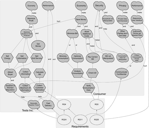
The goal graphs serve two purposes. First, to refine the top-level goals to the leaves. For example, refine “Privacy” to “Private Data not Disclosed” to “Authorized Parties get Needed Data.” For the further procedure the leaves (goals without sub-goals) are of specific interest. For Tesla Inc. these are “Establish & Maintain Reputation,” “Collect Maximum of Information,” “Collect Customer Information,” “Reasonable Reaction Times,” and “Fast Delivery.” “Household not Manipulated,” “Responsive User Interface,” “Authorized Parties get Needed Data,” “Bill not Manipulated,” “Consumption Data not Manipulated,” “Analyze Consumption,” “Communicate Confidential,” and “Verify Consumption Data” are the leaves for the consumer. The leaves will serve as criteria for the valuation.
The second purpose is the use of the graphs for the optimization. The graphs already contain alternatives for fulfilling the goals. Every or contribution like “Minimize Consumption” and “Optimize Consumption” for the soft goal “Minimize Bill” is an option for optimization. Additionally, whenever a goal cannot be fulfilled, all of its sub-goals do not have to be fulfilled. Hence, all requirements related to these sub-goals can be ignored. As result, the goal graphs serve for constraining the optimization and adding alternatives.
4.3.2 Understanding the problem
The phase Understanding the Problem aims at understanding the system-to-be and the problem it shall solve, and therefore understanding the environment it should influence according to the requirements. In the first step Problem Context Elicitation, we obtain a problem description by eliciting all domains related to the problem to be solved, their relations to each other, and the software to be constructed. The step Functional Requirements Elicitation is concerned with decomposing the overall problem into sub-problems that describe a certain functionality, as expressed by a set of related requirements. The functionality of the software is the core, and all quality requirements are related in some way to this core. Eliciting quality requirements and relating them to the system-to-be is achieved in the step Quality Requirements Elicitation. Once eliciting the functional and quality requirements is accomplished, one has to ensure that the system-to-be complies to regulations such as laws. To this end, we derive requirements from laws, standards, and policies in the step Compliance Requirements Elicitation.
To elicit the problem context, we set up a context diagram consisting of the machine Gateway, the domains LMN, HAN, WAN, MeterData, AuthorizedExternalEntities, Consumer, etc. and interfaces between these domains. To provide billing information to external parties and also to the consumer, the gateway receives the meter data from the meter(s) (RQ1), processes it (RQ2), and stores it (RQ3). The gateway submits the stored data to external parties (RQ4). The stored data can also be provided to the consumer to allow the consumer to verify an invoice (RQ5). We set up problem diagrams to model the functional requirements RQ1-RQ5. Figure 4.3 shows the problem diagram for the functional requirement RQ4. Besides the functionalities that the gateway has to provide, it is also responsible for the protection of authenticity, integrity, and confidentiality of data temporarily or persistently stored in the gateway, transferred locally within the LAN and transferred in the WAN (between gateway and authorized external entities). In addition, as stated by the protection profile (Kreutzmann et al., 2011), the privacy of the consumer shall be protected. Furthermore, it is demanded that functional requirements shall be achieved within a certain response time.
Hence, we annotate all problem diagrams with quality requirements as proposed in earlier work of ours (Alebrahim et al., 2011a). For example, we annotate the problem diagram for submitting meter readings (Figure 4.3) with security requirements RQ10 (integrity), RQ11 (confidentiality), RQ12 (authenticity), which complement the functional requirement RQ4. The privacy requirement RQ17 and the performance requirement RQ24 also complement the functional requirement RQ4.
4.4 Method for Detecting Candidates for Requirements Interactions
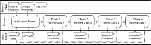
The first step for reconciliation is to discover interactions between requirements. Interactions can be positive or negative. In this section, we deal with negative interactions involving quality requirements, leading to undesirable effects among requirements. In the following, we propose a method to detect candidates for negative interactions based on pairwise comparisons between quality requirements. Figure 4.6 illustrates the phases of our method, input, and output of each phase.
To restrict the number of comparisons, we perform a preparation phase, in which we investigate which two types of quality requirements may be in conflict in general. In doing so, we consider different types of quality requirements. The preparation phase results in a table containing all types of quality requirements to be considered. We compare each two types of quality requirements regarding potential conflicts. If conflicts are possible, we enter a cross in the cell, where the two quality requirements cross, otherwise a minus. For example, no interactions between a confidentiality requirement and a privacy requirement are expected. Therefore, the cell crossing these two requirement types in the table contains a minus. In contrast, a confidentiality requirement might be in conflict with a performance requirement. Hence, the corresponding cell contains a cross. Table 4.2 shows possible interactions among security (confidentiality, integrity, authenticity), performance, and privacy requirements in general.
Table 4.2
Possible Interactions among Types of Quality Requirements in General
| Confidentiality | Integrity | Authenticity | Performance | Privacy | |
| Confidentiality | – | – | x | x | – |
| Integrity | – | – | – | x | – |
| Authenticity | x | – | – | x | – |
| Performance | x | x | x | x | x |
| Privacy | – | – | – | x | – |
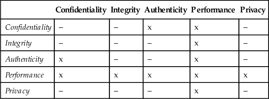
Interactions among quality requirements of different types can occur either between quality requirements related to the same functional requirement or among those related to different functional requirements. We classify quality requirements and their relations to the functional requirements into four cases (see Table 4.3). Case one arises when we consider two quality requirements of the same type related to the same functional requirement. The second case is concerned with considering two quality requirements of different types that are related to the same functional requirement. Case three occurs when two quality requirements of the same type but related to different functional requirements must be achieved in parallel. In the fourth case, two quality requirements of different types and related to different functional requirements must be achieved in parallel. We treat each case in a separate phase in our method. The result of this classification is represented in Table 4.3. The abbreviations FRQ and QRQ stand for “Functional Requirement” and “Quality Requirement,” respectively.
Table 4.3
Classification Table
| Case | FRQ, Type of QRQ | Condition | Row in QRQ Table | Method’s Phase |
| Case 1 | Same FRQ, same type of QRQ | – | Rows related to same FRQ in same QRQ table | Phase 1 |
| Case 2 | Same FRQ, different types of QRQ | – | Rows related to same FRQ in different QRQ tables | Phase 2 |
| Case 3 | Different FRQ, same type of QRQ | In parallel | Rows related to different FRQ in same QRQ table | Phase 3 |
| Case 4 | Different FRQ, different types of QRQ | In parallel | Rows related to different FRQ in different QRQ tables | Phase 4 |

The general principle of our method for detecting interactions among requirements is using the structure of problem diagrams to identify the domains where quality requirements might interact. Such domains are trade-off points. When the state of a domain can be changed by one or more sub-machines at the same time, their related quality requirements might be in conflict. We express this situation in the problem diagrams by dependencies that constrain such domains. Therefore, to detect interactions we set up tables where the columns contain information about quality-relevant domains (possible trade-off points) from the problem diagrams, and the rows contain information about quality requirements under consideration. We enter crosses in the cells whenever the state of a domain can be changed for the achievement of the corresponding quality requirement. In the following, we describe the method and its application to the smart grid example in more detail.
4.4.1 Initialization phase: Initial setup
In this phase, we make use of the structure of the problem diagrams and contained information regarding quality requirements (domain knowledge, see input in Figure 4.6) to set up the initial QRQ tables. These tables are used for the identification of interactions among quality requirements in later phases. Furthermore, we set up life cycle expressions that represent the order in which the requirements must be achieved.
4.4.1.1 Set up initial tables
For each type of quality requirement, we identify which domains are constrained by it. This results in initial QRQ tables, where the columns contain information about quality-relevant domains from the problem diagrams, and the rows contain information about quality requirements under consideration. We enter a cross in each cell, when a domain—given by the column—is relevant for the quality requirement under consideration—given by the row. For each type of quality requirement, we set up such a table. The second column in each table names the functional requirement related to the quality requirement given in the first column.
When we deal with performance, we need domain knowledge that is necessary to achieve performance requirements. As mentioned in Section 4.2.2, we apply the MARTE profile to annotate performance requirements accordingly.
Performance is concerned with the workload of the system and the available resources to process the workload (Klein, 2000). The workload is described by triggers of the system, representing requests from outside or inside the system. Workload exhibits the characteristics of the system use. It includes the number of requests (e.g., number of concurrent users) and their arrival pattern (how they arrive at the system). The arrival pattern can be periodic (e.g., every 10 ms), stochastic (according to a probabilistic distribution), or sporadic (not to capture by periodic or stochastic characterization) (Bass et al., 2003). To model workload, we make use of the stereotype ![]() GaWorkloadEvent
GaWorkloadEvent ![]() , which may be generated by an ArrivalPattern such as the ClosedPattern that allows us to model a number of concurrent users and a think time (the time a user waits between two requests) by instantiating the attributes population and extDelay.
, which may be generated by an ArrivalPattern such as the ClosedPattern that allows us to model a number of concurrent users and a think time (the time a user waits between two requests) by instantiating the attributes population and extDelay.
Processing the requests requires resources. Each resource is modeled by its type, such as CPU, memory, I/O device, network, utilization, and capacity (e.g., the transmission speed for a network). In order to elicit relevant resources required for performance analysis as domain knowledge, we have to check whether each domain represents or contains any hardware device that the system is executed on or any resource that can be consumed to achieve the corresponding performance requirement. If the domain is a performance-relevant resource, it has to be annotated as such a resource. To this end, we make use of stereotypes provided by MARTE. For example, for a hardware memory, MARTE provides the stereotype ![]() HwMemory
HwMemory ![]() . Other possible stereotypes from MARTE are
. Other possible stereotypes from MARTE are ![]() DeviceResource
DeviceResource ![]() ,
, ![]() HwProcessor
HwProcessor ![]() , and
, and ![]() HwMedia
HwMedia ![]() . In our example, the domains LMN, HAN, and LAN represent communication resources. Hence, we annotate them with the stereotype
. In our example, the domains LMN, HAN, and LAN represent communication resources. Hence, we annotate them with the stereotype ![]() HwMedia
HwMedia ![]() . The domain smartMeter represents a device resource and is annotated with the stereotype
. The domain smartMeter represents a device resource and is annotated with the stereotype ![]() DeviceResource
DeviceResource ![]() .
.
In some cases, it is possible that the domain itself represents no resource, but it contains a hidden resource with performance-relevant characteristics that has to be modeled explicitly. For example, it may contain a CPU, which is relevant when talking about performance issues. In this case, the hidden resource has to be modeled explicitly as a causal domain. It additionally has to be annotated with a stereotype from the MARTE profile representing the kind of resource it provides. In the smart grid example, Gateway is the machine (software we intend to build) that contains the resource CPU. Hence, all sub-machines from problem diagrams contain the resource CPU, which we model explicitly as a causal domain with the stereotype ![]() HwProcessor
HwProcessor ![]() .
.
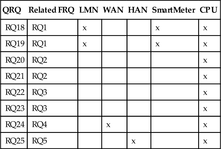
So far, we have elicited and modeled the domain knowledge that we need to set up the initial performance table. In this table, similarly to other initial QRQ tables, columns contain information about quality-relevant domains from problem diagrams (resources in case of performance requirements) and rows contain information about quality requirements under consideration. Table 4.4 presents the initial performance table.
Table 4.4
Initial Performance Table
| QRQ | Related FRQ | LMN | WAN | HAN | SmartMeter | CPU |
| RQ18 | RQ1 | x | x | x | ||
| RQ19 | RQ1 | x | x | x | ||
| RQ20 | RQ2 | x | ||||
| RQ21 | RQ2 | x | ||||
| RQ22 | RQ3 | x | ||||
| RQ23 | RQ3 | x | ||||
| RQ24 | RQ4 | x | x | |||
| RQ25 | RQ5 | x | x |
Initial tables for integrity, authenticity, and confidentiality for our example are given in Tables 4.5 and 4.6. Note that we have to consider CPU as a domain whenever we want to detect interactions among performance and security requirements. The reason is that CPU time is consumed for the achievement of security requirements.


4.4.1.2 Set up life cycle
In this step, we use lightweight life cycle expressions to describe the relations between the functional requirements of the corresponding sub-problems to be achieved to solve the overall problem. The life cycle contains information about the order in which the requirements must be achieved. The following expression represents the life cycle for our example: LC = (RQ1; RQ2; RQ3)* || RQ4* || RQ5*.
The expression RQ1; RQ2 indicates that RQ1 has to be achieved before RQ2 is achieved. The expression RQ4 || RQ5 describes that RQ4 and RQ5 have to be achieved concurrently. RQ4* indicates that RQ4 has to be achieved for 0 or more times. The complete life cycle LC stipulates that RQ1, RQ2, and RQ3 must be achieved sequentially for 0 or more times, while RQ4 and RQ5 must be achieved in parallel to each other and to the sequence of RQ1; RQ2; RQ3 for 0 or more times. This means, the meter readings have to be received first (RQ1). Then they have to be processed (RQ2) before storing them (RQ3). This can be achieved for 0 or more times. In parallel, the meter readings can be sent to external entities (RQ4) and consumers (RQ5) for 0 or more times.
4.4.2 Phase 1: Treating case 1
In this phase, we compare the rows in each table to identify potential conflicts among quality requirements concerning the first case of Table 4.3. The aim is to detect conflicts among the same type of quality requirements that are related to the same functional requirement. To deal with this case of requirements conflicts, we consider each table separately.
Step 1.1:Eliminating irrelevant tables. To eliminate irrelevant tables, we make use of the initial interaction table (Table 4.2) we set up before. According to this table, interactions among quality requirements of the same type can only happen when considering two performance requirements. Therefore, we mark Tables 4.5 (left), 5 (right), and 6 as irrelevant for requirements interactions and continue only with Table 4.4 for the treatment of first case.
Step 1.2: Eliminating irrelevant rows. In each table under consideration, we perform a pairwise comparison between quality requirements related to the same functional requirement. We check, if such quality requirements constrain the same domains (contain crosses in the same columns). We consider the rows related to such quality requirements as relevant and remove the irrelevant rows from Table 4.4. Doing so, we obtain Table 4.7. We also removed the columns WAN and HAN, because they did not contain any entry after removing irrelevant rows.
Table 4.7
Phase 1, Step 1.2: New Performance Table
| QRQ | Related FRQ | LMN | SmartMeter | CPU |
| RQ18 | RQ1 | x | x | x |
| RQ19 | RQ1 | x | x | x |
| RQ20 | RQ2 | x | ||
| RQ21 | RQ2 | x | ||
| RQ22 | RQ3 | x | ||
| RQ23 | RQ3 | x |

Step 1.3: Detecting interaction candidates. Considering the new performance table from the previous step, we look at each two rows sharing the same functional requirement. We determine that the requirements RQ18 and RQ19 share the same domains LMN, SmartMeter, and CPU. Further, the requirements RQ20 and RQ21 share the same domain CPU. The same is the case for the requirements RQ22 and RQ23. We identify these requirements as candidates for requirement interactions. Table 4.8 summarizes all detected interaction candidates.
Table 4.8
Candidates of Requirements Interactions
| Method’s Phase | Comparison Between Tables | Interaction Candidates |
| Phase 1 | Table 4.4 with itself | RQ18 and RQ19, RQ20 and RQ21, RQ22 and RQ23 |
| Phase 2 | Table 4.4 with Table 4.5 (left) | RQ6 and RQ18, RQ6 and RQ19, RQ10 and RQ24, RQ13 and RQ25 |
| Table 4.5 (right) with Table 4.6 | RQ7 and RQ8, RQ11 and RQ12, RQ14 and RQ15, RQ16 and RQ8 | |
| Table 4.4 with Table 4.5 (right) | RQ8 and RQ18, RQ8 and RQ19, RQ12 and RQ24, RQ15 and RQ25 | |
| Table 4.6 with Table 4.4 | RQ7 and RQ18, RQ7 and RQ19, RQ11 and RQ24, RQ14 and RQ25, RQ16 and RQ18, RQ16 and RQ19, RQ9 and RQ22, RQ9 and RQ23 | |
| Phase 3 | Table 4.4 with itself | RQ18 and RQ24, RQ18 and RQ25, RQ19 and RQ24, RQ19 and RQ25, RQ20 and RQ24, RQ20 and RQ25, RQ21 and RQ24, RQ21 and RQ25, RQ22 and RQ24, RQ22 and RQ25, RQ23 and RQ24, RQ23 and RQ25, RQ24 and RQ25, RQ18 and RQ20, RQ19 and RQ20, RQ18 and RQ21, RQ19 and RQ21, RQ18 and RQ22, RQ19 and RQ22, RQ18 and RQ23, RQ19 and RQ23, RQ20 and RQ22, RQ21 and RQ22, RQ20 and RQ23, RQ21 and RQ23 |
| Phase 4 | Table 4.5 (left) with Table 4.4 | RQ6 and RQ20, RQ6 and RQ21, RQ6 and RQ22, RQ6 and RQ23, RQ6 and RQ24, RQ6 and RQ25, RQ10 and RQ18, RQ10 and RQ19, RQ10 and RQ20, RQ10 and RQ21, RQ10 and RQ22, RQ10 and RQ23, RQ10 and RQ25, RQ13 and RQ18, RQ13 and RQ19, RQ13 and RQ20, RQ13 and RQ21, RQ13 and RQ22, RQ13 and RQ23, RQ13 and RQ24 |
| Table 4.6 with Table 4.4 | RQ7 and RQ24, RQ7 and RQ25, RQ16 and RQ24, RQ16 and RQ25, RQ9 and RQ24, RQ9 and RQ25, RQ11 and RQ18, RQ11 and RQ19, RQ11 and RQ20, RQ11 and RQ21, RQ11 and RQ22, RQ11 and RQ23, RQ11 and RQ25, RQ14 and RQ18, RQ14 and RQ19, RQ14 and RQ20, RQ14 and RQ21, RQ14 and RQ22, RQ14 and RQ23, RQ14 and RQ24, RQ9 and RQ18, RQ9 and RQ19, RQ9 and RQ20, RQ9 and RQ21, RQ7 and RQ20, RQ7 and RQ21, RQ7 and RQ22, RQ7 and RQ23, RQ16 and RQ20, RQ16 and RQ21, RQ16 and RQ22, RQ16 and RQ23 | |
| Table 4.5 (right) with Table 4.4 | RQ8 and RQ20, RQ8 and RQ21, RQ8 and RQ22, RQ8 and RQ23, RQ8, and RQ24, RQ8 and RQ25, RQ12 and RQ18, RQ12 and RQ19, RQ12 and RQ20, RQ12 and RQ21, RQ12 and RQ22, RQ12 and RQ23, RQ12 and RQ25, RQ15 and RQ18, RQ15 and RQ19, RQ15 and RQ20, RQ15 and RQ21, RQ15 and RQ22, RQ15 and RQ23, RQ15 and RQ24 |

4.4.3 Phase 2: Treating case 2
This phase is concerned with the second case of Table 4.3, dealing with possible conflicts among different types of quality requirements related to the same functional requirement. Hence, we compare quality requirements related to the same functional requirement in each two tables to identify potential conflicts.
Step 2.1: Eliminating irrelevant tables. To eliminate irrelevant tables, we make use of the initial interaction table (Table 4.2) to determine which two tables should be compared with each other. For our example, we can reduce the number of table comparisons to four: 4.5 (left) and 4.4, 4.6 and 4.5 (right), 4.6 and 4.4, 4.5 (right) and 4.4.
Note that in each phase, we have to consider the initial QRQ tables such as Table 4.4 and not the new reduced tables such as 4.7. The reason is that in each phase, we eliminate different rows from the initial QRQ tables according to Table 4.3.
Step 2.2: Detecting interaction candidates. To identify interactions among quality requirements related to the same functional requirement, we have to look in different tables at the rows with the same related functional requirement and check, if same the domains (columns) contain crosses. Such requirements are candidates for interactions.
This is mostly the case for performance and security requirements. The reason is that solutions for achieving security requirements are time-consuming and this is at the expense of performance. As an example, we describe how we compare the Tables 4.5 (left) and 4.4. We consider the rows related to the same functional requirement. The rows related to the functional requirement RQ1 contain entries in the columns LMN and CPU. This implies that we might have a conflict between the integrity requirement RQ6 and the performance requirements RQ18 and RQ19. Comparing each further two rows results in the following potential conflicts: RQ10 with RQ24, and RQ13 with RQ25. Table 4.8 summarizes all detected interaction candidates.
4.4.4 Phase 3: Treating case 3
In this phase, we deal with case three of Table 4.3. In other words, we consider different functional requirements complemented with the same type of quality requirement. Table 4.2 enables us to eliminate irrelevant tables. Additionally, we make use of the information contained in the life cycle expression regarding the concurrent achievement of requirements.
Step 3.1: Eliminating irrelevant tables. According to Table 4.3, we have to consider each table separately. According to Table 4.2, no interactions will occur among different integrity, confidentiality, and authenticity requirements. Hence, we mark Tables 4.5 (left), 4.5 (right), and 4.6 as irrelevant. The only type of quality requirements to be considered are performance requirements as given in Table 4.4.
Step 3.2: Eliminating irrelevant rows. In each table under consideration, we perform a pairwise comparison between the rows. According to Table 4.3, interactions can only arise when quality requirements must be satisfied in parallel. We make use of the life cycle expression to identify requirements that must be achieved in parallel. According to the life cycle, we cannot eliminate any row in Table 4.4, because although the requirements RQ1, RQ2, and RQ3 can be satisfied sequentially, they must be achieved in parallel with the requirements RQ4 and RQ5.
Step 3.3: Detecting interaction candidates. In this step, we check if the requirements with parallel satisfaction contain entries in the same column. We see in Table 4.4 that all requirements concern the same domain CPU. Therefore, we identify a number of interaction candidates as given in Table 4.8.
4.4.5 Phase 4: Treating case 4
This phase is concerned with case four of Table 4.3, which deals with different functional requirements complemented with different types of quality requirements. Table 4.2 enables us to eliminate irrelevant tables. Additionally, we take the life cycle expression into account to reduce the number of comparisons within each table.
Step 4.1:Eliminating irrelevant tables. According to Table 4.2, we can reduce the number of table comparisons to three: 4.5 (left) and 4.4, 4.6 and 4.4, 4.5 (right) and 4.4.
Step 4.2: Eliminating irrelevant rows. According to the life cycle, although the requirements RQ1, RQ2, and RQ3 must be achieved sequentially, they must be achieved in parallel to requirements RQ4 and RQ5. Therefore, we cannot remove any row from the tables under consideration.
Step 4.3: Detecting interaction candidates. According to Table 4.2 and the results obtained from the previous steps, we only have to compare the rows in the following three tables: 4.5 (left) and 4.4, 4.6 and 4.4, 4.5 (right) and 4.4. We get a large number of interaction candidates between the integrity and performance requirements, confidentiality and performance requirements, as well as authenticity and performance requirements. Table 4.8 presents the overall result of applying the method.
Discussion of the results. At this point, we have to check if we can reduce the number of interaction candidates. Looking at the result, we see that most interactions might be among performance and security requirements and among different performance requirements. Additionally, we identified three pairs of interaction candidates among authenticity and confidentiality requirements (Table 4.8, phase 2). We figure out that the interaction depends on the order of applying confidentiality and authenticity solution mechanisms. If we sign the data first and then encrypt it, we can achieve both confidentiality and authenticity. The other way around, if we encrypted the data first and then signed it, the confidentiality and authenticity requirements would interact with each other. Under this condition, we can exclude interactions among requirement pairs RQ7 and RQ8, RQ11 and RQ12, RQ14 and RQ15 (crossed out in Table 4.8). Of course, we have to document this condition for the design and implementation phases. All other candidates have to be taken into account in the subsequent phases of the QuaRO method.
4.5 Method for Generation of Alternatives
To enable the optimization for obtaining a final set of requirements that is as near to the optimal solution for every stakeholder as possible, we need to generate alternatives for the problematic requirements. Hence, an original requirement might be excluded from the final set, but a weaker variant of this requirement might be included in the optimal set of requirements. For example, for security requirements there can be certain kinds of attackers we want to be secured against. However, we maybe cannot address a strong attacker with certain properties such as the given time and resource limits. Hence, we propose a method for relaxing such properties in order to generate alternatives for problematic requirements. Generated alternatives are used as recommendations for stakeholders. Those alternatives that are not acceptable for stakeholders are excluded before they are used as input for the next step of the method. Figure 4.7 illustrates the steps of our method, input, and output of each step.

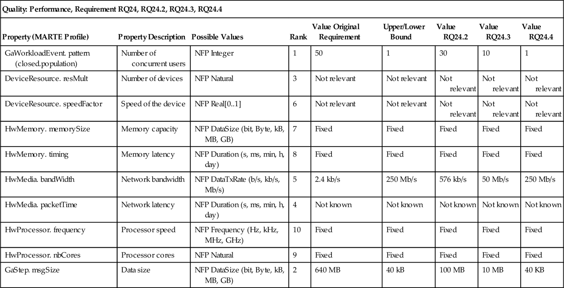
Based on the type of requirement we want to generate alternatives for, there are different properties, which are candidates to be relaxed. The qualities addressed by different requirements are very different, and as a result, so are the properties, which can be used to relax a requirement. But for particular kinds of qualities those properties are the same. Hence, it is possible to define a property template for a quality, which can be instantiated for a requirement belonging to this quality. For each quality, we capture the following information in the template (see Tables 4.9 and 4.10): Property describing the quality-relevant properties, Possible Values describing the range of values the property can take, Rank representing the property that can be most likely relaxed according to stakeholder preferences, Value Original Requirement representing the value of property for the original requirement before relaxing, Upper/Lower Bound describing the lower or upper bound (depending to the property) each property can take when relaxing, and Value RQ representing the values of the relaxed properties for requirements alternatives. In the following, we present the templates for the qualities security and performance before we introduce our method for generating alternatives.
Table 4.9
Security Relaxation Template and Its Instantiation for RQ11
| Quality: Security, Requirement RQ11, Alternatives RQ11.2, RQ11.3, RQ11.4 | |||||||
| Property (CEM) | Possible Values | Rank | Value Original Requirement | Upper/Lower Bound | Value RQ11.2 | Value RQ11.3 | Value RQ11.4 |
| Preparation time | 1 day, 1 week, 2 weeks, 1 month, 2 months, 3 months, 4 months, 5 months, 6 months, more than 6 months | 3 | More than 6 months | 1 month | 4 months | 2 months | 1 month |
| Attack time | 1 day, 1 week, 2 weeks, 1 month, 2 months, 3 months, 4 months, 5 months, 6 months, more than 6 months | 5 | More than 6 months | 1 month | More than 6 months | 3 months | 1 month |
| Specialist expertise | Laymen, proficient, expert, multiple experts | 6 | Multiple experts | Proficient | Multiple experts | Expert | Proficient |
| Knowledge of the TOE | Public, restricted, sensitive, critical | 1 | Public | Public | Public | Public | Public |
| Window of opportunity | Unnecessary/unlimited, easy, moderate, difficult | 2 | Difficult | Difficult | Difficult | Difficult | Difficult |
| IT hardware/software or other equipment | Standard, specialized, bespoke, multiple bespoke | 4 | Multiple bespoke | Bespoke | Multiple bespoke | Multiple bespoke | Bespoke |

Table 4.10
Performance Relaxation Template and Its Instantiation for RQ24
| Quality: Performance, Requirement RQ24, RQ24.2, RQ24.3, RQ24.4 | ||||||||
| Property (MARTE Profile) | Property Description | Possible Values | Rank | Value Original Requirement | Upper/Lower Bound | Value RQ24.2 | Value RQ24.3 | Value RQ24.4 |
| GaWorkloadEvent. pattern (closed.population) | Number of concurrent users | NFP Integer | 1 | 50 | 1 | 30 | 10 | 1 |
| DeviceResource. resMult | Number of devices | NFP Natural | 3 | Not relevant | Not relevant | Not relevant | Not relevant | Not relevant |
| DeviceResource. speedFactor | Speed of the device | NFP Real[0..1] | 6 | Not relevant | Not relevant | Not relevant | Not relevant | Not relevant |
| HwMemory. memorySize | Memory capacity | NFP DataSize (bit, Byte, kB, MB, GB) | 7 | Fixed | Fixed | Fixed | Fixed | Fixed |
| HwMemory. timing | Memory latency | NFP Duration (s, ms, min, h, day) | 8 | Fixed | Fixed | Fixed | Fixed | Fixed |
| HwMedia. bandWidth | Network bandwidth | NFP DataTxRate (b/s, kb/s, Mb/s) | 5 | 2.4 kb/s | 250 Mb/s | 576 kb/s | 50 Mb/s | 250 Mb/s |
| HwMedia. packetTime | Network latency | NFP Duration (s, ms, min, h, day) | 4 | Not known | Not known | Not known | Not known | Not known |
| HwProcessor. frequency | Processor speed | NFP Frequency (Hz, kHz, MHz, GHz) | 10 | Fixed | Fixed | Fixed | Fixed | Fixed |
| HwProcessor. nbCores | Processor cores | NFP Natural | 9 | Fixed | Fixed | Fixed | Fixed | Fixed |
| GaStep. msgSize | Data size | NFP DataSize (bit, Byte, kB, MB, GB) | 2 | 640 MB | 40 kB | 100 MB | 10 MB | 40 KB |
4.5.1 Relaxation template for security
For security it is the type of attacker that influences the restrictiveness of a security requirement. How much resources and effort to spend on a requirement, how much influence security has on the behavior of the overall system-to-be, and which solution has to be chosen to fulfill the requirement later on all depend on the abilities of the attacker. While it is almost impossible to secure a system against an almighty attacker, defending against a layman (see International Organization for Standardization (ISO) and International Electrotechnical Commission (IEC), 2009) can be easily achieved without big impact on the rest of the system.
To describe the attacker, we use the properties as described by the Common Methodology for Information Technology Security Evaluation (CEM) (International Organization for Standardization (ISO) and International Electrotechnical Commission (IEC), 2009) for vulnerability assessment of the TOE (target of evaluation i.e., system-to-be). How to integrate this attacker description into problem frames is described in earlier work of ours (Hatebur and Heisel, 2009b, 2010a). The properties to be considered (according to CEM) are (International Organization for Standardization (ISO) and International Electrotechnical Commission (IEC), 2009):
Elapsed time “Elapsed time is the total amount of time taken by an attacker to identify a particular potential vulnerability …, to develop an attack method and … to mount the attack …” We distinguish between the preparation time and the attack time.
Specialist expertise “Specialist expertise refers to the level of generic knowledge of the underlying principles, product type or attack methods ….”
Knowledge of the TOE “Knowledge of the TOE refers to specific expertise in relation to the TOE.”
Window of opportunity “Identification or exploitation of a vulnerability may require considerable amounts of access to a TOE that may increase the likelihood of detection. … Access may also need to be continuous, or over a number of sessions.”
IT hardware/software or other equipment “… the equipment required to identify or exploit a vulnerability.”
The resulting relaxation template is shown in Table 4.9.
4.5.2 Relaxation template for performance
As described in Section 4.4.1, in the initialization phase, analyzing the context of performance requires a focus on two issues, namely the workload behavior, described by an arrival pattern, and the number of requests and the resources, described by utilization and capacity. For modeling this information we use the MARTE profile (UML Revision Task Force, 2011), which is integrated into UML4PF in our previous work (Alebrahim et al., 2011b).
GaWorkloadEvent represents the kind of arrival pattern. A ClosedPattern is one kind of arrival pattern. It contains the attribute population that represents a fixed number of active users (UML Revision Task Force, 2011, pp. 308, 503).
DeviceResource represents an external device. It contains the attribute resMult that represents the maximum number of available instances of a particular resource (UML Revision Task Force, 2011, p. 613). The attribute speedFactor gives the relative speed of the unit as compared to the reference one (UML Revision Task Force, 2011, p. 506).
HwMemory contains the attributes memorySize that specifies the storage capacity and timing that specifies timings of the HwMemory (UML Revision Task Force, 2011, p. 597).
HwMedia is a communication resource that represents a means to transport information from one location to another. It contains the attributes bandWidth specifying the transfer bandwidth and packetTime specifying the time to transmit an element (UML Revision Task Force, 2011, p. 598).
HwProcessor is a generic computing resource symbolizing a processor. It contains the attributes nbCores, which specifies the number of cores within the HwProcessor and frequency (not contained in the specification, but in the implementation) (UML Revision Task Force, 2011, p. 670).
GaStep is part of a scenario and contains the attribute msgSize, which specifies the size of a message to be transmitted by the Step (UML Revision Task Force, 2011, p. 306).
The used types NFP _ … are complex data types defined in the MARTE profile (UML Revision Task Force, 2011). The resulting relaxation template for performance is shown in Table 4.10.
In the following, we describe our method to generate alternatives for interacting requirements to be used in further steps of QuaRO method (see Figure 4.7).
1. Select pair of interacting requirements. Table 4.8 is the input for the generation of alternatives. We have to analyze each pair for possible alternative requirements, which resolve or relax the interaction.
For our example, we select the requirements pair RQ11 and RQ24.
2. Select first/second requirement. For the selected pair, we have to check each of the two requirements for possibilities to resolve the interaction. Hence, we have to execute the next steps for both requirements.
Both requirements provide the possibility to be relaxed in order to resolve the interaction. Hence, we perform the next steps for both requirements RQ11 and RQ24. In Tables 4.9 and 4.10, we fill the column “value original requirement” for these two requirements. Because there is no information in the Protection Profile about the attacker that the system must be protected against, we assume that the system must be protected against the strongest attacker. Hence, we select for each property the strongest one to obtain values for original requirement RQ11. To fill the properties for the column “value original requirement” for the performance requirement RQ24, we need additional information that is missing in the Protection Profilep Kreutzmann et al., 2011) and Open Meter (Remero et al., 2009a) documents. Hence, we looked for the necessary domain knowledge in the existing literature (Deconinck, 2008; Stromanbieter Deutschland, 2013). Based on this search, we assume the values given in column “value original requirement” in Table 4.10. The rest of properties is fixed (cannot be relaxed), unknown or irrelevant for the requirement RQ24.
3. Check decomposition potential of requirements. In the case of a complex requirement, it might help to separate the source of interaction from the rest of the requirement. The separated requirements can be treated differently. It might happen that an interaction would lead to a rejection of the whole complex requirement. In contrast, for the decomposed set of requirements, some parts of the original requirement might remain in the solution.
The quality requirements R11 and R24 complement the functional requirement R4, which is concerned with submitting meter data to external entities. This is not a complex problem and cannot be decomposed further. Hence, the related quality requirements cannot be decomposed further.
4. Execute and model decomposition. If a decomposition is possible, it has to be executed, and the result has to be modeled.
The selected requirements R11 and R24 cannot be decomposed.
5. Select remaining interacting sub-requirements. In case of a decomposition, only the sub-requirement, which is the source of the interaction, has to be analyzed further.
We did not decompose the requirements R11 and R24. Hence, they have to be considered in next steps.
6. Identify relaxation property candidates. Based on the type of requirement, there are different properties, which are candidates to be relaxed. These candidates are fixed for each kind of requirement. Hence, we can use predefined templates to identify these properties. For each property the actual value regarding the interacting requirement has to be stated. Next, it has to be decided if this value for the property is a hard constraint, which cannot be changed, or a soft constraint, which might be relaxed. In the second case, we identified a relaxation candidate.
For the security requirement RQ11 (Table 4.9), we figure out that the properties “knowledge of the TOE” and “window of opportunity” are fixed and cannot be relaxed. The rest of properties can be relaxed to generate alternatives for the original requirement RQ11. For the performance requirement RQ24 (Table 4.10) the characteristics of memory, namely “HwMemory.memorySize” and “HwMemory.timing” and the characteristics of processor, namely “HwProcessor.frequency” and “HwProcessor.nbCores” for the gateway are fixed. The rest of the properties can be used for relaxation, if they are known and relevant.
7. Rank relaxation property candidates. When talking about reasonable relaxations, it is also important to know which properties are more important to the overall requirement than others.
The ranks to the requirements RQ11 and RQ24 can be found in Tables 4.9 and 4.10.
8. Identify upper/lower relaxation bounds. For each property, the upper/lower bound, which is still acceptable, has to be identified. The upper/lower bounds of all properties form the worst-case scenario, which is still acceptable for a requirement.
To identify “upper/lower bounds” for the requirement RQ11, we have to assume values from the possible values, because we have no information about the strength of the attacker. Hence, we assume that the system has to be protected at least against an attacker who is a “proficient,” has “1 month” for preparing the attack, has “1 month” for the attack itself, and has a “bespoke” equipment for performing the attack. To identify “upper/lower bounds” for the requirement RQ24, we begin with the property “GaWorkloadEvent.pattern(closed.population),” which represents the number of concurrent users. For the case that the gateway sends meter readings to the external entities via a concentrator, there is only one user. Hence, we take 1 for the column “upper/lower bound.” As “upper/lower bound” for the property “HwMedia.bandWidth,” we take the bandwidth of Power Line Communication (PLC) that can be up to 250 Mb/s. The “upper/lower bound” for the property “GaStep.msgSize” is assumed to be 40 kB (Deconinck, 2008).
9. Generate and model alternatives. The first alternative is the requirement realizing the worst-case scenario. Between the original requirement and this lower bound requirement, several other requirements can be generated by varying the relaxation candidates. For each generated requirement, it has to be checked, regardless of whether it eliminates the interaction. If it does not, further relaxation is needed. The generated alternatives have to be modeled.
To relax the properties and thus generate alternatives for the requirements RQ11 and RQ24, we choose values between the “value original requirement” and “upper/lower bound” for properties that can be relaxed. For example, for the requirement RQ24 the properties “GaWorkloadEvent.pattern (closed.population),” “HwMedia.bandWidth,” and “GaStep.msgSize” can be relaxed. The rest of the properties are either fixed or irrelevant for the corresponding requirement or unknown and thus cannot be considered for the relaxation process. Relaxing possible properties results in requirements alternatives RQ11.2, RQ11.3, and RQ11.4 for the original requirement RQ11 and in requirements alternatives RQ24.2, RQ24.3, and RQ24.4 for the original requirement RQ24. In this way, we cannot say that we assuredly resolve interactions between quality requirements, but we can weaken them for sure or even resolve them ideally.
4.6 Valuation of Requirements
For optimization, the requirements need a value to which the optimization can refer. The relations between requirements also need to be valuated. This can be achieved by prioritization in the form of cost estimations or statistical metrics. The valuating measure or method has to be selected in this step, and the values for the requirements have to be elicited. Furthermore, the valuation has to be documented for later use. The valuation of a requirement can differ from stakeholder to stakeholder.
For the QuaRO we decided to use ANP for valuation of requirements. There are several reasons for this decision:
Capture complexity of the decision problem. As we see from the goal model and the relations between goals, requirements, and requirement alternatives, we have a very complex decision problem. Even the decision about the value or rank of a requirement is not straightforward. ANP allows one to model the decision problem coherently to the real problem as described and modeled by the preliminary steps. For AHP, Even Swaps, or simple ranking, simplifications would be needed, making the outcome unreliable (Saaty, 2008b).
Reduce complexity of decisions. In ANP decisions are reduced to pairwise comparison. This has been proven to be the most natural decision a person can make (Saaty, 2005).
Coping with fuzzy values. ANP does not require giving concrete numbers for a value of a requirement or goal but relies on relative comparisons (Saaty, 2005). This is an important property because giving fixed numbers can hardly be achieved in the early phases of software engineering. Furthermore, ANP has proven to be one of the most reliable decision techniques for fuzzy environments (Saaty, 2008b).
Detecting and handling inconsistencies. ANP allows one to compute and check the consistency of the different comparisons. Thus, inconsistencies can be avoided. However, ANP even works for comparisons with small-scale inconsistencies (Saaty, 2005).
Merging of different views and dimensions for a decision. ANP allows one to merge results for different dimensions, like benefits and costs, of a decision. Furthermore, it is easy to integrate different views of different stakeholders (Saaty, 2005; Saaty and Ozdemir, 2003).
Tool support. For ANP, there are different support tools.6
Up to this point, we covered only step 1 of ANP as described by Saaty (2008b) (Section 4.2.3). The steps for setting up the QuaRO-ANP-Network (see sketch in Figure 4.9), covering steps 2-4 of ANP, are as follows (see Figure 4.8).
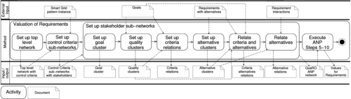
1. Set up top-level network. For the top-level we set up the goal cluster containing the goal “Overall best system.” The goal cluster is influenced by the control criteria cluster. For the control criteria, we stick to the BOCR criteria as suggested by Saaty (Saaty and Ozdemir, 2003). But nevertheless, it is possible to choose other strategic criteria here. Strategic criteria do not influence each other. Hence, for this network we have a hierarchy from the goal to the criteria (see Figure 4.9, upper left-hand side). For our example, we decide to use only benefits and costs (see Figure 4.10, left-hand side).
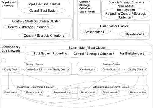

2. Set up control criteria sub-networks. For each control criterion we add a sub-network. A sub-network consists of a goal cluster with a goal like “Best system regarding benefits.” The goal cluster is influenced by a stakeholder cluster, which contains a node for each stakeholder of the system-to-be. We assume the stakeholders to be independent, because the goals a stakeholder wants to achieve are not based on the perception of these goals by other stakeholders. Thus, we do not have any inner dependence influence. For our example, we have the three stakeholders billing manager, Tesla Inc., and Consumer (see Figure 4.10, right-hand side).
3. Set up stakeholder sub-networks. The stakeholder sub-networks are the real ANP networks, while the top-level and control criteria level just serve for the integration of dimensions and views on the system-to-be. Hence, we split up the setup of stakeholder sub-networks into some sub-steps. Note that these steps directly apply for the benefits criterion. For other criteria they might have to be modified. For risk and opportunity the steps can be performed without modifications, but for costs, we removed the quality clusters and only introduced the clusters “fixed costs” and “running costs.” The resulting stakeholder sub-network for the Consumer regarding benefits is shown in Figure 4.11.
a. Set up goal cluster. Add a goal cluster containing a goal like “Best system for stakeholder A regarding control criterion C.” All top-level goals and their satisfaction level have an influence on the overall goal. Hence, the goal cluster is influenced by all other clusters except the alternative clusters. For our example, the top-level goals privacy, security, performance, and economy have an influence on the overall goal “Best system for Consumer regarding Benefits” (see Figure 4.11).
b. Set up quality cluster with criteria. For each top-level quality, such as performance, security, economy, or privacy, set up a cluster. Each cluster contains the leaf (hard goals/soft goals/tasks) of the goal model for a stakeholder as criteria. A cluster only contains those leaves that are a result of the decomposition of the corresponding top-level goal using and/or/makes/decomposition relations. For example, for the top-level goal “privacy” there is a decomposition path via “private data not disclosed,” “other parties don’t get data,” and “protect communicated private data” to “communicate confidentially” (see Figure 4.5). Hence, we add the criterion “communicate confidentially” to the privacy cluster (see Figure 4.11).
c. Set up criteria relations. For each helps/hurts relation of the goal model, add an influence relation between the corresponding criteria. Note that those goal relations are propagated down transitively from a parent goal, which is the target, to its sub-goals. We have to relate the privacy criterion “communicate confidentially” with the security criteria “bill not manipulated,” “consumption data not manipulated,” and “household not manipulated” (see Figure 4.11), because the goal “communicate confidentially” helps the top-level goal “security” (see Figure 4.5).
d. Set up alternative clusters. For each requirement, add a cluster containing the alternatives for this requirement as nodes. Note that for some ANP software having several clusters for alternatives is not allowed. In this case, merge them to one. This does not influence the outcome, only the comprehensibility. Figure 4.11 shows the alternative cluster (the cluster at the bottom). For superdecisions, the tool we use is the case that only one alternative cluster is allowed.
e. Relate criteria and alternatives. Relate the criteria of the quality clusters with the requirements that influence their fulfillment. Based on Figure 4.5, we relate “responsive user interface” with RQ25 and its alternatives, and we relate RQ5 with “analyze consumption data” and “verify consumption data.” For the stakeholder Consumer, there is no relation between a criterion and RQ4 or RQ24, because they are related to goals of Tesla Inc.
f. Relate alternatives. Relate the alternatives with other alternatives that have an impact on them. The alternatives for a requirement have to be related according to the relations of the original requirement. According to Table 4.8, we have to relate RQ11 and RQ24, as well as RQ24 and RQ25.

When the QuaRO-ANP-Network is set up, one can proceed with the regular ANP process starting with step 5 as described in Section 4.2.3. Example results for a valuation with ranking are shown in Figure 4.12. The first column of the table shows the total value (third column) in a graphical way. The second column contains the name of the alternative. The third column shows the value of the alternative with respect to ANP. The ranking column orders the alternatives with respect to the total column. Note that requirements having no alternatives always valuate to 0 (RQ4, RQ5).

From the rankings we see that the consumer prefers to be secured against a rather strong attacker, which is indicated by high values for RQ11 and RQ11.2, and low ones for RQ11.3 and RQ11.4 (see Figure 4.12a). As a trade-off, the consumer is willing to relax the setting in which the performance expectations are guaranteed, which is indicated by a high value for RQ25.4. The consumer does not care about the performance regarding the external request (RQ24–24.3). In contrast, Tesla is willing to relax the attacker strength and the performance setting for internal requests, which is indicated by high values for RQ11.4 and RQ25.4 (see Figure 4.12b). For the external requests, Tesla prefers the strongest requirement RQ24. For RQ24 the values are not very distributed, which is due to the fact that Tesla does care about the requirements from the consumer. Hence, Tesla did some compromise balancing while comparing the alternatives. But overall, we see that the two stakeholders, consumer and Tesla, have different preferences, especially regarding security. These different views are then synthesized into one value for each requirement (or alternative) using the different levels of the QuaRO-ANP-Network (see Figure 4.9). First, the different views of the stakeholder regarding one control criterion are aggregated using the “Control Criterion Sub-Network for Benefits” (see Figure 4.10, right-hand side). Then, the different control criteria are aggregated using the top-level network (see Figure 4.10, left-hand side). The aggregation of the different views of consumer, Tesla, and the billing manager, and the two dimensions benefits and costs, is almost identical to the preferences of Tesla. RQ11.4 is the first option for security, RQ24 for the performance of the external communication, and RQ25.4 for the internal communication (see Figure 4.12c compared to Figure 4.12b). This happens not due to a discrimination of the consumers’ wishes. When coming to costs, the consumer preferences change due to the increased costs for measurements against a strong attacker. Note that the billing manager has hardly any influence on the presented requirements. The only requirement the billing manager is concerned with is RQ24, and even for this requirement, the manager is not really interested in the performance setting. In the end, we get a meaningful ranking. Nevertheless, for RQ11 and RQ24 it is not as clear-cut as for RQ25.
4.7 Optimization of Requirements
In this step, all the requirements, their relations and the corresponding values are prepared in such a way that they can form the input to an optimization model. We describe the setup of the optimization model and how to transform the input information into the optimization model. Using the optimization model, it is possible to compute the optimal set of requirements regarding the optimization goals and the valuation of the requirements automatically.
The parameters of the optimization model are described in the following:
Parameters: Sets
| G = {G1, G2, …, Gz} | Set of goals | (15) |
| FR = {R1, R2, …, Ry} | Set of functional requirements | (16) |
| QR = {Q1, Q2, …, Qx} | Set of quality requirements | (17) |
| R = FR ∪ QR | Set of requirements | (18) |
Parameters: Relations/Value Coefficients
| Gi ∈ Gmust ∈ {0,1} | Determines whether a goal i has to be in the solution (1) or not (0) | (19) |
| Rk ∈ Rinitial ∈ {0,1} | Determines whether a requirement k is part of the initial set of requirements (1) or not (0) | (20) |
| Rk ∈ Rmust ∈ {0,1} | Determines whether a requirement k has to be in the solution (1) or not (0) | (21) |
| Rk ∈ Rvalue ∈ | Determines value of a requirement k | (22) |
| G2Gi,j ∈ Gand/or/xor ∈ {0,1} | Determines whether a goal j is sub-goal to goal i in an (AND/OR/XOR)-relation (1) or not (0) | (23) |
| G2Gi,j ∈ Gdeny ∈ {0,1} | Determines whether a goal j denies goal i (1) or not (0) | (24) |
| G2Ri ∈ G,k ∈ Rand/or/xor ∈ {0,1} | Determines whether a requirement k is required to fulfill goal i in an (AND/OR/XOR)-relation (1) or not (0) | (25) |
| R2Rk,l ∈ Rdeny ∈ {0,1} | Determines whether a requirement l denies requirement k (1) or not (0) | (26) |
| R2Rk ∈ FR,l ∈ QRcomplement ∈ {0,1} | Determines whether quality requirement l complements functional requirement k (1) or not (0) | (27) |
| R2Rk,l ∈ Ralternative ∈ {0,1} | Determines whether requirement l is an alternative for requirement k (1) or not (0) | (28) |
The inputs to this optimization model are the goal model with interactions (see Figure 4.5) and the requirements with interactions and alternatives (see Tables 4.8–4.10). The goals are collected in G. The information about AND, OR, XOR relations between goals is added to the corresponding coefficients G2Gand/or/xor. For the goal interactions, we only add the information about goals denying each other, using the coefficient G2Gdeny. The other positive or negative interactions are already considered when valuating a requirement using ANP. For the requirements, we capture the information about denying requirements in R2Rdeny, the information about complementing requirements in R2Rcomplement, and whether a requirement is an alternative for another requirement in R2Ralternative. If a goal or requirement has to be in the solution, is expressed using Gmust/Rmust. For the requirements we also model the information, if a requirement was already in the initial set of requirements or not using Rinitial. Last, we have to relate goals and requirements using G2Rand/or/xor.
Decision variables
| gi ∈ G ∈ {0,1} | Determines whether goal i is part of the solution (1) or not (0) | (29) |
| rk ∈ R ∈ {0,1} | Determines whether requirement k is part of the solution (1) or not (0) | (30) |
The target of our optimization is to minimize the difference between the initial set of requirements, which contains some unresolved conflicts but is ideal in the sense that all goals and requirements of each stakeholder are completely covered, and the compromise set of requirements, which contains no conflicts but relaxed original requirements or even excludes some goals and requirements. The solution is given with respect to the decision variables gi and rk, which indicate whether a goal or requirement is in the solution or not.
Target function
Minimize((∑k∈RRinitialk*Rvaluek)−(∑k∈Rrk*Rvaluek)) | Minimize difference between ideal solution with conflicts and compromise solution | (31) |
Note that the target function does not look like the regular form for MOO (see Section 4.2.4). Indeed, the target function only optimizes the values of the requirements. The reason is that we moved the aggregation of different objectives and stakeholders to ANP. Hence, the value for a requirement already reflects the views of different stakeholders on different dimensions, such as benefits and costs. As a result, we do a hidden MOO, regarding the target function. This simplifies the optimization, but a more fine-grained and detailed optimization model might produce even better results. This is a topic for future research.
Because the solution has to assure several properties, there are some constraints. For example, it is not allowed to have two requirements in the solution that deny each other. Another example is the property that a goal is only allowed in the solution if at least one parent is in the solution and it is fulfilled with respect to related sub-goals or requirements. All constraints are formulated in the following.
Constraints
| Assuresthatgoaliisinthesolutionwheneveritisamustgoal︷Gmusti−gi≤0∀i∈G | (32) |
gihastobe0ifanyothergoaldenyingitisinthesolution.Otherwisefreechoice.︷(1−j∈G∏(1−1ifjdeniesiandjisinthesolution︷(gj∗G2Gdenyi,j))︸1ifnogoaldenyingiisinsolution)∗gi=0∀i∈G | (33) |
gihastobe0ifanANDsub‐goalisnotinthesolution.Otherwisefreechoice.︷(1−j∈G∏1ifjisnotanANDsub‐goalofiorjisanANDsub‐goalandjisinthesolution︷((1−G2Gandi,j)+(G2Gandi,j∗gj))︸1ifallANDsub‐goalsareinthesolution)∗gi=0∀i∈G | (34) |
(1−0ifihasatleastoneORsub‐goal︷j∈G∏(1−G2Gori,j))∗(gi−SumofORsub‐goalsinthesolution︷∑j∈G(G2Gori,j∗gj))≤0︸giisfreetochoosewhenatleast1ORsub‐goalofiisinthesolution,otherwise0.∀i∈G | (35) |
(1−0ifihasatleastoneXORsub‐goal︷j∈G∏(1−G2Gxori,j))∗(gi∗(1−SumofXORsub‐goalsinthesolution︷∑j∈G(G2Gxori,j∗gj)))=0︸giisfreetochoosewhenexactly1XORsub‐goalofiisinthesolution,otherwise0.∀i∈G | (36) |
gihastobe0ifanANDrequirementisnotinthesolution.Otherwisefreechoice.︷(1−k∈R∏1ifkisnotanANDrequirementofiorkisanANDrequirementandinthesolution︷((1−G2Randi,k)+(G2Randi,k∗rk))︸1ifallANDrequirementsofiareinthesolution)∗gi=0∀i∈G | (37) |
(1−0ifihasatleastoneORrequirement︷k∈R∏(1−G2Rori,k))∗(gi−SumofORrequirementsinthesolution︷∑k∈R(G2Rori,k∗rk))≤0︸giisfreetochoosewhenatleast1ORrequirementofiisinthesolution,otherwise0.∀i∈G | (38) |
1ifihasatleastoneXORrequirement︷(1−k∈R∏(1−G2Rxori,k))∗(gi∗0ifoneXORrequirementisinthesolution︷(1−∑k∈R(G2Rxori,k∗rk)))≤0︸giisfreetochoosewhenexactly1XORrequirementofiisinthesolution,otherwise0.∀i∈G | (39) |
| Assuresthatarequirementkisinthesolution,whenitisamustrequirement︷Rmustk−rl≤0∀k∈R | (40) |
rkhastobe0ifanyotherrequirementdenyingitisinthesolution.Otherwisefreechoice.︷(1−l∈R∏(1−1ifldenieskandlisinthesolution︷(rl∗R2Rdenyk,l))︸1ifnorequirementdenyingkisinsolution)∗rk=0∀k∈R | (41) |
rkhastobe0ifanyotheralternativerequirementisinthesolution.Otherwisefreechoice.︷(1−l∈R∏(1−1iflisanalternativeforkandlisinthesolution︷(rl∗R2Ralternativek,l))︸1ifnorequirement,whichisanalternativefork,isinsolution)∗rk=0∀k∈R | (42) |
0ifkcomplementsnootherrequirement︷(1−l∈R∏(1−R2Rcomplementsl,k))∗(rk−Sumofcomplementrequirementsinthesolution︷∑l∈R(R2Rcomplementsl,k∗rl))≤0︸rkhastobe0ifnorequirementsitcomplementsisinthesolution.Otherwisefreechoice∀k∈R | (43) |
rkhastobe0ifnogoal,itisrelatedto,isinthesolution︷rk−∑i∈G(gi∗(G2Randi,k+G2Rori,k+G2Rxori,k))︸1ifiisinthesolutionandkisrelatedtoit.≤0∀k∈R | (44) |

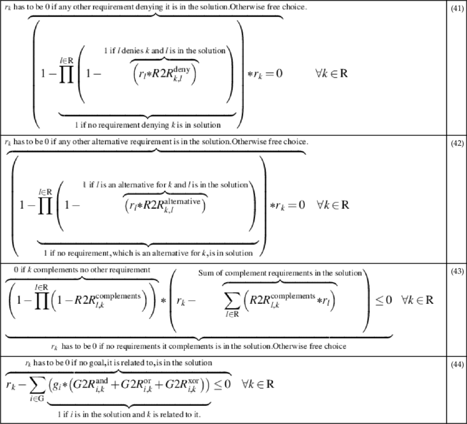
For the five requirements of our example, the solution is as follows. We used LP-Solve7 with the Zimpl8 plugin for solving the optimization. The optimizer selected RQ11.4 for the confidential communication, RQ24 for the performance of the external communication, and RQ25.4 for the performance of the internal communication. Both functional requirements RQ4 and RQ5 are also in the solution. Thus, every initial requirement is covered by itself or an alternative. Hence, all goals are also fulfilled.
The result looks somewhat trivial, because the optimization produces the same result as naively picking the requirements according to their ranks. But this is due to the nature of our example and the preferences. The alternatives preferred most for RQ11 and RQ25 are the most relaxed ones. Thus, the fulfillment of RQ24 is not a problem. But keeping in mind that for the full-use case, many more requirements have to be considered, it is not that easy any more. Then, a highly preferred requirement RQX might deny two other preferred (bus less preferred than RQX). Adding the two other requirements and replacing RQX by one of its alternatives might result in an overall better solution. Considering the goal tree the situation gets even more complicated. Whenever a goal is not satisfied, all of its sub-goals are also removed as long as they have no other parent. This also leads to a removal of the related requirements. Managing all of these goal and requirement interactions is hardly possible for a human for bigger scenarios. But using the optimization model, all balancing and managing of interactions is achieved automatically.
4.8 Related Work
For related work, we consider topics related to the steps of our QuaRO method, namely detection of requirements interactions, generation of requirements alternatives, valuation of requirements, and optimization of requirements, reflecting the references at the bottom of each step of the QuaRO method given in Figure 4.1. Additionally, we discuss work in the field of smart metering.
Egyed and Grünbacher (2004) introduce an approach to identify conflicts and cooperations among requirements based on software quality attributes and dependencies between requirements. After categorizing requirements into software attributes such as security, usability, etc. manually, the authors identify conflicts and cooperations between requirements using dependencies among requirements. In a final step, they filter out requirements, the quality attributes of which are conflicting, but there is no trace dependency among them. Our method is similar to this method in a sense that both methods rely on dependencies between requirements. We make use of the existing problem diagrams to find the dependencies by taking the constrained domains into account.
As opposed to our problem-driven method, Hausmann et al. (2002) introduce a use-case-driven approach to detect potential consistency problems between functional requirements. A rule-based specification of pre- and post-conditions is proposed to express functional requirements. The requirements are then formalized in terms of graph transformations. Conflict detection is based on the idea of independence of graph transformations. In contrast to our method for detecting interactions among quality requirements, this approach detects interactions between functional requirements.
Lamsweerde et al. (1998) use different formal techniques for detecting conflicts among goals based on KAOS. One technique to detect conflicts is deriving boundary conditions by backward chaining. Every precondition yields a boundary condition. The other technique is selecting a matching generic pattern. The authors provide no tool support. Additionally, they elicit the domain knowledge relatively late, namely during the conflict analysis and not before as it is the case in our method.
Mylopoulos et al. (2001) propose a goal-oriented analysis to explore and evaluate alternatives for achieving a goal with regard to its objectives (softgoals). The authors first decompose functional goals into and/or hierarchies and quality goals into softgoal hierarchies. Next, they correlate the goals with all the softgoals in order to use this correlation for comparison and evaluation of goals later on. Subsequently, the authors select a set of goals and softgoals that meets all functional goals and best satisfies softgoals. In contrast to our approach, the softgoals (quality requirements) analysis is not performed with regard to the goals (functional requirements).
Elahi and Yu (2012) present work on comparing alternatives for analyzing requirements trade-offs. They start by modeling the goals in i* to determine the important properties for deciding which solution should be selected. Then they propose a pairwise elimination of alternatives using the Even Swaps method. Our approach is different, because Elahi and Yu only compare complete systems as alternatives. Hence, they do not propose a method for requirements reconciliation but solution picking. And Even Swaps is not preferable whenever one has many alternatives or goals (Mustajoki and Hämäläinen, 2007).
Ernst et al. (2010) propose a method for reasoning about optional and preferred requirements. First. they model the requirements using goal graphs. Then they use a SAT solver to compute all possible goal graphs, which contain no interactions and satisfy the mandatory goals. Then they eliminate some of the generated solutions using a dominance decision strategy. As an alternative, they propose a method using tabu search and solution pruning for improving the runtime of executing their method. However, using that alternative no longer guarantees optimality. In contrast, our approach guarantees optimality, because no solution is discarded. Moreover, we always identify one solution, whereas the dominance approach is so strict that sometimes no solution can be removed from the set of possible solutions. Thus, the decision problem might not be solved.
Lang et al. (2008) present an optimization model for the selection of services according to customers’ needs. Needs are represented as business processes that have to be supported by service selection. The optimization takes communication costs, platform costs, and a monetarized utility value into consideration. Hence, Lang et al. only do an optimization for functional requirements, indirectly expressed by the process, and they do not target services to be developed but only existing ones.
Stegelmann and Kesdogan (2012) treat privacy issues in the context of smart metering. The basis of the analysis is the protection profile (Kreutzmann et al., 2011); we also used in this work. They propose a security architecture and a non-trusted k-anonymity service. In contrast to our work, Stegelmann and Kesdogan only consider privacy issues and do not attempt to reconcile these with other quality requirements.
4.9 Conclusions and Perspectives
In this chapter, we have presented a comprehensive method to systematically deal with quality requirements. In particular, we give guidance how to
− find interactions involving quality requirements.
− relax quality requirements in order to ameliorate requirements interactions.
− use the relaxations to generate requirements alternatives.
− valuate requirements (and alternatives) according to stakeholders’ preferences.
− obtain an optimal set of requirements to be implemented.
In the different steps of the QuaRO method, we bring together a number of established techniques and show how they can be applied together in an advantageous way. In particular, we combine goal- and problem-based requirements engineering methods, UML, ANP, and optimization techniques. The steps of the QuaRO method provide the “glue” between the different techniques.
Distinguishing features of our method are that it (i) explicitly takes into account different stakeholders with possibly conflicting interests and (ii) explicitly models the environment in which the software to be built will be operating. Using domain knowledge is crucial for adequately dealing with quality requirements. In contrast to other work, we remain in the problem space when expressing domain knowledge and do not yet consider possible solutions for quality requirements.
While for the smart grid example we deal with security and performance, of course our method is applicable to other quality requirements for which a UML profile, relaxation templates, etc. should be defined. Using our method, we obtain a set of requirements that satisfies the different stakeholders’ goals to the largest possible extent. Those requirements are modeled in such a detailed way that they are an excellent starting point for the design of the software to be built.
In the future, we plan to elaborate further on the different steps of the QuaRO method, to provide an extension for our general approach to take into account further phases of software development, and to provide tool support for its application. As far as the refinement of the QuaRO method is concerned, we intend to further develop the requirements interaction method so as to obtain as few interaction candidates as possible. Furthermore, we want to elaborate more fine-grained optimization models and also investigate different optimization approaches. Considering uncertainty in the optimization process is another worthwhile goal, as well as developing strategies to minimize the number of comparisons needed for ANP.
Concerning the connection of the QuaRO method with further phases of software development, we plan to explicitly support the twin peaks model. Here, requirements are supposed to be the architectural drivers, whereas decisions made in the architectural phase might constrain the achievement of initial requirements, thus changing them. Such feedback loops should be supported by methods and tools.
As far as tool support is concerned, we envisage an integrated tool chain based on the UML4PF tool. The tool support reduces the complexity of the method for practical application. The envisaged tool should support the requirements engineer in applying the QuaRO method. In particular, the step “detection of interactions” can be performed automatically, using the information contained in the problem diagrams. The steps “generation of alternatives” and “valuation of requirements” are planned to be interactive involving stakeholders to exclude inappropriate alternatives and to compare different alternatives for valuation. We can then transform the input information contained in the model to compute the optimal set of requirements automatically using the optimization model.