Archample—Architectural Analysis Approach for Multiple Product Line Engineering
Bedir Tekinerdogan1; Özgü Özköse Erdoğan2; Onur Aktuğ2 1 Bilkent University, Ankara, Turkey
2 Aselsan, Ankara, Turkey
Abstract
The increased size and complexity of software systems has led to the notion of multiple software product lines (MPLs) in which products are composed from subproducts in separate software product lines. Thus, it is important to identify the proper architectural decomposition of the MPL with respect to the stakeholders’ concerns before large organizational resources are committed to the development. Designing MPL architectures is challenging due to the higher level of abstraction and the integration of different product lines. Different architecture analysis approaches have been introduced, but none of these focuses on the evaluation of MPL architectures. We propose the architecture analysis approach for MPL Engineering (Archample), which has been particularly defined for the analysis of MPL architectures. Archample also introduces architectural viewpoints for modeling and documenting MPL and likewise supporting the analysis of the decomposition of an MPL architecture. The approach has been designed and validated within a real industrial context of Aselsan REHİS Group (Aselsan REHİS), a leading high-technology company in defense systems development in Turkey.
Software product line engineering
Multiple product line engineering
Software architecture viewpoint
Software architecture analysis
Acknowledgments
We would like to thank Levent Alkışlar, Baki Demirel, Hakime Koç, Gökhan Kahraman, Şafak Şeker, Ümit Demir, and Hakan Bali for earlier discussions on the RadEW product line architecture. This work has been carried out as part of the Product Line Engineering for Radar Electronic Support System (PLE-RES) project under the responsibility of Aselsan REHİS and Bilkent University.
Introduction
The benefits of adopting a product line (PL) approach has been analyzed and discussed before (Babar et al., 2004; Clements and Northrop, 2002; Pohl et al., 2005; Schmid and Verlage, 2002). The key motivation for adopting a PL engineering process is to develop products more efficiently, get them to the market faster to stay competitive, and produce with higher quality (Schmid and Verlage, 2002). In alignment with these goals, different software product line (SPL) engineering processes have been proposed, and an increasing number of companies aim to adopt a PL engineering approach.
The latest trends show that the reuse scale of current PL approaches seems to increase further with the increased size and complexity of applications that the industry is using. In this context, several authors have indicated the need for multiple product lines (MPLs) in which a product is defined as a composition of products from different PLs (Aoyama et al., 2003; Archer et al., 2010). Examples of MPL have been provided in the domains of e-government (Aoyama et al., 2003), car manufacturing (Hartmann et al., 2009), and healthcare (van der Linden and Wijnstra, 2001). The MPL architecture represents the gross-level structure of the system consisting of subproducts derived from separate PLs, which together form the overall product. An MPL architecture can be considered as a system-of-systems architecture that defines the systemic design decisions beyond flat PLs and likewise will have a serious impact on the overall system development.
Hence, it is important that the MPL architecture supports the software system qualities required by the stakeholders.
Architecture analysis approaches have been broadly discussed in the literature, and different methods have been proposed (Babar et al., 2004; Dobrica and Niemela, 2002; Kazman et al., 2005; Tekinerdogan et al., 2004). The goal of software architecture analysis methods is usually to understand the consequences of architectural decisions with respect to the system’s quality attribute requirements and with respect to the tradeoffs between them (Babar et al., 2004; Roy and Graham, 2008; Dobrica and Niemela, 2002). Current architecture analysis approaches tend to focus on single-system architecture and appear to be limited for addressing the larger granularity and abstraction level of MPL architecture. We propose the so-called Archample approach for the analysis of architecture within the MPL engineering context. Unlike existing architecture analysis approaches, Archample focuses on the analysis of MPL architecture in particular. The goal of Archample is to support the decision on whether to use an MPL architecture and likewise evaluate different alternative decompositions of the MPL architecture. Archample also introduces architectural viewpoints for modeling and documenting MPLs and likewise supporting the analysis of the decomposition of an MPL architecture. We illustrate the analysis of alternative MPL architectures for radar and electronic warfare systems in the context of Aselsan in Turkey (Aselsan, 2011). Aselsan is a leading high-technology company in defense systems development introducing state-of-the-art equipment and software-intensive system solutions for both sophisticated military and professional applications. Using the viewpoints as defined in Archample, we describe the analysis of four important architecture decomposition alternatives for MPLs in Aselsan REHİS. Our study and experiences show that for analyzing the architecture of MPLs, it is necessary to describe these using appropriate architectural viewpoints. With the viewpoints we have introduced, we could describe the MPLs in a more proper way, communicate the design decisions, and select a feasible design alternative.
The remainder of the chapter is organized as follows. In Section 10.1, we describe the background including MPL engineering and software architecture analysis methods. In Section 10.2, the case study of radar and electronic warfare systems is described. In Section 10.3, we describe the architecture viewpoints for MPLs. Section 10.4 presents the Archample method using the introduced viewpoints. Section 10.5 describes the application of Archample to the industrial case study. Section 10.6 presents the related work and characterizes Archample with respect to the architecture evaluation frameworks in the literature. Finally, Section 10.7 concludes the paper.
10.1 Background
10.1.1 Multiple product line engineering
According to ISO/IEC 42010 (ISO/IEC, 2007), the notion of system can be defined as a set of components that accomplishes a specific function or set of functions. Each system has an architecture, which is defined as “the fundamental organization of a system embodied in its components, their relationships to each other, and to the environment, and the principles guiding its design and evolution.” When reuse is an important concern, a system can be built based on the PL approach. For very large systems, the scope of the PL can be extended further, and the product can be built using subproducts from MPLs. The notion of MPLs has been addressed earlier by different authors including Aoyama et al. (2003), Archer et al. (2010), Fritsch and Hahn (2004), van der Linden and Wijnstra (2001), van Ommering (2002), and Rosenmüller and Siegmund (2010). In this context, the terms MPLs, nested PLs, or PLs of PLs have been used to denote the same concept. Rosenmüller and Siegmund (2010) define MPLs as “a set of interacting and interdependent SPLs.”
In principle, we can consider the composition of PLs as the application of a composite pattern as shown in Figure 10.1. PL could be either a flat SPL or a Composite Product Line (CPL). CPL itself could contain other PLs; likewise, the PL can be built in a nested manner. Alternatively, the CPL could include only flat PLs, leading to an MPL consisting of independent PLs. In each CPL the separate PLs could use other PLs. A PL (CPL or PL) can include other reusable assets that are not PLs themselves (e.g., libraries).

The pattern in Figure 10.1 appears to be general and can model different configurations of MPLs. It should be noted that each PL is defined by a two-life cycle process including domain engineering (with product management) and application engineering. Based on these two separate processes, the notion of architecture is usually specialized into a PL architecture and an application architecture (Pohl et al., 2005). A PL architecture represents the common and variant structures of a set of products of the selected PL; an application architecture represents the architecture of a single system. The architects who define these architectures can be called PL architects and application architects.
10.1.2 Software architecture analysis methods
The architecture forms one of the key artifacts in the entire software development life cycle because it embodies the earliest design decisions and includes the gross-level components that directly impact the subsequent analysis, design, and implementation. The key concerns of an architecture are defined by stakeholders: an individual, team, or organization with interests in, or concerns relative to, a system. Each of the stakeholder’s concerns impacts the early design decisions that the architect makes. As architecture is critical for the success of a project, different architectural evaluation approaches have been introduced to evaluate the stakeholders’ concerns. A comprehensive overview and comparison of architecture analysis methods have been given by, for example, Dobrica and Niemela (2002) and Babar et al. (2004). Kazman et al. (2005) have provided a set of criteria for comparing the foundations underlying different methods, the effectiveness, and usability of methods.
Figure 10.2 provides a conceptual model that we have defined to describe the architecture evaluation approach. Although different architecture evaluation approaches have been proposed in the literature, we can state that most of these follow the model in Figure 10.2. In essence, each architecture evaluation approach takes as input stakeholder concerns, environmental issues, and architecture description. Based on these inputs, the evaluation results in an Architecture Evaluation Report, which is used to adapt the architecture.

The proposed architecture evaluation approaches usually differ with respect to, for example, the goal of the approach, the type of inputs, the evaluation techniques, the addressed quality attributes, the stakeholders’ involvement, the ordering of activities, and the output results (Babar et al., 2004; Kazman et al., 2005). It appears that no explicit approach seems to have been provided to analyze architecture within an MPL engineering context. In the following sections we show the need for a specific analysis approach for MPL engineering and the relation to the existing architecture analysis approaches.
10.2 Case Description
Figure 10.3 shows the layered reference architecture for radar and electronic warfare systems as defined in the so-called REFoRM project at Aselsan REHİS. For confidentiality reasons, the details of each layer are not given. REFoRM consists of three basic layers: Mission Domain Applications, Application Support Services, and Application Platform Cross Domain Services. These layers include different subsystems for Radar, Radar Electronic Warfare, Communication Electronic Warfare, and Self-Protection. A Radar Electronic Support system is basically an example of the Mission Domain Application. A typically product is configured by selecting different subsystems in the three distinct but interdependent layers.

Obviously, most products that Aselsan REHİS develops share lots of commonality; likewise, Aselsan REHİS has focused on systematic reuse based on PL engineering. The primary business drivers here are a faster time-to-market, higher quality, and overall cost reduction. Given that products are developed using the reference architecture in Figure 10.3, one could argue that this complete domain represents one PL. Yet, experience showed that this is far from trivial and to a large extent not feasible. Although the products are developed using the reference architecture, the separate subsystems represent different domains (Radar, Radar Electronic Warfare, Communication Electronic Warfare, and Self-Protection), are actually realized in different business groups, and as such could be considered as products derived from different product families. On the other hand, defining a PL for each (sub-)domain will increase the complexity and impede the management of the PL activities. The observation that the entire system actually consists of separate interacting product families leads to the problem of finding the right decomposition of the system into product families. For this, it is important to identify the right set and boundaries of PLs, analyze the different decomposition alternatives, and select a feasible decomposition.
10.3 MPL Architecture Viewpoints
Defining the proper configuration of MPLs is not trivial. To support the analysis of the MPL, first a proper documentation of the MPL architecture is required. A common practice for describing the architecture according to the stakeholders’ concerns is to model different architectural views (Clements et al., 2011). An architectural view is a representation of a set of system elements and relations associated with them to support a particular concern. Usually multiple architectural views are needed to separate the concerns and as such support the modeling, understanding, communication, and analysis of the software architecture for different stakeholders. Architectural views conform to viewpoints that represent the conventions for constructing and using a view. Existing viewpoints for architecture (e.g., such as defined in Clements et al., 2011) can be applied to present architectural descriptions for both PL architecture and application architecture. However, if we consider MPLs, it appears that plain usage of existing viewpoints is not sufficient to represent the design and interaction of the different PLs. For reasoning about MPL decomposition, it is important make an explicit distinction among CPLs and single PLs and represent the interaction among the different PLs. This is necessary for supporting the understanding and communication among the stakeholders, the analysis of the PL decomposition, and the guidance of the product development. To cope with this issue, complementary to existing viewpoints in the literature, we define two architectural viewpoints for MPLs, the PL Decomposition Viewpoint (Table 10.1) and PL Dependency Viewpoint (not shown). We have defined these viewpoints because we are particularly interested in the composition and interaction of the PLs. To define the viewpoints, we have adopted the guidelines of the recommended standard for architecture description (ISO/IEC, 2007).
Table 10.1
Product Line Decomposition Viewpoint
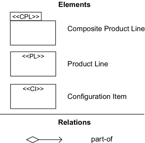
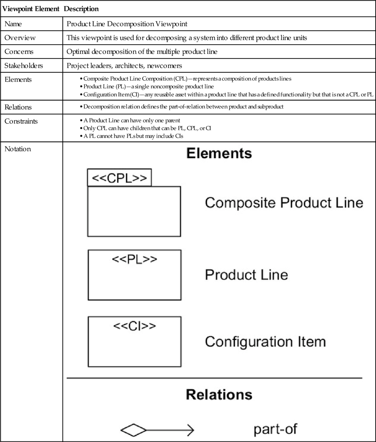
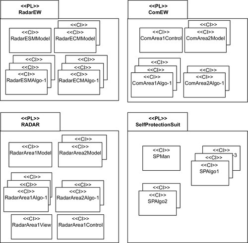
Based on the conceptual model as defined in Figure 10.1, both viewpoints distinguish between three types of development units: CPL, PL, and Configuration Item (CI). A CPL is defined as a composition of PLs or other CPLs. A PL cannot include other PLs. Both a PL and CPL are defined in fact as subsystems (Clements et al., 2011). A subsystem is defined as part of a system that “(1) carries out a functionally cohesive subset of the overall system’s mission, (2) can be executed independently, and (3) can be developed and deployed incrementally.” From this perspective, a CI is part of the system that cannot be considered as a subsystem that is either a CPL or PL, and it comprises the reusable assets within a CPL or PL. An example of a CI is a reusable unit that is part of the system, has a cohesive functionality, but cannot be executed independently. As it can be noted, we have chosen not to specify a separate notation for defining the composition of CIs. For this, we use the package construct of UML.
Figure 10.4 represents an example of the product line decomposition view for the given case study that is based on the viewpoint as shown in Table 10.1. Here, the system has been defined as one CPL that contains 3 separate CPLs (RadEW, ComEW, and Radar), 4 PLs (HASP, VERY, Navigation, and SelfProtectionSuite), and 12 CIs (libraries). The CPLs each consist of two PLs. The MPL architecture consists thus of four separate PL units (HASP, VERY, Navigation, and SelfProtectionSuite) and six other PLs that are nested in CPLs (RadarESM, RadarECM, ComArea1, ComArea2, RadarArea1, and RadarArea2). Each of these PLs will have its own domain engineering process and application engineering process. Variability management and modeling is applied within each PL. The dependency relations among different PLs are defined in the CPLs that compose the PLs.

In addition to showing the decomposition relations, it is also important to show the interactions among the PLs. For this we have defined the PL Dependency Viewpoint. This viewpoint adopts the same elements as the PL Decomposition Viewpoint but defines the uses relation. A PL unit uses another PL unit if its correctness depends on the correctness of the other. In fact, the relation is similar to the uses relation as defined in the Uses Style in the Views and Beyond approach (Clements et al., 2011). The difference is that the relation applies to a complete PL unit instead of implementation units. Further, if one PL unit uses another, there is usually also a configuration dependency. That is, the selection of features in one PL unit will have an impact on the selection of features in the other (Rosenmüller et al., 2008).
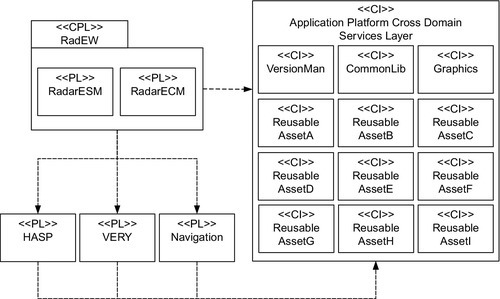
Figure 10.5 shows an example of the PL Dependency View that conforms to this viewpoint. Here, the dependency relations are shown using dotted arrows. Dependency relation here indicates the correct functioning of the dependent PL. As shown in the figure, the CPL RadEW uses the CIs, reusable assets, in the Application Platform Cross Domain Services Layer. Further, RadEW uses the product lines PL, VERY, and Navigation. Each of these PLs also uses the CIs from the Application Platform Cross Domain Services Layer. Note that the structure of the PL dependency view in Figure 10.5 follows the structure of the reference architecture of Figure 10.3.
10.4 Archample Method
The activities of the Archample approach are shown in Figure 10.6. As the figure shows, Archample consists of four phases: Preparation, Design Documentation, Evaluation, and Reporting. Archample is performed by a set of key stakeholders:
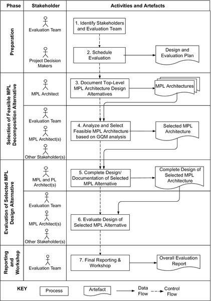
• Project decision makers: People interested in the result of the evaluation and who can affect the project’s directions. These decision makers are usually the project managers.
• MPL architect: A person or team responsible for design of the MPL architecture and the coordination of the design of the subarchitecture.
• PL architect: A person or team responsible for design of a single PL architecture. The single PL architect typically informs the MPL architect about the results and if needed also adapts the architecture to fit the overall architecture.
• Architecture stakeholders: Developers, testers, integrators, maintainers, performance engineers, users, builders of systems interacting with the one under consideration, and others.
• MPL architecture evaluator(s): A person or team responsible for the evaluation of the MPL architecture as well as the coordination of the evaluation of the PL architectures.
• PL architecture evaluator(s): A person or team responsible for the evaluation of the PL architecture as well as the coordination of the evaluation of the MPL architectures.
In principle, all these stakeholders may apply to both viewpoints in the previous section. In the following subsections, we elaborate on each phase of the method.
10.4.1 Preparation phase
During the Preparation Phase, first the stakeholders and the evaluation team (step 1) are selected. The stakeholders are typically a subset of the stakeholders (including project decision makers) listed above. After the stakeholders are selected, the schedule for evaluation is planned (step 2). In general, the complete evaluation of the MPL will take more time than for a single architecture evaluation. Hence, for defining the schedule a larger timeframe than usual is adopted.
10.4.2 Selection of feasible MPL decomposition
In this phase the different MPL architecture design alternatives are provided (step 3), and the feasible alternative is selected (step 4). The MPL alternatives are described using the MPL decomposition and uses viewpoints. Representation of the MPL architecture in step 3 is necessary to ensure that the proper input is provided to the analysis in step 4. At this stage, no detailed design of the MPL is necessary. This is because designing an MPL is a time-consuming process. Only after the feasible decomposition is found in step 4 will the design documentation be completed in step 5.
For the selection of the feasible PL architecture in step 4 we adopt the Goal-Question-Metric (GQM) approach, a measurement model promoted by Basili and others (Roy and Graham, 2008). The GQM approach is based upon the assumption that for an organization to measure in a purposeful way, the goals of the projects need to be specified first. Subsequently, a set of questions must be defined for each goal, and finally a set of metrics associated with each question is defined to answer each one in a measurable way. For applying the GQM, usually a six-step process is recommended where the first three steps are about using business goals to drive the identification of the right metrics, and the last three steps are about gathering the measurement data and making effective use of the measurement results to drive decision making and improvements. The six steps are usually defined as follows (Roy and Graham, 2008; Solingen and Berghout, 1999):
1. Develop a set of corporate, division, and project business goals and associated measurement goals for productivity and quality.
2. Generate questions (based on models) that define those goals as completely as possible in a quantifiable way.
3. Specify the measures needed to be collected to answer those questions and track process and product conformance to the goals.
4. Develop mechanisms for data collection.
5. Collect, validate, and analyze the data in real time to provide feedback to projects for corrective action.
6. Analyze the data in a post mortem fashion to assess conformance to the goals and to make recommendations for future improvements.
10.4.3 Evaluation of selected MPL design alternative
Step 4 focuses on selecting a feasible MPL decomposition alternative. An MPL consists of several PLs and thus multiple architectures. Likewise, in step 5 of Archample, we focus on refined analysis of the selected MPL alternative. In fact, the selected alternative can be a single PL architecture or different MPL architectures. In case the alternative is a CPL, we apply a staged-evaluation approach in which the MPL units (PLs or CPLs) are recursively evaluated. From this perspective, we distinguish among the following two types of evaluations: (a) top-down product evaluations and (b) bottom-up product evaluations.
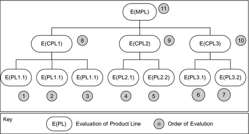
In the top-down evaluation, first the higher level PLs are evaluated. This is illustrated in Figure 10.7. Here, the evaluation order is indicated through the numbers in the filled circles. The evaluation starts with evaluation the top-level decomposition of the MPL architecture and continues with the subelements of the MPL, which can be again CPL or single PL.

In the bottom-up approach first the leaf PLs are evaluated, then the higher level architectures. An example bottom-up specialization is shown in Figure 10.8. Obviously, other hybrid specialization approaches that fall between top-down and bottom-up strategy can be applied. The selection of the particular evaluation strategy (top-down, bottom-up, or hybrid) depends on the particular constraints and requirements of the project. A hybrid approach can be preferred by considering the dependency relations among PLs, which are modeled in the PL dependency view.
The evaluation of the architecture can be done using any architecture evaluation method (including GQM again). Over the last decade several different architecture analysis approaches have been proposed to analyze candidate architectures with respect to desired quality attributes (Babar et al., 2004; Dobrica and Niemela, 2002; Kazman et al., 2005). The architecture evaluation methods can be categorized in different ways. Early evaluation methods evaluate the architecture before its implementation while late architecture evaluation methods require the implementation to perform the evaluation. In principle, within Archample we do not restrict the selection of any method.
10.4.4 Reporting and workshop
In the last phase of Archample, a report of the evaluation results is provided and a workshop with the stakeholders is organized. The stakeholders are typically a subset of the list as defined in Section 10.4. A template for the report is given in Table 10.2.
Table 10.2
Outline of the Final Evaluation Report
| Chapter 1 | Introduction |
| Chapter 2 | Archample Overview |
| Chapter 3 | Context and Business Drivers |
| Chapter 4 | MPL Architecture Alternatives |
| Chapter 5 | GQM Analysis of MPL Alternatives |
| Chapter 6 | Architecture Documentation of Selected Alternative |
| Chapter 7 | Evaluation of Selected Alternative |
| Chapter 8 | Overall Recommendations |
| Chapter 9 | Conclusion |
| Appendix |
The first Chapters 1–3 of the report provide the background information about the company and its business goals and describe the Archample method. Chapter 4 defines the different MPL architecture alternatives. Chapter 5 analyzes the MPL design alternatives and selects a feasible alternative. Chapter 6 presents the documentation of the selected alternative. In Chapter 7, the evaluation of the alternative is described using staged-evaluation approach (top-down, bottom-up, hybrid) and the evaluation results. Chapter 8 presents the overall recommendations, and Chapter 9 concludes the report. An appendix can consist of several sections and include, for example, the glossary for the project, explanation about standards, viewpoints, or other pertinent factors. After the first complete draft of the report, a workshop is organized to discuss the results. The discussions during the workshop are used to adapt the report and define the final version.
10.5 Applying Archample Within an Industrial Context
In the following subsections, we describe the application of Archample to the REFoRM project within Aselsan REHİS.
10.5.1 Preparation phase
In this phase, we identified the stakeholders and the evaluation team(s) as defined in Section 10.4. These included the project decision makers, three MPL architects, a PL architect for each PL, PL evaluation team, and other stakeholders required for each PL (such as developers, testers, and customers).
10.5.2 Selection of feasible MPL decomposition
Within the REFoRM project of Aselsan REHİS four different MPL architecture alternatives were identified:
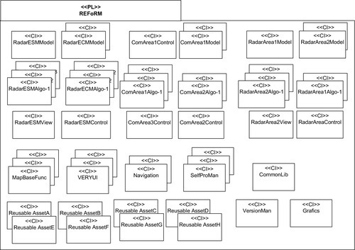
1. One PL: Defining the system as one PL as shown in Figure 10.9.
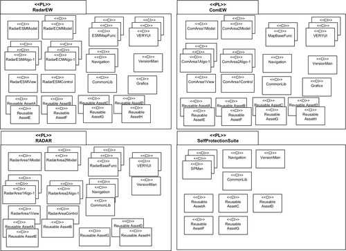
2. Four PLs: Defining the system as four independent PLs as shown in Figure 10.10.
3. AD PLs: Defining only the application domains as PLs as shown in Figure 10.11.
4. CPLs: Defining a CPL as it was shown earlier in Figure 10.4.
Before the analysis, the MPL architecture was not designed using the viewpoints as defined in Section 10.3. Thus, we took some time to provide a proper design of each alternative.
Evaluating four different alternatives using the GQM evaluation approach, as part of Archample, was carried out. Table 10.3 shows the GQM results as defined during the evaluation. The goals represent high-level business goals that were found important from the project decision makers. These goals are listed below:
Table 10.3
GQM Results for the Top-Level MPL Architecture in the REFoRM Project
| Goal | Questions | Metric |
| Optimize Reuse | What is the reuse level of assets? | # % of reused assets per product |
| What is the distribution over products for reused assets? | #asset distribution over products | |
| Is there overlapping functionality among PLs? | #common features over assets (in multiple PLs) | |
| Increase Productivity | What is the required manpower for the domain engineering activities? | #man month per PL |
| What is the required manpower for the application engineering activities? | #man month per application | |
| Manage Complexity | What is the complexity of commonality and variability? Are the domain boundaries properly defined and separated over PLs? Does each PL address a single domain (separation of domains over PLs)? | #depth of feature diagram #features #PL per Domain #Domain per PL |
| Ease organizational management | What is the structure of the required product line organization? Are the teams properly defined and separated over domain PL activities? Are the PL activities properly mapped to organization teams? | Organization Hierarchy Depth |
| Ease Product Line Management | What is the effort to add/remove/update product features within PL? | #man month for total maintenance activities per PL |
| What is the effort to add/remove/update product features across PLs? | #man month for total maintenance activities per CPL | |
| Can the organization structure cope easily when new products/domains are added? | Subjective evaluation by project management | |
| Ease Composition of Products | What is the effort for composing products from different PLs? | Subjective evaluation by project management |
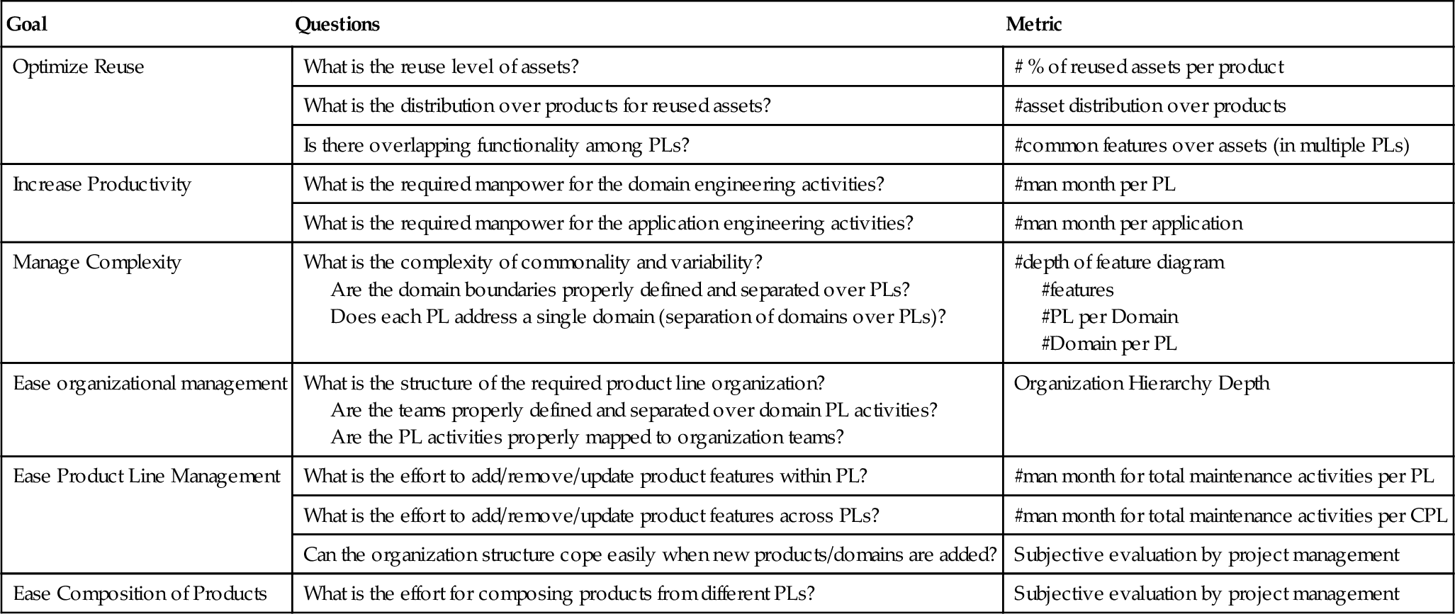
– Optimize Reuse: MPL architecture should supply maximum reuse within radar and electronic warfare projects; no functionality should be repeated in different PLs.
– Increase Productivity: The MPL architecture should need minimum manpower. Where possible the need for hiring new personnel should be minimized.
– Manage Complexity: Due to the large domain and huge sets of features, the complexity of variability management of the PL is very high. MPL architecture should help to cope with this complexity.
– Ease Organizational Management: Aselsan is working in well-defined domains and internal business units are currently organized around these units. The MPL architecture should be in alignment with these domains and not disrupt the structure too much.
– Ease PL Management: It should be easy to add/remove/update product features within and across business units. Also, the evolution of MPL architecture should be manageable.
– Ease Composition of Products: The PL decomposition should enable combinations of products from different domains managed by related business units in the company.
Once the goals, questions, and metrics were defined, we could start the actual evaluation. The result of the evaluation of each of the four alternatives according to the presented goals is shown in Table 10.4. It was decided that all the six goals should have equal weight. For each criterion the evaluation scale includes the values − −, −, +−, ++, and ++, defining a very negative evaluation to a very positive evaluation. The goals were evaluated with respect to the corresponding questions and the metrics. Below, we provide a short discussion of the alternatives.
Table 10.4
Evaluation Matrix for Design Alternatives of the Product Line Decomposition
| Goals |  One PL | Four PLs |  AD PLs | 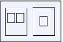 CPLs |
| Optimize Reuse | ++ | − − | −(−) | ++ |
| Increase Productivity | +(+) | − | − | ++ |
| Manage Complexity | − − | + | + | + |
| Ease Organizational Management | − − | ++ | ++ | +− |
| Ease Product Line Management | +(+) | + | − − | ++ |
| Ease Composition of Products | +(+) | − − | − | ++ |

1. One PL: As shown in Table 10.4, defining the system as one complete PL (Figure 10.9) is not favorable from the complexity management perspective and the ability to manage the organization for the resulting very large PL. In addition, the Mission Domain Applications level of the system was currently defined across different departments and from an organization point of view. Putting all the product divisions together was considered not feasible. On the other hand, this alternative was valued as positive because it would probably not include overlapping functionality, and the manpower needed would be optimized. Further, this alternative would also be beneficial for managing products and composing new products.
2. Four PLs: The second alternative of defining the system as four independent PLs (Figure 10.10) has been positively evaluated with respect to alignment with the domains because it supports the four Mission Domain Applications level. The organization management would also be distributed over the multiple divisions, thus the problems of a heavy central organization would be avoided. The product management would be easy but the composition of new products across MPLs would be severely impeded. Moreover, this alternative required that the different alternative PLs include development of similar functionality, and due to the overlapping functionality, reuse would not be optimized. Consequently, this alternative would also require more additional manpower than the other alternatives.
3. AD PLs: The third alternative (Figure 10.11) is the MPL with four separate PLs for the Mission Domain Applications level and an additional platform layer with reusable assets as libraries. For the first four criteria this alternative was evaluated like the second alternative. The motivations for the evaluations were also similar. In contrast to the second alternative, this alternative is not considered feasible for product management. The reason for this is that some critical domains are not developed as PLs but remain as libraries whose variability and architecture were not defined. Thus the composition of new products will be impeded. Regarding complexity of variability management, this was considered also similar to the second alternative. There will be less variability in the four domains because part of the functionality will reside in libraries. On the other hand, new variations would be harder to define.
4. CPLs: Defining the system as a CPL (Figure 10.4) was positively evaluated for almost all the defined criteria. The MPL could on the one hand include a hierarchical structure while still keeping the separation of domains and organizational management in the company. Overlapping functionality could be reduced or eliminated. Due to the hierarchical and composite structure, the development of new products would be supported. The only neutral result for this choice is the optimization of manpower; the manpower needed to develop the assets would be optimized as the reuse is optimized, but the manpower needed for the management of the PLs will be higher than a single PL because each PL and the CPL will need separate management.
From Table 10.4, it can be observed that defining “four PLs” and “application domain PLs” are the worst choices because they have the most negatives. Despite the increased management complexity in the PL, the alternative with one PL was more positively evaluated than was expected. After careful thought and discussion with the stakeholders, the most feasible alternative for the Aselsan REHİS case was determined to be the composite MPL alternatives. It should be noted that the evaluation of each of the alternatives was actually only possible after modeling each alternative using the architectural viewpoints in the previous section. Without the explicit architectural views, one had to rely on discussions, informal sketches, or feature modeling approaches. None of these were considered as powerful as explicitly documenting the architectural views.
10.5.3 Evaluation of the selected MPL design alternative
After the composite MPL was selected as the most feasible design alternative, the refined evaluation was necessary to evaluate the PL architectures in the MPL. For the refined evaluation, we adopted a top-down evaluation strategy. That is, we decided to analyze the top-level MPL first and then the sub-PLs. For some PLs it was decided not to perform an evaluation yet due to the time constraints. The strategy together with the selected evaluation methods for the various PLs are shown in Figure 10.12. The figure shows the order of the evaluation of the PLs.
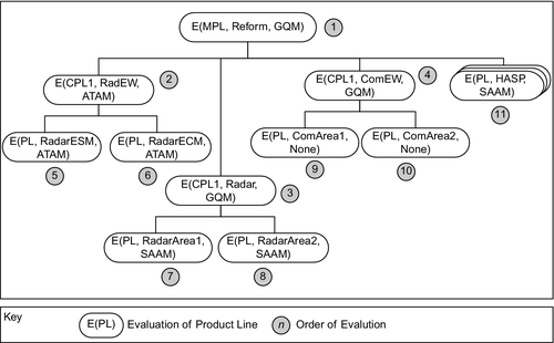
As shown in Figure 10.12, it was decided to do an ATAM for the RadEW and a GQM for Radar and ComEW. For the PLs of RadEW an ATAM was also performed. Each ATAM evaluation took about 1 week. For the PLs of Radar, the team decided to apply SAAM, while the CPLs of ComEW were not evaluated yet. The separate PLs, on the right part of the figure, were either not evaluated or a quick SAAM process was applied (about two days).
10.5.4 Reporting and workshop
The complete design and the corresponding evaluation of the MPL alternatives were reported and written as a technical report (Tekinerdogan et al., 2012). Interactive workshops were held in step 4 (select feasible MPL using GQM) and step 6 (evaluate MPL). For the latter step, we needed more than one workshop meeting to do the evaluation for the separate PLs. The overall evaluation was completed using a final two-day workshop in which the process for selecting the MPL, the modeling of the MPL, and the modeling and evaluation of the required PLs was discussed.
10.6 Related Work
Different industrial cases of MPL engineering have been discussed in the literature. van der Linden and Wijnstra (2001), for example, described the development of multiple product families for the Philips Medical imaging systems (PMS). Typically, several PLs are available because products are developed in different parts of the world and within different product groups. Although the products in the different lines differ a lot, there is also a lot of similar software between them. Because of this, an imaging platform to be used by the whole of PMS was developed. The platform itself was also a PL. Different product groups within Philips are using different variants and platform configurations. Within many of the product groups, software running on top of the imaging platform is built into SPL as well. This induces additional variability requirements to the platform.
In this work, we have focused on the analysis of the composition of MPL within the context of Aselsan REHİS. Each PL is developed by Aselsan REHİS, and there are no external suppliers of PLs. Several authors have indicated the fact that the required PLs could be developed and maintained by external competing suppliers. The availability of alternative suppliers makes it possible to serve a wider group of customers and avoids a dependency on a single supplier. PLs developed by alternative suppliers have been termed as competing PLs. This was not a concern for Aselsan REHİS, so it was not defined in the list of goals derived from the GQM analysis. However, for a different industrial case in which this is important, this could be easily addressed by including a goal on optimizing supplier costs.
Some authors have focused on analyzing the feasibility of product line engineering approach (PLA) for an organization. The Product Line Technical Probe (PLTP) (Clements and Northrop, 2002), as proposed by the Software Engineering Institute (SEI), aims at discovering the ability of an organization to adapt and succeed with the SPL approach. The PLTP is a diagnostic tool that uses the SEI Framework for SPL Practice as a reference model. The Framework for Software Product Line Practice divides the overall SPL process into a set of three essential activities of product development, core asset development, and management. The PLTP uses a set of structured interviews of small peer groups within the organization to identify the framework practices that need to be improved, identify the challenges that need to be addressed, and identify the strengths to build upon.
Fritsch and Hahn (2004) introduce Product Line Potential Analysis (PLPA), which aims to make a quick decision as to whether a PLA is suitable for a given set of products and target market. A PLPA is executed in a half-day workshop that includes structured interviews. The answers to the questions are compared to a set of criteria for the applicability of the PLA and result in “yes,” “no,” or “investigation required.”
Besides analyzing the feasibility of PLA, different product line scoping approaches have been proposed to define a proper PL scope. In this context, PuLSE-Eco (Schmid and Widen, 2000) deals with defining the scope of SPL on business objectives that are identified by PL stakeholders.
Rosenmüller et al. (2008) discuss the problem of dependent PLs, that is, one SPL using functionality provided by another SPL. They describe that only defining constraints between the involved feature models is not sufficient in case multiple differently configured instances are used in a composition of SPLs. Thus the dependencies between the concrete instances have to be considered. Likewise, Rosenmuller et al. present an extension to current SPL modeling based on class diagrams that allows us to describe SPL instances and dependencies among them. An elaboration of this work is defined in Rosenmüller and Siegmund (2010), where the authors show the semi-automatic configuration of MPL based on so-called composition models. To define the MPL metrics, the notion of dependent PLs could be adopted.
Babar et al. (2004) have provided a framework for classifying and comparing software architecture (SA) evaluation methods. This framework has been developed by discovering similarities and differences among existing evaluation methods. We have used this framework to characterize Archample as shown in Table 10.5.
Table 10.5
Characterization of the Approach Using Evaluation Framework as Defined in Babar et al. (2004)
| Method Criterion | Description |
| Method’s activities | Seven activities in four phases + 1 phase with number of activities dependent on selected architecture analysis approach (of step 6 in Figure 10.6) |
| Method’s goals |
– Evaluate whether it is feasible to adopt an MPL architecture – Evaluate ability of MPL architecture to achieve quality attributes – Combine evaluation of MPL architecture with evaluation of single PL architectures |
| Quality attributes addressed | Multiple attributes (GQM and criteria defined in adopted evaluation methods) |
| Architectural description | Using MPL architecture viewpoints and viewpoints in existing architecture frameworks |
| Maturity stage | Inception/development |
| Software architecture definition | MPL architecture, PL architecture |
| Process support | Sufficient process support |
| Applicable project stage | After MPL and PL Architecture; Early analysis |
| Evaluation approaches | Hybrid approach (GQM and existing evaluation methods) |
| Stakeholders involved | All major stakeholders |
| Support for nontechnical issues | Implicit but not explicitly addressed |
| Method’s validation | Validated in one large real industrial project |
| Tool support | Not available |
| Experience repository available | No |
| Resources required | Apart from initial & postpreparation, three days. Four-person evaluation team & stakeholders |

10.7 Conclusion
Recent developments in SPL engineering show the need for MPL in which products are composed from subproducts in separate SPL. Designing and realizing the MPL approach is a challenging and time-consuming task. In this context we have in particular focused on the composition of the MPL PL from separate PLs. It is important to analyze the MPL decomposition early before large organizational resources are committed to the development. Different architecture analysis approaches have been introduced, but none of these focuses on the evaluation of MPL architectures. In this chapter, we have proposed the architecture analysis approach for MPL Engineering (Archample), which has been particularly defined for the analysis of MPL architectures. Archample can be used to support the decision for whether to apply an MPL. Using Archample the possible architecture design alternatives are made explicit and the feasible design alternative is selected and evaluated. An important aspect of an evaluation method is whether it has been validated. Archample was designed within an industrial context and also applied for a large industrial case of Aselsan REHİS. Our experiences show that the application of Archample led to an increased understanding of the MPL architecture and the design decisions. Archample is an evaluation method itself but can also be considered as an approach to integrate evaluation approaches within an MPL context. Our future work will be focused on developing tool support to represent the architectural views and support the steps of Archample.