A Rule-Based Approach to Architecture Conformance Checking as a Quality Management Measure
Sebastian Herold*; Andreas Rausch Clausthal University of Technology, Clausthal-Zellerfeld, Germany
Abstract
The process of divergence between intended software architecture and its actual implementation, often called architecture erosion or architectural drifts, has in general negative effects on the overall quality of the system. It is hence very important to be able to check whether the realization of a system conforms to its intended architecture.
Consistency between models and conformance are important issues in model-based software development. Conformance between models can be guaranteed partially “by construction” through conformance preserving (semi-)automatic model transformations. Nevertheless, due to manual modification of models and the refinement and abstraction steps from high-level models to more detailed models, complete inter-model consistency cannot be guaranteed a priori in general but must be checked regularly.
In this work, we address the checking of architectural conformance in a model-based development setting. The broad range of sources for architectural rules, that is, constraints restricting the way an architecture can be implemented and the large number of different artifacts influenced by them, requires very flexible tool support that is challenging to realize. We describe an approach to flexible architecture conformance checking based on a formalization of architectural rules as logical formulas. The approach is implemented prototypically and is applied in small application scenario.
Introduction
The intended software architecture of a system captures the most far-reaching design decisions that are made during the development of a software system (Bass et al., 2003). It influences and determines very strongly the quality attributes of a software system. However, especially in complex and long-living software systems, it is likely that the realization of a system diverges from the intended software architecture. This effect is also known as architectural erosion or architectural drift (Perry and Wolf, 1992) and is hard to detect manually due to the size and complexity of software systems. These effects threaten quality properties of the system such as maintainability, adaptability, or reusability (Van Gurp and Bosch, 2002). Uncontrolled architecture erosion can lead to irreparable software systems that need to be replaced (Sarkar et al., 2009).
Software architecture erosion can be seen as a consistency problem between artifacts of software development processes. Consistency between artifacts has been intensively investigated in model-driven software development (MDSD) research, especially in the subfields of model transformations and inter-model consistency (Lucas et al., 2009). Nevertheless, Biehl and Löwe (2009) were among the first who showed that architecture erosion also might occur in MDSD approaches.
Model transformations describe the relationship between models, more specially the mapping of information from one model to another. Thus models are converted from one particular perspective to another and from one level of abstraction to another—usually from more to less abstract—by adding more detail supplied by the transformation rules.
It could be assumed that model transformations ensure that high-level artifacts, for example, UML models, are consistently transformed into low-level artifacts, for example, source code. However, the transformations in general do not create the entire set of low-level artifacts. Instead, they create skeletons that need to be manually extended and completed. Due to this semi-automation, projects developed with MDSD are also prone to the problem of drifts between the various models on different levels of abstraction and views with different perspectives. Such inter-model drifts can be introduced for various reasons, such as manual additions or incomplete or incorrect transformations (Biehl and Löwe, 2009).
Moreover, general purpose consistency checking approaches common in MDSD are difficult to use for erosion detecting in typical development scenarios. In these approaches, the specification of consistency constraints depends on the syntax of the participating models, and hence haveto be repeatedly defined for each kind of model in which architectural erosion might appear. This redundancy limits the usability of these approaches for detecting erosion.
The focus and contribution of this chapter is in the area of architectural design within MDSD approaches. We will present an approach that allows integrating effective architecture erosion detection into MDSD more easily than existing solutions. Different models are represented as instances of a common ontology and architectural consistency constraints, which are called architectural rules in the following, are expressed as logical formulas over these structures. These are rules defined by architectural aspects like patterns that restrain the detailed design or the implementation of the system. The approach enables us to support a broad variety of architectural aspects in architectural conformance checking due to the formalization by first-order logics and allows us to integrate new meta-models easily because architectural rules are largely meta-model-independent.
The remainder of this chapter is structured as follows. Section 7.1 describes the necessity and the challenges of architectural conformance checking in more detail. Section 7.2 will give an overview of related work and approaches. The proposed approach is described in Section 7.3. In Section 7.4, the application of the approach in a detailed scenario as well as further case studies is described. Section 7.5 will address the contribution of the approach and its limitations.
7.1 Challenges in Architectural Conformance Checking
Software design activities can be separated into three groups (see Figure 7.1): software architecture, detailed design, and implementation (Clements et al., 2010). Artifacts created by those activities provide different views on the inner structures of a system with different levels of abstraction, adding more and more details starting at the most abstract view of the software architecture. As stated in the most common definitions of the term, the software architecture contains components and their externally visible interfaces (Bass et al., 2003; Hofmeister and Nord, 1999). These structures are refined during the detailed design and complemented by the inner structures of the components. The implementation, finally, provides the complete and executable system.

Current large-scale systems have up to several hundred million lines of code; large object-oriented systems are made of several thousand classes. Ensuring architectural conformance manually for systems of that size and complexity is impossible and, even for smaller systems, time-consuming and error-prone. It is obvious for such settings that conformance checking cannot be performed manually. The software architect clearly requires tool support.
Figure 7.1 illustrates typical software development phases and the relationships between them. An architectural description, a model in MDSD, defines architectural rules that restrict the content of models worked with during detailed design and implementation. This is complex with regard to two aspects:
1. The set of artifact types—in MDSD the set of meta-models—used to describe the system that can be affected by architectural rules is heterogeneous and differs from project to project.
2. There is a large variety of architectural rules. Different architectural concepts, like patterns, reference architectures, or design principles can define rules that need to be checked in design and implementation.
Tool support that does not support these two complexity issues does not allow flexible and exhaustive architectural conformance checking. As a result, a probably expensive and hard-to-handle tool chain is needed for architectural conformance checking.
The inherent complexity of architecture conformance checking is tightened by the observation that the separation between the steps in the design process—architectural design, detailed design, and implementation—is most often unclear in both practice and research.1
Informal attempts to define a clear separation of concerns between architectural design and detailed design are made in software architecture literature with moderate clarifying contributions. Many definitions are along the lines of the one in Kazman (1999), which states that “Architecture […] is design at a higher level of abstraction,” without explaining whether there is a “threshold abstraction level” that distinguishes the two steps—and, if there is one, how it is defined. In Clements et al. (2010), the definition of software architecture makes a distinction: If software architecture is about the externally visible properties of components, detailed design is about the internal hidden properties. This definition does not help the effort to select an appropriate granularity for software architecture. Essentially, it says architectural things are those that the software architect defines to be architectural; everything else is subject to detailed design.
A clear distinction, however, is important for architectural conformance checking in order to clearly characterize architectural rules and to decide on the required expressive power to describe them. Theoretical work on the distinctions of architecture, design, and implementation, as described in Eden et al. (2006), exists but is not widely applied in practice.
In the following, we will see that the state of the art in architectural conformance checking does not provide solutions for MDSD approaches that provide the required flexibility.
7.2 Related Work
As outlined in the section “Introduction,” general transformation and conformance checking techniques from MDSD, like xlinkit, ECL/EVL, or similar approaches (Lucas et al., 2009; Nentwich et al., 2002; Rose et al., 2008) could be used to check architecture conformance, but they do not provide the required flexibility. Let us assume that a software architect wants to enforce the hierarchical layering of a system defined in an architectural model. He could define transformation rules that create for each layer a package in a UML model (for the detailed design of a system) with attached constraints allowing only dependencies in a way that the layering is followed.
The constraints, as part of the target side of a transformation rule, naturally refer to elements of the target meta-model and are hence meta-model-specific. In realistic scenarios with different meta-models in use for one software development project, a single architectural rule has thus to be manifested in many different sets of transformation rules. The constraint would have to be defined repeatedly for different meta-models, creating overhead in the process of maintaining the set of architectural rules.
On the other hand, there specialized approaches for architectural conformance checking. Passos et al. (2010) distinguish Dependency Structure Matrices (DSM), Code Query Languages (CQLs), and Reflexion Models as different techniques. DSM are a technique to represent and analyze complex systems in general (Steward, 1981). Regarding architectural conformance checking, approaches based on DSM represent the simplest form of checking approaches. The main idea is to represent a system as a square matrix. The value eij denotes a dependency between the element i and the element j of the system, for example, modules and components.
Lattix LDM (Sangal et al., 2005) is a tool to create, analyze, and control a software architecture in terms of allowed dependencies based on DSM. In Hinsman et al. (2009), a case study is described in which Lattix LDM is successfully applied to manage the architecture of a real-life system and to execute refactorings.
That case study also shows what DSM focuses on and what kind of architectural rules are supported: Basically only dependency rules can be explicitly formulated. Hence, more complex architectural rules—for example, for different patterns—cannot be captured. Moreover, the dependency rules inside the LDM tool have to be kept manually consistent with an existing architectural model, causing additional maintenance efforts.
Source CQLs allow one to formulate queries upon a base of source code and retrieve single elements or more complex substructures from it. Such query languages can also be used to define queries retrieving elements that adhere to or violate architectural rules. In a similar way, constraint languages check constraints on a pool of data and can be used for architecture conformance checking. Examples of languages that can be used for this purpose are, for example, the CQL, .QL (de Moor et al., 2007), SCL (Hou and Hoover, 2006), or LogEn (Eichberg et al., 2008). Approaches based on such languages have in common that they often allow conformance checking for a small set of programming languages only and do not provide a high-level architecture model. However, given that these languages are mostly based on a relational calculus or first-order logics, they allow expressive architectural rules.
Reflexion modeling was introduced in Murphy et al. (2001) as a technique supporting program and system comprehension. Here the assumed or intended software architecture of a system is described by a high-level model, containing elements and dependencies as they are expected to be. After that, a dependency graph is automatically extracted from the existing system artifacts, source code in most cases. The graph created is also called the source model. In the following step, a mapping between elements of the high-level model and the source model is created manually, capturing the “common” elements of the intended high-level architecture and the actual structure of the system. As a next step, the actual comparison of both is presented in a reflexion model.
Reflexion modeling is implemented in many approaches and tools. The Fraunhofer Software Architecture Visualization and Evaluation tool follows the reflexion modeling approach (Knodel et al., 2006; Lindvall and Muthig, 2008) as does the tool ConQAT (Deissenboeck et al., 2010) and the Bauhaus tool suite (Raza et al., 2006), to name a few.
All reflexion-based approaches have in common that a mapping between architecture and source code elements (in fact, they all check source code but not detailed design artifacts) is required to keep track of how architectural elements are realized in code. In model-driven development, this information could be partially retrieved from persisted transformation information, such that manual creation of mappings could be easier or completely omitted. This redundancy of information is therefore a minor but not unsolvable drawback in the context of MDSD. The particular approaches illustrate that flexibility of conformance checking with regard to different artifact types is possible using reflexion modeling. However, compared with query language-based approaches or constraint-based approaches, their expressiveness to architectural rules is limited because they do not allow the specification of arbitrary constraints about the structures they define but focus on dependencies.
7.3 A Formal Framework for Architectural Conformance Checking
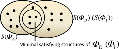
The proposed approach consists of a conceptual framework that is based upon the formalization of models and other system descriptions as first-order logic formulas describing which properties a conforming system must have. Figure 7.2 illustrates the approach graphically.
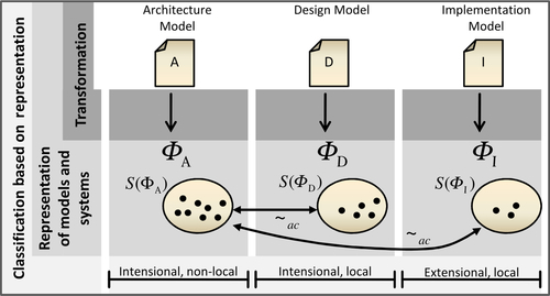
A model M (such as an architecture A, a detailed design D, or an implementation I) is transformed into a set of first-order logic statements ϕM that represents M formally. The interpretations satisfying ϕM, depicted as S(ϕM), represent those systems that conform to the model M. Formally, the elements of S(ϕM) are relational structures, consisting of a universe of entities and relations between them. Based on the sets S(ϕM), we can apply the two formal classification criteria by Eden et al. (2006), that is, intensionality/extensionality and locality/non-locality. We are thus able to formally distinguish models of those three development steps and to define precisely what architectural rules are. As a consequence, the term architectural conformance can be interpreted as relation ~ ac between the sets of satisfying systems for an architectural model and one of its refining models.
In the following, we will first describe the formalization of component-based systems as logical structures conforming to a signature τCBSD of relation symbols that forms, together with an axiomatic system ΦCBSD, an ontology for component-based systems.2 After that, the representation of models and their transformation into logical formulas will be described. The term architectural conformance will be defined. Finally, we will describe the implementation of the approach by a prototype based on a logical knowledge representation system.
7.3.1 Formal representation of component-based systems
As already mentioned, component-based systems are formalized by a kind of ontology defined by a set of relation symbols, the signature τCBSD, and an axiomatic system ϕCBSD. τCBSD defines which relation symbols can be used as predicates to form logical statements about component-based systems; ϕCBSD defines general constraints that pertain in such systems. A dedicated component-based system is therefore represented by a set of entities representing elements of the system and a mapping of the available relation symbols of τCBSD onto relations over the set of entities. In the following, we speak of τCBSD-structures as relational structures using relation symbols from τCBSD, and of systems if a structure additionally conforms to the axioms from ϕCBSD.
The upper part of Figure 7.3 shows a relational structure modeling a very simple component-based system. The relation Components, for example, is the corresponding relation for the relation symbol Component in the system s and reflects the set of components in the system.3
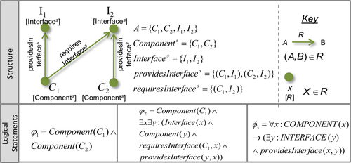
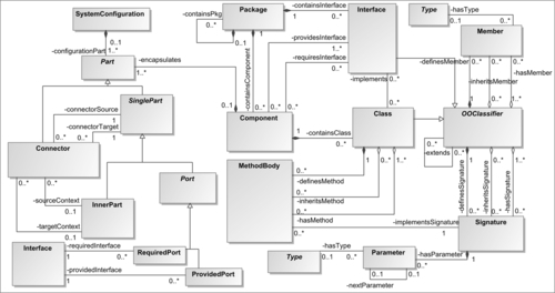
Figure 7.4 illustrates a cutout of τCBSD graphically as a UML class diagram. Classes can be interpreted as unary relation symbols of τCBSD, whereas associations are interpreted as having a binary relationship. Furthermore, the diagram also visualizes “typing” axioms of ϕCBSD by specialization and the types at association ends. For example, the specialization between Class and OOClassifier represents the axiom
![]()
and the association providesInterface implies the axiom
![]()
The multiplicities of associations can also be translated into axioms for the minimal or maximal number of tuples in a relation for a fixed tuple component.
The depicted cutout of τCBSD models the organization of components and interfaces into packages, as well as the internal structures. Component and Interface stand for components and interfaces, respectively, and are contained in packages (Package). Interfaces contain a set of signatures (Signature), indicating the methods that an implementation must provide, and members (Member), or attributes. As these features are also provided by classes (Class), they are defined in a common superclass OOClassifier. The different relations modeled by hasX, definesX, and inheritsX reflect the different possibilities for relating signatures or members to classifiers by inheritance or defining; the set of all available signatures of one classifier, for example, is addressed by hasSignature, which is the union of definesSignature and inheritsSignature. Interfaces are provided and required by components, as modeled by providesInterface and requiresInterface.
Classes are interpreted as component-local classifiers that implement those interfaces that the component provides. The internal structure of components is reflected in parts (Part, related by encapsulates) that can be typed by components or classes (because Component and Class are specializations of Type). Special parts are Ports. Provided ports (ProvidedPort) are parts that are accessible from the environment of a component; required ports can be understood as place holders usable in the specification of a component, indicating a reference to a port that has to be provided by a different component at runtime. In contrast to ports, inner parts (InnerPart) are not accessible from outside a component. Ports are connected by connectors (Connector), which represent links between objects at runtime. Connectors are directed from connectorSource to connectorTarget, which are also parts. If the connected parts are ports, for example, the location of the parts where the ports are located must be idenfitified prior to connecting two component-typed inner parts of a component. This is modeled by sourceContext and targetContext. The specification of a whole system is done by SystemConfigurations that are structured the same way as components by parts (see relation configurationParts), only differing in the fact that all parts must be typed by components, not classes.
Constraints like this are also part of ΦCBSD. The example of system configuration parts that need to be typed by components can be expressed by the following axiom:
![]()
τCBSD and ΦCBSD furthermore define the behavior specification of component-based systems contained in MethodBody. The relevant relation symbols formalize control flow graphs (Allen, 1970) and different types of statement nodes such as instance creation and destruction, asynchronous and synchronous communication, and the assignment of references. For the sake of brevity, we omit the details and refer the reader to Herold (2011).
7.3.2 Formal representation of models
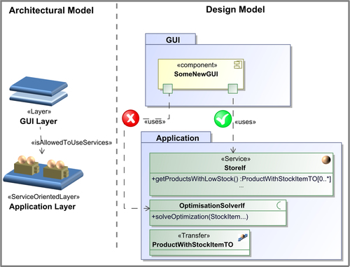
As mentioned above, models are represented as first-order logic τCBSD-statements; these are statements that use relation symbols from τCBSD among others. This means that additional relation symbols can be defined and used if necessary. As an example of a statement representing a model, consider the UML design model cutout of Common Component Modeling Example (CoCoME) depicted in Figure 7.8. It shows that the component StoreGUI requires the interface StoreIF. This informal statement can be translated to a first-order logic statement over τCBSD-structures:
![]()
whereas ex is the entity representing the element x in the model. In the following, we will denote with ϕM the set of τCBSD-statements for a model M. Logical statements are evaluated over relational structures as introduced, and we will denote by S(ϕM) the set of systems that fulfill the set of formulas ϕM.
7.3.2.1 Classification of models
According to the classification scheme by Eden et al. (2006), we can distinguish architectural models, design models, and implementations by their sets of statements and properties of their sets of satisfying structures. A statement is called extensional if and only if each of the structures satisfying the statement is closed when addition and removal of elements. This means that
• adding entities or tuples containing new entities to the structure and
• removing entities or tuples that are not directly referenced in the statement
lead to structures satisfying the statement as well.
Statements that are not extensional are called intensional. Consider the statement examples in Figure 7.3. The depicted structure satisfies them all. Only the leftmost example is extensional, and neither adding entities nor removing other entities than C1 or C2 from the structure will change the evaluation of φ1. φ2 would evaluate to false if all interfaces were removed; φ3 would evaluate to false if we added a component providing no interface.
Moreover, we call statements that are at least closed under addition local; such statements claim properties of systems that, once established, cannot be lost. Statements that are not local are called non-local; a system that satisfies such a statement can in general be extended in a way that the resulting system does not satisfy the statement any more. In Figure 7.3, only φ3 is non-local.
Eden argues that statements being both intensional and non-local are those defined by architectures; such statements define constraints that are “system-global” constraints in the sense that their impact cannot be locally isolated. For example, the layering of a system is non-local; although a system may be correctly layered at some point, a component could be integrated and related to other components such that dependencies would form a cycle and the layering would be violated. We call constraints like that architectural rules. In contrast, consider two classes/components realizing an observer-observable relationship. The constraint about what makes them a “valid” observer or observable is local to the two components; it describes the interaction between these two alone, which stays the same if further components are added to the system in any case (see Eden et al., 2006 for details).
Hence, we define two partitions ΦM ![]() ϕMext
ϕMext ![]() ϕMint for the set of statements for a model M, which contain the extensional and intensional statements of M, respectively. Furthermore, we call a model M(a) architectural if its set of intensional statements contains non-local statements (architectural rules), (b) a design model if its set of intensional statement contains only local statements, and (c) an implementation if its set of intensional statements is empty.
ϕMint for the set of statements for a model M, which contain the extensional and intensional statements of M, respectively. Furthermore, we call a model M(a) architectural if its set of intensional statements contains non-local statements (architectural rules), (b) a design model if its set of intensional statement contains only local statements, and (c) an implementation if its set of intensional statements is empty.
7.3.2.2 Transformation of models
The transformation of models into τCBSD expressions can be specified by transformation definition depending on a model's meta-model. Formally, we can express the transformation definition TL for a given meta-model L as
![]()
whereas ClassL denotes the set of meta-classes defined in L and ![]() denotes the set of extensional first-order logic expressions containing navigable expressions over τL ⊆ τCBSD and
denotes the set of extensional first-order logic expressions containing navigable expressions over τL ⊆ τCBSD and ![]() the set of intensional statements. Navigable expressions mean that the structure of the meta-model can be exploited to refer to objects in the model that has to be transformed. For example,
the set of intensional statements. Navigable expressions mean that the structure of the meta-model can be exploited to refer to objects in the model that has to be transformed. For example,

![]()
that for each component in a UML model according tuples of providesInterface and requiresInterface are generated for each interface that is referred to in the model by this.provides (whereas “this” refers to the current component, see also OMG (Object Management Group), 2010).
7.3.3 Conformance of models
It is obvious that conformance between architecture and design cannot be defined as classical refinement relation stating that every satisfying system of the design model must also satisfy the architectural model. The statements for the design model are local, hence every extension of a satisfying system s satisfies the design model, too. If s also satisfies the architectural model, this does not necessarily have to be the case for every extension. Consider an architectural design model describing components A, B, and C that are correctly dependent on each other with regard to the layer modeled by the architecture. A component D can be added to the system,4 destroying the correct layering.
Instead of claiming that every satisfying system of the design is also a system for the architecture, the constraint for conformance is weakened to a certain subset of satisfying systems: Only the minimal systems of the design (or the implementation) have to also satisfy the statements of the architecture (see Figure 7.5). A system is called minimal for a set of logical statements if it satisfies the set of statements, and no element or relationship could be removed from the system without losing this property.
Unfortunately, the set of minimal systems can be infinitely large. Consider the extensional statement Component(StoreGUI). There is a single minimal satisfying structure, containing only one entity in the set of components. But unfortunately, the axioms of ΦCBSD mention that components must be nested in packages, hence every system consisting of the single component StoreGUI in a package is a minimal system—infinitely many.
Therefore we make three restricting assumptions that have to be valid for models that can be checked for conformance. If all of these are valid for a model M, there is a unique minimal system for M, as follows:
1. Extensional statements of M are conjunctions of facts. This means that they are conjunctions of terms of the form Pred(e1,…,en) where Pred is an n-ary predicate and ei refers to entities.
2. A structure that satisfies ϕMext also satisfies ϕMint. This means that a model satisfies its own constraints.
3. Every minimal structure satisfies the axioms of ΦCBSD, that is, minimal structures are also minimal systems.
There is at most one minimal structure for statements described in (1). Assumption (2) ensures that if this unique minimal model for the extensional part of a model exists, it is also a satisfying structure for the whole model. Assumption (3) finally ensures that the minimal structure is a minimal system.
The prototype presented in the following section implements conformance checking following this definition and these assumptions. Note that a minimal model for the extensional statement can be generated and that the assumptions can be checked by model checking.
7.3.4 Prototypical implementation
To evaluate the approach to architectural conformance checking, a prototypical tool called ArCh has been implemented. It is based on a realization using logic knowledge representation systems like Prolog or Powerloom (Information Sciences Institute, 2006). The overall structure and functionality of ArCh is depicted in Figure 7.6. The tool concept is integrated into Eclipse.5
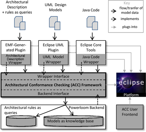
The main component of ArCh is the Architecture Conformance Checking Framework. It realizes the functionality of conformance checking based upon the definition explained in Section 7.3.3. It also defines an internal representation of relational structures as used in the proposed approach. This is used by the wrapper interface to define a standardized interface to structures conforming to τCBSD. Another interface, the backend interface, encapsulates the specific knowledge representation system and keeps the implementation interchangeable.
Different wrappers encapsulate instances of different meta-models (or programming languages) and provide a τCBSD-view onto models (or source code) that need to be checked. Currently, UML and Java are supported as well as simple examples of architecture description languages. Note that in the scenario described in this chapter, no separate meta-model for an architectural model of CoCoME has been defined; instead, two instances of a UML wrapper have been used, one responsible for the architectural model written in UML.6 For arbitrary meta-models following the MOF (OMG (Object Management Group), 2006), plugins generated by EMF can be used to access models (Steinberg et al., 2009).
At the moment, the transformation of MOF-conforming meta-models is realized programmatically by navigating the model's structure through the API provided by EMF. One of the next development steps will be to replace the programmatic transformation with model transformations that create the internally used data model from EMF models. The transformation for Java has been realized as a programmatic transformation using the Eclipse development tools that provide an API to the abstract syntax tree of Java source code.
The transformation definitions, that is, the queries representing the logical sentences for the architectural rules that a meta-model element implies, are stored separately and serve as input for the corresponding wrapper. The framework also supports loading queries from libraries in which common queries can be stored for reuse.
The framework forwards the relational structures representing the models as merged structure to the connected backend that represents it specifically for the implementation as logical knowledge base. As of yet, an implementation for third-party system Powerloom has been realized. Architectural rules are represented as logical queries and executed by the knowledge representation system in the process of conformance checking. The source for rule definitions can be any source for strings. In the case of the wrapper for layered architectures, a simple text file is attached to wrapper instances during their initialization. It contains a comma-separated list of entries of the form
< meta model element >,<rule-def >,<rule-desc >
< meta model element > refers to the element of the meta-model for which the rule is generated, < rule-def > contains the rule definition, and < rule-desc > is an informal description of the rule definition. The actual rule definition is PowerLoom query code. For example, the entry
“Layer”,
“(illegalLayerDependencies ?this ?toLayer ?srcElem ?trgElem)”,
“Actual layer dependencies are not compliant with intended ones!”
reflects basically the top-level statement of the architectural rule described in Section 7.4.1.2. Figure 7.7 shows the result dialog of ArCh checking a modified CoCoME system in which a logging component was added to the application layer. As the logging component is used in the entire inventory subsystem, the dependencies cause architectural violations.
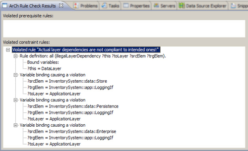
The prototype can either be used interactively or in a batch-like mode as part of an automated process. In the first mode (also shown by the screenshot in Figure 7.7), the user can configure the set of related artifacts, for example, the architecture of the system and the folder of Java source code, and check this set for architectural conformance. In batch mode, ArCh can be integrated into an automatic build process, such as a nightly build, and generate reports about architectural conformance of the system. This allows continuous and effective checking of architectural conformance.
7.4 Application of the Proposed Approach
In this section, we describe the application of the proposed approach in different case studies. The first case study on the CoCoME will be covered in detail and the formalization of architectural rules will be explained. The further case studies will be summarized briefly and informally.
7.4.1 The common component modeling example
The CoCoME is a system that has been developed for a comparative study of component-based development approaches (Rausch et al., 2008). The system, also called Trading System for short, supports basic business processes in retail stores like supermarkets. The Trading System covers two functional areas: It supports the process of selling goods at cash desks, and it helps with the management of inventory, including ordering new goods, determining low stocks, and so forth.
7.4.1.1 Architectural aspects of CoCoME
The Inventory subsystem of CoCoME is a kind of typical information system. It is structured according to the common Three-Layer-Architecture (Fowler, 2002) that defines a data layer, an application layer, and the graphical user interface (GUI) layer from bottom to top. While the GUI layer is responsible for user interaction, that is, presenting data and receiving user input, the application layer realizes business logic. The data layer is responsible for creating, reading, updating, and deleting data from persistent storages like databases. The layering in the case of CoCoME is strict, which means that the GUI layer may access the application layer but not the persistence layer directly.
As already mentioned, the layering of a system groups the components of the system hierarchically. In general, however, the allowed usage relations are specified in addition explicitly because normally a general right for upper layers to use every layer below is not desirable, for example, in strict layerings. Hence, the following informal constraints have to hold for layers in general:
• A layer L may only use functionality of L itself or
• L may use functionality of layer M (L ≠ M) if L is at a higher level than M and L is explicitly modeled to be allowed to use M.
Hence, a layer in general imposes the architectural rule that the content of a layer may depend only on content of the layer itself, or content in layers that the containing layer is explicitly allowed to depend on. A dependency in component-based systems exists in the following cases:
• Usage between components and interfaces, that is, components providing or requiring an interface, makes a component depend on the interface signature.
• Specialization between interfaces leads to a usage relation between the specializing and the generalized interface.
• Usage of interfaces. An interface using another interface as method argument type or return type, or as type of a reference.
• Method calls. The implementation of a component calls a method at another component (e.g., connected via a connector to a required port) synchronously. Because of the non-blocking behavior of asynchronous communication, the calling component does not depend on the “correct” behavior of the method invoked.
Figure 7.8 depicts a cutout of the CoCoME architecture and design models and shows a violation of this architectural aspect.

Another architectural aspect affects the application layer interface that is accessed via a network in the CoCoME system. One way of accessing a remote interface is via remote method invocation using middleware that includes marshaling and unmarshaling of calls. Due to these mechanisms, each call of a remote object's method, like reading object attribute values or navigating references to associated objects, causes overhead for this kind of communication (Fowler, 2002).
A common solution to this problem is the use of data transfer objects (Fowler, 2002). Instead of passing references to the web of persisted objects to the GUI layer, the required fragment of this web is copied into transfer objects. These copies are transferred to the GUI layer via the network; the GUI, running at a remote client computer, gets its own local and hence efficiently accessible copy of persisted data. We therefore also say that a component handling the passing of data the manner described provides an interface with copy semantics (in contrast to reference semantics). This concept is also an important part of service-oriented architectures (Krafzig et al., 2004).
The informal architectural rule defined by this concept is:
• The client of a service-oriented layer may connect only to interfaces that are declared service interfaces.
• A service interface is an interface providing service methods only. Those methods use only transfer object classes or primitive types as parameter types or result types. Each call of a service method returns a new copy of data, that is, a new instance of the transfer object class. This ensures that two different clients do not share a single instance as returned value.
• A transfer object class contains only attributes of primitive types or other transfer objects classes; a transfer object never refers to an object that is not a transfer object. Especially objects from the domain model are not allowed.
Figure 7.9 shows a fictitious violation of this concept in the CoCoME system.
As mentioned above, the components of the Cash Desk System interact by causing and reacting to events. The event of scanning a product bar code (which is raised by the bar code scanner) causes reactions of other components: The running total is updated and visualized on the cash box display, and the receipt printer prints another entry of the sale. Such a system is also said to have an event-driven architecture (Yochem et al., 2009). A common way of realizing an event-driven architecture is to use the Event Channel pattern (Buschmann et al., 1996), a special variant of the Publisher-Subscriber pattern (Gamma et al., 1995).
In CoCoME, there are actually two kinds of event channels. Each single cash desk has a separate channel connecting the software controllers for the single devices; the channel is for the communication among them and the communication with the cash desk application. For the whole cash desk line, there exists an event channel with which the single cash desk applications register as publishers; the already mentioned application layer component StoreApp of the inventory system registers as subscriber. The cash desks publish SaleRegisteredEvents onto this channel, indicating that a sale process is finished. As a reaction to this event, the inventory system updates the amounts of goods in the inventory. Figure 7.10 depicts this structure and shows also a violation of the following rules that apply:

• There are two kinds of components in the considered subsystem: event channels and participants. The latter are publishers or subscribers (or both).
• Components interact by raising events modeled as a specific kind of type and reacting to them.
• Participants connected to the same event channel are not allowed to communicate directly with each other.
• Participants commit events to the event channel, which ensures that these events are forwarded to the other participants at some point. This happens decoupled from the original commit call to provide an asynchronous communication between participants.
7.4.1.2 The architectural rules of CoCoME
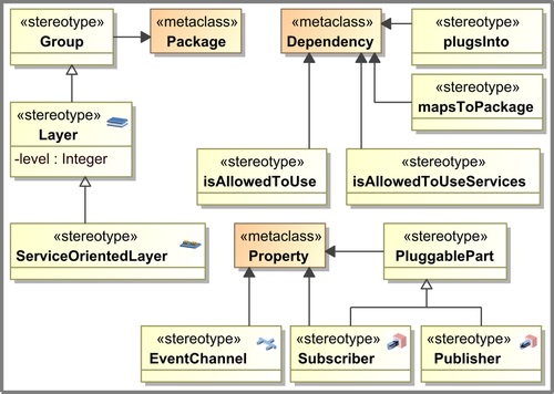
The proposed architecture conformance checking approach has been applied to check a design model of CoCoME described in Rausch et al. (2008) and refined in Herold (2011). The architecture of CoCoME was modeled using UML with architectural profiles that captured the relevant concepts. Figure 7.11 depicts the stereotypes used for CoCoME. The stereotype Group extends packages and reflects “virtual” groups of elements as outlined in Zdun and Avgeriou (2008). The Layer stereotype specializes Group and adds a level attribute reflecting the position of the stereotyped package in the layer hierarchy. A further specialization of Layer is ServiceOrientedLayer marking layers with copy semantics interface. The allowed usage relationships can be modeled by dependencies stereotyped with isAllowedToUse. The stereotype mapsToPackage extends the meta-class Dependency of the UML meta-model. It indicates which packages' contents are part of the “virtual group”; in our example, this relationship indicates by which packages a layer is manifested. The stereotypes EventChannel, Subscriber, and Publisher are used to model the event-based architecture; they extend Property because they label parts of subsystems modeling the single component instances of a subsystem playing one or more of the three roles in event-based architectures.
For the sake of brevity, we will only consider the architectural layer aspect and will give a detailed description of the transformation for this aspect only. The stereotype Layer is transformed as follows:
![]()
whereas the second statement constitutes an architectural rule, it basically states that there are no dependencies allowed that are not covered by parallel isAllowedToUse dependencies in the architectural model (see Figure 7.8), that is, there exist dependencies that do not conform to an existing isAllowedToUse tuple:

A group dependency between g and g′ exists if g contains an element that depends on an element contained in g′.
![]()
Whereas inGroup reflects the containment relationship. An element is contained in a group if it is directly contained in a package that the group maps to, or one of the package's subpackages. This also means that elements of groups are either components or interfaces, the only elements that are contained in packages by the definitions of τCBSD:

dependsOn(e,e′) is a container for the different possibilities of how single elements in a component-based system can depend on each other. It is defined as
![]()
The complete refinement of this sentence and the overall rule for layers can be found in Herold (2011). For example, to express that an interface e depends on another interface f if it uses f as type of a member, we can define
![]()
7.4.1.3 Results of checking the architectural rules of CoCoME
The architectural layering of CoCoME implies the following architectural rules that need to be checked:
We will not go into the details of the evaluation of these rules. But informally, every layer is mapped onto one package in a design model or code. GUI layer components, that is, components contained in the GUI package, use only other GUI components or transfer object interfaces and services that are both defined at the application layer. No dependencies can be detected between elements of a layer and any layer above, and therefore no illegal dependencies can be detected. Moreover, event channels are properly used and are the only communication path in the cash desk subsystem.
However, an architectural violation has been detected for the application layer interface. This is the case because of the component StoreApp depicted in Figure 7.12, which is instantiated in the application layer. A component instantiated in the GUI layer connects to this component via its port storeIf. However, this port also provides the interface connecting the component to an event channel. Hence, it does not hold that the all components in the application layer are accessible by services only. In fact, the result that the approach notices a violation of the architecture makes sense. The accessed object, the port storeIf, appears as a service implementation by the fact that only the interface StoreIf is visible to the GUI; however, the non-service methods of the object could be retrieved, for example, by reflection.

7.4.2 Further case studies
7.4.2.1 Checking layers
In another case study, we investigated a medium-sized information system of about 1600 classes and 130,000 lines of third-party code and a given logical layer architecture that was determined together with the provider of the system. In Deiters et al. (2009), we applied a preliminary version of this approach not using a common ontology. Instead, it could only represent UML models formally and was hence only able to check a reverse-engineered UML model of the Java code. Moreover, there was no explicit architectural model, but architectural facts had to be entered manually.
After this first experiment, we applied the proposed approach and the rules for layers as developed in the CoCoME application scenario. With our prototype and the existing UML and Java wrappers, we were able to detect the same points of erosion/architectural rule violations independently in the UML model of the system as well as in the Java implementation. Several hundred violations were detected that could be distinguished into five groups of different pairs of participating layers. Most of these violations could be reduced to conceptual problems like conceptually wrong placement of classes with a dedicated functionality. This case study has shown that the implementation of the approach was able to handle medium-sized systems with an architecture at a level of detail common in industrial practice.
Furthermore, we analyzed the layered architecture of the open source tool JEdit. In Patel et al. (2006), a reverse engineering approach detected 14 layers in the JEdit system that we used as input as intended architecture for ArCh. Checking the implementation of JEdit—consisting of about 300 KLOC of Java Code—against this architecture with ArCh revealed about 350 violations. Structure 101, for example, detects a similar but slightly higher number of violations due to technical reasons in the way ArCh transforms Java source code into logical facts; it does not transform all available constructs of the Java language correctly yet.
However, the advantage of ArCh is its flexibility, which enables it to detect violations other than layer violations due to its expressiveness. This, of course, comes with a higher complexity of the checking process, which, however, is not a problem so far. After transforming the source code of JEdit into a factbase, which takes about one minute, the current implementation of ArCh is able to check the layering of the system in less than 2 s.
7.4.2.2 Checking domain-specific reference architectures
In this case study, we enabled architecture erosion detection for a domain-specific reference architecture at the German Federal Office of Administration (BVA). The BVA supports German ministries and their departments by providing administrative tasks centrally, such as payments of salaries, time and attendance recording, and many more. It recently introduced a reference architecture called Register Factory7 as a reference architecture for IT systems carrying out tasks around all different kinds of registering in the public administration.
The reference architecture provides guidelines for technical platforms as well as the logical structure of application systems. Given a detailed but informal description of the main aspects of the Register Factory, we developed a domain-specific modeling language such that instances of the reference architecture—hence, architectures for dedicated application systems—could be modeled. We analyzed six different architectural aspects including layers but also patterns regarding the prescribed component structure and formalized them as architectural rules.
The conformance checks revealed about 10 violations of the reference architecture in a register application consisting of about 900 classes and 60,000 lines of Java code. Details about the case study can be found in Herold et al. (2013).
7.4.3 Results
The case studies have shown us encouraging results. The approach provided the required flexibility to express very different aspects of software architecture from general patterns such as layering to domain-specific concepts of a reference architecture. We were able to check architectural for different architecture meta-models as well as different “implementations” of the architecture in forms of UML models or Java source code.
The detected architecture violations were in all cases relevant matches that revealed more or less severe cases of eroded architectures. In a single case we found false positives that in all cases were results of incomplete or wrong formalizations of informally described architecture concepts that could be corrected together with the responsible software architects of the software system.
The applied prototype showed satisfying performance in the case studies. It took about one minute to check the mentioned Register Factory application or to check large layered systems. This performance is sufficient for a batch-like checking process, for example, as an integrated part of a nightly build of a software system. If a more interactive mode of operation is required, for example, for instant feedback to the programmer from getting shown compiler errors in modern IDEs, the performance must be improved.
7.5 Conclusion
As outlined in Section 7.1, adequate tool support for architectural conformance checking requires flexibility with respect to the heterogeneous set of architectural concepts used in a software architecture as well as with respect to the large number of different artifact types, or meta-models, that need to be checked. In MDSD approaches, furthermore, an approach to architectural conformance checking should integrate smoothly with existing techniques and models used to describe software systems.
7.5.1 Contribution and limitations
The ontology defined by τCBSD and ΦCBSD describes component-based systems in great detail, such that architectural rules have great expressiveness. It enables software architectures to describe rules restricting type structures like inheritance; the inner structure of types such as components, interfaces, and classes; the configuration of component-based systems; and the control flow graphs of methods as specifications of component behavior. The framework, however, allows this ontology to be extended by relation symbols to introduce new architectural concepts such as layers. Extensions to τCBSD are considered in the definition of conformance and can be introduced technically through wrappers. We implemented a prototype that is able to check architectural rules as defined above applying the logical knowledge representation system, PowerLoom.
Compared with existing approaches (cf. Section 7.2), the proposed approach combines the advantages of query language-based approaches and reflexion modeling. While the first have great expressiveness, their integration into model-based approaches is not provided by current tool support. This is improved by the proposed approach because the definition of architectural rules can be easily integrated with arbitrary meta-models. Other query-based approaches, to our best knowledge, do not have this property.
On the other hand, reflexion modeling approaches already provide high-level models of systems but are limited in their expressiveness to components and dependencies. The proposed approach allows software architects to add full first-order logic rules in a customizable way to arbitrary high-level models of software systems. Rules like those regarding the usage of transfer objects are not possible with reflexion modeling approaches.
From the perspective of architecture modeling, the proposed approach makes a practical contribution insofar as it allows extending the extensional description that existing architecture description or modeling languages provide by intensional constraints requiring checking across a set of refining artifacts of arbitrary types. Hence, the proposed approach supports the requirements of architectural conformance checking as described in Section 7.1 more exhaustively than does the state of the art.
The approach provides a potentially powerful solution with regard to the support for different meta-models. At the conceptual level, we can conclude that different meta-models are supported by the approach as far as there can be given a meaningful transformation definition specifying how to transform an instance of the meta-model into a set of corresponding τCBSD-statements. The effort of defining such a transformation is low in cases in which the modeling language itself contains component-based concepts and the mapping onto the τCBSD-ontology is simple. However, in every case, the architectural rules are defined independently of any meta-model to be checked, providing flexibility in this point.
At the implementation level, the effort of implementing a document wrapper must be achieved, which adds to the effort of defining the conceptual transformation. Although the transformation is implemented manually and procedurally, and the effort could probably be reduced by using model transformation techniques, the effort involved in wrapper development is relatively small: The implemented UML wrapper takes about 800 lines of code.
As always with common ontologies, there is a certain trade-off in the definition of τCBSD. Special characteristics and less strict constraints of single component models might not be expressed in τCBSD. For example, UML allows both providing and requiring ports at the same time (which is not allowed in τCBSD). As consequence, architectural rules must abstract from such component model-specific properties.
The representation of behavior as control flow graphs and the transformation of behavioral models into such structures might also limit the field of application of the proposed approach. The representation is strongly influenced from object-oriented systems in which behavior is specified by implementing methods. A mapping of other behavior specification techniques, for instance, contract specifications, might be difficult to realize.
The formulation of logical rules and their expressiveness is always limited by the applied logic and the set of available predicates, that is, the signature. First-order logics have proved expressive enough for the analyzed architectural rules; nevertheless, the developed ontology τCBSD/ΦCBSD lacks a certain expressiveness, especially for rules/statements referring to the behavioral aspects. In fact, concepts like program traces, call sequences, and other runtime constructs are missing.
Moreover, this approach does not check quality attributes of the software architecture directly because there is no way to specify them. As mentioned in the introduction, however, the quality of a system is influenced negatively by architecture erosion that can be detected and avoided by architecture conformance checking. Hence, the proposed approach can help to enforce a software architecture that ensures certain quality attributes and, hence, to indirectly support these quality attributes.
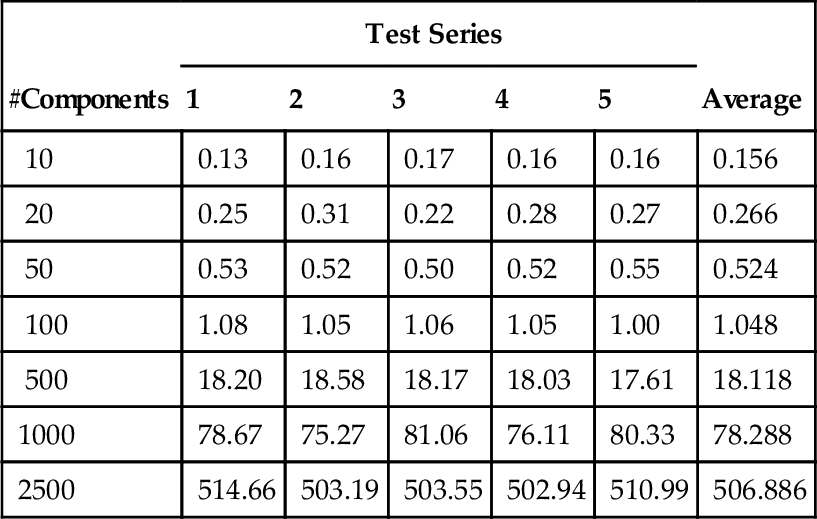
PowerLoom provides good query performance with respect to execution time. To evaluate performance for larger systems, some test series were executed. The tests included the implementation of the architectural rules for layers as discussed above. The checked models were UML design models and a layered architecture defining three layers with strict layering. The design models consisted of a defined number of components as depicted in Table 7.1; for each test series, randomly generated models of different sizes were generated. In addition to the components, the same number of interfaces was generated that provided and required relations in such a way that components were providing one to two interfaces and requiring two interfaces on average; these connected components and interfaced randomly. Moreover, components and interfaces were uniformly distributed to packages, and hence indirectly to layers. Tests were executed on a common desktop PC.
Table 7.1
Time Consumption to Check the Architectural Rules for Layers in Design Models of Different Size Measured in Number of Components
| #Components | Test Series | Average | ||||
| 1 | 2 | 3 | 4 | 5 | ||
| 10 | 0.13 | 0.16 | 0.17 | 0.16 | 0.16 | 0.156 |
| 20 | 0.25 | 0.31 | 0.22 | 0.28 | 0.27 | 0.266 |
| 50 | 0.53 | 0.52 | 0.50 | 0.52 | 0.55 | 0.524 |
| 100 | 1.08 | 1.05 | 1.06 | 1.05 | 1.00 | 1.048 |
| 500 | 18.20 | 18.58 | 18.17 | 18.03 | 17.61 | 18.118 |
| 1000 | 78.67 | 75.27 | 81.06 | 76.11 | 80.33 | 78.288 |
| 2500 | 514.66 | 503.19 | 503.55 | 502.94 | 510.99 | 506.886 |
Measured times in seconds.
The results show that the worst-case complexity of PowerLoom in querying, which is exponential, does not affect checking the rule for layers; time consumption exhibits a quadratic growth with the size of the design model. The absolute numbers, however, show that the prototype delivers checking results in a reasonable time, at least for use cases in which checks are not permanently required (such as “in-line conformance checking” during programming).
The prototypical realization shows that, although the approach can be applied in practical relevant cases, it will be extended to support more requirements from real-life industrial projects. Currently, we are working on a better integration of third-party components into the conformance checking process that includes development of a wrapper for Java bytecode, definition of exceptions of rules, for example, to allow single (third-party) components to “violate” architectural rules, and a prioritization/classification of rules to distinguish different level of strictness for architectural rules. These features will require more information to be given in the specification of architectural rules, such as a list of exceptions or strictness classification, but will not affect the applied formalisms.
7.5.2 Future work
To further improve the practical relevance of the approach, architectural rules (and also design rules) should be defined and collected in a reusable catalogue of rules. This catalogue could be used by developers of document wrappers and would in general reduce the barriers to the application of architectural conformance checking. A reasonable starting point might be the formalization of the rules that patterns of popular pattern catalogues define (see, e.g., Buschmann et al., 1996). Of course, such general catalogues will be specialized in general in projects and companies applying them and tailoring them to specific needs. Hence, it is important that architects are equipped with good methodical knowledge and tools to specify architectural rules. What notation could be used to intuitively formulate architectural rules requires further investigation.
Checking architectural compliance and detecting violations of rules are only the first step in exhaustive conformance management tool support. Hence, this approach can and should be extended by refactoring and reengineering techniques. Given that software systems are large and inherently complex, resolving violations and re-establishing compliance are difficult tasks, too. Experiences from consistency management show that automatic resolution of inconsistencies is possible only to a certain degree and must often be complemented by opportunities to manually influence inconsistency repairing (Becker et al., 2007).
Further investigations can be made into the logical formalism that should be applied to architectural conformance checking. So far, first-order logics are applied whose principal undecidability leads to some restriction in the applied PowerLoom knowledge representation and reasoning system. There is always a trade-off between the expressiveness of the language and the efficiency of checking logical statements. We will investigate whether description logics (Baader et al., 2010) would be an appropriate alternative. We will also investigate temporal logics (Gabbay et al., 2000) that could be applied to address behavioral aspects of architectural rules more efficiently. Tools like Maude (Clavel et al., 2007), which allows rewriting logic specification and programming, could be interesting alternatives for integrating flexible logics into architectural conformance checking, especially when it comes to behavioral aspects. Maude could thus be an interesting backend implementation alternative for ArCh.
7.5.3 Summary
The proposed approach allows the realization of architecture conformance checking tools that are flexible with regard to supported meta-models and to variability of architectural rules. An implementation framework allows such tools to be easily adapted to new meta-models, such that existing compliance checking functionality can be easily enhanced to new models without the need to modify existing architectural rules. It is not only possible to easily integrate meta-models whose instances need to conform to some architectural model; meta-models for architecture description defining rules can also be easily integrated.
The solution enables the specification and checking of architectural rules with the expressiveness of full first-order logics. In combination with the easy integration of models into the process of checking, the resulting basis allows significantly more powerful support for architectural conformance checking in MDSD in the future compared with the state of the art. It can hence help better to avoid architecture erosion and the loss of quality that might come with this effect.