
16
Analyzing Product Failures and Root Causes
The root cause is the most basic causal factor or factors that, if corrected or removed, will prevent the recurrence of a problem. It is generally understood that problem identification and correction requires getting to the root cause. This chapter discusses root-cause analysis concepts, presents a methodology for root-cause analysis, and provides guidance for decision making.
Generally, product failures or faults do not “just happen.” Products fail due to “failures” in design, manufacture, assembly, screening, storage, transportation, operation, and even in repair and maintenance.
The root cause is the most basic causal factor or factors that, if corrected or removed, will prevent the recurrence of the failure. Identifying root causes is the key to preventing similar occurrences in the future.
Root cause should not be confused with symptoms and apparent causes of failure. A symptom is a sign or indication that a failure exists. For example, a symptom of failure could be a knocking noise made by a washing machine. The apparent cause may be a rocking movement of the machine itself. However, the root cause is the most basic causal factor. In the above example, the root cause could arise because a bearing in the motor is worn, due to a lack of lubricant.
Root-cause analysis is a methodology designed to help describe what happened during a particular occurrence, determine how it happened, and understand why it happened (ABS Group, Inc. 1999). The purpose of determining the root cause is to fix the problem at its most basic source so that it does not occur again, even in other products, as opposed to troubleshooting, which is generally employed to merely fix a failure symptom in a given product.
In order to understand failure and the root causes, one needs to have clear definitions of failure-related concepts. Key definitions are listed in Table 16.2.
Table 16.2 Definitions of failure-related concepts
| Failure | A product no longer performs the function for which it was intended. |
| Failure mode | The effect by which a failure is observed. |
| Failure site | The location of the failure. |
| Failure mechanism | The physical, chemical, thermodynamic, or other process or combination of processes that result in failure. |
| Fault | Event or weak process (e.g., design), which may or may not cause failure. |
| Load | Application and environmental conditions (electrical, thermal, mechanical, and chemical) which can precipitate a failure mechanism. |
| Stress | Intensity of the load at the failure site. |
16.1 Root-Cause Analysis Processes
Only when investigators truly understand the question, “why a failure occurred,” will they be able to specify proper corrective measures. A well-structured root-cause analysis will provide added benefits over time by focusing resources on preventing failures.
Figure 16.1 is a flowchart of the root-cause analysis methodology. The process begins by establishing a root-cause culture within the organization, which must be prepared to effectively and efficiently investigate and correct failures. This preplanning phase involves preparing root-cause analysis methodologies and procedures that are specific to the organization and its products. Once a failure incident occurs, the root-cause investigation begins with data collection and assessment of immediate cause(s). Analysis techniques to hypothesize root causes include formal evaluation methods, such as Ishikawa diagram, failure modes and effects analysis, and fault tree analysis. The hypotheses formulated are then assessed based on the evidence gathered, design reviews and physical evaluation of the failed system. Root-cause identification and the development of corrective actions are then conducted. Finally, the implemented corrective actions are assessed with emphasis on cost and benefit analysis.

16.1.1 Preplanning
The preplanning establishes the investigation procedures and teams that can be activated as soon as an incident occurs. The goal is to introduce foresight and execution activities that will make failure analysis effectively prevent equipment failures and lessen the consequence of failure.
Preplanning begins by establishing a root-cause culture with management support and responsibilities, through awareness and education. It is essential that management commits to support root-cause analysis. The organizational or corporate culture must provide an environment where employees are encouraged to report faults, and where suitable mechanisms have been implemented to evaluate existing and potential problems.
Procedures to report product failures should be defined, such as verbal and written notification reports. The use of an event-reporting format can help bound the potential problem and determine the effort required for problem resolution (Mobley 1999). The incident report form should specify the person reporting the incident, the incident location and date, product or system affected, and any photographs, probable cause(s) perceived and any corrective actions taken. The recorded information on the failed product should be confirmed with the customers, as appropriate. These steps are to ensure that the appropriate product and failure mechanism is being investigated and that basic information on the circumstances of the event is not lost.
A classification system of failures, failure symptoms, and apparent causes should be developed to aid in the documentation of failures and their root causes, and help identify suitable preventive methods against future incidents. By having a common classification system, it may be easier for engineers, designers, and managers to identify and share information on vulnerable areas in the design, manufacture, assembly, storage, transportation, and operation of the product. Broad failure classifications include product damage or failure, loss in operating performance (e.g., deviation in product quality, plant production, or capacity rate) or economic performance (e.g., high production or maintenance cost), safety (e.g., events that have the potential to cause personal injury), and regulatory compliance (e.g., safety, health, or environmental compliance). Failures categorized as product damage can be further categorized according to the failure mode and mechanism. Different categories of failures may require different root-cause analysis approaches and tools.
Simple failures do not necessarily mean simple problems. For instance, even a simple problem may require investigating shipping, handling, assembly, and usage processes and conditions. Thus, before starting root-cause analysis, a team of investigators needs to be formed. An ideal root-cause analysis team consists of a principal analyst, experts, and the vendors of the failed product. Diversity among the team members is essential, and the respective team experts' backgrounds should be in relation with the issue being analyzed. Training will also benefit those who identify and report faults, by helping them to understand their role in the root-cause analysis process. Managers, who will use the results of the investigation, should understand the vocabulary, develop meaningful expectations from root-cause analysis training, and an understanding of the long-term benefits of fault identification and correction (Wilson et al. 1993).
Analysis strategies and procedures should also be defined, including when root-cause analysis should be performed (i.e., For every failure? Repeated failures? For which type of detected faults?). Answers to these questions may depend on the impact of the failure, in terms of cost, reliability requirements for the product category (e.g., defense and medical electronics), customer, and scheduling. Based on these considerations, failures or faults can be prioritized.
Other procedures that can be identified in the preplanning phase are the root-cause hypothesization techniques (e.g., failure modes, mechanisms, and effects analysis [FMMEA], fault tree analysis [FTA]) that are most suited to investigate specific failures. Performing an FMMEA or FTA analysis for each product proactively (i.e., before any failure occurs) will help to more rapidly identify the possible root causes of a failure.
16.1.2 Collecting Data for Analysis and Assessing Immediate Causes
Once an incident has occurred, the product design, manufacturing and marketing teams must be notified based on the procedures defined in the pre-planning phase.
The first step of root-cause analysis is collecting data to understand the events that lead to the failure. The evidence gathered is used to identify the critical aspects of failure, including the failure mode, site, and mechanism, time in the life-cycle where failure occurred, length of time for the failure to initiate, and periodicity of the failure. The investigators must be confident that they have been able to identify the major contributors and potential causal factors associated with the incident. It is important to note that events are rarely caused by one causal factor.
Complete data collection may not be feasible depending on the product or the phase of the life cycle where failure occurred. For example, failures or faults detected during manufacturing may be easier to trace than failures which occur in the field. In such instances, experimental approaches may be needed to replicate the failure and to identify the root cause(s).
Data gathering must be performed as soon as possible after the event occurs in order to prevent loss or alteration of data. An interview process should be followed to gather data from people. The people to be interviewed may include personnel directly involved in the incident, supervisors and managers of those involved in the incident, personnel who have similar background and experience, and applicable technical experts (Mobley 1999). The following key questions should be answered: what happened, where (e.g., machine, system, or area) and when (time frame and sequence of events that bound the event) did it happen, what changed (e.g., equipment failure, product performance, practices, and environment), who was involved (personnel directly or indirectly involved, including supervisory and management personnel), what is the impact (e.g., in terms of injury, reliability, and finance), what is the probability of a recurrence of the event or of similar events, and whether the recurrence can be prevented (Mobley 1999). Follow-up interviews may be needed to answer additional questions that will arise during the course of the analysis.
When investigating an event involving equipment damage or failure, the highest priority is to preserve physical evidence. If possible, the scene of the failure (e.g., the failed item and the system) should be isolated from service and stored in a secure area until a full investigation can be conducted. If this approach is not practical, the scene of the failure should be fully documented before the item is removed from its installations. Photographs, sketches, instrumentation, and control settings should be documented to ensure that all data are preserved for the investigating team. Physical data includes information of parts, residues, and chemical samples. For different industries, physical data has different meanings. For example, in the automobile industry, parts can be motors, pumps, and processing equipment. In health care, parts can be medicines, syringes, and surgical tools. All documentation records, logs, data-recording results, procedures, memos, and program manuals should also be available for analysis.
16.1.3 Root-Cause Hypothesization
There are many analysis techniques available to hypothesize root causes. These techniques range from relatively simple, unstructured approaches to the more elaborate, formal evaluation methods, such as Ishikawa diagram (fishbone analysis), FMMEA, and FTA.
Which analysis techniques should be utilized is determined by the specific problem. Some techniques seem to work better than others in a particular situation. Even less structured approaches, such as intuition, experience, communication, and brainstorming, can be extremely valuable. These kinds of techniques can be faster in solving problems than structured techniques, but they have a greater degree of subjectivity, and there is a chance of identifying an incorrect root cause.
Structured approaches usually generate some logic tables or flow diagrams that help in the analysis process. Since structured methods are organized processes, they are repeatable, and provide better documentation. Some of the structured techniques are discussed in the following sections.
Once root causes have been hypothesized, additional evidence is often required to validate or invalidate the hypotheses formulated. New evidence can be gathered by conducting additional interviews, reviewing documents and procedures against standards, conducting experiments, and further evaluating physical evidence.
16.1.3.1 Ishikawa Diagram (Fishbone Analysis)
The Ishikawa diagram, developed in the 1950s, is a graphical tool to discover root cause(s). The Ishikawa diagram is also known as a “fishbone diagram” due to its shape, and also as a “cause and effect diagram” according to its function. It allows an individual or teams to identify, explore, and display the relationship between an effect and all of its potential causes. The diagram also identifies factors that can contribute to design or process improvements.
Figure 16.2 illustrates the general structure of a fishbone diagram. The diagram has two sides: “effect” and “cause.” The effect is typically on the right side at the end of the main “bone,” while the causes appear on the left side as subbones. Effects are listed as particular quality characteristics or problems resulting from work, such as problems involving product quality, cost, delivery, workplace safety, and quality control circle activities. Causes are the factors that influence the stated effect or characteristics, and are arranged according to their level of importance or detail, resulting in a depiction of relationships and hierarchies. This can help in identifying potential causes.

There are typically various subbones joining the main bone in the diagram. These are the major categories of causes to the effect. In a production process, the traditional categories are: machines (equipment), methods (how work is done), materials (components or raw materials), and people (the human element). In a service process, the traditional categories are: policies (high level decision rules), procedures (steps in a task), plant (equipment and space), and people. In both types of processes, environment (buildings, logistics, and space), and measurement (calibration and data collection) are also frequently listed.
Once the fishbone diagram is complete, one has a rather complete picture of all the possible causes. Figure 16.3 is an example of a fishbone diagram of electrostatic discharge in electronic devices. Figure 16.4 is another example of a fishbone diagram used to analyze the thermosonic ball bonding process to attach a wire inside a semiconductor component.

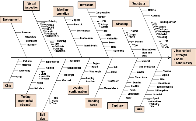
The advantage of the fishbone diagram is that it forces the investigating team to logically group and consider each of the factors identified during the investigation. This process helps uncover issues that must be addressed. Once all the factors have been identified, the team can systematically evaluate each one.
16.1.3.2 Failure Modes, Mechanisms and Effects Analysis
FMMEA is a systematic approach to identify failure mechanisms and models for the potential failures modes. FMMEA process begins by defining the product to be analyzed. The product is divided into various subsystems or levels and it continues to the lowest possible level, which is a “component” or “element.”
At the initial level of analysis, every possible failure mode and site for each component of each subsystem of the product is identified. Each identified failure mode is analyzed to determine its effect on a given subsystem and the whole product. For some components, modes of failure are easy to determine. For example, a capacitor may have three failure modes: shorts, opens, and capacitance change.
Once the failure modes are identified, the next step is to identify the relevant failure mechanisms and models that can explain why the failure manifested as a particular failure mode. Information about the environmental and operating conditions on a product helps in identifying the stresses that can propagate a failure mechanism. Information from the failure models can help prioritize the most significant failure causes.
16.1.3.3 Fault Tree Analysis
Fault tree analysis (FTA) is a deductive methodology to determine the potential causes of failures and estimate failure probabilities. It was first introduced at Bell Telephone Laboratories in connection with the safety analysis of the Minuteman missile launch control system in 1962. The method was further developed at the Boeing Company in the mid-1960s. Since then, fault tree techniques have been widely used to investigate system reliability and safety.
In contrast with the “bottom-up” assessment of FMMEA, FTA is a “top-down” approach that starts qualitatively to determine the failure modes that contribute to an undesirable top-level event. FTA provides structure from which simple logical relationships can be used to express the probabilistic relationships among the various events that lead to the failure of the system. FTA is also different from FMMEA in that it focuses on identifying subsystem elements and events that lead to a particular undesired event.
The fault tree analysis begins with the identification of the top events, which are usually the set of system failure modes that could occur. Data are then obtained and analyzed to determine which faults (events) will result in the top level failure events. The faults (events) are connected to the top failure modes (events) by Boolean logical links (AND/OR gates). The process is continued for each intermediate event until all basic events (called primary events) have been developed. If a quantitative analysis is desired, failure rates for the basic events need to be determined. Then working from basic events upward, failure probability data can be determined.
A fault tree shows only the failure modes that could individually or collectively cause the undesired primary event. In some cases, probabilities can be allocated, and they may help identify more probable root causes.
16.1.4 Analysis and Interpretation of Evidence
Reviewing in-house procedures (e.g., design, manufacturing process, procurement, storage, handling, quality control, maintenance, environmental policy, safety, communication, or training procedures) against corresponding standards, regulations, or part- and equipment vendor documentation (e.g., part datasheet and application notes and equipment operating and maintenance manuals) can help identify factors that could precipitate the failure. For example, misapplication of a component could arise from its use outside the vendor specified operating conditions (e.g., current, voltage, or temperature). Equipment (e.g., assembly, rework, or inspection equipment) misapplication can result from, for example, uncontrolled modifications or improper changes in the operating requirements of the machine.
A design review should be conducted to determine the design limitations, acceptable operating envelope, and specific indices that quantify the actual operating condition of the part, equipment, machine, or process associated with an event or failure. Unless the investigators understand what the part, equipment, or process was designed to do and its inherent limitations, it may be impossible to isolate the root cause of a problem or event (Mobley 1999).
Physical evaluation of a failed part should begin with the least destructive tests to preserve evidence that might be otherwise destroyed by destructive tests. For example, for microelectronic equipment, a failed part might be inspected visually or using magnification equipment, such as an optical or scanning electron microscopy (SEM). All anomalies, regardless of their à priori relevance to the failure, are documented. The part is then characterized and parametric behavior is recorded. To ensure a nondestructive evaluation, any applied loads should be within corresponding vendor-specified maximum allowable values (e.g., voltage and current). The investigation then proceeds to minimally invasive procedures. These can include internal examination of the materials and interfaces using acoustic-, thermal-, or magnetic-based imaging techniques. The use of conditioning environments, such as imposing a specific ambient temperature or relative humidity, may be required to replicate field conditions. Examples of other physical characterization techniques include energy dispersive spectroscopy, X-ray microscopy, scanning acoustic microscopy, scanning magnetic microscopy, Fourier transform infrared spectroscopy, and atomic force microscopy.
Selection of the appropriate test sequence is crucial to minimize alteration or destruction of evidence, depending upon the failure mechanism investigated. However, at some time, destructive physical evaluation techniques will be needed, such as microsectioning and decapsulation, followed by imaging of the exposed analysis plane or conducting material characterization.
A design of experiment (DoE) approach is recommended to minimize the number of tests without losing critical evidence that could lead to root cause. It is important to consider the test sequence, sample design attributes and manufacturing process parameters, sample size for each test, loads for parameter characterization, and the location of imaging analysis planes for physical evaluation.
16.1.5 Root-Cause Identification and Corrective Actions
After the completion of data analysis and identification of all the causal factors, root-cause identification begins. At this point, each individual and groups of causal factors are investigated. By analyzing the causal factors separately and in combinations, the probability of important details being overlooked decreases.
Once the root causes have been identified, they should be categorized. Failures with severe consequences (e.g., safety) may require processes such as manufacturing and distribution to be interrupted after discovery of the failure. Depending upon the identified root cause, processes may be restarted if corrective action(s) can be implemented that will prevent the recurrence of the failure, or sufficiently minimize its impact.
In the root-cause identification process, one or more potential corrective actions that would resolve the incident are defined. These actions include a wide range of possibilities from doing nothing to replacing or redesigning the product or system. Then, the next step is to determine which of these corrective actions should be implemented. There may be constraints to a proposed solution, in terms of, for example, cost, schedule, or difficulty of implementation if the solution is too elaborate. In some instances, breaking the chain of events at any point may be sufficient. For example, enforcing the correct application of safety procedures may be sufficient to prevent accidents associated with the use of hazardous equipment, although a corrective action that eliminates the root cause could involve the redesign of the equipment or process during which the accident occurred.
Many of the failures or events having a direct impact on production require immediate corrective actions that will minimize the system's downtime. As a result, temporary corrective actions, or immediate corrective actions, are often required to permit resumption of production. However, temporary solutions may not be financially justifiable over the “long haul.” The rationale for any decision must describe the limitations or restrictions that the partial correction will have on equipment reliability, plant performance, life-cycle costs, schedule, and other factors of plant operation and maintenance.
Not all of the actions are financially justifiable. In some cases, the impact of the incident or event is lower than the cost of the corrective action.
Although the temporary solution is often unavoidable, every effort should be made to implement permanent corrective actions. The goal is to eliminate all negative factors associated with the event or incident. While there generally is a corrective action that meets this goal, the challenge is to find the best acceptable action that also is cost effective.
A cost–benefit analysis serves to compare the cost with the benefits (including risk) derived from the corrective actions being considered. A cost-benefit analysis is simply a direct comparison of the actual total costs associated with the activity with the benefits to be derived from the change. The cost–benefit analysis contains three parts: cost analysis (quantify costs), benefit analysis (quantify benefits), and cost-benefit comparison. The analysis should include the effect of the problem on downstream production facilities. For example, a problem in one area of the plant generally has direct impact on all downstream plant areas. The loss of revenue, potential increase in conversion costs, and reluctant benefits of the corrective action on the downstream areas must be considered in the cost–benefit analysis. A full cost-benefit analysis should be conducted before recommending a course of action.
The cost analysis consists of two parts. The first part quantifies the impact of the problem, incident, or event on the process. The impact must be defined in financial terms rather than in terms of delays, downtime, and other traditional tracking mechanisms. The second part of the analysis defines all direct and indirect costs associated with actually implementing the recommended corrective actions and the benefits (in terms of dollars) from the correction actions.
The benefit analysis defines the benefits derived from implementing specific corrective actions. In root-cause analysis, the goal is to quantify the actual improvement to ensure that the potential benefits are real and significant. Benefits generally can be quantified as improvements in process-related costs, increased revenue generation, and cost avoidance of maintenances and liability.
The format of the benefits analysis should mirror the cost categories (e.g., material and labor costs) so that a comparison can be made. After a valid corrective action is implemented, there will be a measurable improvement process-related cost.
One possible benefit is a reduction in the total production and maintenance costs per unit. In some cases, this improvement may occur simply because the capacity of the replacement machine is greater than the one placed. This increase in capacity should reduce the total cost per unit because greater volume is produced. In addition to the capacity gain, the increase in availability has the additional benefit of reducing the cost per unit of both production and maintenance. Increased capacity, as discussed in the preceding paragraphs, is a major benefit that may result from implementing corrective actions. If there is a market for the additional product, this increased capacity will also provide additional revenue for the plant. A second type of benefit that should be considered is cost avoidance (e.g., risk of failure) or the eliminating of unnecessary or excessive costs, such as high maintenance costs created by a machine with a history of chronic problems. To establish this type of benefit, the cost history of the machine needs to be gathered. These data will provide the reference for existing costs. Then the projected costs will be calculated. Using the vendor's recommendation for routine maintenance and upkeep, along with the internal labor and material costs, the annual and lifetime costs of the upgrade or modification can be calculated.
Once the costs and the benefits have been quantified, an assessment should be made to determine the value of the potential corrective actions. Although different companies have different payback periods, the cost–benefit analysis must clearly show that the recommended corrective action will offset incurred costs and generate a measurable improvement over this life cycle. In general, the cost portion should include 3–5 years of historical costs, and the benefits should be projected over an equal stated period. This method will provide a more accurate picture of the real life-cycle improvements. A valid action will result in greater benefits than the costs.
16.1.6 Assessment of Corrective Actions
Once the corrective action has been approved and implemented, the final task in a root-cause analysis is to verify that this action actually corrected the problem.
Feasibility, in terms of technical difficulty and time of implementation, and manufacturability are factors that should be considered in evaluating the effectiveness of a solution. In addition, the completeness of the solution is critical. For example, revising procedures may not be a complete solution if personnel do not follow the procedures, and a more complete solution may require staff training on the revised procedures and verification that they are observed. The intended scope of the solution should be clearly understood, in terms of its specificity or generic impact. For example, training may focus on the proper use of manufacturing equipment, or on the overall manufacturing process (Wilson et al. 1993). Furthermore, both the long- and short-terms effects of the solution should be considered. For example, if training is part of the solution, its implementation, on either an isolated or continued basis, and personnel turnover, would impact on the long-term effectiveness of training.
Although compliance with standards or regulations is a well-defined indicator of the solution's acceptability, it does not guarantee its suitability.
16.2 No-Fault-Found
No-fault-found (NFF) implies that a failure (fault) occurred or was reported to have occurred during a product's use. The product was analyzed or tested to confirm the failure, but “a failure or fault” could be not found.
A failure in a product occurs when it no longer performs its intended function (Thomas et al. 2002). An intermittent failure can be defined as failure for a limited period of time, and then recovers its ability to perform its required function (IEEE 100 2000). The “failure” of the product may not be easily predicted, nor is it necessarily repeatable. However, an intermittent failure can be, and often is, recurrent.
Intermittent failures can be a cause of NFF occurrences in electronic products and systems. NFF implies that a failure (fault) occurred or was reported to have occurred during a product's use. The product was analyzed or tested to confirm the failure, but “a failure or fault” could be not found. A common example of the NFF phenomenon occurs when your computer “hangs up.” Clearly, a “failure” has occurred. However, if the computer is rebooted, it often works again.
Terms related to NFF include trouble-not-identified (TNI), cannot duplicate (CND), no- trouble-found (NTF), or retest OK (RTOK) (IEEE 100 2000; Johnson and Rabe 1995; Kimseng et al. 1999; Maher 2000; Pecht and Ramappan 1992b; Sorensen et al. 1994; Thomas et al. 2002). These terms can be defined as follows:
- Trouble Not Identified (TNI). A failure occurred or was reported to have occurred in service or in manufacturing of a product. But diagnostic testing could not identify the exact problem.
- Cannot Duplicate (CND). Failures that occur during manufacture or field operation of a product that cannot be verified or assigned
- No Problem Found (NPF). A problem occurred or was reported to have occurred in field, but the problem was not found during verification testing.
- Retest OK. A failure occurred or was reported to have occurred in a product. On retesting the product at the factory, test results indicated that it was OK.
The commonality of these terms is that a failure may have occurred but cannot be verified, replicated at will, or attributed to a specific root cause, failure site, or failure mode. In this chapter, we will use the generic term NFF.
The impact of NFF and intermittent failures can be profound. Due to their characteristics, manufacturers may assume a cause(s) rather than spend the time and cost to determine a root cause. For example, a hard drive supplier claimed NFFs were not failures and allowed all NFF products to be return back into the field. Later, it was determined that these products had a significantly higher return rate, suggesting that the NFF condition was actually a result of intermittent failures in the product. The result was increased maintenance costs, decreased equipment availability, increased customer inconvenience, reduced customer confidence, damaged company reputation, and in some cases, potential safety hazards.
NFF and intermittent failures have been reported in the automotive, avionics and telecommunications, computer, and consumer industries where they represent a significant percentage of reported warranty returns and field returns (Chan and Englert 2001), resulting in significant costs. The percentage of NFF and intermittent failures varies with the industry and products. For example, Sorensen (2003) stated the occurrence of intermittent and NFF failures on military aircraft can be as high as 50% percentage based on information from Defense Electronics Magazine.
An avionics field failure study, conducted in 1990, showed that NFF observations of electronics in avionics systems represented 21–70% of the total failures depending on the application (Sorensen 2003). NFF observations reported by commercial airlines and military repair depots have been found to be as high as 50–60% (Pecht and Ramappan 1992b).
Ford's thick film ignition (TFI) module may well be the most widespread intermittent fault problem ever reported. The failed TFI module could cause the vehicle to stall and “die” on the highway at any time (Castelli et al. 2003). However, the failed ignition modules often passed the required engineering tests established to reflect the design intent. In October 2001, Ford agreed to the largest automotive class-action settlement in history, promising to reimburse drivers for the TFI that could cause their cars to stall.
Kimseng et al. (1999) studied an intermittent failure in digital electronic cruise control modules (CCM) used in automobiles. This intermittent failure was corroborated by the fact that 96% of the modules returned to the vehicle manufacturer due to customer complaints operated properly and passed the bench tests. Kimseng concluded that the tests conducted by the vehicle manufacturer on returned products were not representative of the actual automotive environments, nor were they conducted in a manner to assess actual failures. This inappropriate testing may also lead to the high percentage of NFF.
An NFF implies that a failure was reported to have occurred during a product's use, but upon subsequent use, analysis, and/or testing, the failure was no longer observable. An intermittent failure is a failure of a product function or performance characteristic over some period of time, followed by the subsequent recovery, generally without any known external corrective action. Intermittent failures are thus common causes of NFF. A typical NFF situation occurs when the user of a product under warranty reports an intermittent failure, but the manufacturer's tests of the returned product cannot detect failure or faults in the product.
In many companies, the NFF category does not constitute a product failure statistic, because it is not considered that a failure has occurred. In some cases, the manufacturer may not understand the need or have little incentive to uncover the root cause of the problem encountered by the user of the product. The impact of this lost opportunity can be profound and generally leads to increased product cost due to extra shipping costs, warranty, and diagnostic and labor time. In addition, there can be unknown reliability and potential safety hazards of this product if the NFF product is put back in use. In addition, a high NFF rate in a product can cause customer inconvenience, loss of customer confidence, and can damage a company's reputation.
The cause-and-effect diagram is an efficient approach to analyze NFF observations in removed or returned electronic product from the field. Factors to be considered include people-related causes, such as communication and knowledge of products and equipments, capability of test equipments, test environment and test conditions, test methods, and materials related causes. Using such diagrams, the engineering team can identify the potential causes for the occurrence of intermittent failures or NFF, and isolate the most probable cause by conducting specific tests based on the possible failure mechanisms. The test results can be fed back to manufacturing, design, and logistics support teams to improve product reliability.
The cause-and-effect diagram is also an efficient approach to analyze intermittent failure observations in electronic products. The major causes of intermittent failures in electronic assemblies can be placed into four categories: printed circuit board, connectors, components and component–PCB interconnects, and specific failure mechanisms in each category that are prone to cause intermittent failures in electronic assemblies can be identified. The characteristics of intermittent failures can be summarized as unpredictable, unnecessarily repeatable, and often recurrent. As with NFF, root-cause analysis of intermittent failures can help in manufacturing and design. The analysis can also be used to help tailor tests to locate the intermittent failures in the product qualification process.
It is a good business and engineering practice to start with the premise that field returns are field failures, unless some alternative reason can be verified. It must not be assumed that a returned product that passes tests is necessarily free from faults. Companies should start with the premise that field returns are field failures. NFF statistics should not be used to ignore, mitigate, or transfer the field return problem to a nonfailure status. Once this premise is accepted, then the comprehensive cause-and-effect diagram can help identify all the possible causes for a field failure.
16.2.1 An Approach to Assess NFF
To evaluate all the possible causes of intermittent failures and NFF, a systematic method is required. One such systematic method is the development of a cause-and-effect diagram or Ishikawa diagram or fishbone diagram (Ishikawa 1985). This diagram is a graphical tool which allows an individual or team(s) to identify, explore, and display the relationship between an effect and all of its potential causes.
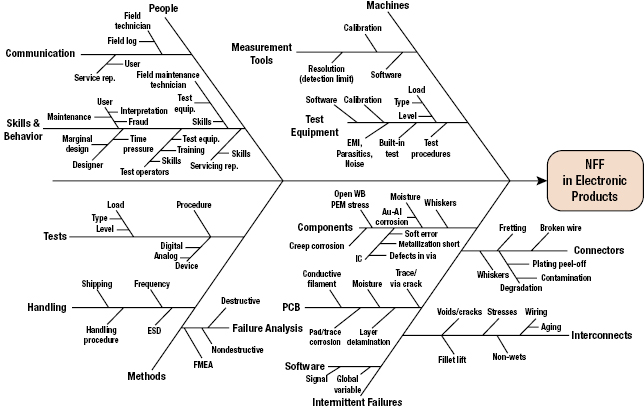
The general causes of NFF can be categorized into people (human), machine, methods, and intermittent failures. In each category, the causes are further broken down into subcategories. For example, people causes are subdivided into communication, skills, and behavior. Machine causes are subdivided into measurement tools and test equipments. Methods causes are subdivided into test methods, handling methods and failure analysis methods. Figure 16.5 is a fishbone diagram for NFF in electronic products. Intermittent failure causes are grouped under five categories: PCBs, components, interconnects, connectors, and software. There may be other categories and subcategories based on the specific product and its life-cycle profile.
16.2.1.1 People Category
Lack of skills or proper behavior of engineers, maintenance personnel, and technicians can contribute to NFF. For example, “sneak circuits” are well-known electrical design causes of latent failures. A sneak circuit is an unexpected path or logic flow within a system which, under certain unique conditions, can initiate an undesired function or inhibit a desired function. The path may arise from hardware, software, operator actions, or combinations of these elements. Sneak circuits are not the result of hardware failure but are latent conditions, inadvertently designed into the system, coded into the software program, or triggered by human error. These conditions generally require rigorous system-level tests to uncover (OPS ALACARTE Company 2006).
Communications can also precipitate NFF observations. For example, consider the customer of a car that experiences an intermittent failure. The customer reports this problem to the service depot, where the service clerk documents the problem in a service request. At this step alone, people's ability to communicate, understand, and summarize the problem, as well as the condition leading to the problem, play a key role in its correct documentation of the problem. This includes the ability of the customer to clearly explain the problem, the service clerk's ability to understand the customer's problem, and the service clerk's ability to document the problem correctly. Without correct problem identification, the service technician could come to the erroneous conclusion of NFF, even if the problem actually exists.
NFF observations can also occur by people driven by warranty or insurance claims, who replace multiple items to repair one fault or resort to fraudulent reporting of a problem that never occurred. In some cases, car dealers may replace multiple subsystems under warranty to find a problem. Those subsystems that were removed but had not failed will be identified as NFF when tested.
16.2.1.2 Machine Category
The limitations of test equipment and measurement tools can lead to the conclusion of NFF. For example, limits on measurement resolutions and measurement intervals can result in the inability to detect intermittent failures. In addition, the incapability of test equipment to simulate the actual loading conditions (e.g., vibrations, temperatures, and human operations) exhibited in the field can also contribute the NFF conclusion.
The regular and proper calibration on equipments is also the key to avoid NFF conclusions. Without accurate, capable, and reliable test equipment and measurement tools, the failed products from the field may pass bench tests.
16.2.1.3 Method Category
An inadequate or improper test procedure may lead to NFF. For example, complex products such as microprocessors may not be 100% testable if the allowable test time is too short. In addition, if the combinations of diagnostic test conditions (e.g., temperature, humidity, and vibration) are different from the field conditions where failure occurred, the failure may not be duplicated. A failure can occur due to a unique combination of loading conditions. Thus diagnostic tests may require the combined loading conditions that can occur in the field.
Properly handling the returned electronic hardware is also a key to detect NFF conditions. Handling methods should follow the established procedures in preventing uncontrolled effects. For example, anti-electrostatic discharge (ESD) packages are required for ESD sensitive products. To prevent deformation due to handling, the vibration environment should be well controlled. Clean room storage may be also necessary for debris sensitive products. Improper handling can both “heal” some failure mechanisms and induce problems that can mask the real problem reported in the field.
The failure analysis methods also play a key role in the verification of failure. Failure analysis should include nondestructive methods followed by destructive analysis as needed. Before embarking on failure analysis, it is good practice to develop a FMMEA document (Ganesan et al. 2005a; Mishra et al. 2004). Incomplete or insufficient failure analysis can lead to erroneous conclusions.
16.2.1.4 Intermittent Failure Category
Intermittent failure is one of the main causes of NFF. Intermittent failures in products can be caused by software or hardware. For example, if a global variable is read and rewritten over another global variable, a miscalculation can arise and lead to product failure (Boehm 2004). However, when the global variables are reset, perhaps upon rebooting the computer, the product can return to normal function. Intermittent failures of hardware, for example, electronic assemblies, can be divided into four categories: printed circuit board, components, connectors, and interconnects. In each category, the causes can be furthered subdivided as shown in Figure 16.6.

16.2.2 Common Mode Failure
Reliability is a key issue in critical applications such as aircraft control systems, and nuclear power plants. It is imperative that systems used in these applications perform reliably for a specified time. To increase the reliability of such systems, redundancy is commonly employed. Redundancy can be at component level or at system level. In spite of redundancy employed at various levels, systems still fail. The failure is due to common mode failures (CMFs).
CMFs occur when a single root cause, with the help of some dependencies between the components in a system or systems themselves, causes failure in multiple components or systems. Thus, an apparent “fail-safe” redundant system can easily fail within a short period of time. Such failures can be catastrophic especially in case of critical applications as mentioned earlier. It is therefore necessary to design these systems taking CMF causes and interdependencies into account.
A very well-known example of a CMF is the massive fire of 1975 at the Browns Ferry nuclear power plant in Alabama, USA. The source of the CMF observed in this case was due to human errors. Two power plant operators used a candle to check for air leak between the cable room and one of the reactor buildings. The reactor building had a negative air pressure. Due to this negative pressure, the candle's flame was sucked along the conduct, and the methane seal for these conducts at the walls, caught fire. More than 2000 cables were damaged, including those of automatic emergency shutdown systems and of all manually operated valves except four. Thus, it can be seen in this case that one root cause, that is, using fire inside the reactor, along with coupling factors such as location of all the cables along with the negative pressure resulted in simultaneous failure of different devices in the reactor.
This section discusses the various sources of CMFs in redundant systems with emphasis on electronics systems. Various analysis tools and models to predict and analyze CMFs are presented along with several strategies that can be employed to reduce the occurrence and impact of CMFs in redundant systems. Finally, a case study of CMFs in avionics industry is discussed.
16.2.3 Concept of Common Mode Failure
CMF, in its simplest form, is defined as a failure that occurs when a single fault results in the failure of multiple components. The failure of these components may be simultaneous or over a short period of time.
CMF is a special class of dependent failures. In most of the current complex systems, different parts or components have interdependent functionality. This means that functional performance of one part/component determines the functional performance of other part/component. Thus, there is dependence between different parts/components of a system. This is not restricted to a single system. In some critical applications, such as aviation and nuclear power plants, to ensure reliable function of a system, more than one system are connected in parallel to form an overall redundant system. There is also interdependence between these systems in parallel, such as shared load and shared power.
In complex systems, reliability and related risk are impacted by the interfaces between components, subsystems, systems, and the environment. Thus some parts of the system depends on or interacts with another part of the system. Failures arising from dependencies are often difficult to quantify and model. Consider A as failure of one of the parts/components in a system and B as failure of another part/component. Dependent failure occurs when both the failure events A and B occurs simultaneously or within a short period of time (Mauri 2000). The probability of this happening is given by conditional probability as follows:
Here, P(A) and P(B) are the probabilities of A and B, respectively and P(A|B) is the conditional probability that simply states that probability of failure event A occurring given that the failure event B has occurred. If one assumes that there is no interdependence between different parts/components of the systems or different modules of a redundant system, that is, the failures in those parts/components are independent then the likelihood of failure events A and B occurring simultaneously is the product of individual probabilities of failure events as shown as given below
If A and B are dependent, then
In many situations, based on dependencies, P(A and B) > P(A)P(B), and we end up overestimating the reliability of the system. There are many different ways to classify dependencies (Guenzi 2010). They may be due to intended functional and physical characteristics of the system or due to external factors and unintended characteristics. Thus, we could say that dependencies are either intrinsic or extrinsic.
- Intrinsic Dependency. When the functional state of one component is affected by the functional state of another component, it is called intrinsic dependency, and this stems from the way the system is designed to perform its intended function. Following are some of the subclasses of intrinsic dependency:
- Functional Requirement Dependency. This refers to the case where the functional state of component A effects or related to the functional state or requirements of component B. Some examples are the following:
- B is not needed when A works.
- B is not needed when A does not work.
- B is needed when A works.
- B is needed when A fails.
- Load on B increases when A does not work or vice versa.
- Functional Input Dependency (or Functional Unavailability). Here, the functional status of B depends on the functional status of A. In this case, A must work for B to work. An example is the dependence of a pump on electric power.
- Cascade Failure. In this case, the failure of A leads to the failure of B. One example is that an over-current failure of a power supply may cause failure of all the components it feeds. After the power supply is made operable, the components that have been damaged by the overcurrent will still remain inoperable.
- Functional Requirement Dependency. This refers to the case where the functional state of component A effects or related to the functional state or requirements of component B. Some examples are the following:
- Extrinsic Dependency. These dependencies are not inherent to the design of the system but are physically external to the system. The following are some examples of extrinsic dependencies:
- Physical and Environmental Dependency. This category includes dependencies due to common environmental factors, including harsh or abnormal environment created by a component. For example, high vibrations of A cause failure of B.
- Human Interactions. An example is the failure of multiple components due to the same maintenance error.
Mauri (2000) has presented a table of definitions of dependent failures and its classification into common cause failures and cascade failures (see Table 16.3).
Table 16.3 Definitions and hierarchy of dependent failures, common cause failures, and common mode failures
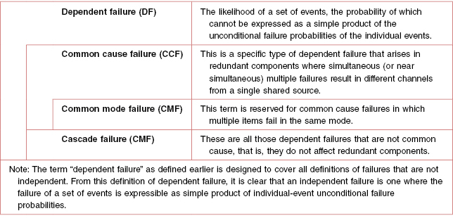
It can be seen from the Table 16.3 that CMF is a subset of common cause failure, which in turn is a subset of dependent failure. This means that all CMFs are common cause failures but not vice versa. In other words, if two or more parts/components in a system or modules of a redundant system fail via same mode then it implies that there was a common cause that brought about the CMFs. On the other hand, if two or more components in a system or modules of a redundant system face a common cause, then this does not mean that the components or modules will definitely fail in common mode. The structural integrity, design, type of components, and layout of the different components will decide whether the components or modules will fail in common mode.
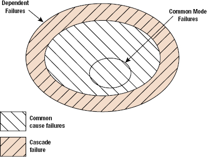
Figure 16.7 provides a graphical presentation of CMF as a part of dependent failures. Thus, now it can be inferred that a CMFs should have common cause that initiates this failure. This common cause is also known as the root cause, which through coupling factors results in failure of more than one component or module, simultaneously resulting in CMF (Figure 16.8). The root cause determines the mechanism with which CMF occurs. For example, consider a highly redundant system in a space exploration aircraft sent on a planet exploration mission. If the temperature on the planet of interest is not considered properly, then all the components used in the system will be designed for maximum temperature rating less than that is present on the planet. Thus, no matter how much redundancy is present, all the components will fail, simultaneously resulting in a CMF. In this case, temperature is the root cause of failure, and designing of all the components at the same temperature rating is a coupling factor. Root causes can be external or internal to the system. They can also arise from failures of operating equipment or human errors. For example, environmental loading is an external root cause, whereas the ill-functioning of a component in a system resulting in failures of other components is an internal root cause. Generally, four different types of failure mechanisms are recognized. They are as follows:
- Coincidence of failures of two or more identical components in separate channels of a redundant system, due to common cause (may have common failure mode too).
- Coincidence of failures of two or more different components in separate channels of a redundant system, due to common cause (may have common failure mode too)
- Failures of one or more components that result in coincidence of failures of one or more other components not necessarily of the same type, as the consequence of single initial cause.
- Failure of some single component or service common to all channels in a redundant system.
Thus, a CMF as defined by Edwards and Watson (1979) is “the result of an event, which because of dependencies, causes a coincidence of failure states of components in two or more separate channels of a redundancy system, leading to the defined system failing to perform its intended function.”

16.2.4 Modeling and Analysis for Dependencies for Reliability Analysis
Intrinsic dependencies are considered when we develop system logic models and fault tree analysis for risk and reliability analysis. Functional dependencies arising from the dependence of systems on electric power are included in the logic model by including basic events, which represent component failure modes associated with the failure of the electric power supply system. Failures resulting with the failure of another component (cascading or propagating failures) are also explicitly modeled. Human error is included as branches on event trees or as basic events on fault trees. Maintenance errors are considered in fault trees or included in overall component failure probability.
Extrinsic dependencies based on physical or environmental factors such as temperature, vibrations, and radiation, are modeled as part of the physical processes for degradation or failure. Dependent failures whose root cause is not explicitly considered are also known as common cause failures and this category can be accounted in probabilistic risk analysis by considering common basic cause event. A common basic cause event is defined as the failure of more than one component due to shared cause during the system mission. Components that fail due to a shared cause may fail in the same functional mode. CMF is the failure of multiple components in the same mode and thus is a subset of common cause failures as shown in Figure 16.7. The following are some examples of common cause failures:
- All redundant auxiliary feedwater pumps failed at the Three Mile Island nuclear power plant.
- Hydrazine leaks leading to two APU explosions on STS-9.
- Failure of two O-rings causing hot gas blow-by in the space shuttle solid rocket booster of Shuttle Flight 51L.
- Two redundant circuit boards failed due to electrostatic shock by technician during replacement of an adjustment unit.
- Worker accidently tripped two redundant pumps by placing a ladder near pump motors to paint the ceiling.
- Check valves installed backward, blocked flow in two redundant lines.
Common cause failures may also be viewed as being caused by the presence of two factors: (1) a root cause which is reason for failure of the components which failed in the common cause failure event and (2) a coupling factor which is responsible for the event to involve multiple components (Figure 16.8).
Failure of two identical redundant electronic devices due to exposure to excessively high temperatures shows that heat is the root cause and the coupling factor is that both of them are identical and are being subjected to the same harsh environment.
One simple way to model dependencies and the impact of common cause failures is the beta-factor model. Consider a simple redundancy of two identical components B1 and B2. Then we can further evaluate the failure of components as failing independently of each other and also failing due to common cause failures. Let us assume that the total component failure frequency [λT] is the sum of independent failure frequency [λI] and the common cause failure frequency [λC] over some given period. Then the β factor is defined as
Thus for this system with two identical components, the β factor system block diagram is shown in Figure 16.9.

16.2.5 Common Mode Failure Root Causes
As mentioned above, CMFs have a common cause (root cause) that initiates failures in more than one components of a redundant system. The following is a discussion of CMF root causes. The root causes can be classified into three broad categories, namely, design and manufacturing errors, catastrophic events, and human interaction errors.
16.2.5.1 Design and Manufacturing Errors
As the name suggests, these errors are induced in a redundant system due to design inadequacies and manufacturing defects. These errors are qualitative in nature, meaning that their severity can be measured using some unit. The design errors are difficult to predict as the prediction power depends on the extent of knowledge about the possible loads a system will face in its life cycle. Thus, it is hard to completely remove design errors from a system. Design errors include the following:
- Inability of a component or system to perform its intended function. Limitations on carrying out exhaustive tests or simulate actual operating conditions can prohibit detection of all the design errors.
- Inadequate, poorly designed or harmful periodic tests can precipitate errors in the design that would not have been observed in case of regular operating conditions.
- Poor optimization regarding CMFs. Protection against one CMF can increase susceptibility to other CMFs.
- Inadequate study during design procedure.
Let us look at some of the examples of design errors that result in CMFs. Consider a variation of the example provided earlier about the planetary mission. Consider a redundant system installed in a room where the relative humidity is controlled with the help of an air conditioner. Now, suppose some classes of components in parallel paths of the redundant system are designed to function properly until some relative humidity level in the room. If the air conditioning system fails, then the relative humidity level in the room will increase and if it crosses the designed limit of the components, then they will fail inadvertently. Here, the root cause is the increase in relative humidity and the coupling factor is location of all the parallel paths in the same room.
In case of high safety requirements in systems, periodic tests are carried out to ensure that all the components in the parallel paths are functioning properly. If the tests are poorly designed, in a way that some loads applied during were not considered during designing of the component, then there is a possibility of weakening of the components. Thus, the components might not be able to withstand loads or function properly when put in operation. For same components, it is possible that this will occur in more than one component, leading to CMF in a redundant system.
Similarly, if a redundant system is designed to be “fail-safe” in high temperature applications, then there is possibility of weakening of the system in a moderate to high radiation applications. For instance, if an electronic component on a board is designed to better dissipate and radiate heat to the surroundings, then the size of the component has to be increased. This will lead to reduction in physical separation of components on board. Thus, there is a possibility of more interference between the components on same or nearby boards, leading to malfunctioning of more than one component.
Manufacturing errors arise in components due to inferior quality of manufacturing processes or materials. Most of the time, these errors are due to improper technical specifications or technological errors. Manufacturing errors can affect few or all components produced. Now, if the same components are used in a system, then the errors induced during their manufacturing will precipitate and eventually lead to failure. Since the same manufacturing error is present in similar components, it is quite likely that these components will fail simultaneously or within a short period of time.
These causes can be detected and rectified to get a better redundant system. With increase in technical know-how, designers will be better equipped to model and simulate comprehensive life-cycle operating conditions for improved design of components or parts.
16.2.5.2 Human Interaction Errors
Even if a system is well designed to eliminate all design errors and perfectly manufactured to remove all the manufacturing errors, it is still prone to CMFs due to human interaction induced failures. No system is completely automatic and requires some kind of human control and interaction. For example, a person might be required to operate some control, and human activities are required for maintenance and repair of a system. Human interaction with the system can occur at various phases, such as installation, operation, and maintenance. If errors induced during these phases affect functioning of more than one component or module, then those components and modules can fail simultaneously during the system's operation period.
Systems are designed to operate at some predefined operating conditions. Designed systems are tested for reliability at those operating conditions. If an operator takes an incorrect action, then the system can be subjected to conditions different from the initially considered operating conditions during the design process. Depending upon the compliance of system design, the system will be able to withstand these conditions. If the system is not compliant enough, then it will fail.
Human errors during maintenance activities, such as improper implementation of maintenance activities and improper handling of the system can create conditions suitable for more than one component. For instance, if during handling of an electronic board with components mounted on it, a crucial component is damaged. The output for this component is used by more than one components, then those components in the system will fail, that is, will not function. Especially in case of the current high density electronic circuitry, where components with delicate structures are used, induction of failures due to human interactions is a key concern.
In case of software, human errors are the most common and important ones. Software is completely developed by humans. Any mistakes made by the programmer will lead to software malfunctioning. This is analogous to manufacturing defects. These errors are hard to detect due to the complex nature of today's software. Moreover, these errors can spread from one version of software to another.
16.2.5.3 Catastrophic Events
Catastrophic events, such as lightning, flooding, and earthquakes, can act as root cause for CMFs in electronic systems. The probability of these root causes occurring is fairly less. Moreover, catastrophic events are also random in nature. Thus, it is difficult to predict the occurrence of these events and therefore is hard to model.
Consider a room consisting of numerous servers storing critical information. If the room is at ground level, then it is prone to flooding. Now if the room gets flooded, then all the servers will go under water. Shorting of all the circuits in all the computers will occur simultaneously, and they will fail at the same time, losing all the important information. Here, flooding of the room is the root cause, and the location of all the computers in a room at lower level is the coupling factor.
Another example could be a control module on an aircraft. Consider a redundant wing control module placed at back of the plane. Thus, all the paths in the redundant system are at the same location. Suppose the components in the module are rated for a specific voltage. While passing through clouds, lightning strikes the back part of plane. If the voltage induced by that lightning is greater than that of the voltage ratings, then the components in the redundant system will fail simultaneously leading to CMF. Here lightning is the root cause, while the location of all the parallel paths of the redundant system at the same location is the coupling factor.
In case of electronic components, common examples of catastrophic events are electrostatic discharge, electrical overstress, mechanical overstress, thermal overstress. These root causes can be external or internal to the system.
16.2.6 Common Mode Failure Analysis
CMFs as discussed previously are the type of failures in which one cause results in failures of more than one system either simultaneously or within a short period of time. CMFs become especially critical in redundant systems where safety is the key issue. An example of this could be various control systems on an aircraft. Thus, it is imperative to analyze the possible CMFs in the earlier stages so that effective preventive actions can be taken well in advance. This section discusses the different models employed to analyze CMFs.
16.2.6.1 Failure Mode and Effect Analysis (FMEA)
Thus, FMEA is technique used to identify potential failure modes and evaluate the effects of those failures. This approach (see Figure 16.10) can be applied to a component, assembly, or a system. This analysis starts with an intense review of component failure modes and its effect on the assemblies and various further dependent systems. The main intention in this analysis is to determine the root cause of failures in a component that can initiate CMFs. Thus, once the root cause of failure is identified, then corrective actions can be taken so as to avoid component failures that can lead to CMFs. For example, consider a case of a redundant electronics system. In this system, electronic components are held on the same type of printed wiring board that has a high CTE mismatch with most of the electronic components. Now, if this redundant system is placed in an environment with high operating temperatures with little thermal isolation, then similar components will fail due to cracks in solders resulting in open circuit. Here, the root cause, CTE mismatch-induced stresses, in the presence of the coupling factor (location), brings about a CMF of a redundant system. Hence, it is essential to take into account coupling factors while performing FMEA. The following is the list of coupling factors that can be used in FMEA analysis (Childs and Mosleh 1999).

Common Operation Usage
- Age. The age of the components in a redundant system can act as a coupling factor in CMFs. Suppose components in a redundant system are used for a considerable amount of time and they are in the wearout phase, then there is higher probability of their failure. If similar components are used in different parallel blocks of a redundant system, then the probability of their simultaneous failure goes up, which can lead to CMF in the redundant system.
- Maturity. This is related to the compatibility issues. Suppose if worn-out components in a redundant system are replaced with new components with higher maturity level, then there is a possibility that the new components may not be compatible with the old systems. This can lead to simultaneous failure of different subsystems in a redundant system.
Shared Work Environment
- Proximity. If the different elements of a redundant system are placed near each other, then it is possible that operating conditions of one element can affect operation of another closely placed element. For instance, electromagnetic field produced by one electronic component in a system can adversely affect functioning of another electronic component. Heat produced by a high powered device can adversely affect a heat sensitive device if it is placed close to the high power producing device.
- Medium Similarity. If the surrounding medium for all the redundant element is same, then there is a possibility of simultaneous failure of different redundant elements. For example consider, a redundant control system in an aircraft is placed at the nose of the aircraft. If this system consists of components that are highly sensitive to pressure, then there is a high probability of simultaneous failure of those components. This can lead to CMFs in the redundant system. Another example could be failure of humidity sensitive components in a redundant system place in a highly humid environment.
Functional Coupling
- Same Energy Source. Suppose if the different elements of a redundant system are operating on the same energy source then in case of source failure, energy to all the elements will cease simultaneously.
- Same Input/Output. If different parallel paths of a redundant system have a common input, then in case of a false input all the element of the system will perform improperly leading to CMF.
- Same Load. In case a redundant system shares a common load, then failure in the load can lead to failure in all the paths of the redundant system.
Common Personnel
If common personnel are not used for design, installation, construction, operations, and maintenance, then there is a possibility of dissimilarities occurring, which can lead to failure precipitation in different components of a redundant system leading to CMF.
Documentation
Incomplete or incorrect procedures, displays, and drawings can lead to design defects, and defect produced during installation, maintenance in various elements of a redundant system leading to a possible CMF.
Similarity in Components
If all the components used in a redundant system are similar, then the probability of them failing simultaneously goes up as their response to the operating conditions will be similar and will also fail under same conditions.
FMEA thus can provide a tool for component selection in a redundant system, as well as provide a guideline for proper design and maintenance of the system so as to prevent or reduce CMFs. However, FMEA is not a replacement for a more detailed analysis method.
16.2.7 Common Mode Failure Occurrence and Impact Reduction
CMFs can produce failures in redundant systems that can lead to catastrophes. This is especially critical in case of applications such as airplanes and nuclear plants. Hence, it is necessary to reduce the occurrence of CMFs in such applications or reduce their severity of impact. This can be done during the initial stages of design and development. The following are some strategies that can be employed to reduce occurrence and impact of CMFs.
16.2.7.1 Fault Detection Systems
It is possible to establish defense against CMFs in systems by using programmable electronic systems. Fault detection systems are indented to detect faults in components or systems before they can cause failures, so that it increases the robustness of the system. Fault detection systems are further divided into two classes:
- Periodic Tests. Periodic tests test the correct operation of a system resource at a given time. These tests are run on power-on mode and at periodic intervals during operation. It is thus unable to detect transient faults or an error occurring between two tests. Periodic tests are basically used to detect accumulation of faults that can result in CMFs.
- Online Monitoring. This technique continuously monitors the functioning of all or part of a system. Thus, faults are detected instantaneously within a very short period of time. Thus, with a system that can effectively compare the performance of all or part of the system with some preset standard, it is able to detect any faults that might occur during operation of a system.
16.2.7.2 Separation
Separation is an effective technique that can be employed in redundant systems to reduce the propagation of failures from one function to another or one component to another. Following are some methods of separation.
Physical Separation
In this type of separation, different paths of the redundant system or different components in the same path are physically separated to avoid interaction between them that can cause malfunctioning. Consider a component that produces large electromagnetic field around it. If another component that is more susceptible to electromagnetic field is in vicinity of this component, then there can be some malfunctioning of the component that is sensitive to electromagnetic field. Thus, in order to avoid this interference effect, it is necessary to separate these components with proper distance.
Electrical Isolation
It is necessary to have electrical isolation between various paths of redundant systems to avoid failure due to events such as sudden increase in current through the paths. If all the paths are electrically connected, the sudden rise in current will affect similar components that are sensitive to high currents in the different parallel paths. This can result in CMF in the redundant system.
Power Supply Separation
If all the channels of a redundant system are connect to a same power supply, then in case of power supply failure all the channels in the system will fail leading to CMF of the system. To avoid this, different channels of the redundant system can be put on different power supply thus ensuring that at least one of the channel will work in case of a power supply failure.
16.2.7.3 Diversity
Diversity implies variation in different components, subsystems of multiple path redundant system so as to reduce the occurrence of CMF in such systems. Diversity reduces the probability of simultaneous failure of similar components due to common root cause. The following are different types of diversities that can be employed so as to reduce CMFs.
Design Diversity
Different designs for different paths in a redundant system can reduce CMFs that occur due to design flaws. If a similar design in terms of layout, placement of components, and so on is employed for all the paths in a redundant system, and if there is an inherent flaw in that design, then there is a high chance that all the paths will fail simultaneously, causing CMFs in the redundant system. Thus, different designs for the paths can reduce the susceptibility of the redundant system to CMFs. For example, digital instrumentation and control systems in nuclear power plants employ independent protection systems.
Functional Diversity
Functionality of components in a redundant system depends upon the operating conditions and environmental conditions. Thus if similar kinds of components are used in a system, then under certain operating conditions or environmental conditions that cause malfunctioning of the components, it will result in simultaneous or nearly simultaneous failure of all the similar components leading to CMF in the system. Functional diversity consists of different parameters, different technologies, and so on.
Manufacturing Diversity
One of the major sources of CMFs is manufacturing defects induced in the components or assemblies. Thus, if all the components in all the channels are from the same manufacturers that have manufacturing defect, then there is a high probability that all the components in different channels will fail, simultaneously leading to CMF in the system. Thus, using components in different paths from different manufacturers reduces the probability that the components have similar manufacturing defects that can lead to CMFs. For example, most airplane manufacturing companies like Airbus and Boeing use components designed and manufactured by different equipment manufacturers.
Equipment Diversity
If similar equipment is employed in steps such as maintenance, testing that can produce defects in components, then it is possible that components in all the paths of a redundant system will incept defects from the equipment. These defects can nucleate during the operation of the system leading to simultaneous failure of the components in different paths of the redundant systems. This can lead to CMFs in the redundant system. For example Airbus (EADS) uses one channel for control and another channel for monitoring in their flight control system.
Signal Diversity
If all the channels of a redundant system use same input signal, then in case of an incorrect signal, all the channels will fail or operate improperly. This is nothing but CMF that occurs due to wrong input signals.
Human Diversity
It was explained earlier that one of the sources of CMFs is human interaction-induced defects. By employing human diversity, it is possible to reduce these defects. Human interaction effects vary during different phases in the life cycle of a system. Thus, one can have different groups working on the same module or subsystem.
16.2.7.4 Fail-Safe Design
The notion of fail-safe is defined here as a theoretical condition that is attained if a safety function were to remain unchanged in case of a failure in the power supply or in a component contributing to this function. A fail-safe design will ensure that short-circuits, open-circuits, and all such sources of failures are minimized to ensure that the safety function of the system is not altered. Moreover, dynamic signals are preferred over static signals. The earlier-mentioned methods, such as FMEA and fault tree and event tree analysis, can also be used to develop a fail-safe design.
16.2.7.5 Protection against Environmental Aggressions
The system must be designed in such a way that CMFs due to environmental aggression, such as lightning, voltage surges, or flooding, can be reduced. For this purpose, methods such as electrical isolation or mechanical shielding can be employed.
16.2.7.6 Reducing Uncertainty about Common Mode Failures
The ultimate goal for any system is for it to perform exactly to its specifications, producing the correct output reliably for its intended life. If the purpose of the system is to process information and output a solution based on the inputs, given an ideal system, one input would result in the exact same output an infinite number of times or until the useful life of the system had expired. Similarly, the system would be expected to produce the correct output given an infinite number of varied inputs during its life. In other words, the goal is for the system to be perfect.
While perfection such as this is almost always desired, it is very difficult to attain. This presents the following design problem: how do you design a system to be as close to perfect, or error-free, as possible? This is the situation with many of the systems used in the fields of avionics, automotive, and nuclear power control. In these systems, even minor failures cannot be tolerated, because the consequences of the failure could be very severe.
Error reduction or elimination is a complex engineering problem on its own, but alone it is not enough to satisfy the safety and performance standards of many systems used in avionics, automotive, and nuclear control applications. In order for these systems to be effective, they have to not only be error free, but also resilient and fault-tolerant. Being fault-tolerant means that the system is able to withstand some unanticipated event, and remain operating without error. In these industries, many systems are only useful if there is no uncertainty involving their operation, and if they are error free and fault tolerant.
Although these systems can be resilient and can possess as few errors as possible, it is still very difficult to eliminate CMF. CMF is defined as: “Failure of two or more structures, systems or components in the same manner or mode due to a single event or cause.” The susceptibility of these systems to CMF arises from the interdependence of one system on many others. This interdependence causes problems when one component of the system fails, because it in turn may cause all the components dependent on it to fail. Consider the guidance and control system in an aircraft: a failure of the component powering all of the guidance and control systems would result in a failure of all of the components depending on power. If this system is not designed to withstand this example of CMF, then the result would be disastrous.
16.2.7.7 Designing to Reduce Uncertainty
In order to design the optimal system, it is necessary to understand the source of the problem that causes an error. In many systems, the source of the problem arises from uncertainties within the system's operation, which eventually result in aberrant or incorrect outputs, also known as errors. These uncertainties, which must be minimized in order to achieve the optimal system, show up in the form of anomalies.
An anomaly can be described as an event that occurs in the execution of software that causes the output of the software to differ from what the result would have been without the anomaly being present. More simply, an anomaly is an unexpected error in a part of the system that causes an incorrect output. Anomalies are usually present in three forms: (1) internal defects present in the code, (2) ambiguities and errors in specification, and (3) external events (not involving an error in the code) that modify either the input or the output of the code. In order to reduce the uncertainty of either category of anomaly occurring, the system must be designed to deal with each type individually. To design the systems with the least amount of uncertainty involving the occurrence of CMFs, it is important to understand how the design of the systems reduces the effects of the three types of anomalies.
The following four systems illustrate how proper design can limit the uncertainty about CMF. They also show what design techniques are used to counter the effect of each of the three types of anomalies.

In this system, the input signal is received by program 1, which performs the necessary function producing the output. This system is an example of a system that has a very high uncertainty about the possibility for CMF. It is obvious that any anomalous events that occur during the operation of this system, either an error in program 1's code, an error in specification, or an external event could all singularly cause the system to output an incorrect result, and thus fail. The use of this system in avionics would not be tolerable because there is obviously no design techniques used to reduce the effect of any possible anomalies.
One technique that is used to reduce the uncertainty involved in the system and to reduce the possibilities of CMF is replication. A system designed using replication is shown in Figure 16.12.
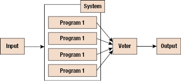
This system is much improved over the system shown in Figure 16.11. The goal of designing using replication is to achieve fault tolerance using many identical copies of the necessary program. This design lessens the chance that an external event anomaly, such as a hardware failure, will cause failure of the entire system. Even should one copy of the program become corrupted, the remaining replications of the program should still output the correct result.
Since this system produces four separate outputs, a voter is used to determine which output is the correct one, should there be a discrepancy. In most cases, the voter will compare the output from each copy or program 1 and accept the majority answer as the correct one. This is reasonable because it is unlikely that all of the replicas will fail at the same time in the same way. The voter could also identify errors in specification by comparing the outputs to an expected range of outputs. If the outputs all lie outside of the expected range, there may be an anomaly in the form of a specification error.
While replication increases the resiliency and fault tolerance of the system by a great deal, it fails to counter all possible anomalies, and thus leaves some amount of uncertainty. Although this system is resilient against some forms of external events, the resilience could be greatly improved if the replicas of the program were stored in spatially separate and isolated locations. This would lessen the likelihood of damage to one area of an aircraft, rendering all of the replicas of the program as failed.
The other uncertainty and the most severe is the susceptibility to CMF. Protection against two out of the three anomalous events affords the system nothing if the third kind arises and causes total failure. This event is an error in the code of program 1. The replications of program 1, even in spatially separate locations, do nothing to counter the effects of an error in the code. Since an error in the code will be present in all the replicas of program 1, an input that causes an error in one replica will similarly cause all of the programs to produce an identical, incorrect output otherwise known as a CMF. In his case, the voter receives four identical outputs, and either assumes that they are all in agreement so they are all correct, or decides that none lies within the range so none of them is correct.
Either way, the system fails to achieve its function without the correct output. This failure is very severe because one error in the code of program 1 can disable the entire system, and with the programs used in these systems, it is nearly impossible to remove all of the errors present. In order to reduce the uncertainty about CMF and the system, the system is designed with diversity and replication.
In this final example, diversity is used to create a more fault tolerant system than the system with only replicated programs. Diversity in the programs provides protection against the CMFs that the previous system was susceptible to. In a diverse system, critical components are created in different ways, with the least number of similarities between the two.
The goal of a diverse system is to eliminate the possibility of CMF between the diverse components of the system. Consider the system shown in Figure 16.13. The diversity is made possible by “implementing the individual functions in a diverse manner.” This system exhibits both replication and diversity, therefore countering all three types of anomalies that may arise during the life of the system.

The first type of anomaly, internal defects in the code, will not be present in all of the varied versions of the program (the likelihood that unrelated errors in each version of the program would produce the same output are very slim). This is not to say that each varied version will be error-free. This would once again be impossible to achieve, rather the hope is that the errors made in each version do not lead to the same incorrect output for any one input, thus creating a CMF.
The second type of anomaly is ambiguities and errors in specification. Once again, the voter algorithm should be able to detect outputs in the correct range, and make a guess as to in the specifications might be incorrect. Of course, the only true way to prevent this kind of anomaly from occurring is to make sure all of the specifications are correct.
The third anomaly is external events, which change the output of the program. A system employing both diversity and replication is able to handle failures of individual components, providing that there is still a majority of votes left for the voter to decide on. The resiliency of this system could also be increased by separating the differing and replicated versions spatially within the environment. In this kind of system, there are only two ways that failure can occur: CMFs between multiple, diverse programs, or errors in the voter that cause it to select the correct outputs reliably.
16.2.7.8 Simulating Errors or Faults in the System
In order to predict and reduce the uncertainty about CMF occurrence, it is helpful to set up a system and simulate multiple faults, and then analyze if the system is resilient or susceptible to CMFs. This simulation can be accomplished by a computer program using fault injection. The process begins by simulating the system without the presence of defects. Then the program randomly inserts errors in the systems' various programs and compares the output to the previous output. If the two are different, then failure has occurred.
Voas et al. (1997) present an algorithm to reduce uncertainty about CMF. The algorithm they propose calls for the execution of a set of inputs in the original run without state perturbations and the perturbed run with fault injection and the outputs for each input are temporarily stored. Then perturbed run is made with same input but with fault injection and again output is stored. The outputs from perturbed run and the original run are compared. The comparison of all perturbed outputs for a given input can help us determine if a single input common-mode failure resulted in these simulations. For a single input, if the perturbed outputs are identical and different from the original output, a single input CMF is counted.
Using this process, it is possible to predict the performance of a system in the event that anomalies are encountered, and to “fix a problem before it occurs.” The more modeling and testing that is done on a system, the greater the reduction in uncertainty. The ultimate goal of this testing is to prevent even a single failure from occurring during the operational life of the system, because it is much easier to fix a problem during simulation than when the system is in operation.
16.3 Summary
Generally, product failures or faults do not “just happen.” Products fail due to “failures” in design, manufacture, assembly, screening, storage, transportation, or operation. The root cause of a failure is the most basic causal factor or factors that, if corrected or removed, will prevent the recurrence of a problem. Getting at the root cause involves problem identification and correction requires getting to the root cause. Root-cause analysis is a methodology designed to help describe what happened during a particular occurrence, determine how it happened, and understand why it happened. Only when investigators truly understand why a failure occurred will they be able to specify proper corrective measures. A well-structured root-cause analysis will provide added benefits over time by focusing resources on preventing failures.
The process begins by establishing a root-cause culture within the organization, which must be prepared to effectively and efficiently investigate and correct failures. This preplanning phase involves preparing root-cause analysis methodologies and procedures that are specific to the organization and its products. Once a failure incident occurs, the root-cause investigation begins with data collection and assessment of immediate cause(s). Analysis techniques to hypothesize root causes include formal evaluation methods, such as Ishikawa diagram, failure modes and effects analysis, and FTA. The hypotheses formulated are then assessed based on the evidence gathered, design reviews, and physical evaluation of the failed system. Root-cause identification and the development of corrective actions are then conducted. Finally, the implemented corrective actions are assessed with emphasis on cost and benefit analysis.
NFF implies that a failure (fault) occurred or was reported to have occurred during a product's use. The product was analyzed or tested to confirm the failure, but “a failure or fault” could be not found. Intermittent failures can be a cause of NFF occurrences in electronic products and systems. NFF implies that a failure (fault) occurred or was reported to have occurred during a product's use. The product was analyzed or tested to confirm the failure, but “a failure or fault” could be not found. The general causes of NFF can be categorized into people (human), machine, methods, and intermittent failures. In each category, the causes are further broken down into subcategories. Particular categories and subcategories will differ based on the specific product and its life-cycle profile.
This chapter provides guidelines for determining failure mechanisms and root causes, including difficult NFF failures. Analysis of failure mechanisms and root causes is essential for both proper repair and maintenance, as well as product development.
Problems
16.1 What causes a product to fail? List as many causes as possible.
16.2 What is a root cause? How can physics of failure help root-cause analysis?
16.3 Describe three methodologies for root-cause analysis.
16.4 What is a cause-and-effect diagram? Draw a cause-and-effect diagram for the failure of an electronic device.
16.5 Can nondestructive testing cause permanent changes to a product? Why or why not?