
CHAPTER 8
Structural Items
Well, we can't avoid the topic of structure forever. Because you need to consider your structure from pretty much the beginning of the project, I had better add it to the first half of the book before we get too carried away! As an addition, please note the tried‐and‐true workflow is that the structure is contained in a separate model that is linked into the architectural model. However, many times you as the architect are going to lay out grids as well as add columns and some framing to get a basis of design. This chapter will cover the latter.
This chapter covers the following topics:
- Adding structural grids
- Adding structural columns
- Using structural framing
- Understanding foundation systems
- Adding structural footings
- Using structural views
Adding Structural Grids
Since we started modeling our building for this book using the architectural template, you will quickly discover that most structural items aren't loaded into our model. This is normal, as I eluded to in the opening paragraph of this chapter that the typical workflow is to link different models. There are a few reasons for this. One, the structural engineer cannot stand you touching their framing. Another reason is what we are faced with now. A structural template will be loaded with structural elements and not many architectural elements.
This chapter explores the structural world by presenting the basic functions of structural architecture. The first item you'll tackle is usually the first item in the model: structural grids. Although you add structural grids line by line, you'll soon discover that these grids are just as smart as the rest of the Autodesk® Revit® software. The starting point for all things structural is most certainly the grid. In Revit, you'll quickly find that placing a structural grid into a model isn't a complicated task. Grids are essentially placed one line at a time. Those lines you place, however, have intelligence. For example, if you place a vertical grid line called A and then place a horizontal grid line called 1 that intersects with A, you'll have a grid location. If you place a column at that intersection, the column will assume a new property called Location. That location is—you guessed it—A‐1.
Let's get started. To begin, open the file you've been using to follow along. If you didn't complete the previous chapter, go to www.wiley.com/go/revit2020ner, browse to Chapter 8, and find the file called NER‐08.rvt.
Placing a Grid
Placing a grid means drawing grid lines one by one. You can copy grids to speed up placement and array them if the spacing is regular. This task sounds tedious, but it's a welcome change from other applications that force you to create an entire rectangular grid, which you have to keep picking at until it resembles your layout. Grids are like snowflakes: no two are the same.
To place a grid, follow these steps:
- In the Project Browser, go to the Level 1 floor plan. (Make sure you aren't in the Level 1 ceiling plan.)
- Zoom in to the east wing's northwest corner, as shown in Figure 8.1.
- The Datum panel that holds the Level and Grid tools appears on both the Architecture and Structure tabs. On the Datum panel of the Structure tab, click the Grid button, as shown in Figure 8.1.
- On the Draw panel of the Modify | Place Grid tab, click the Pick Lines icon, as shown in Figure 8.2.
- Pick the centerline of the west wall (see Figure 8.2).
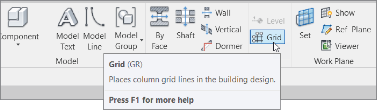
FIGURE 8.1 The Grid button on the Datum panel of the Structure tab
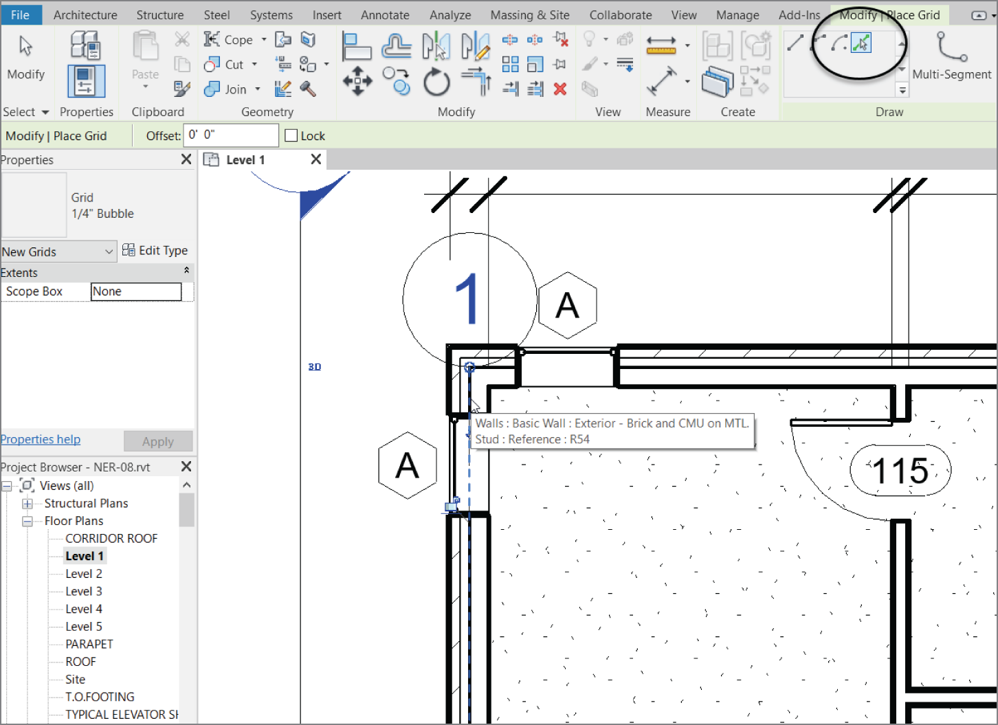
FIGURE 8.2 Your first column grid
- The grid bubble needs to be moved. Press Esc twice or click Modify (to clear the command), and then select the grid bubble. Notice the round blue grip similar to that in Figure 8.3.
- Pick that round blue grip, and drag the column bubble up about 8′ (203 mm), as shown in Figure 8.4.
- Zoom in on the south portion of the same wall.
- Select the grid. Notice there's the same grip as well as a square blue box.

FIGURE 8.3 Examining the column grid grips
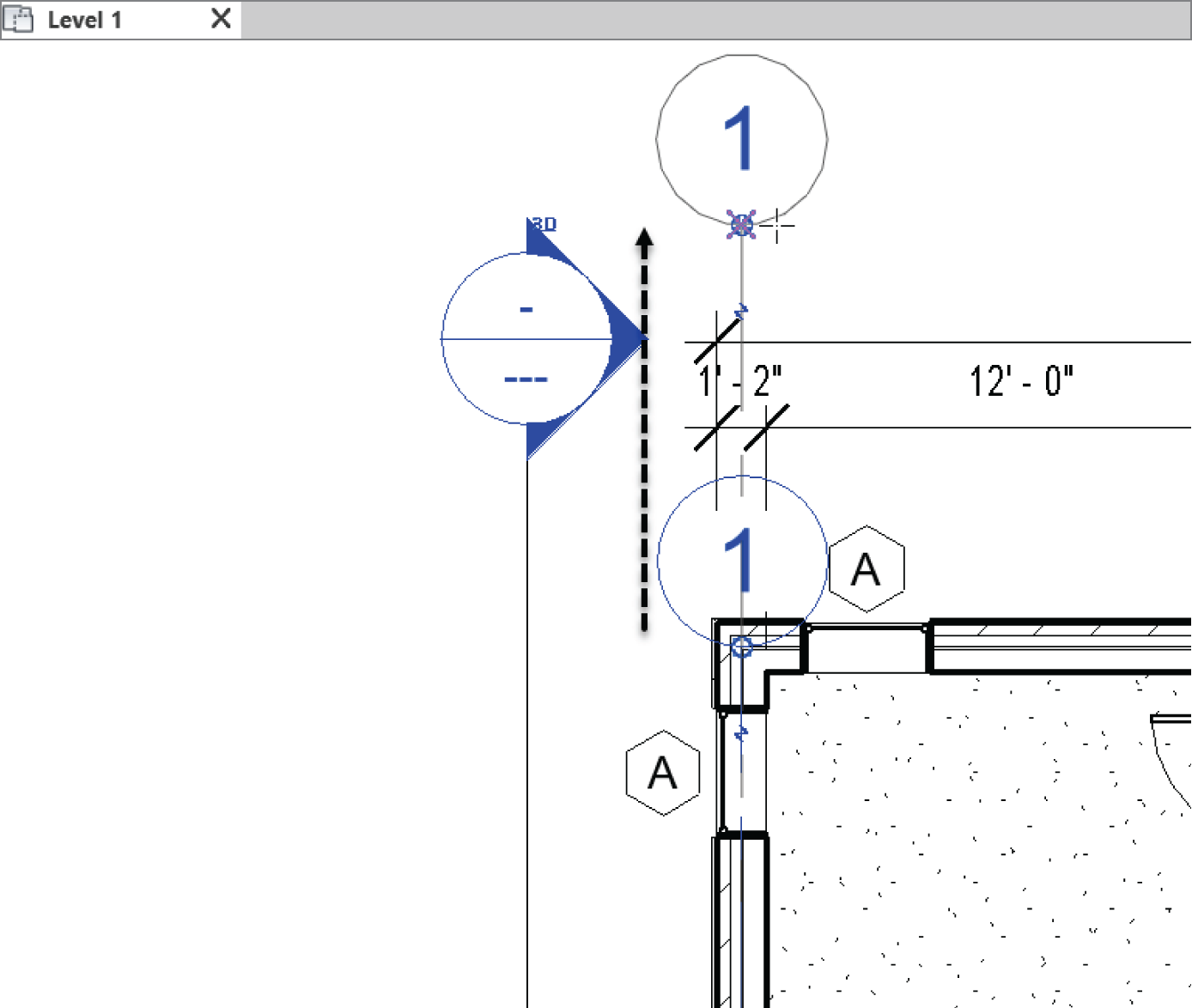
FIGURE 8.4 Dragging the column bubble up
- Select the grip and move the grid down about 4′ (102 mm), or so.
- Click the blue box to turn on the bubble. See Figure 8.5.
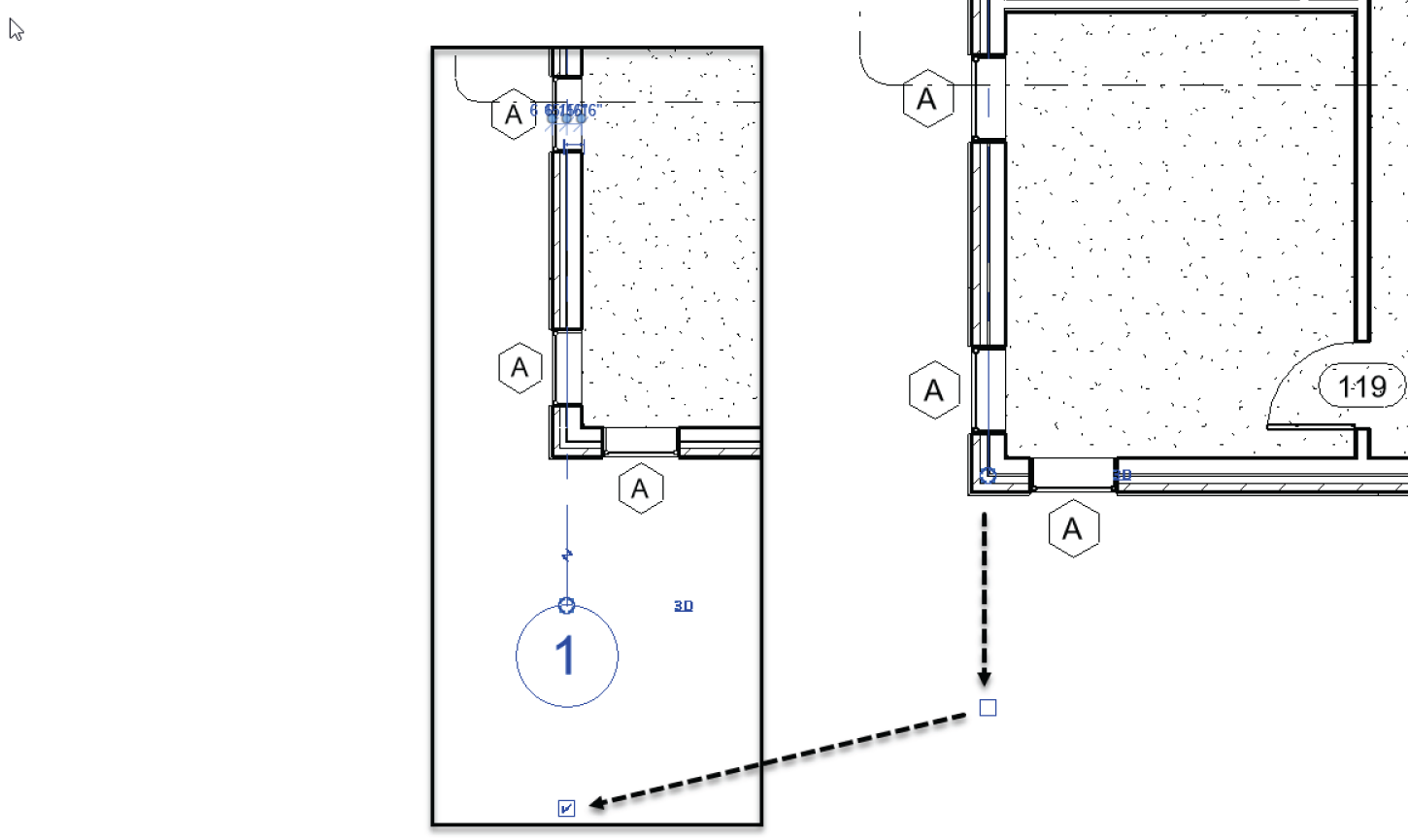
FIGURE 8.5 Adjusting the bottom of grid 1
Let's start adding more grid lines. This procedure will involve selecting column line 1 and copying it to the right using some walls as placement points.
- Select grid 1.
- Click the copy button, as shown in Figure 8.6.
- On the Options toolbar, click Constrain and Multiple, as illustrated in Figure 8.6.
- Select a point on grid 1 approximately where shown in Figure 8.6.
- Pick a point on the centerline of the wall (see Figure 8.6).
- Using the same technique in steps 1–5, add grids as shown in Figure 8.7.

FIGURE 8.6 Adding grid line 2 by using the copy function
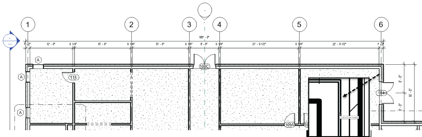
FIGURE 8.7 Adding more grids
Being able to pick lines is certainly an advantage, but you won't always be in a situation where you have geometry in place to do so. In the following procedure, you'll add grid 7 by picking two points:
- Right‐click on grid 6 and select Create Similar (see Figure 8.8).
- With the grid command running, we want to actually draw this one by clicking two points. Pick the point shown in Figure 8.9.

FIGURE 8.8 Right‐click on any object for which you'd like to create another instance.
- For the second point, move your cursor straight up until you see an alignment line as you come into alignment with the adjacent grid bubbles, and pick the second point (see Figure 8.9).
- Select grid 7 and drag the bottom down to align with the bubble on grid 6 on the south side of the building, and turn the bottom bubble on.
- Press Esc.
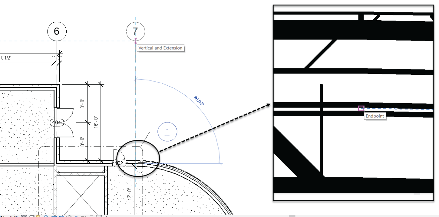
FIGURE 8.9 Draw the new grid by picking two points.
OK, great! Now, let's start adding our horizontal grids. We are going to do this in an incredibly similar fashion to how we did the vertical grids.
- Zoom in to the west side of the east building, as shown in Figure 8.10.
- Right‐click on grid 1 and select Create Similar.
- On the Draw panel, select the Pick Lines button, as shown in Figure 8.10.
- Pick the center of the north horizontal wall.
- As we have done before, select the grip at the end of the grid line, and drag the line to the left.
- Click the Show Bubble button to turn on the bubble.
- Rename the grip to A, as shown in Figure 8.11.
- Go to the other side of the building and drag the grid to the right to resemble Figure 8.12. Be sure it is stretched out far enough to clear the radial wall because we will be copying this grid down multiple times.
- OK! Now copy grid A to the center of the walls shown down to grid F. You can do it! See Figure 8.13.
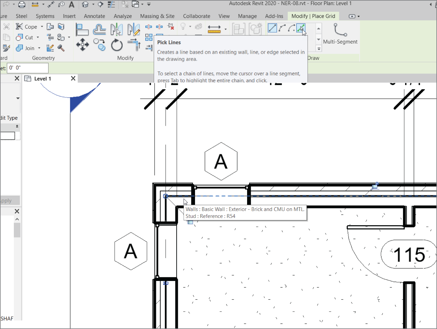
FIGURE 8.10 The first horizontal grid

FIGURE 8.11 Edit the grip and rename it to A.
Let's add three more grids and we're done! What we need to do here is add two 45° grid lines as well as a radial grid 6″ (152 mm) inside the face of the radial wall. Let's start with the radial grid line.
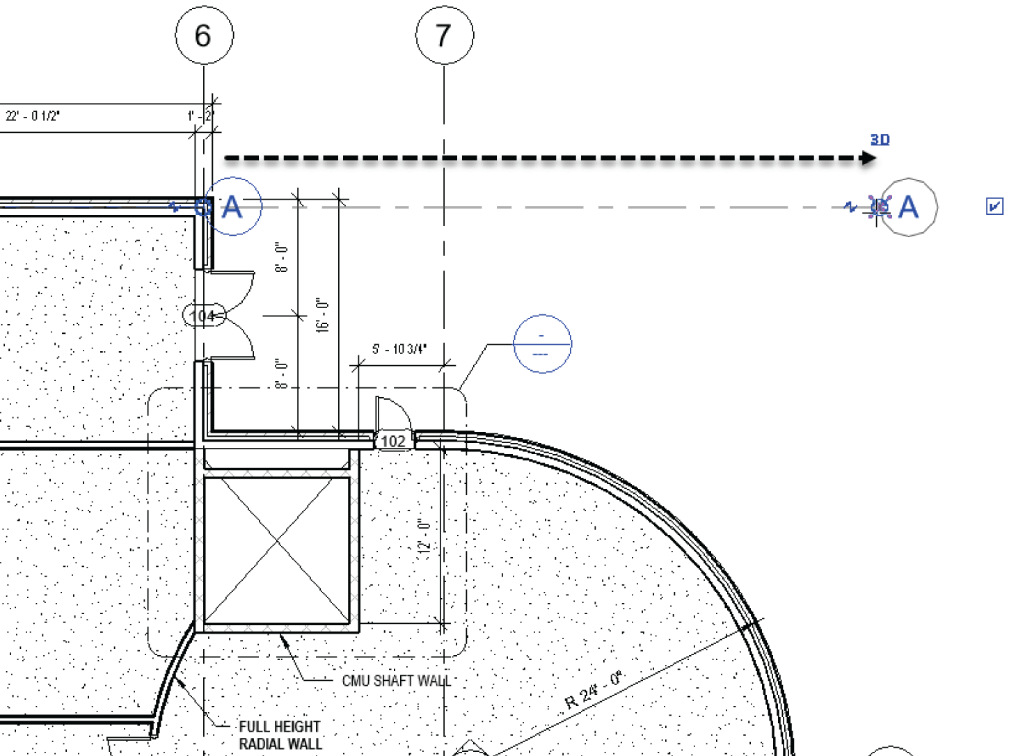
FIGURE 8.12 Completing gridline A
- Find any grid, select it, right‐click, and select Create Similar.
- On the Draw panel, select the Pick Lines button.
- In the Offset dialog, type 6″ (152 mm).
- Pick the inside face of the radial wall, as shown in Figure 8.14.
- Press Esc a couple times, select grid G, and drag the grips as shown in Figure 8.15. Turn on the bubble on both sides.
You need to add two more grids at 45° angles. This will be as easy as drawing lines. The objective here is to manipulate the grids to read the appropriate numbering:
- On the Architecture tab, click the Grid button if it's not selected already.
- Pick the center of the radial wall.
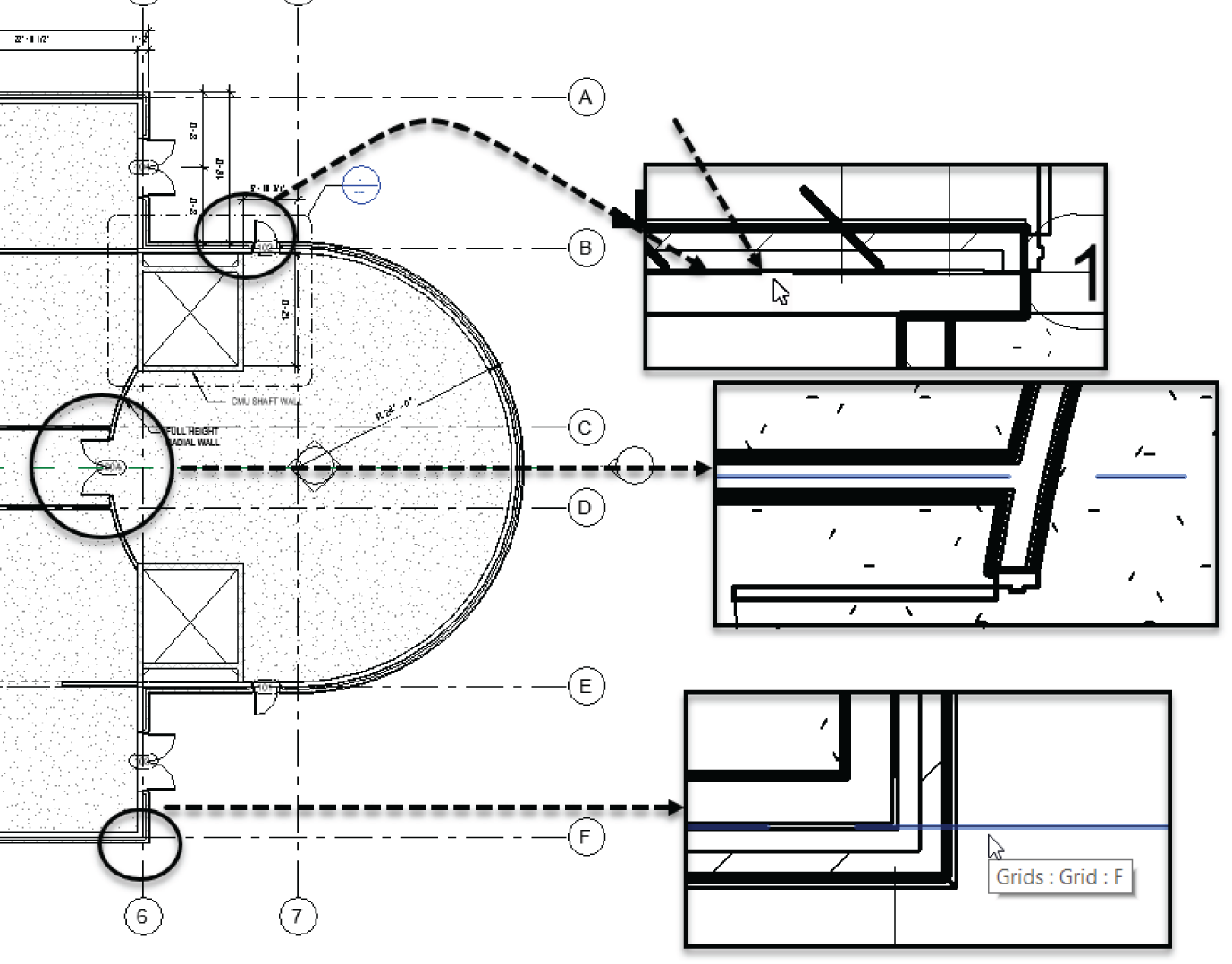
FIGURE 8.13 Completing gridline A through F

FIGURE 8.14 Adding a radial grid G
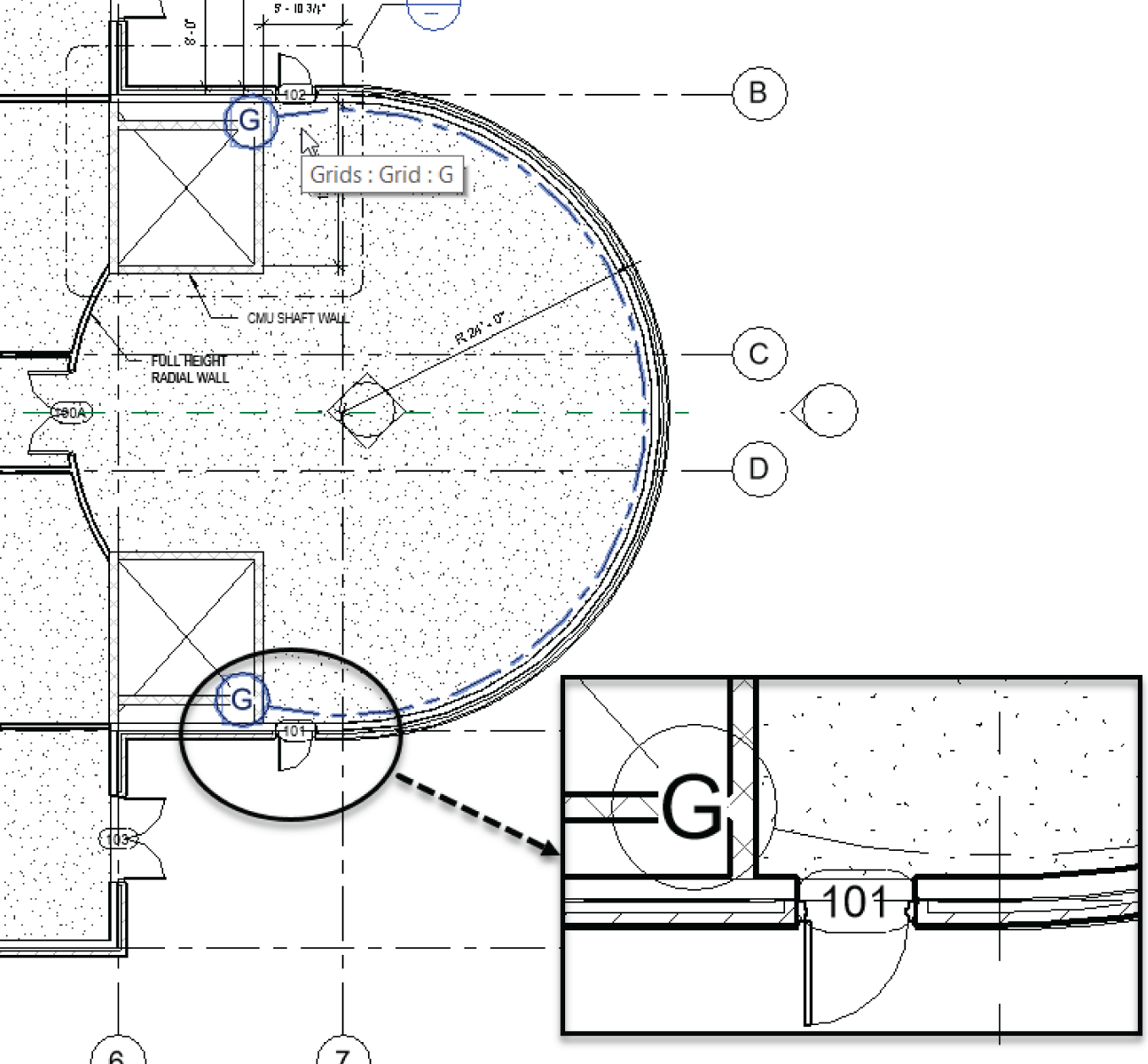
FIGURE 8.15 Completing radial grid G
- Draw the line at a 45° angle until you're beyond the radial wall, as shown in Figure 8.16 and Figure 8.17.
- Click in the bubble for the angled grid, and rename the grid line B.1. You can do this while placing grids. Click outside the grid number field to enter the change.
- Draw another grid line at a 45° angle in the opposite direction.
- Rename it to read D.9 (see Figure 8.17).
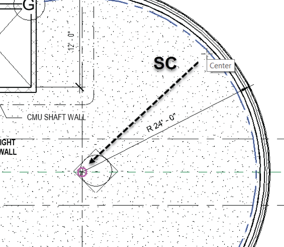
FIGURE 8.16 Hover over grid G and type SC (Snap Center) to find the center.
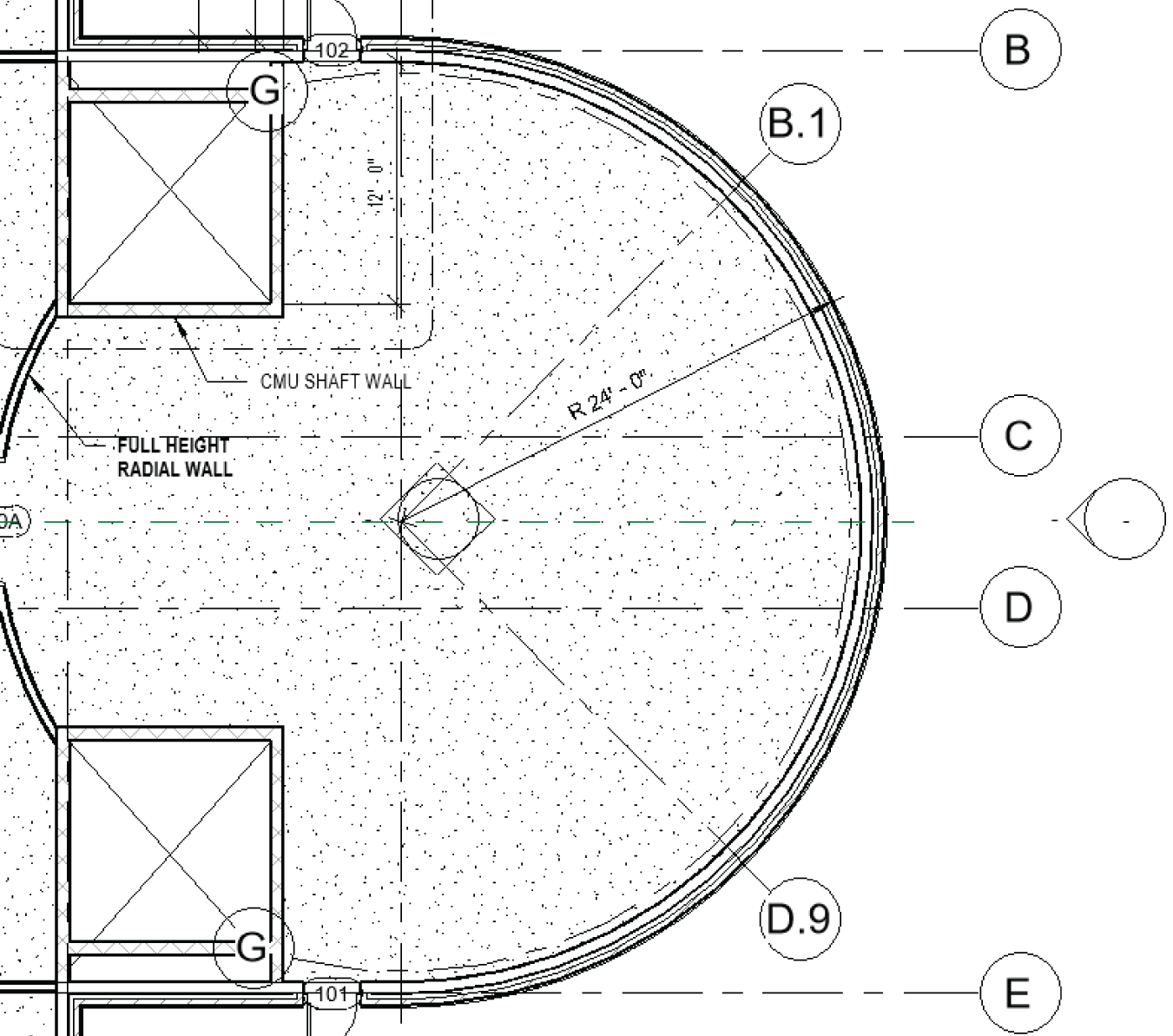
FIGURE 8.17 Grids B.1 and D.9 at 45° angles
Adding Elbows
As with levels, you can add a break in the line of the grid, allowing you to make adjustments as if the grid were an arm with an elbow. Follow along:
- Select grid C.
- Several blue grips appear. Pick the one that appears as a break line, as shown in Figure 8.18.

FIGURE 8.18 Clicking the Add Elbow grip after selecting the grid
- Picking this break line adds an elbow to your grid line, as shown in Figure 8.19.
- Adjust both C and D to look a little cleaner, as shown in Figure 8.20.
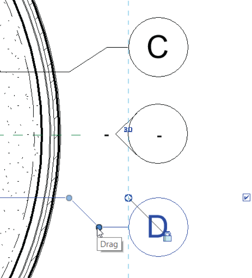
FIGURE 8.19 The cleaned‐up grid bubbles

FIGURE 8.20 The finished grids
Adding Structural Columns
The hard part is over. Determining where to put the columns is more difficult than physically placing them in the model. But of course there are rules to follow, as well as rules you need to bend in order to accomplish the results you want to see.
This next series of procedures includes adding structural components to the model and placing framing systems in areas where you as the architect would like to see exposed framing.
To add columns to the model, follow this procedure:
- In the Project Browser, go to the Level 1 floor plan.
- Zoom into the radial entry area in the east wing.
- On the Structure tab, choose Column ➣ Structural Column, as shown in Figure 8.21. This tool is also on the Architecture tab.
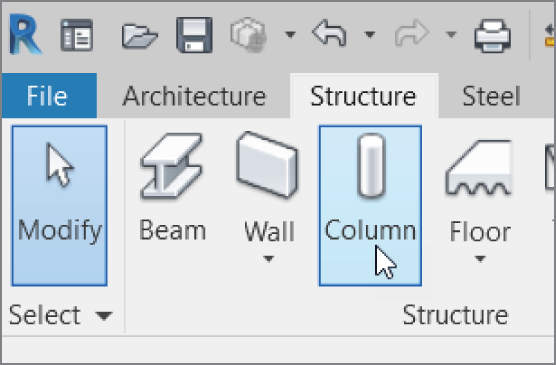
FIGURE 8.21 Column ➣ Structural Column on the Structure tab of the Ribbon
- Click the Load Family button, as shown in Figure 8.22.
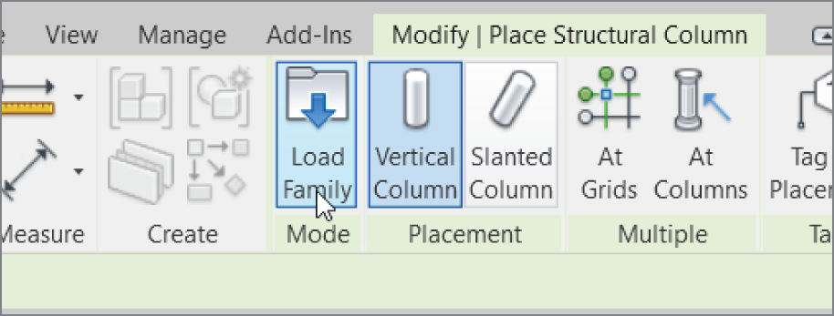
FIGURE 8.22 You can click the Load Family button to add additional columns to your project.
- Browse to US Imperial ➣ Structural Columns ➣ Steel (or Metric ➣ Structural ➣ Columns ➣ Steel).
- In the
Steelfolder, browse toHSS‐Hollow Structural Section‐Column.rfa(orM_HSS‐Hollow Structural Column.rfa). - Double‐click
HSS‐Hollow Structural Section‐Column.rfa(orM_HSS‐Hollow Structural Column.rfa). A dialog opens, enabling you to select the type, as shown in Figure 8.23. - Select the HSS6×6×5/8 (HSS152.4×152.4×12.7) column.
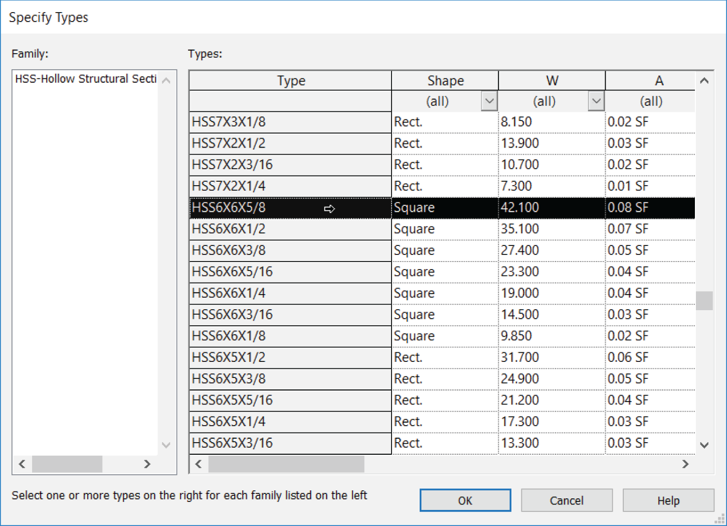
FIGURE 8.23 Select
HSS‐Hollow Structural Section‐Column.rfa, and choose the HSS6×6×5/8 (HSS152.4×152.4×12.7) type. - Click OK.
- On the Options bar, make sure Height is set to Roof, as shown in Figure 8.24.
- Place the column at grid intersection A‐1.
- Press Esc twice.

FIGURE 8.24 Changing Height to Roof and selecting grid intersection A‐1
- Choose Column ➣ Structural Column on the Structural tab. Once you do, make sure Height is still set to Roof.
- Select the At Grid button, as shown in Figure 8.25.
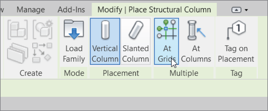
FIGURE 8.25 Select At Grids.
- Create a pick box (by picking and dragging your cursor) by picking a point at point 1 for the first point, and a point at point 2 for the second point (see Figure 8.26).

FIGURE 8.26 Picking a box around all of the grids
- Click the green Finish Edit Mode button, as shown in Figure 8.27.
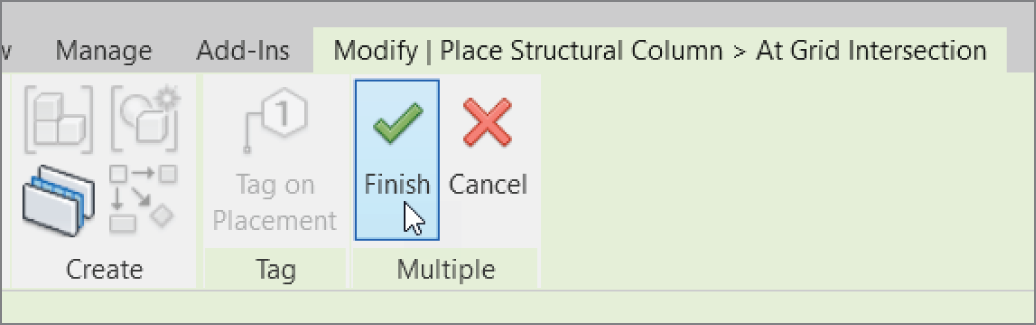
FIGURE 8.27 Click the green Finish Edit Mode button.
- Delete the three columns shown in Figure 8.28.

FIGURE 8.28 Cleaning up any errant columns
Now, quite a few columns are placed. You'll need to move some of them, including the four columns in the corridor intersection area. Revit will still locate each column at a grid intersection, but it will add the offset in the column's properties.
To move the columns and create a column offset, follow these steps:
- Zoom into the middle of the east wing at the corridor intersection.
- Select the two columns at the left of the corridor, as shown in Figure 8.29.
- Move the columns 4′–0″ (1200 mm) to the left (see Figure 8.29).
- Repeat the same procedure (only to the right) for the other two columns (see Figure 8.30).
- Save the model.
That's enough on columns for now. It's time to move on to adding some structural framing. You'll add framing primarily in the canopy areas surrounding the east entry of the east wing.
Using Structural Framing
Although you won't create much structural framing in Revit Architecture, you'll need to add framing in a few areas. Canopies with light structural framing are certainly one area that could call for the architect to wander over to the structural side of the fence.

FIGURE 8.29 Moving the columns to the left 4′–0″ (1200 mm)
To begin adding structural framing, follow along:
- In the Project Browser, go to the Level 2 floor plan.
- Zoom into the radial entry area.
- Select columns A‐7 and F‐7 (these are the columns outside the building).
- In the Properties dialog, set Top Level to Level 2. (This makes the columns disappear for a moment.)
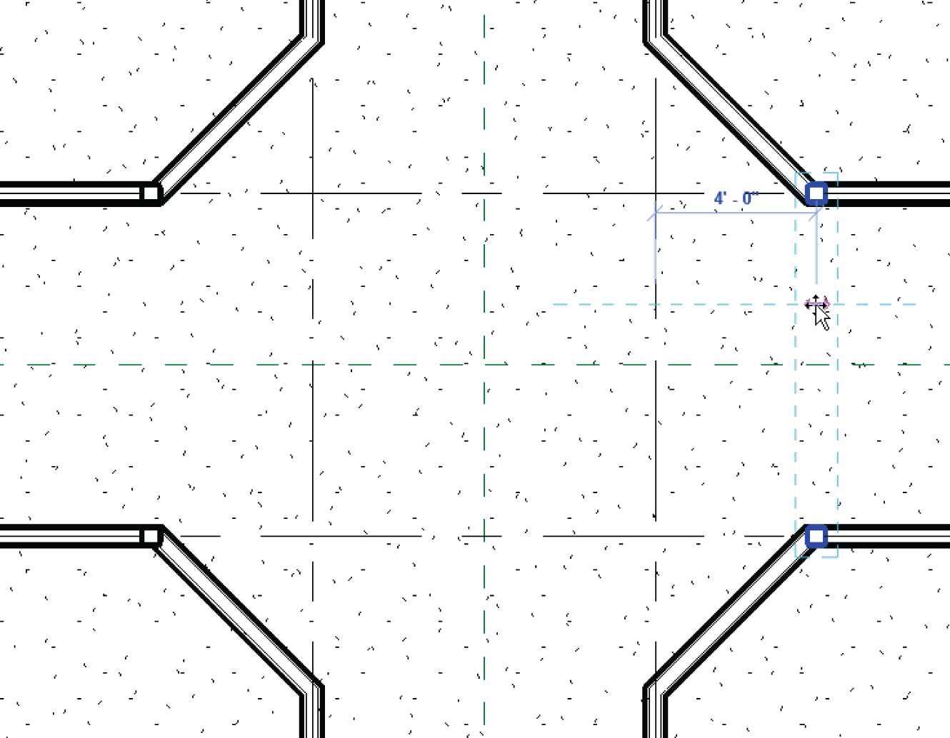
FIGURE 8.30 Adjustments such as moving a column will be necessary quite often.
- Press Esc.
- In the Properties dialog, scroll down to the View Range row and click the Edit button (see Figure 8.31).
- In the dialog that opens, in the Primary Range section, set Bottom Offset to ‐1′–0″(‐300 mm).
- For View Depth, set Level Offset to ‐1′–0″ (‐300 mm), as shown in Figure 8.31.
- Click OK. You can now see the column.

FIGURE 8.31 Setting the view range so you can see below the level
Next, you'll place the structural framing. Make sure you're zoomed into the northeast corner of the east wing. Here are the steps:
- On the Structure panel of the Structure tab, click the Beam button, as shown in Figure 8.32.

FIGURE 8.32 The Beam button on the Structure panel of the Structure tab
- Click the Load Family button.
- Browse to Structural ➣ Framing ➣ Steel.
- Select
HSS‐Hollow Structural Section.rfa(orM_HSS‐Hollow Structural Column.rfa). Click Open. - In the Specify Types dialog, select HSS6×6×5/8 (HSS152.4×152.4×12.7), and click OK.
- Pick the first point at column A‐6, which is buried in the corner of the wall.
- Pick the second point at exterior column A‐7, as shown in Figure 8.33.

FIGURE 8.33 Adding the beam requires picking two columns.
- With the Beam command still running, pick the exterior column (A‐7) and then column B‐7, as shown in Figure 8.34.
- Press Esc.

FIGURE 8.34 Adding the second beam
- Draw a beam 6″ (150 mm) off the finish face of the wall, starting at the top beam and ending on column line B, as shown in Figure 8.35. (This beam will later be supported by the framing within the building.)
- In the View Control bar, change Visual Style to Wireframe, as shown in Figure 8.36. This allows you to see the beam within the wall you're about to draw.
- Draw another beam from left to right, inside the wall, as shown in Figure 8.36.
- Save the model.
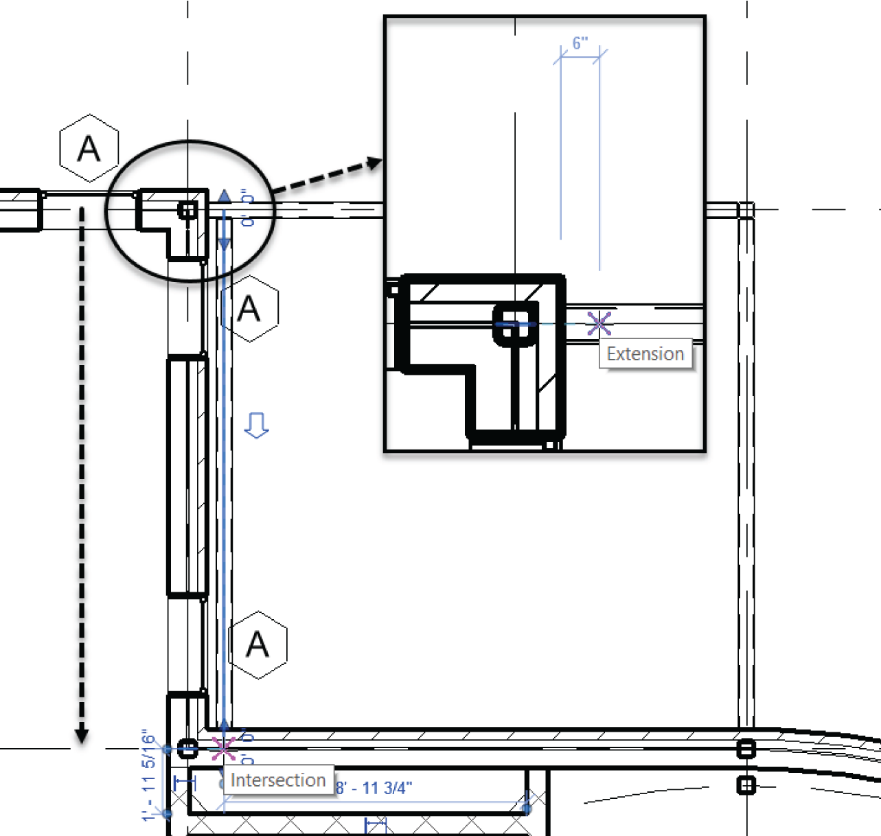
FIGURE 8.35 Adding a beam 6″ (150 mm) off the face of the wall to column line 2
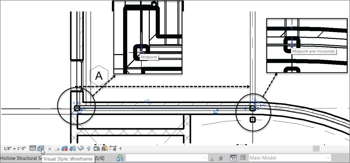
FIGURE 8.36 Completing the framing for the canopy
Now let's add some filler beams. In Revit Architecture, you can add a beam system that is controlled by a specified spacing. After the system is in place, you can control the properties for the duration of the project.
Adding a Beam System
Although adding beam systems in Revit is much more crucial for structure, it's useful for architecture as well. Having the ability to space a framing system equally can be quite advantageous.
To create a beam system, follow along with this procedure:
- On the Structure panel of the Structure tab, click the Beam System button, as shown in Figure 8.37.

FIGURE 8.37 The Beam System button
- Make sure the Automatic Beam System button is picked, as shown in Figure 8.38.
- Click the Tag On Placement button (see Figure 8.38).
- On the Options bar, make sure HSS6×6×5/8 (HSS152.4×152.4×12.7) is the Beam Type selection.
- Change Layout Rule to Maximum Spacing, as shown in Figure 8.38. Set the distance field to 4′–0″ (1200 mm).
- Change Tag Style to Framing.
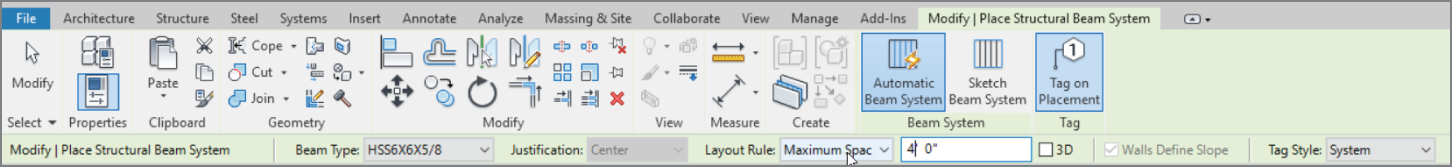
FIGURE 8.38 Setting the maximum spacing and the tag style on the Options bar
- Hover your cursor over the top, horizontal beam, as shown in Figure 8.39. Notice the green dashed lines; this is where your beams will be placed.

FIGURE 8.39 Getting ready to place the framing system
- When you see the green lines, pick the top beam, and your framing is placed (see Figure 8.40).
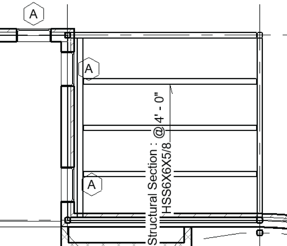
FIGURE 8.40 The framing of the canopy
- Press Esc a couple times, and pick a box around the framing you just added. Don't worry if you over‐selected some stuff.
- Click the Filter button, as shown in Figure 8.41.
- Click Check None.
- Select only the items checked in Figure 8.41.
- Click OK.
- Click the Mirror Pick Axis button, as shown in Figure 8.42 (or type MM, which is the keyboard shortcut for Mirror‐Pick Axis).
- Pick the center reference plane as shown in Figure 8.42, and your framing is now mirrored.
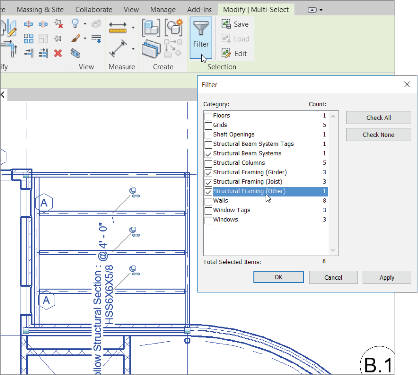
FIGURE 8.41 Selecting the framing you wish to mirror to the south side
By using the Beam System command, you can easily and quickly add multiple occurrences of framing members. In some cases, however, you need non‐uniform members on a different plane, such as lateral bracing.
Adding Bracing
It would be nice to add a rod to the top of this canopy at an angle. You can accomplish this by using the Brace command. To do so, you'll need to load the rod (considered a family in Revit) into the model.
To use the Brace command, first add the rod family to your model:
- Go to the Insert tab on the Ribbon.
- Click the Load Family button.

FIGURE 8.42 Picking the center reference plane to mirror your framing
- Browse to Structural ➣ Framing ➣ Steel, and open the file
Round Bars.rfa(orM_Round Bars.rfa). - Select RB 1 1/2.
- Go to the North elevation in the Project Browser. Notice that grid lines 1–7 are visible in this view—very useful!
- In the Properties panel for the North elevation, change Detail Level to Fine and Visual Style to Shaded.
- Zoom in on the east canopy.
- On the Structure panel of the Structure tab, click the Brace button, as shown in Figure 8.43.
- Revit displays a dialog asking you to specify a work plane. In the Name drop‐down list, select Grid : A, as shown in Figure 8.44, and then click OK.
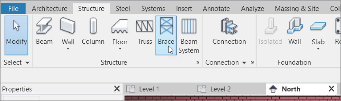
FIGURE 8.43 The Brace button on the Structure tab – Specify Grid A
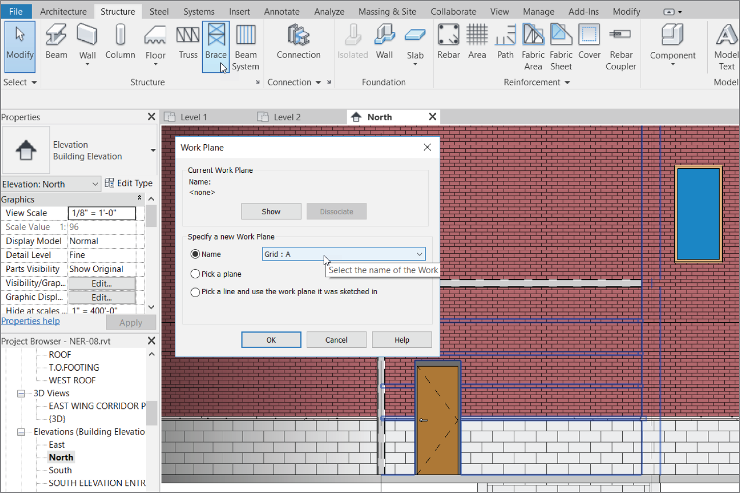
FIGURE 8.44 Selecting Grid : A
- Verify that Round Bar: 1‐1/2″ (M_Round Bar 38) is the current framing member in the Type Selector.
- Draw a diagonal bar, as shown in Figure 8.45. (I'll let you eyeball this one, or you can make the top offset a specific increment.)
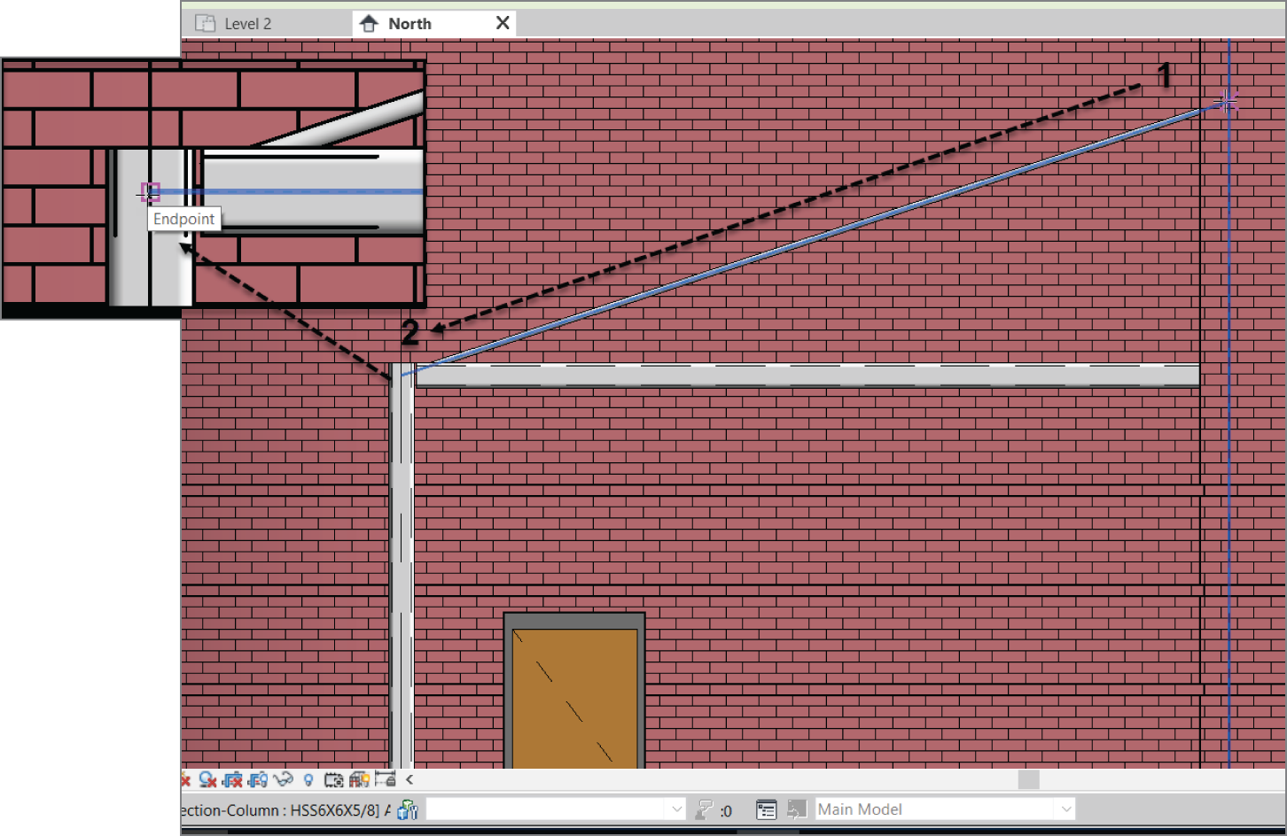
FIGURE 8.45 Adding the rod at an angle
- Go to the Level 2 floor plan.
- On the View tab, click the Elevation drop‐down arrow and select Framing Elevation, as shown in Figure 8.46.
- Hover your mouse over grid line 7. Notice once you come to within range with your cursor, the elevation marker shows up. This indicates that you are about to add an elevation, and that elevation will have its work plane set to grid 7.
- Once you see the elevation marker appear, pick the grid line (see Figure 8.46). Press Esc.
- Open the elevation by double‐clicking on the target in the elevation marker.
- Rename the elevation FRAMING AT NORTH EAST CANOPY.
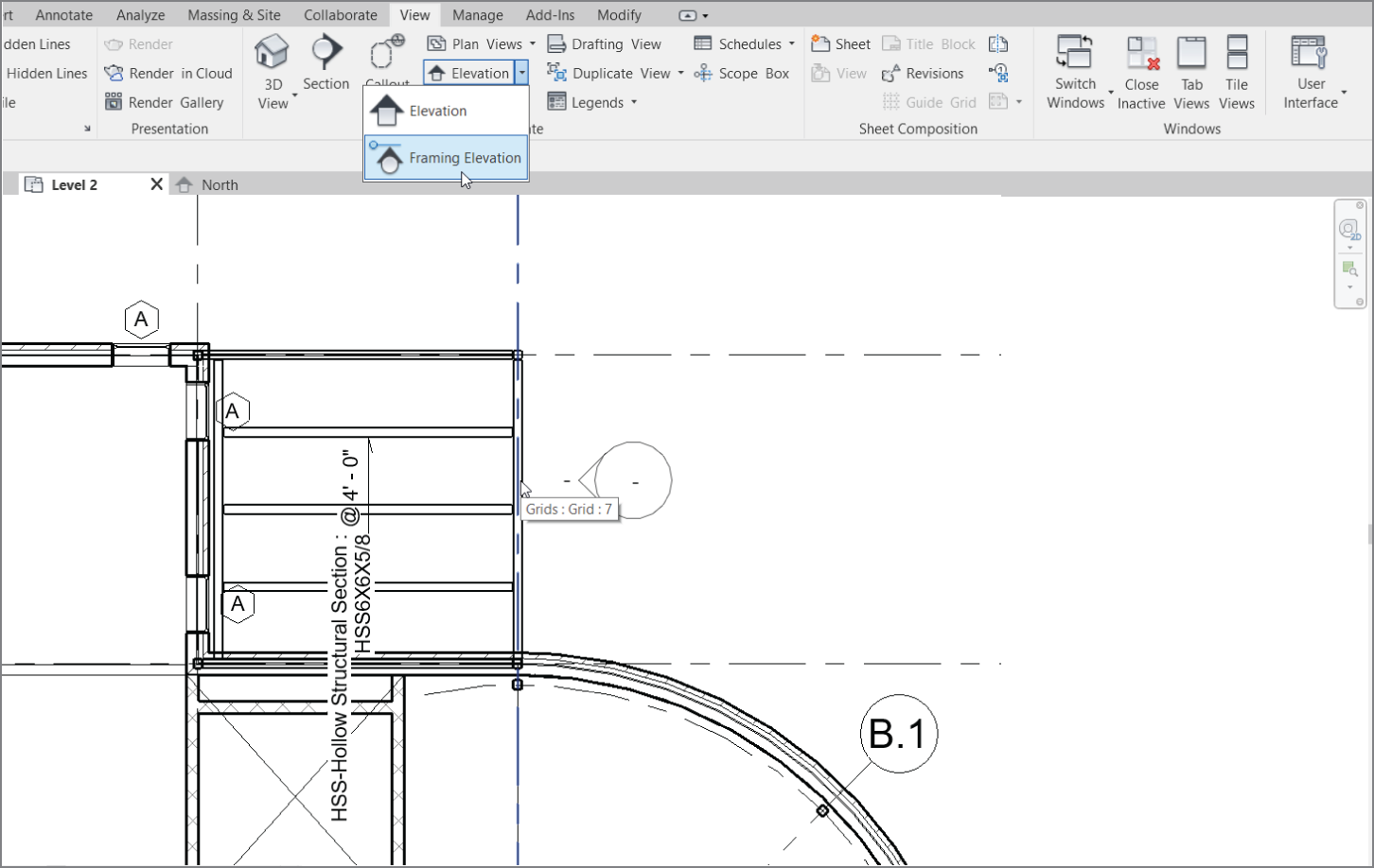
FIGURE 8.46 Adding a framing elevation
- Change Detail Level to Fine and Visual Style to Shaded.
- On the Structure panel of the Structure tab, click the Brace button.
- Draw a diagonal rod between the points shown in Figure 8.47, and press Esc.
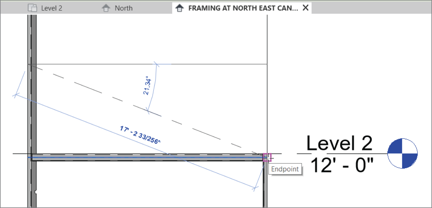
FIGURE 8.47 Finding the points along the column and beam to attach the rod
- Compare Figure 8.48 to your rods.
- Mirror the rods to the other canopy. You can open the East elevation to do so.
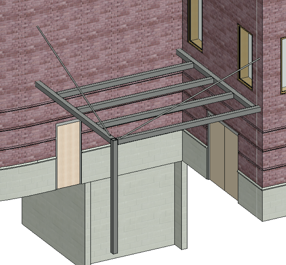
FIGURE 8.48 Isometric of the bracing
- Save the model.
That pretty much covers it for framing. The next section will bring you underground into the foundation. Although the structural engineer usually specifies the foundation system, architects must have access to foundation tools to place concrete foundation walls as well as to strip and isolate footings and piers. The next section addresses these topics.
Understanding Foundation Systems
The first question that arises while addressing structural foundations is, “What if the architect places a foundation in the model and then the structural engineer places one in their model?”
What will happen is the structural engineer will use a method called Copy/Monitor, whereby the engineer takes the architect's foundation and makes it their own. The engineer is then free to alter the foundation. We will cover this in a later chapter.
This section focuses on creating foundation walls. Although adding this type of wall is similar to adding architectural walls, there are a few things you need to be aware of.
For now, let's add a foundation and deal with coordination later. The task before you is to create a foundation wall constructed of 18″ (450 mm) of solid concrete. To proceed, follow these steps:
- Go to the Level 1 floor plan.
- Select one of your grids.
- On the View Control toolbar, click the button with the sunglasses, as shown in Figure 49. This is the Temporary Hide/Isolate function. This allows us to get items out of the way temporarily as we perform tasks that could be hampered by having these elements visible.
- Select Hide Category (see Figure 8.49).

FIGURE 8.49 Using the Temporary Hide/Isolate tool
- Click the Wall ➣ Wall: Structural button on the Structure tab.
- In the Type Selector, in the Properties dialog select Foundation ‐ 12" Concrete (Foundation – 305 mm Concrete), as shown in Figure 8.50.

FIGURE 8.50 Selecting a foundation wall
- Click the Edit Type button.
- Click the Duplicate button.
- Name the new wall Foundation ‐ 18″ Concrete (450 mm Concrete), as shown in Figure 8.51.
- Click the Edit button in the Structure row.
- In the Structure[1] row, change the Thickness to 1′‐6″ [457 mm].
- Click OK twice.
You're about to place a wall under this level. This view is currently set not to show anything below this level, forcing you to alter the view range.
To modify the view range, follow these steps:
- Press Esc twice, and then scroll down to View Range in the Properties dialog and click the Edit button.
- For Primary Range, set Bottom Offset to ‐1′–0″ (‐300 mm).
- For View Depth, set Level Offset to ‐1′–0″ (‐300 mm).

FIGURE 8.51 Building a structural foundation wall
- Click OK.
- Start the Structural Wall command again.
- On the Draw panel, click the Pick Lines icon.
- Foundation walls are placed top down, so Depth rather than Height appears on the Options bar. Make sure Depth is set to T.O. Footing and Justification is set to Wall Centerline.
- Pick the centerline of all of the exterior walls, as shown in Figure 8.52.
- Pick every exterior wall in all three sections of the model.
Your 3D model should look like Figure 8.53. Get into the habit of viewing the model in 3D—especially when you can't see exactly where the walls are being placed in the plan.
Now that the foundation walls are in place, let's think about what these walls are bearing on. Revit Architecture has tools to add footings to the bottom of the walls.
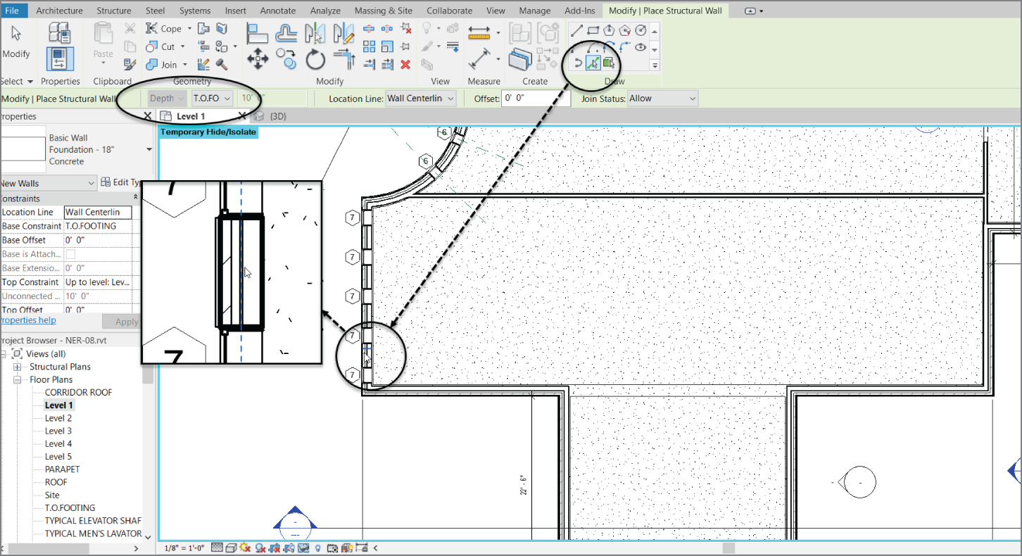
FIGURE 8.52 Picking the centerline of every exterior wall in the model. This includes the corridor and both wings.
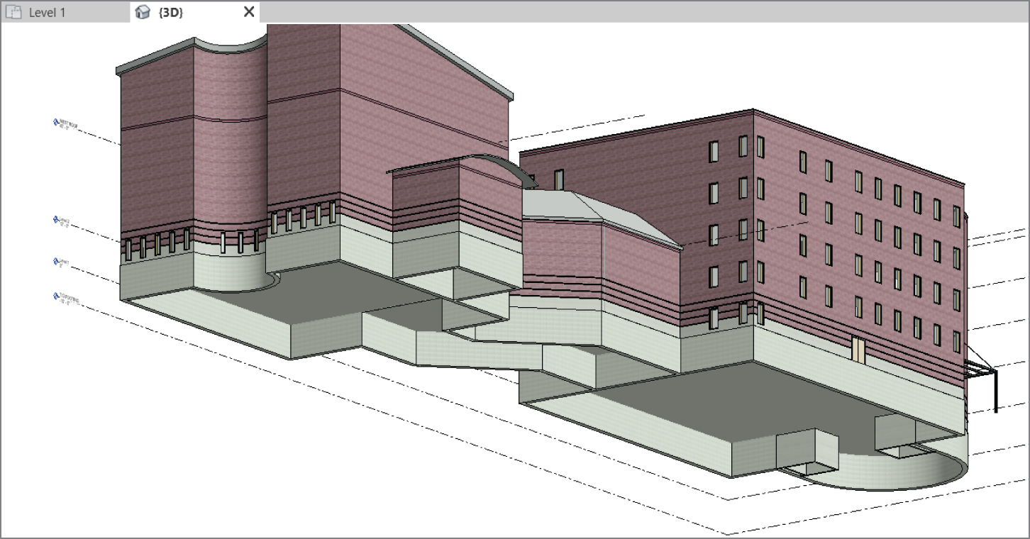
FIGURE 8.53 The foundation walls
Adding Structural Footings
If you're going as far as placing structural foundation walls, you might as well continue and place footings under them, right? Luckily, this isn't a difficult task.
Before you begin adding structural footings to the plan, you need to acknowledge that, by default, this view isn't set up to see objects that are physically below its level. To correct this, you must alter the view range of this specific plan. Follow these steps:
- In the Project Browser, go to the T.O. Footing plan.
- In the Properties dialog, go to the View Range row and click Edit.
- Set Primary Range Bottom to Unlimited.
- Set View Depth Level to Unlimited, as shown in Figure 8.54.
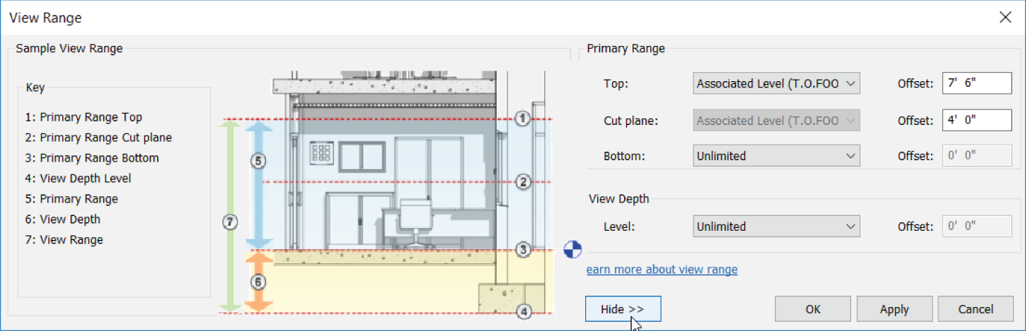
FIGURE 8.54 Again with the view range!
- Click OK.
- On the Foundation panel of the Structure tab, click the Wall button, as shown in Figure 8.55.

FIGURE 8.55 Adding a wall foundation
At the top of the Properties dialog, it says Bearing Footing ‐ 36″ × 12″ (900 mm × 300 mm). This is a little big for your purposes, so let's make a new footing:
- In the Properties dialog, click the Edit Type button.
- Click Duplicate.
- Call the new footing element Bearing Footing ‐ 30″ × 12″ (Bearing Footing ‐ 750 mm × 300 mm).
- Click OK.
- Change the Width setting to 2′–6″ (750 mm), as shown in Figure 8.56.

FIGURE 8.56 Changing the width
- Click OK again to get back to the model.
- Start picking walls. This footing will be centered under each wall you pick. Ignore the elevator shaft walls.
- When you've finished picking the walls, go to a 3D view to make sure all the foundations are covered, as shown in Figure 8.57.
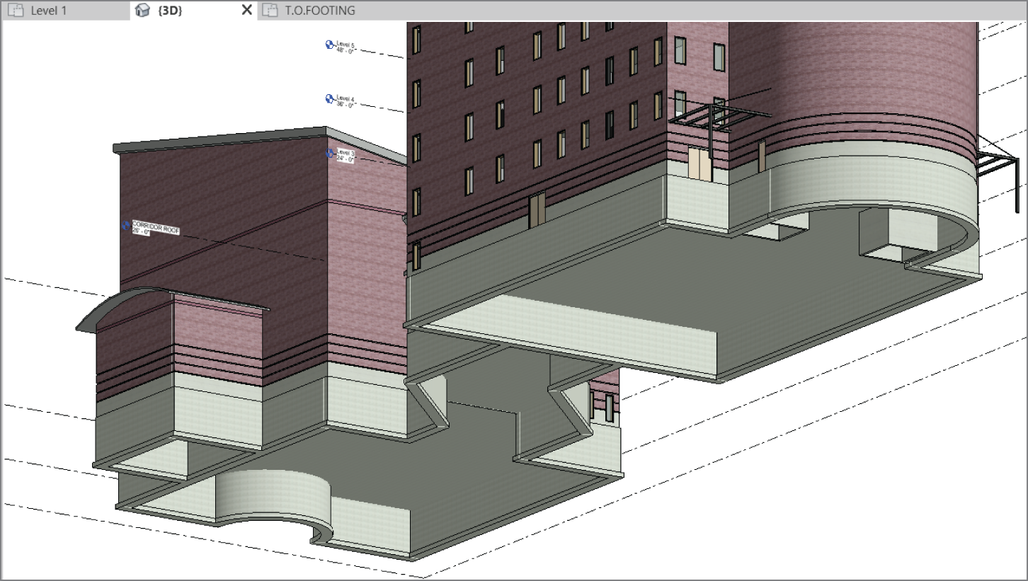
FIGURE 8.57 Doing a 3D investigation to see whether the footings are all in place
When all the footings are in place, you can see that you need to focus on the elevator shafts. Because an entire foundation mat is required under the elevators, you can use a structural slab.
Structural Slabs
Structural slabs are basically thick floors. The one you're about to use is a solid concrete floor 12″ (300 mm) thick. Of course, Revit doesn't have something this thick built in the library, so you'll take this opportunity to make one. Here are the steps:
- Go to the T.O. Footing floor plan.
- Zoom into the elevator area.
- On the Foundation panel of the Structure tab, choose Slab ➣ Structural Foundation: Slab, as shown in Figure 8.58.

FIGURE 8.58 Choosing Structural Foundation: Slab
- In the Properties panel, click Edit Type.
- Click Duplicate.
- Call the new slab 12″ Elevator Slab (300 mm Elevator Slab).
- Click OK.
- Click the Edit button in the Structure row.
- In the Layers field, change Thickness to 1′–0″ (300 mm), as shown in Figure 8.59.

FIGURE 8.59 Changing the structure thickness
- Click OK twice to get back to the model.
- On the Draw panel, verify that the Pick Walls button is selected.
- On the Options bar, set Offset to 6″ (152 mm).
- Pick the three elevator shaft walls, as shown in Figure 8.60.
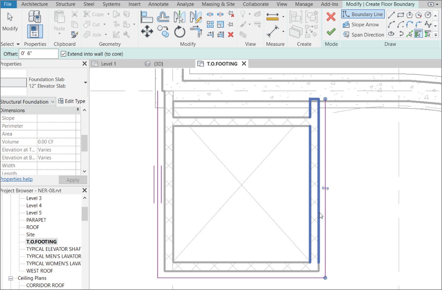
FIGURE 8.60 When picking the elevator shaft walls, be sure to include the 6″ (152 mm) offset.
- Set Offset back to 0.
- Select the Pick Lines button. Verify that the offset is 0.
- Pick the inside of the exterior foundation wall.
Now that the perimeter is set, it's time to trim the edges to make sure you have a continuous, closed loop:
- On the Modify panel, click the Trim/Extend To Corner button.
- Trim any overlapping corners, as shown in Figure 8.61.
- On the Floor panel to the right of the Create Floor Boundary tab, click Finish Edit Mode.
- Repeat the process for the south elevator.
- Go to a 3D view. Your finished elevators should look like Figure 8.62.

FIGURE 8.61 Trimming all the corners
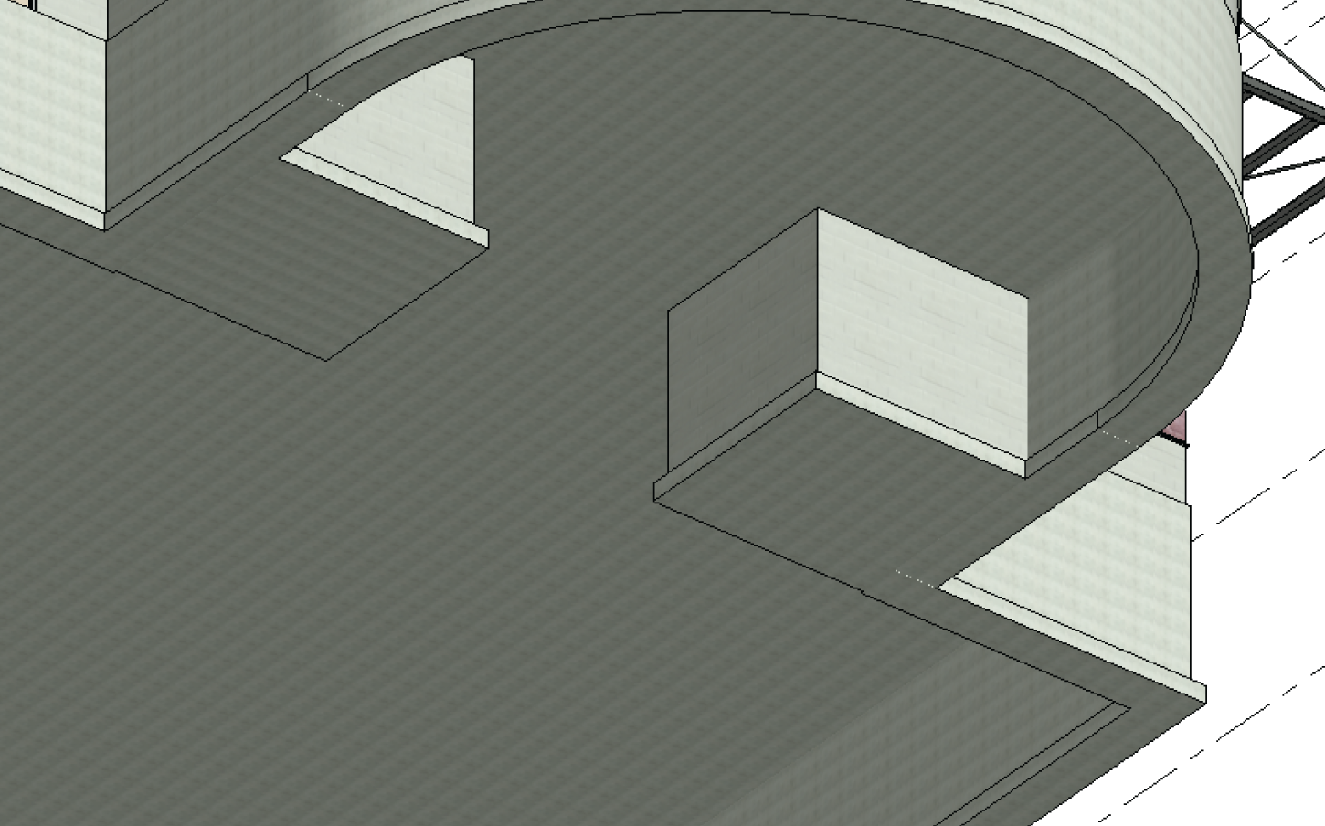
FIGURE 8.62 The finished elevator pads
With the footings mostly in place, you can think about placing piers and spread footings in the foundation. Luckily, as you're soon to discover, you already know how to do this.
Piers and Spread Footings
Piers and pilasters, simply put, are concrete columns. This is how Revit sees these items, and the following is the easiest placement method. A nice thing about this technique is that the grids are in place as well as the steel columns that bear on them. The only real trick is deciding which plan to put them in.
The objective of the next procedure is to add pilasters to support the columns bearing on them. Follow these steps:
- Return to the T.O. Footing plan.
- On the Structure panel of the Structure tab, click the Column button.
- On the Modify/Place Structural Column tab, click the Load Family button, as shown at the top of Figure 8.63.

FIGURE 8.63 Starting to place piers
- Browse to Structural ➣ Columns ➣ Concrete.
- Pick the file called
Concrete‐Rectangular‐Column.rfa(M_Concrete‐Rectangular‐Column.rfa). - Click Open.
- In the Type Selector, select the 12 × 18 (305 × 457 mm) column. Verify that Height is set to Level 1.
- Click Edit Type.
- Click Duplicate.
- Rename it to 30 × 30 (762 × 762), as shown in Figure 8.64.
- Change the dimensions b and h to 2′‐6″.[762 mm].
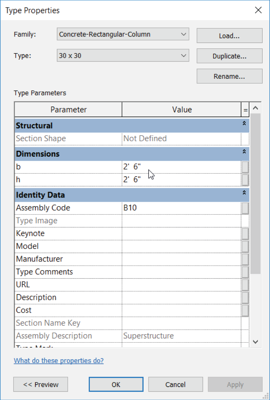
FIGURE 8.64 Building the pier
- Click OK.
- Click At Grids, as shown in Figure 8.65.
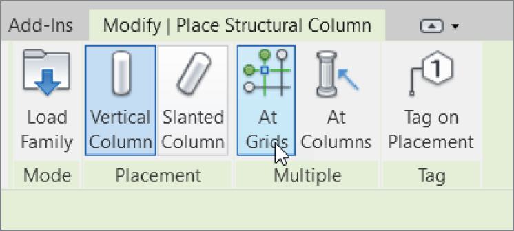
FIGURE 8.65 At Grids—what a timesaver!
- Pick a box around all of the grids, as shown in Figure 8.66.

FIGURE 8.66 Selecting the grids to place your columns
- Click the Finish button (the green check mark).
- Go to Level 1.
- Click the Temporary Hide/Isolate button and choose Reset Temporary Hide/Isolate, as shown in Figure 8.67.

FIGURE 8.67 Choosing Reset Temporary Hide/Isolate
- Move the piers under the columns in the corridor 4′‐0″ (1219 mm) that you moved earlier.
- Delete the extra piers in the radial entry area where there are no columns. See Figure 8.68.

FIGURE 8.68 Making the necessary adjustments
Now you'll add the spread (Isolated) footings under the piers. This process is almost identical to the previous one:
- Go back to the T.O. Footing floor plan.
- On the Foundation panel of the Structure tab, select the Isolated Foundation button.
- No structural foundations are loaded into the project, so click Yes.
- Browse to Structural ➣ Foundations.
- Select the file called
Footing‐Rectangular.rfa(M_Footing‐Rectangular.rfa). - Click Open.
- In the Properties dialog, click the Edit Type button.
- Click Duplicate.
- Call the new footing 42″ × 42″ × 12″ (1067 mm × 1067 mm × 300 mm).
- Click OK.
- Change Width to 42″ (900 mm).
- Change Length to 42″ (900 mm).
- Change Thickness to 12″ (300 mm).
- Click OK.
- Add these footings to each pier. The At Columns option on the Multiple panel works like At Grids and will speed up your work.
Your foundation plan should resemble Figure 8.69.
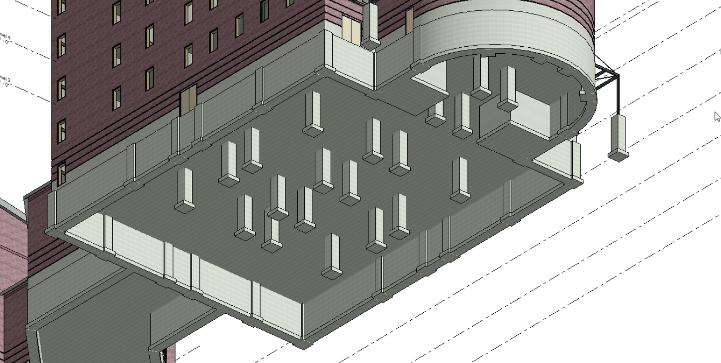
FIGURE 8.69 The completed foundation
Having a foundation in place in an architectural plan can be both good and bad. It can be bad because structural items begin appearing in places you may not want to see them. The last procedure of the chapter involves isolating the structure from the architecture.
Using Structural Views
By creating a structural view, you essentially duplicate an architectural view and hide the nonessential items in that view. Sound easy? That's because it is! But before you get started, you're going to remove some structural views that Revit provided for you.
To create structural views, follow these steps:
- In the Project Browser, find the Structural Plans category.
- Select all the structural plans in that category, right‐click, and select Delete to delete the plans.
Continue as follows:
- In the Project Browser, go to Floor Plans, right‐click T.O. Footing, and select Duplicate View ➣ Duplicate With Detailing, as shown in Figure 8.70. The new view opens.
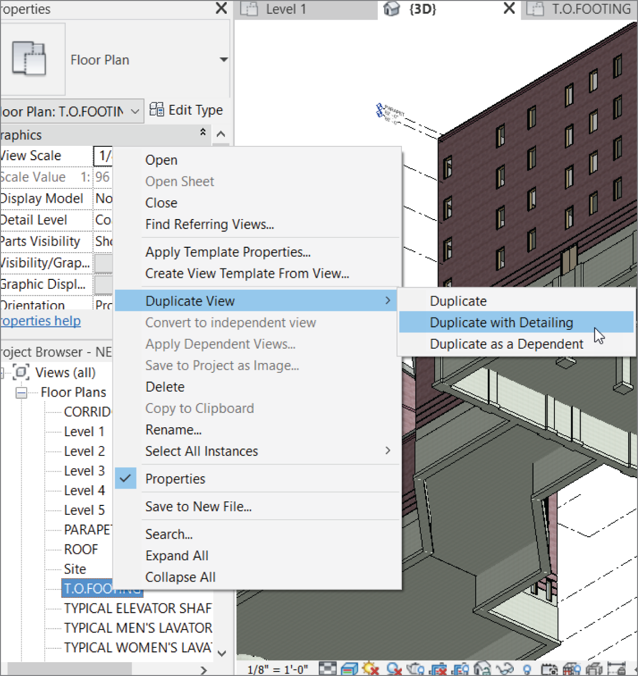
FIGURE 8.70 Selecting Duplicate View ➣ Duplicate With Detailing
- Rename the view called T.O. Footing Copy 1 to T.O. Footing Structural Plan.
- In the Discipline category of the View Properties, select Structural from the list, as shown in Figure 8.71. The sections disappear.
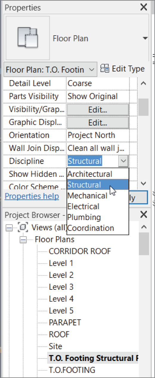
FIGURE 8.71 Changing Discipline to Structural
- In the Project Browser, right‐click Views (All), as shown in Figure 8.72.
- Select Browser Organization, as shown in Figure 8.72, to open the Browser Organization dialog.
- Select Discipline, as shown in Figure 8.73, and then click OK.
Now the Project Browser is broken into categories. This will be helpful for large projects with a mix of structure and architecture.
This is getting easy! Let's make the Level 1 architectural plan truly architectural, as follows:

FIGURE 8.72 Right‐clicking in the Project Browser

FIGURE 8.73 Selecting Discipline
- Open the Level 1 floor plan (Architectural).
- Scroll down to View Range.
- Click the Edit button in the View Range row.
- Change both the Bottom and View Depth offsets to 0.
- Click OK.
The foundation information is no longer displayed in the Level 1 floor plan.
Although the last part of this chapter was short, it's a nice look into the Project Browser, and it shows how you can begin to get organized. If you would like more practice, go into the Project Browser on your own and organize it the way you'd like.
Are You Experienced?
Now you can…
- place a structural grid in your model by using the architectural walls as a reference
- add additional grids at a radius or by sketch where needed
- add columns to the grid lines
- add columns at an offset, keeping the relationship to the grid intersection intact
- add structural beams to the model
- add structural beam systems, which can follow centering rules or equal‐distance spacing
- use the Brace command to create brace framing to be used for both architectural appointments and structural bracing
- create entire foundation systems complete with foundation walls, piers, and spread footings
- organize the Project Browser to show your model broken into disciplines
- change a view's discipline to Structural