CHAPTER 17
Rendering and Presentation
Well, here we are—the chapter you've probably been chomping at the bit to get into—and for good reason. The output that you create from this chapter will make your bosses and, better yet, your clients get behind your presentations. As I always say, none of this software is any good if you can't capture the work to begin with. That being said, in this chapter we'll focus on creating renderings, adding animations, and providing solar studies based on a project's geographical location.
This chapter covers the following topics:
- Creating an interior rendering
- Creating walkthroughs
- Creating a solar study
Creating an Interior Rendering
The first item we need to tackle is how to go about creating an interior rendering with no natural lighting. Trying to address the subject of rendering as a whole would convolute the matter. The thing is, when you create a rendering, lighting obviously plays a major role. Day lighting and artificial lighting are two completely different beasts—one will influence the effect of the other. For example, if you're rendering an exterior scene, there are bound to be windows. If this rendering appears at night or at dusk, the interior lights will be turned on.
The objective of the first section of this chapter is to create a rendering from the interior of a building but relying on daylighting to illuminate the scene.
To begin, open the file on which you ’ve been following along. If you didn’ t complete the previous chapter, go to the book’s web page at www.wiley.com/go/revit2020ner.
The goal of this procedure is to create a camera view that you can use for your first rendering. You'll then adjust the view controls and look at the sunlight effects. Follow along:
- In the Project Browser, open the Level 1 floor plan.
- Zoom in on the corridor area in the middle of the building.
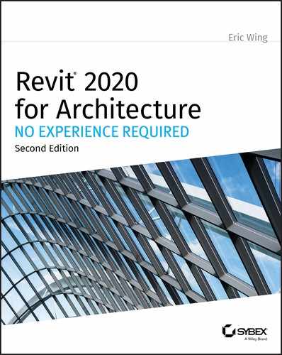
- Add some curtain walls to the corridors, as shown in Figure 17.1. (Come on, I know you can do it.) These are Level 1 to Level 3 with a ‐6″ (‐150 mm) offset from Level 3. You can use Curtain Wall Storefront.
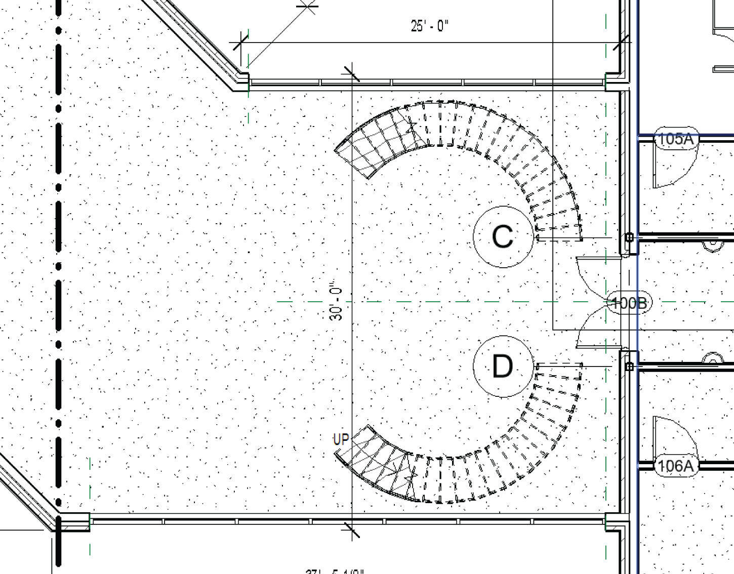
FIGURE 17.1 Add the curtain walls and create the camera view.
- On the View tab, select 3D View ➣ Camera, as shown in Figure 17.2.
- Click the point labeled 1 first, then the point labeled 2, as shown in Figure 17.2.
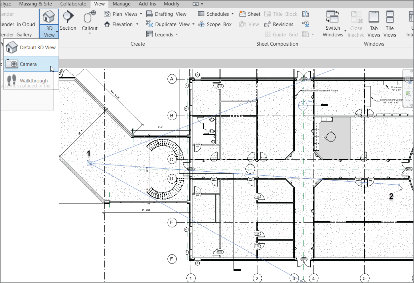
FIGURE 17.2 Adding the perspective view
- When the view opens, rename it Rendering View Corridor.
- Open the Rendering View Corridor view (it should open automatically).
- Select the crop region and widen the view, as shown in Figure 17.3.
- On the View Control bar, set Detail Level to Fine.
- Change Visual Style to Realistic.
- In the Properties dialog, click the Edit button in the Graphic Display Options row (see Figure 17.4).
- In the Graphic Display Options dialog, click into the Photographic Exposure section, and click the Enable Photographic Exposure check box.
- For Shadows, click Cast Shadows and Show Ambient Shadows.
- In the Lighting section, turn the Sun up to 100%.
FIGURE 17.3 Selecting Graphic Display Options and changing the crop region
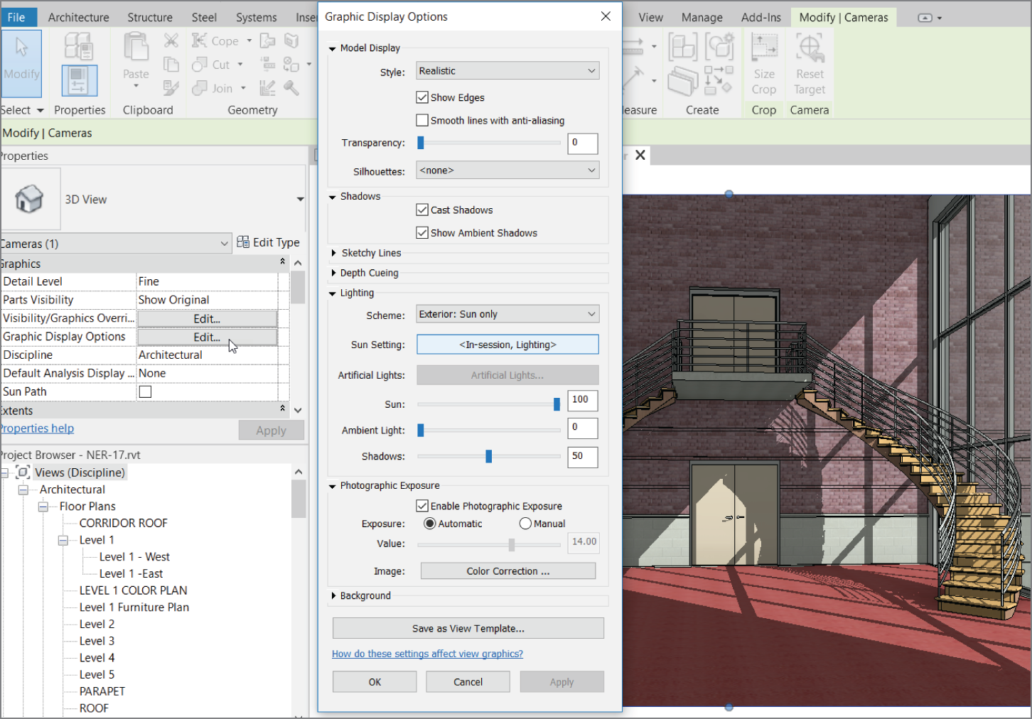
FIGURE 17.4 Brightening up the view
- Click OK.
- Click the Show Rendering Dialog button on the View Control bar, as shown in Figure 17.5.
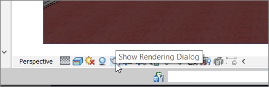
FIGURE 17.5 The Show Render Dialog button
In the Rendering dialog, you'll see quite a few choices. They vary depending on the scene you're trying to capture. The next procedure will move through the Rendering dialog from top to bottom.
At the top of the Rendering dialog is a Render button. This is the last button you'll click—it starts the rendering process. For the rest, follow these steps:
- For Quality, set Setting to Draft.
- For Output Settings, set Resolution to Printer and 150 dpi.
- In the Lighting category, set Scheme to Interior: Sun and Artificial.
- In the Background category, set Style to Sky: Very Cloudy (see Figure 17.6).
- Click the Render button. After the scene is rendered, it should appear similar to Figure 17.7.
- Click the Adjust exposure button in the image section.
- Change the settings to your liking.

FIGURE 17.6 The Rendering dialog
So you waited half your day for this rendering to complete. If you're like me, you carefully move your mouse around, wondering how long it will be before something happens and you lose your rendering.

FIGURE 17.7 The 150 dpi rendering
The next procedure will look at how to save the rendering to the model and also how to export the rendering to an image. Follow these steps:
- In the Rendering dialog, click the Save To Project button, as shown in Figure 17.8.
- Call the new rendering view Rendering at Corridor; then click OK.
- Click the Export button, and you can save the image as a JPEG or a TIFF.
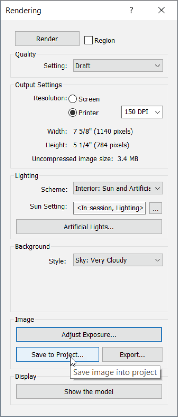
FIGURE 17.8 Saving the rendering to the project
- Save the file somewhere you can retrieve it. You can choose whichever file format you prefer.
- At the bottom of the Rendering dialog, in the Display section, click Show The Model. The rendering reverts to the original graphic style.
- Click the Show The Rendering button. The rendering reappears.
The ability to jump back and forth from the model to the rendering is a nice feature, but it's short‐lived. After you close this project, the rendering is no longer available. Don't close this project until you've finished saving the view to the model and exporting it (if you wish to do so).
Creating Lighting Groups
All too often, you render scenes with no real consideration for the lighting that has been added to the model. Because you lean heavily on Revit to produce accurate scenarios to present to clients, you should spend some time thinking through your lighting before you create a rendering.
In this procedure, you'll create a lighting group, then render an entirely indoor scene with no natural light. Follow along:
- Go to the Level 1 floor plan.
- Zoom in on the corridor area, as shown in Figure 17.9.
- Select one of the wall sconces.
- In the Type Properties dialog, click Edit Type.
- Scroll down to Light Loss Factor and click the button that says “1.” See Figure 17.9.

FIGURE 17.9 Adjusting the lighting levels
- With the light still selected, on the Options bar, click the Light Group menu, and select Edit/New (see Figure 17.10).
- In the Artificial Lights ‐ Level 1 dialog, click the New button in the Group Options area.
- Call the new group Lighting Corridor, as shown in Figure 17.10, and click OK.
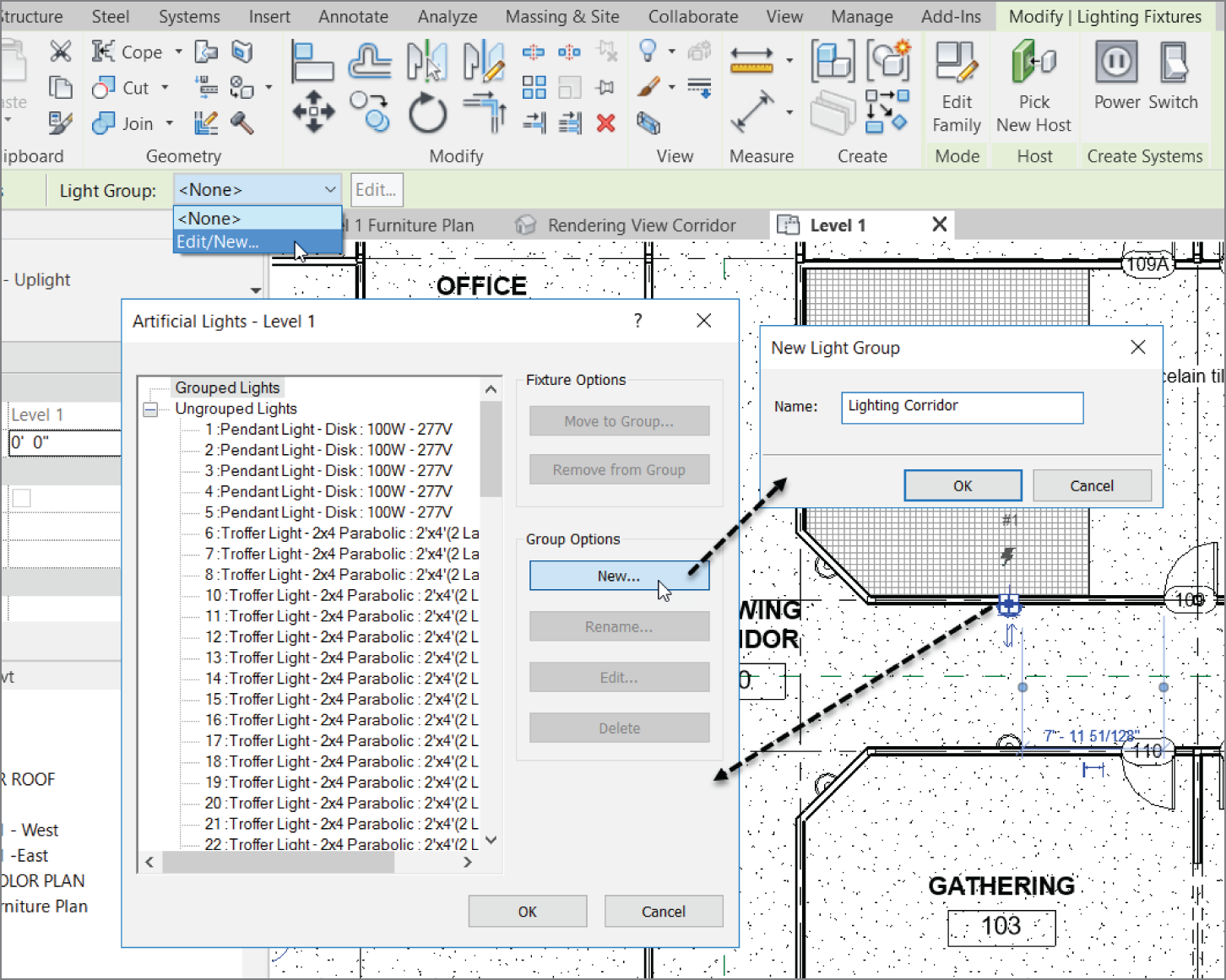
FIGURE 17.10 Creating a new group and adding the proper lights
- Scroll down to the bottom of the list and locate the lights Sconce Light ‐ Uplight: 100W ‐ 277V. Select all of them (see Figure 17.11).
- Click the Move To Group button under Fixture Options.
- Choose the Lighting Corridor group in the Light Groups dialog and click OK.
- Click OK to close the dialog.

FIGURE 17.11 Creating another perspective
- Create a perspective view down the corridor, as shown in Figure 17.12.
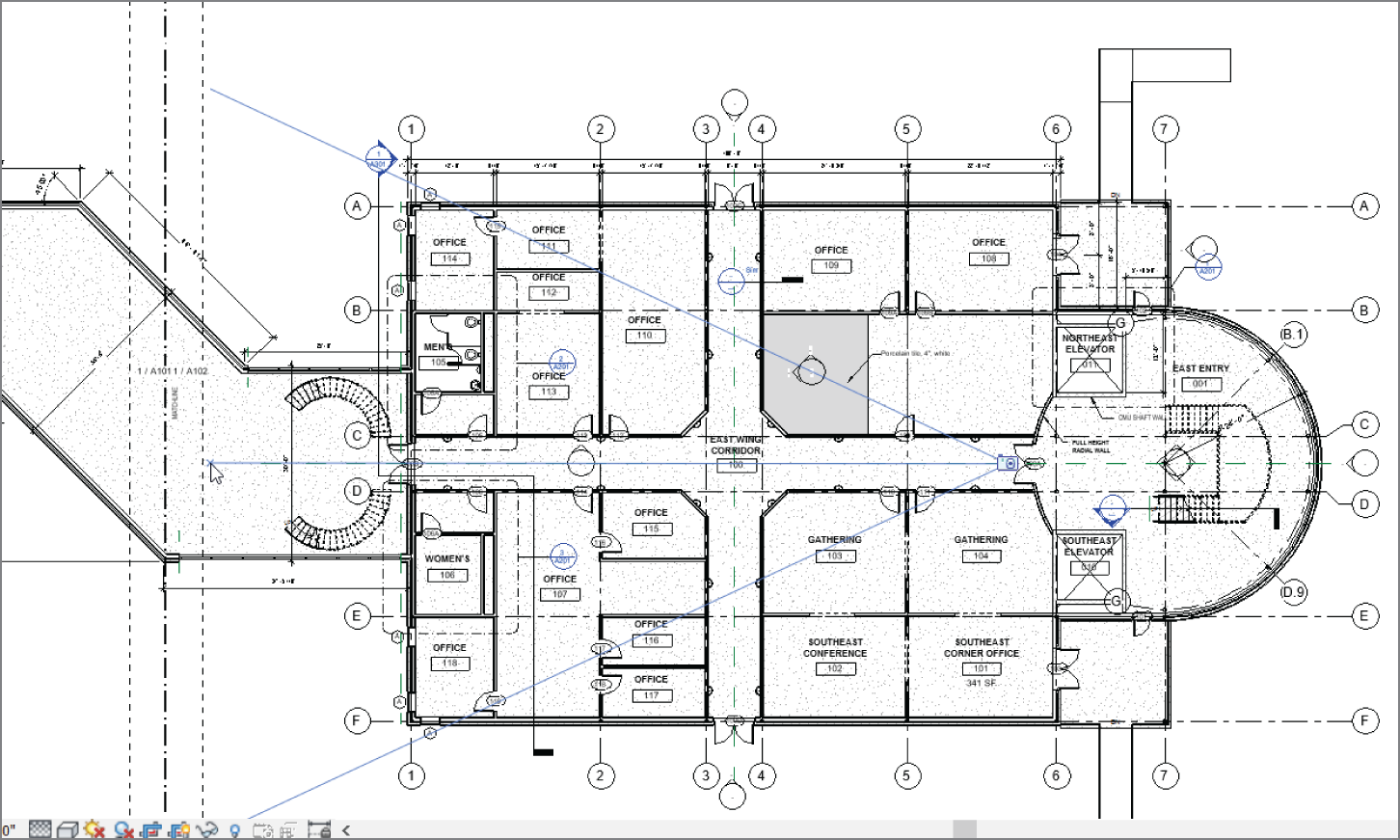
FIGURE 17.12 Creating the perspective view
- Rename it Corridor Perspective.
- In the Corridor Perspective view, select all the troffers in the ceiling and add them to the lighting group, as shown in Figure 17.13.

FIGURE 17.13 Assign the corridor lights to the correct group
- Type VG for Visibility Graphics and turn off Structural Columns.
- On the View tab, click the Render button, as shown in Figure 17.14.
- Keep the settings as shown in Figure 17.14.
- Click the Artificial Lights button.
- Make sure Lighting Corridor is selected.
- Deselect Ungrouped Lights (see Figure 17.15).
- Click OK.
- Click Render.
- Adjust the exposure to suit your needs. See Figure 17.16.
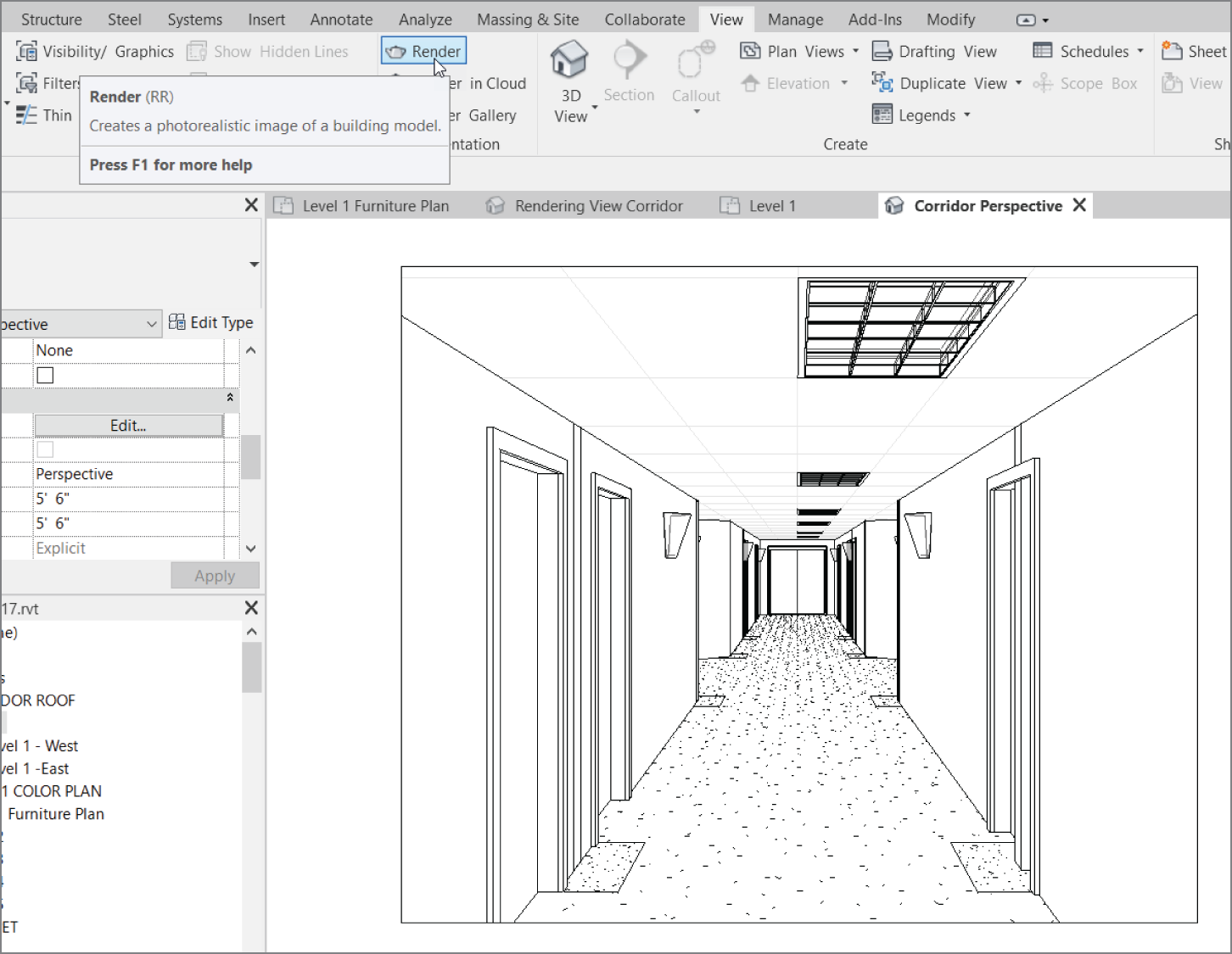
FIGURE 17.14 Finding the Render command on the View tab
Creating Walkthroughs
For some reason, you can show a client a beautiful rendering of a space or building that you plan to design for them and still be met with a blasé, halfhearted reaction. But if you show them the same space as though you're walking through it … well then, the client perks right up!
Although this part of the chapter isn't crucial to your expertise in Revit, it's certainly worth a glance. Sometimes the special tools you pull out of your belt can win a job or impress your friends on a Saturday night.
A walkthrough is a series of points you pick in a sequence in a plan view. It's sort of like connecting the dots, but these dots will advance a frame as if you were walking to the points you picked.
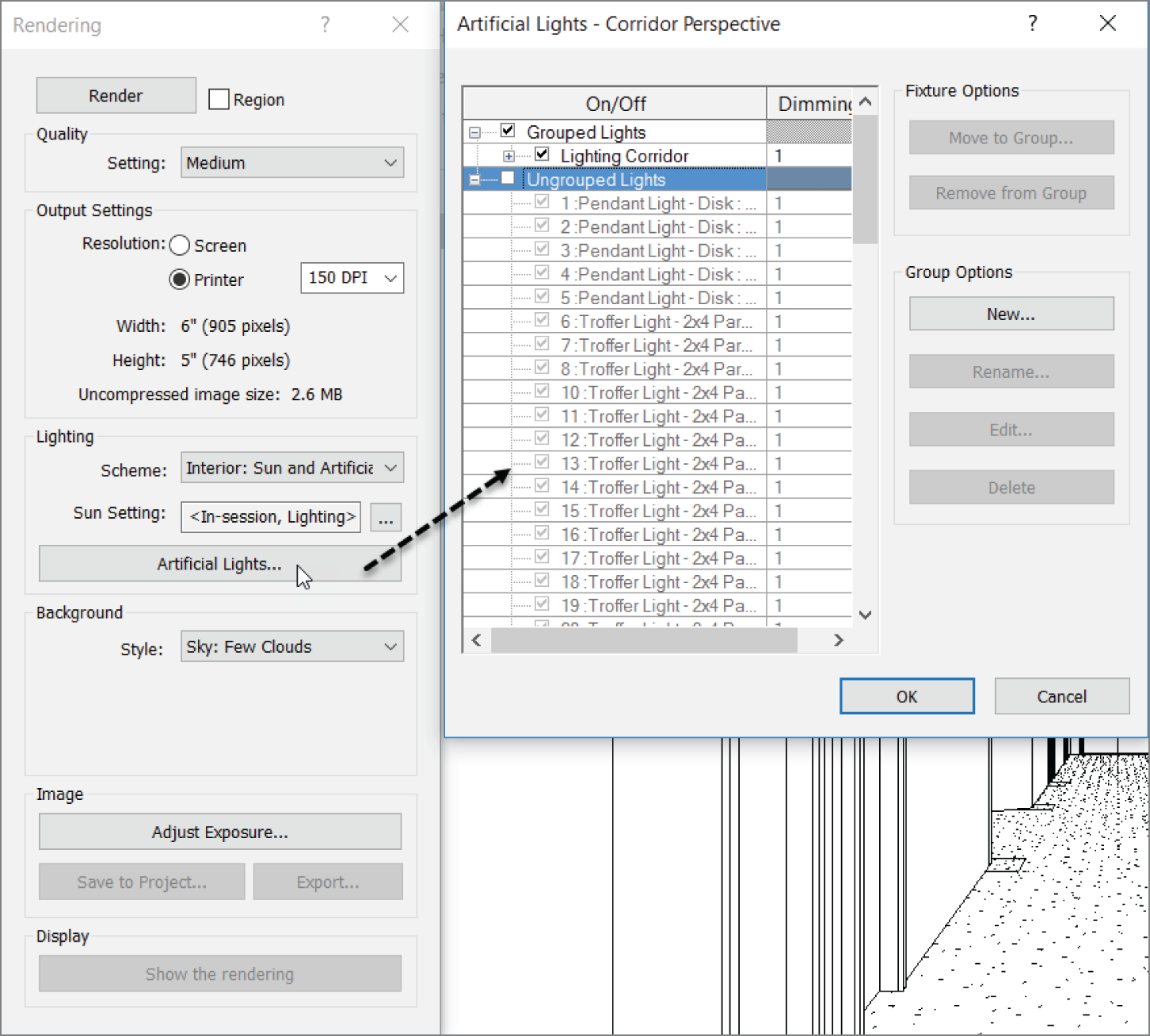
FIGURE 17.15 Choosing the lighting group to be included in the rendering
The objective of this procedure is to create a walkthrough of the building and to export the walkthrough to an AVI (Audio Video Interleave) file. Follow these steps:
- Go to the Level 1 floor plan.
- On the View tab, choose 3D View ➣ Walkthrough, as shown in Figure 17.17.
- Zoom in on the east entry.
- Start picking points, as shown in Figure 17.18.
- Keep picking points down the hallway, into the corridor, and into the east wing, as shown in Figure 17.19.
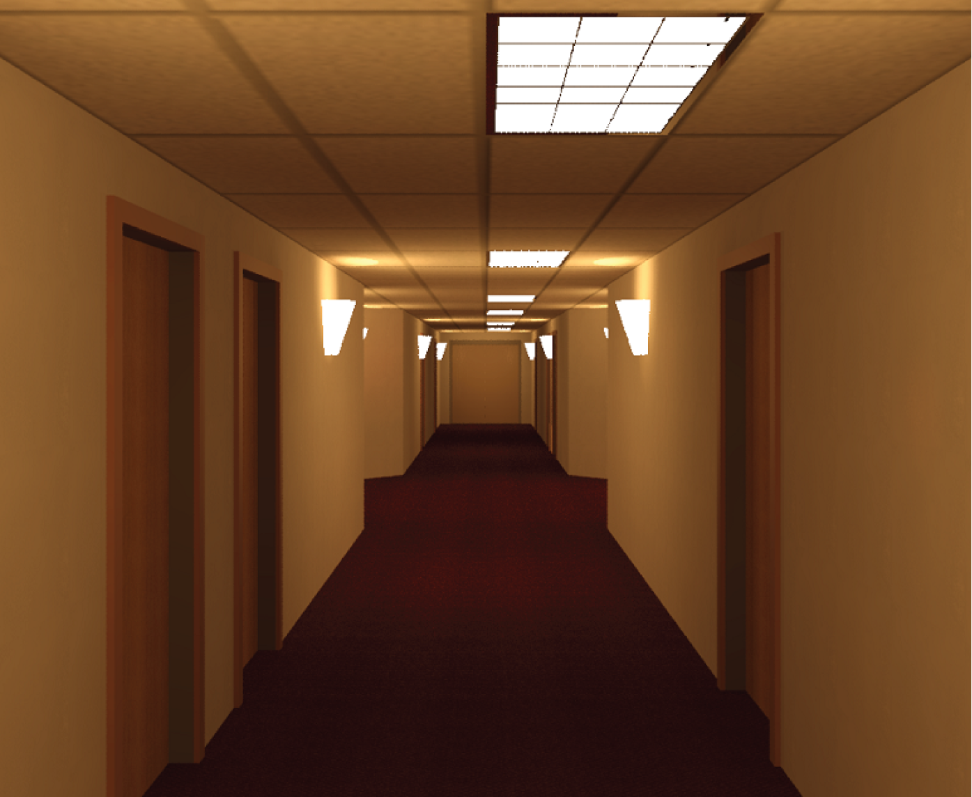
FIGURE 17.16 The corridor rendering

FIGURE 17.17 The Walkthrough command
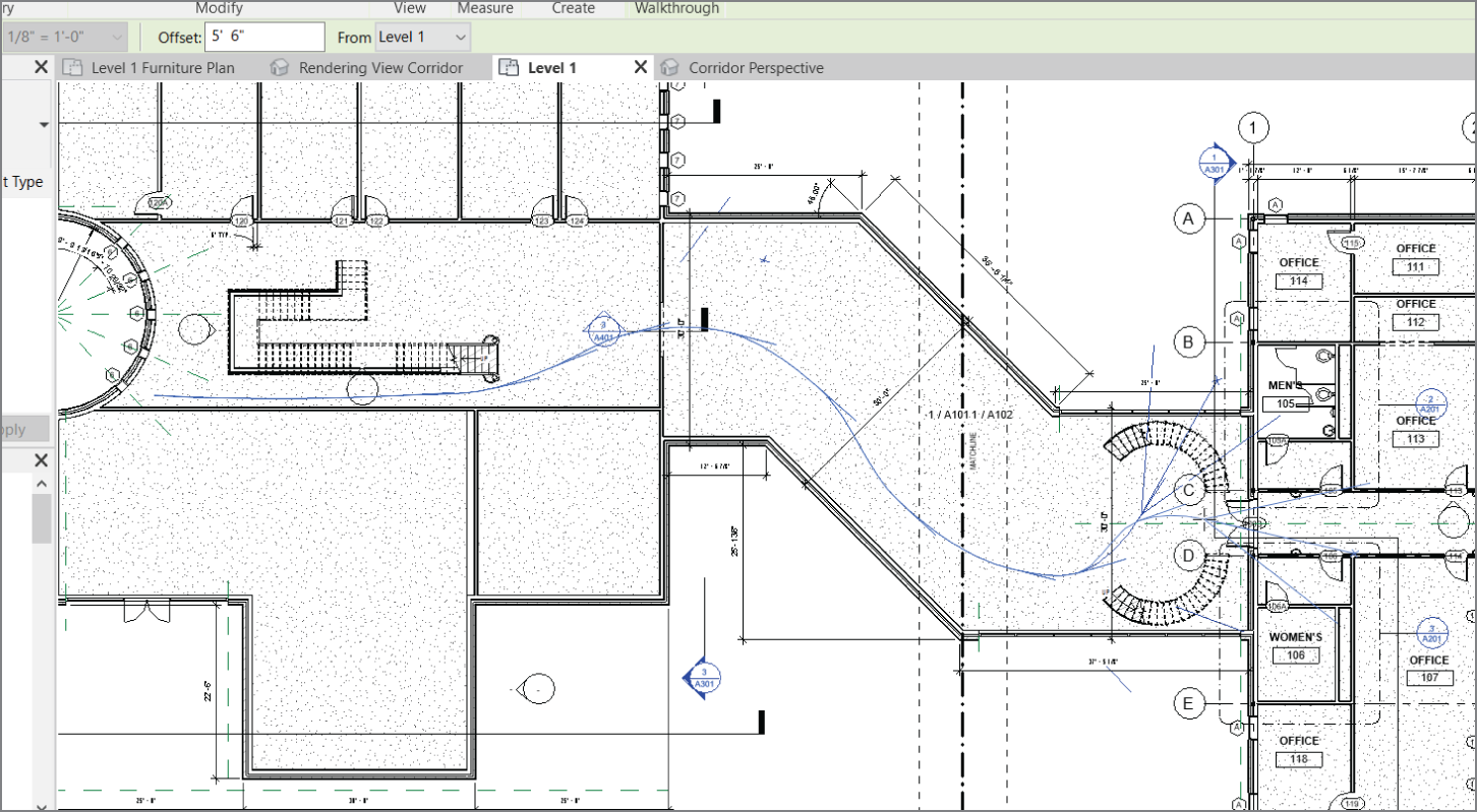
FIGURE 17.18 Picking the points in the floor plan

FIGURE 17.19 Sketching the walkthrough path
- On the Modify | Walkthrough tab of the Ribbon, click the green Finish Walkthrough check mark.
- On the Modify | Cameras tab of the Ribbon, click the Edit Walkthrough button, as shown in Figure 17.20.
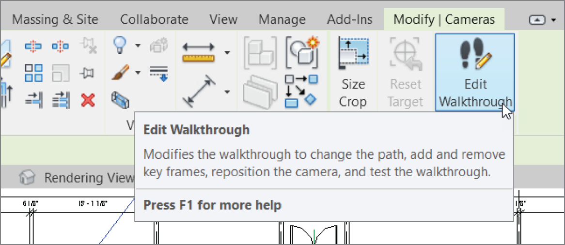
FIGURE 17.20 Selecting Edit Walkthrough
- Select Open Walkthrough, as shown in Figure 17.21.

FIGURE 17.21 Selecting Open Walkthrough
- On the Options bar, change the first frame to 1.
- On the View Control bar, click Realistic.
- Select the crop region.
- On the Modify | Cameras tab, click the Edit Walkthrough button (again).
- On the Modify | Cameras tab, click the Play button, as shown in Figure 17.22.
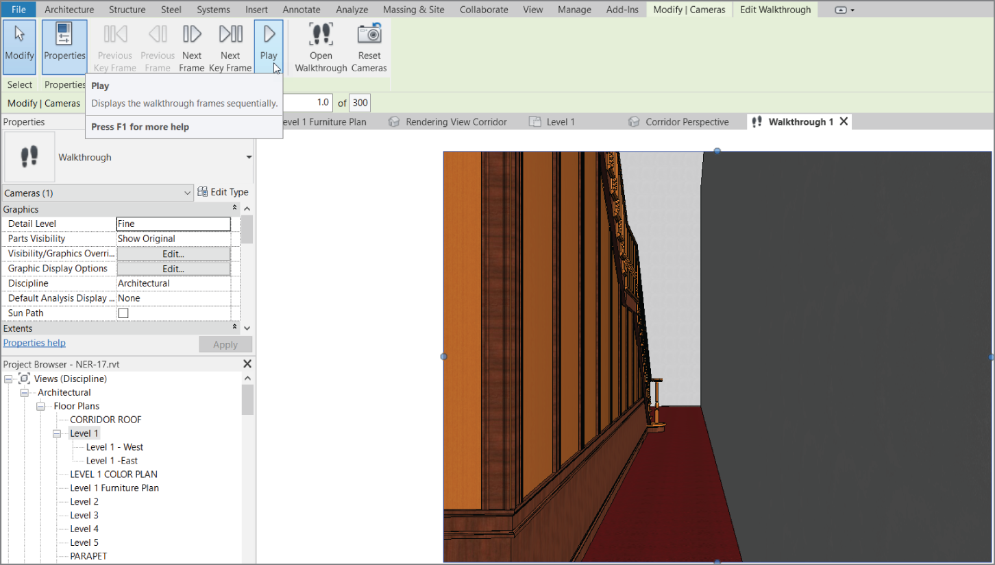
FIGURE 17.22 Clicking the Play button to start the walkthrough
- When the walkthrough is finished, click the button that contains the value 300 (the number of frames) on the Options bar, as shown in Figure 17.23.
- In the Walkthrough Frames dialog, change the Frames Per Second value to 20. Click OK.
- Run the walkthrough again. This time it's sped up.
The walkthrough is complete. One thing you will be asked is whether you can give the walkthrough to someone to use for a presentation. Luckily, the answer is yes, and the person presenting doesn't have to be Revit literate or even own the application.
Exporting an Animation
Exporting an animation is a great, but slightly hidden, feature. The Export function isn't located on the Ribbon—you'll find it on the File tab, as shown in Figure 17.24. By exporting a walkthrough, you're creating an Audio Video Interleave (AVI) that will translate the native Revit walkthrough. It's quick and almost completely painless.
To create an AVI of the walkthrough, follow these steps:
- Make sure the walkthrough view is open, and click the blue File tab.
- Choose Export ➣ Images And Animations ➣ Walkthrough (see Figure 17.24).
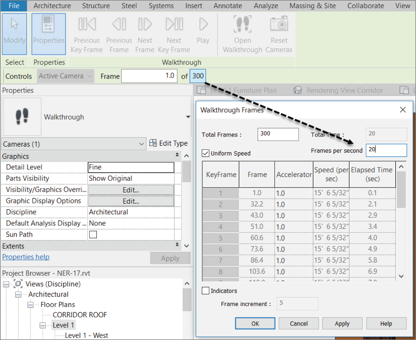
FIGURE 17.23 Changing the frames
- Select the defaults in the next dialog and click OK.
- Find a location for the file and click Save.
- Click OK in the Video Compression dialog. (You'll have to wait for Revit to go through the walkthrough as it creates the AVI.)
- Find the AVI and run it to make sure it works.
With the walkthrough complete, there is one more animation we need to look at. It's not as cool as the walkthrough, but it's just as interesting. This animation is called a solar study.

FIGURE 17.24 Choosing to export the walkthrough
Creating a Solar Study
A solar study is a shaded 3D view that provides a time‐lapsed visual of how the building will cast shadows over the course of a day or multiple days. Let's create a single‐day solar study by specifying the geographical location of your building. Follow along:
- Go to the view {3D} in the Project Browser.
- Right‐click and choose Duplicate View ➣ Duplicate With Detailing.
- Rename the new 3D view One Day Solar Study.
- On the View Control toolbar, click the Sun Path button, and choose Sun Settings.
- In the Sun Settings dialog, click the Single Day radio button, as shown in Figure 17.25.
- Set Location to Syracuse, NY (or wherever you find yourself these days).
- Change Date to 5/10/2020. Select Sunrise To Sunset. Set Ground Plane At Level to Level 1.
- Set Time Interval to One Hour (see Figure 17.25).
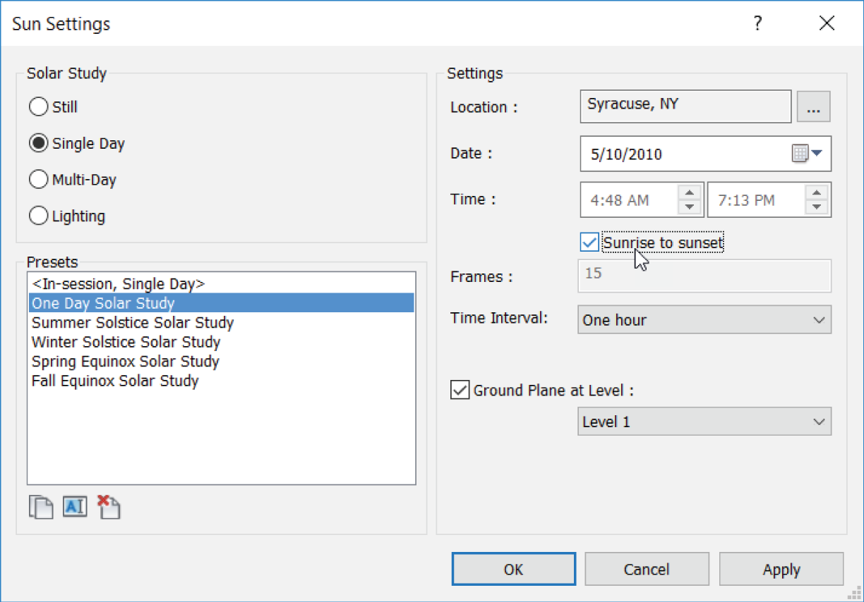
FIGURE 17.25 Setting up the solar study
- Click OK.
- Click the Sun Path button again, and turn on the sun path.
- On the View Control bar, click the Shadows button, and then select Preview Solar Study, as shown in Figure 17.26. (You can spin the view to check out the different sunlight effects on the building.)
- On the Options bar, click the Play button, as shown in Figure 17.27.
Animations such as solar studies and walkthroughs are unique features of Revit that aid you in capturing your work. Keep these features in mind the next time you're working up a proposal or a presentation.

FIGURE 17.26 Previewing the solar study
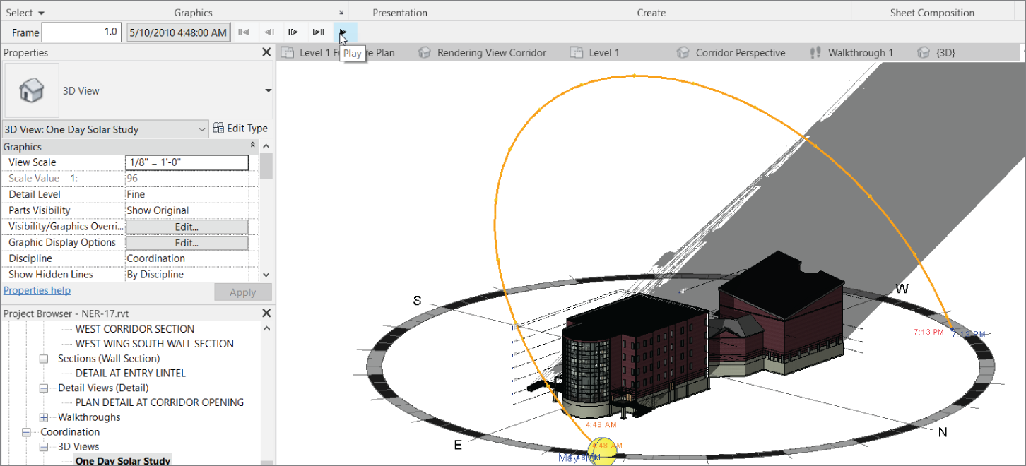
FIGURE 17.27 Clicking Play to start the solar study
Are You Experienced?
Now you can…
- create an interior rendering using a mixture of day lighting and artificial lighting
- create a walkthrough and export it to an AVI
- create a solar study that allows you to visualize the shadowing effect of your model