
CHAPTER 11
Detailing
Simply put, if detailing doesn't work, then you'll use the Autodesk® Revit® software only as a schematic design application. It's imperative that you can detail efficiently in Revit. When firms fail in their attempt to use Revit, in many cases it's because of detailing. In fact, many who have bought this book may jump straight to this chapter. And why is that? It's because many people (including me) buy into the concept of really cool 3D perspectives and one‐button modeling.
This chapter covers the following topics:
- Working with line weights
- Drafting on top of the detail
- Adding notes
- Creating blank drafting views
Working with Line Weights
When you understand Revit, you find out immediately that the real hurdle in getting it to work lies in the detailing. Sure, you can cut sections and create callouts, but how do you add that fine level of detailing needed to produce a set of documents that you're willing to stamp and sign? This chapter addresses the issues surrounding detailing.
Line weights in Revit work two ways. First there are global line weights. This is what we are going to adjust in the next series of steps. What I mean by global line weights is the project‐wide default line weights when you start a Revit project. These line weights are object based. For example, if you add a door to your model, that door's jamb, panel, and even door swing will have line weights associated with them consistently throughout the project. Second, there are view‐specific line weights. We call these Visibility Graphics Overrides. This allows us to change (override) the display of any object on a view‐by‐view basis and even on an object‐by‐object basis. Luckily, we don't need layers to do this. We will examine Visibility Graphics Overrides thoroughly in the next chapter.
To begin, we will examine global line weights, so open the file you've been using to follow along, or go to the book's web page at www.wiley.com/go/revit2020ner. From there, you can browse to the Chapter 11 folder and find the file called NER‐11.rvt.
The objective of this procedure is to format some line weights and to see where and how they're displayed by Revit:
- In the Project Browser, go to Floor Plan Level 1.
- Make sure the Thin Lines button is not active, as shown in Figure 11.1.

FIGURE 11.1 Turning off Thin Lines makes it so you can see all of your line weights exactly how they will print.
- Zoom in on the east area of the east building. This is where the radial entry is and the stairs we added in the previous chapter. I'd like to format the line weights of the stairs, the callouts, and the text leaders.
- On the Manage tab, click the Object Styles button, as shown in Figure 11.2.
Notice this dialog is broken down into tabs across the top. Since there are so many categories in Revit, this makes it easy to find what you are looking for. As we start adding links, file sharing, and design options to Revit, you will start seeing more tabs. For now, we will focus on these four tabs. These categories are embedded into Revit and cannot be changed or added to. Notice the current tab is the Model Objects tab. This covers all the 3D objects in your model.
- Scroll down to the Stairs category. Notice you can expand that category to “drill” into the overall stairs category. These subcategories will allow us to view the line weights of every aspect of the stairs.
- Change the Projection line weight for Stairs to 3, as shown in Figure 11.3.

FIGURE 11.2 Finding the Object Styles dialog
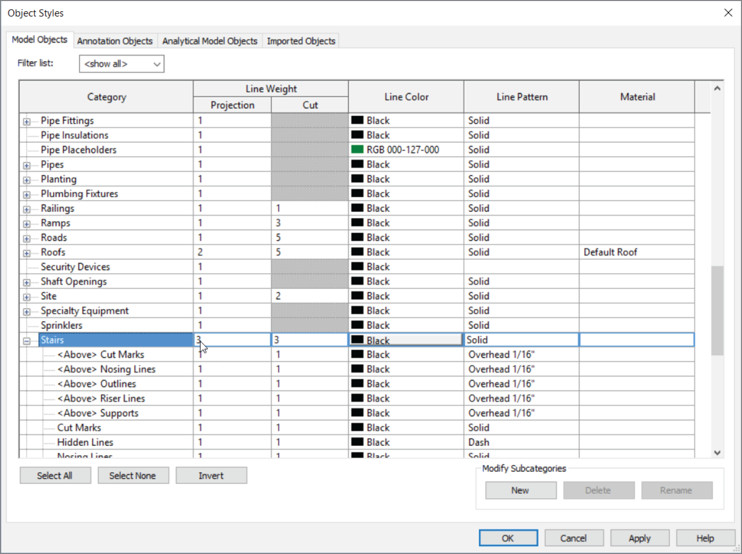
FIGURE 11.3 Finding the Stairs category and changing the Projection line weight to 3
- Find Floors, and change Cut Line Weight to 4.
- Find Walls, and change Cut Line Weight to 4.
- Go to the Annotation Objects tab.
- Change Callout Boundary to 5.
- Change Callout Leader Line to 2. See Figure 11.4.
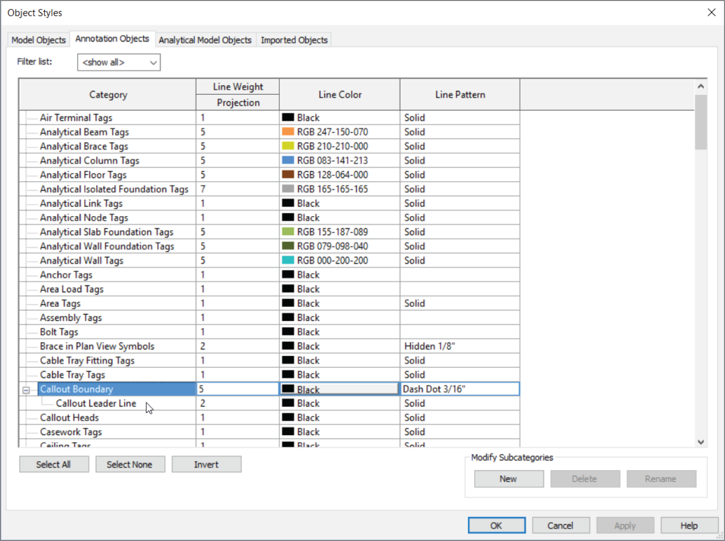
FIGURE 11.4 Change the callout.
- Click OK. Your plan now changes in appearance.
Drafting on Top of the Detail
As mentioned before, Revit provides a good number of 2D details that you can insert at any time. When Revit doesn't have the component you need, you can always create one. It isn't that hard to do.
In this section, you'll physically create a detail. The procedures you'll apply consist of adding detail components, linework, and filled regions and doing some good old‐fashioned drafting!
Using Predefined Detail Components
The first procedure focuses on inserting predefined detail components. The great thing about this is that you'll do nothing you haven't done repeatedly throughout this book—it's just a matter of finding the right button to get started:
- Open the section called Roof Taper Section.
- Go to the Annotate tab, and in the Detail panel, click Component ➣ Detail Component, as shown in Figure 11.5.
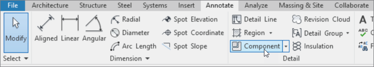
FIGURE 11.5 The Annotate tab
- Click Load Family.
- Browse to the
Detail Itemsdirectory. (It's located in theUS Imperial Librarydirectory.) - Open the
Div 01‐Generalfolder. - Click the file called
Break Line.rfa. - Click Open.
- In the Type Selector of the Properties dialog, be sure Break Line is selected, as shown in Figure 11.6.
- Press the spacebar twice. (This flips the break line into the correct orientation.)
- Pick a point like the one shown in Figure 11.6.
The next step is simply to start drafting. As mentioned earlier, you're going to get only so far with 3D modeling before you must take matters into your own hands and draft. You can approach this in Revit by taking the parts of the detail you want to keep and hiding the rest. After you hide portions of the detail, it's time to begin adding your own ingredients, such as detail components and lines.
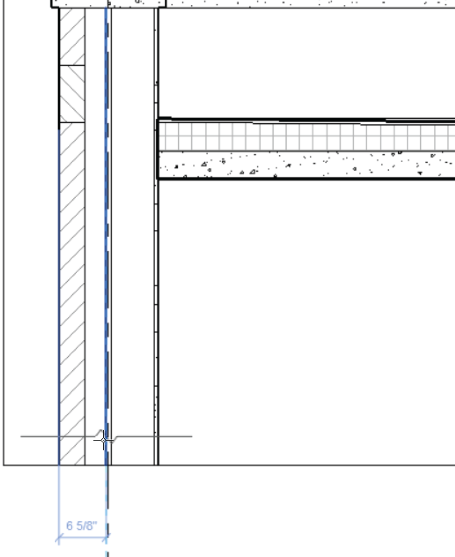
FIGURE 11.6 Placing the break line and flipping the component
Materials
Materials play an important part of Revit. We think of materials as a tool for rendering. Although this is true, it's not the full use of materials in Revit. Materials allow us to specify hatch patterns when we cut sections. By making a few material edits, we can gain control over how the out‐of‐the‐box sections look! Let's see how we can edit materials to behave correctly in Revit.
- On the Manage tab, click the Materials button, as shown in Figure 11.7.
- Type concrete in the search panel.
- Select Concrete Precast.
- For Cut Pattern, change the Foreground pattern to <none> by clicking on the picture of the pattern and finding <No pattern> at the top of the Fill Patterns dialog.
- Change Background Pattern to Concrete, as shown in Figure 11.7.
- Click OK.
- In the Roof Taper Section properties, click Visibility Graphics Overrides, as shown in Figure 11.8.

FIGURE 11.7 We have two different places to add hatch to a material.
- Find and select Walls.
- For Cut Patterns, click the Override button.
- Deselect Background Visible for Pattern Overrides. This allows us to show hatch on one wall subelement and not on another. The reason we want to do this is because we want to draft over the bricks without having that annoying hatch in our way (see Figure 11.8).
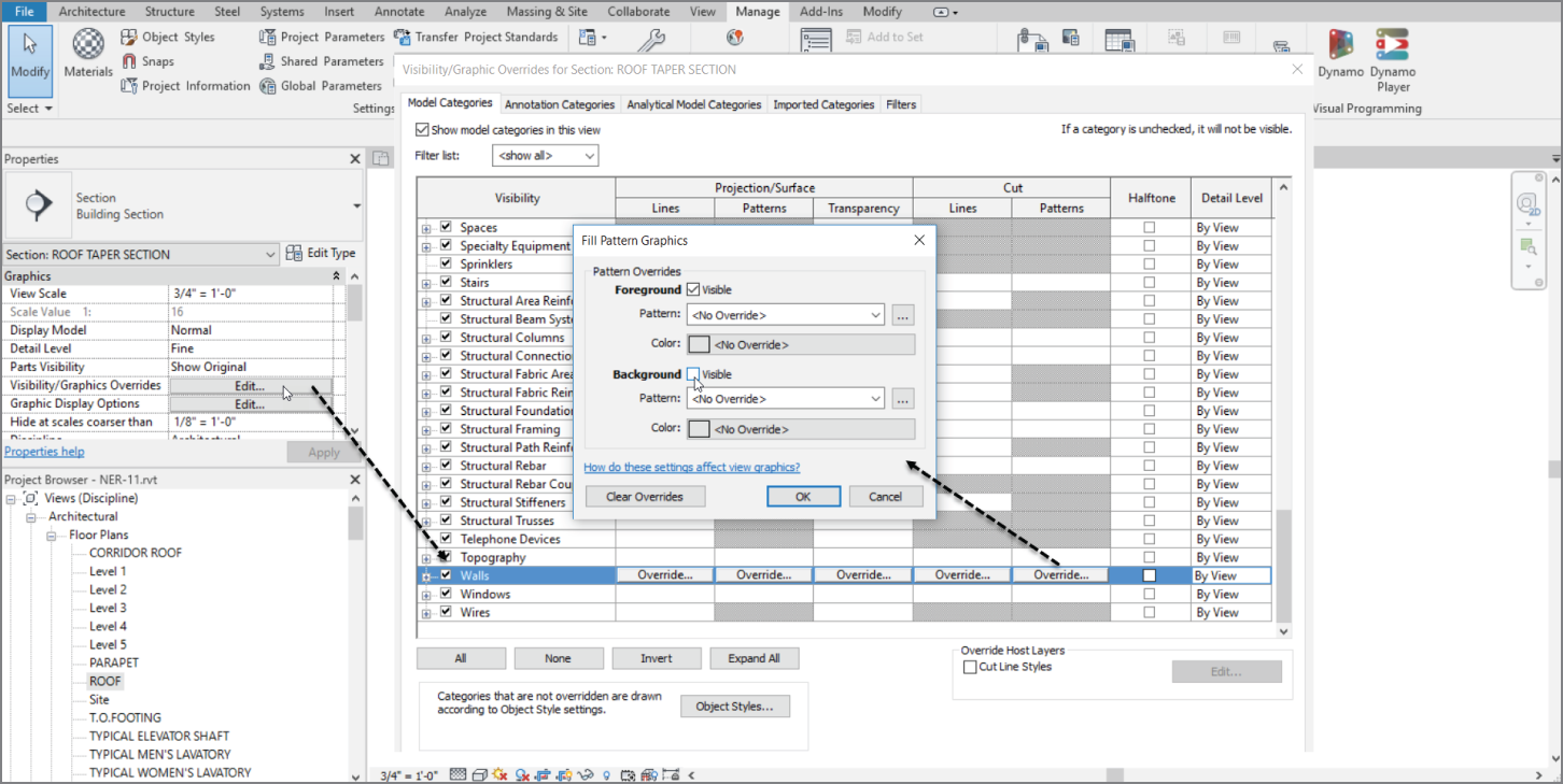
FIGURE 11.8 Choosing which hatch to show
- Click OK.
Repeating Details
Revit has a technique that allows you to add a detail component as a group. You do this by basically drawing a line; Revit then adds the detail in an array based on the points you pick.
To learn how to add a repeating detail, follow this procedure:
- In the Detail panel of the Annotate tab, select Component ➣ Repeating Detail Component, as shown in Figure 11.9.
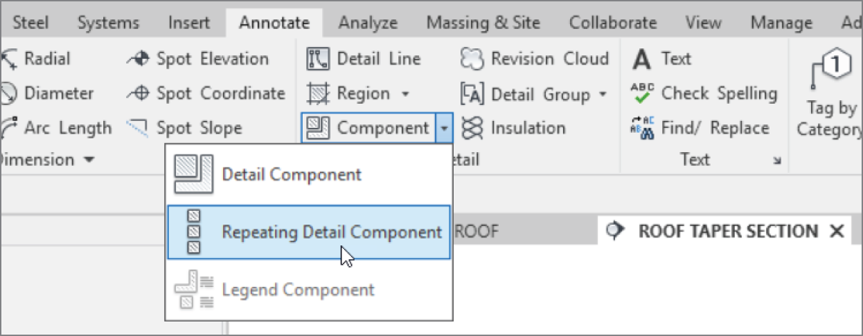
FIGURE 11.9 Select Component ➣ Repeating Detail Component.
- In the Properties dialog, choose Repeating Detail: Brick from the Type Selector.
- Pick the point labeled 1 in Figure 11.10.
- After you pick the first point, move your cursor down the view.
- Pick the endpoint 8″ (203 mm) down, as shown in Figure 11.10, so that three copies of the brick section are placed.
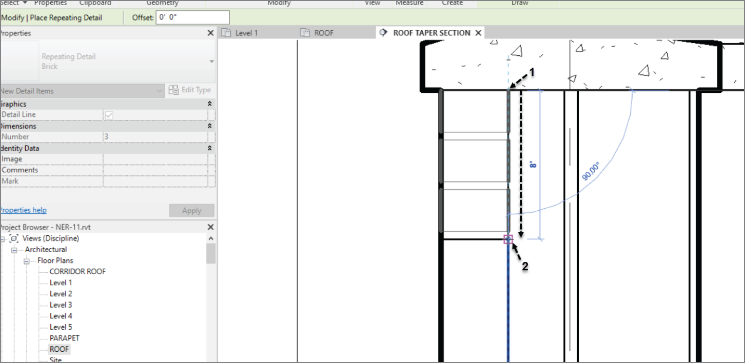
FIGURE 11.10 The first repeating detail
Let's keep going with the repeating detail. The problem you're facing is that you need to deal with the soldier course in the exterior wall. You can add that in a moment. Right now, complete the brick down past the break line.
If you feel as though you're getting the hang of adding the repeating brick detail, go ahead and add the second repeating detail. If you would like some instruction, follow along:
- Click the Component ➣ Repeating Detail Component button in the Detail panel of the Annotate tab.
- Pick point 1, as shown in Figure 11.11.
- Press the spacebar.
- Pull the cursor straight down, and pick point 2 (see Figure 11.11). Make sure you pick the second point well past the break line, or the brick will stop short.
- Press Esc twice. Look at Figure 11.12. Does your detail look the same?
- If the repeating detail is obscuring the break line, select the break line.
- In the Arrange panel, click the Bring To Front button, as shown in Figure 11.12. The repeating detail is now behind the break line.
The next step is to add the soldier course. You'll do this the same way you added the break line. In this respect, Revit offers a good library broken down into the Construction Specifications Institute (CSI) format.
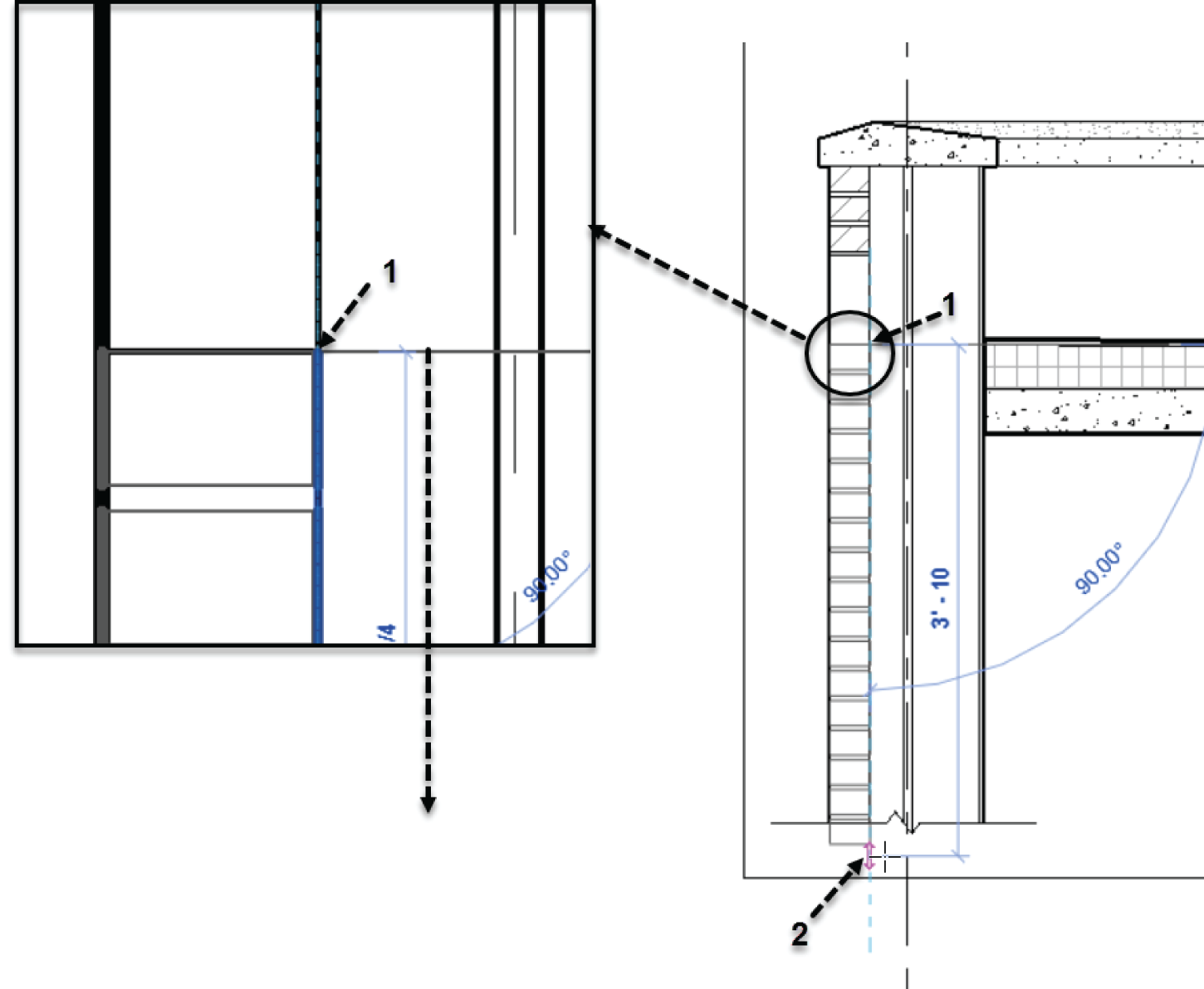
FIGURE 11.11 Picking two points
To add the soldier course, follow along:
- In the Detail panel of the Annotate tab, click the Component ➣ Detail Component button.
- In the Type Selector in the Properties dialog, select Brick Standard: Soldier & Plan.
- Press the spacebar until it's flipped as shown in Figure 11.13, and place the new detail component into the model as shown.
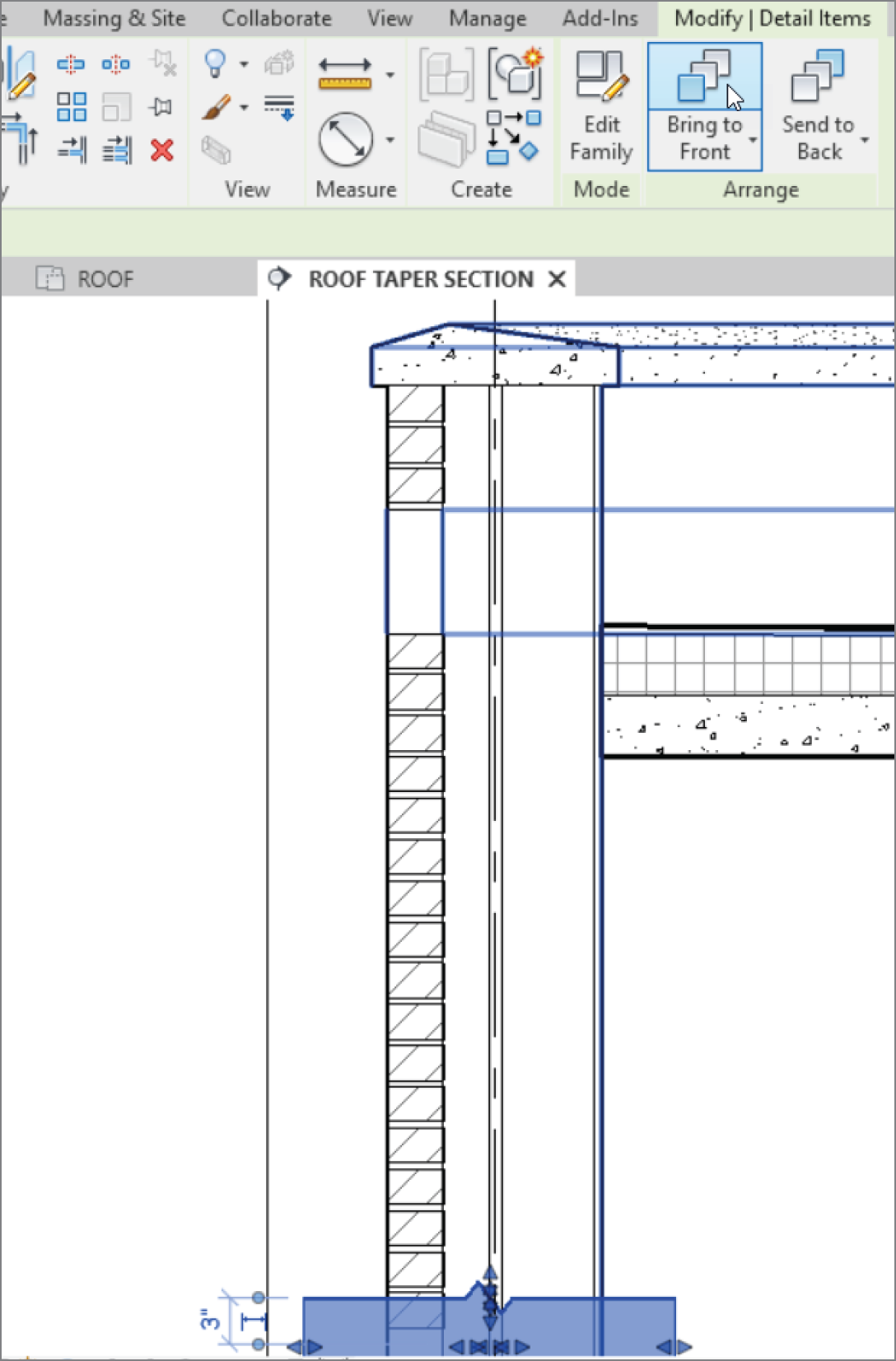
FIGURE 11.12 The bricks are being placed.
Well, the soldier course is in place, but that fat line weight is horrendous. It would be nice if everything that came out of the Revit box looked nice and met your specifications—but alas, that isn't the case. Let's modify this component to make it presentable.
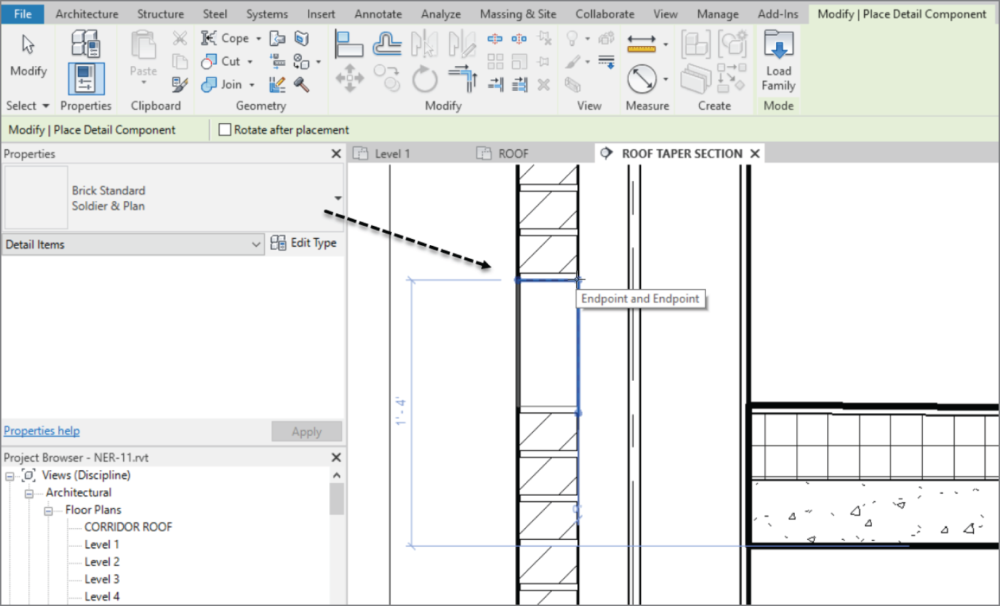
FIGURE 11.13 Placing the new detail component
Modifying a Detail Component
Right about now is when every CAD/BIM manager around the globe raises an eyebrow—for good reason. Revit allows you to modify a component by actually opening the file! But don't worry; you have to issue a Save As command to save the detail.
The objectives of the following procedure are to create a texture on the brick detail and to use a line weight that the user can control in the model:
- If you still have a command running, click the Modify button to the left of the Ribbon, or press the Esc key.
- Select the Bricks ‐ Standard Soldier & Plan family that you just placed.
- On the Modify | Detail Items tab, click the Edit Family button, as shown in Figure 11.14.
- The next dialog may ask you if you want to open this file to edit it. Click Yes if you get that message.
The detail component family is now open. It's time to operate, Doctor. The next set of procedures will focus on modifying the linework of the brick and adding what is called a filled region.

FIGURE 11.14 Open the family for editing after selecting the detail component.
Modifying Filled Regions
A filled region is similar to a masking region in that you apply both in the same manner. A filled region, however, contains a hatch pattern that is visible when the region is completed. This is how you hatch in Revit. It takes the place of the conventional hatch command found in Autodesk AutoCAD® and MicroStation.
The goal of the next procedure is to modify the filled region that makes up the brick. You'll also use the region's outline to define the perimeter and the texture of the brick itself:
- Click the blue File tab, and select Save As ➣ Family.
- Call the new family Brick ‐ Soldier.
- Click the Family Types button, as shown in Figure 11.15.
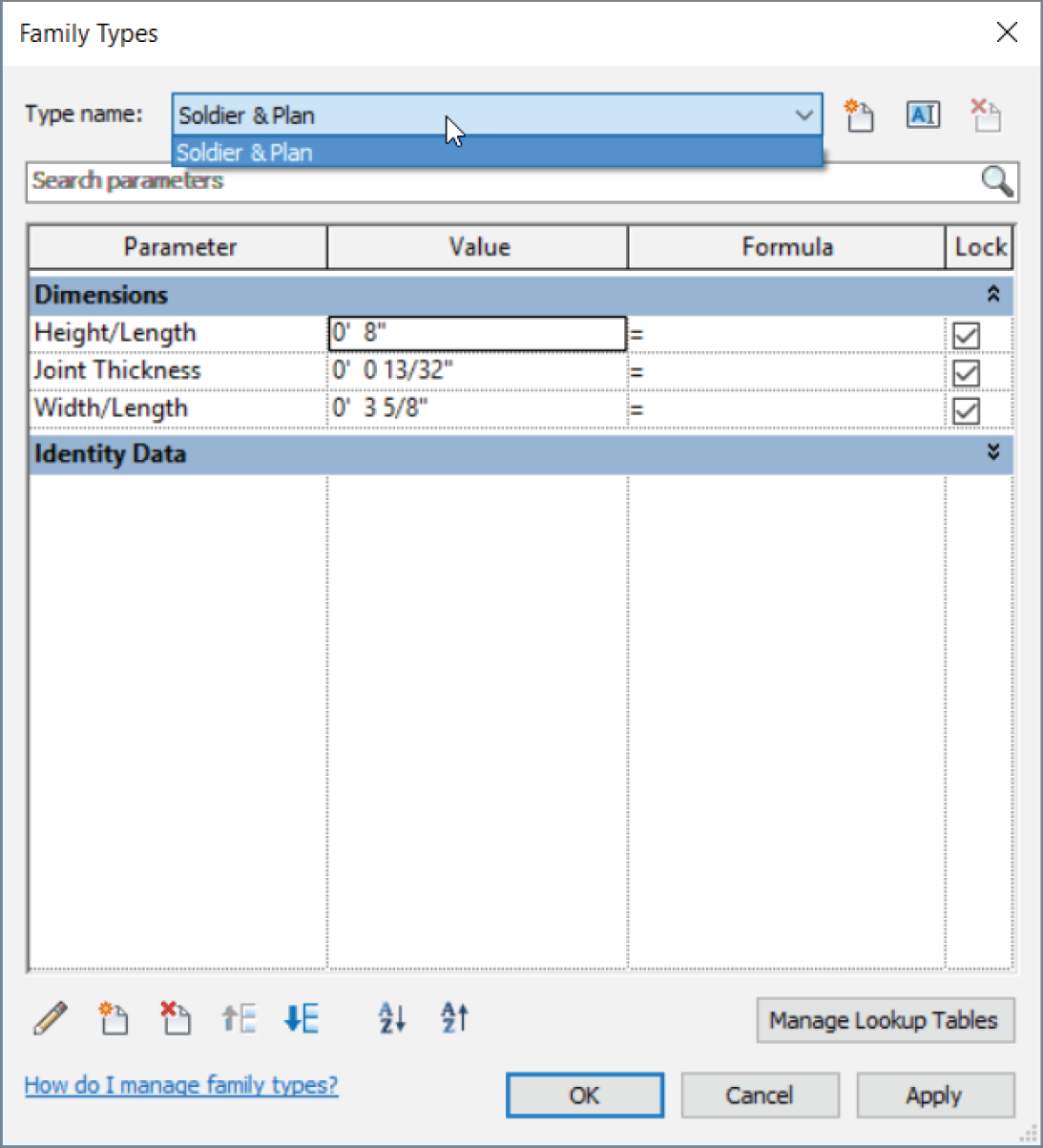
FIGURE 11.15 Cleaning out the extra types
- In the Type Name menu, make sure Soldier & Plan is selected.
- Click the Delete button at the right in the dialog.
- Click OK.
- Select the line that is hovering over the top of the brick, and mirror it to the bottom so that you have a line above and a line below the brick, as shown in Figure 11.16.
- Select one of the heavy lines that form the outline of the brick (see Figure 11.16). Revit indicates that this is a filled region, as revealed in the tooltip that appears when you hover your pointer over one of the boundaries.
- In the Mode panel of the Modify | Detail Items tab, click the Edit Boundary button (see Figure 11.16).

FIGURE 11.16 Editing the boundary of the filled region
- Delete the two thick, vertical lines.
- In the Draw panel, select the Line button, as shown in Figure 11.17.
- In the Line Style panel that appears, select Detail Items.
- Draw a series of jagged lines on the right and left of the brick, as shown in Figure 11.17.
- After you finish sketching the texture, click Edit Type.
- Change Background Fill Pattern to <Solid Fill>.
- Change Background Pattern Color to RGB 223‐223‐223, as shown in Figure 11.18.

FIGURE 11.17 Adding a texture to the brick family
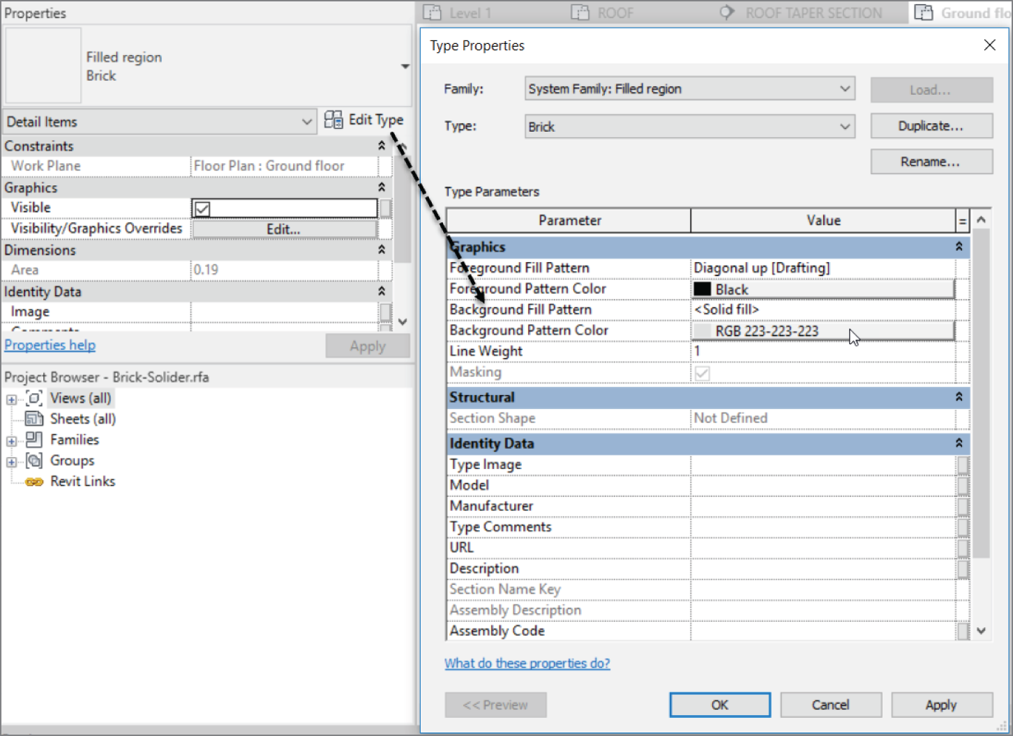
FIGURE 11.18 Changing the filled region
- Click OK.
- Click Finish Edit Mode. Your brick should resemble Figure 11.19.
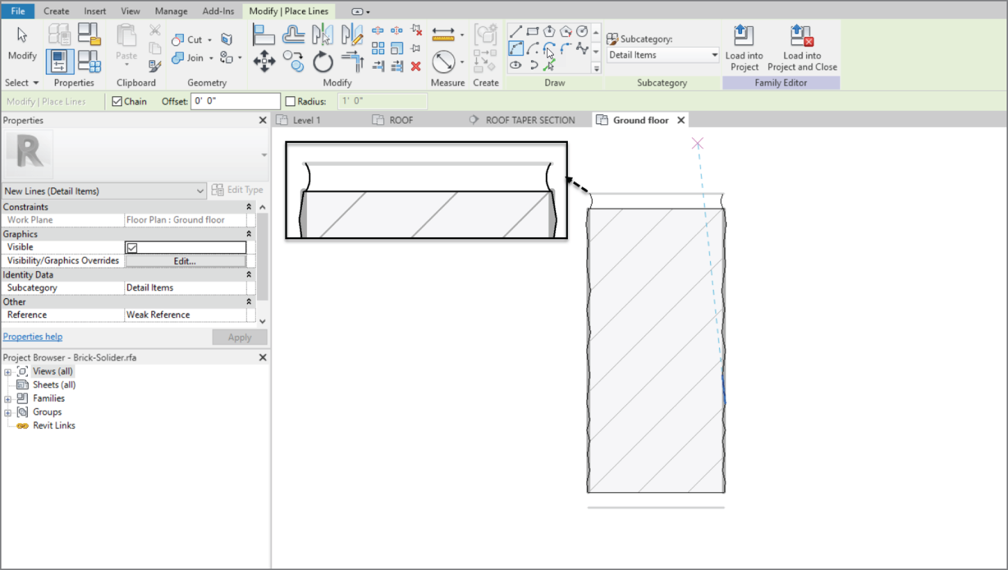
FIGURE 11.19 The finished soldier
Next, you'll add a mortar joint to the bottom of the brick. You simply add drafting lines:
- On the Create tab, click the Line button.
- In the Draw panel, click the Start‐End‐Radius Arc button.
- Draw two arcs to the left and right of the top of the brick, as shown in Figure 11.19.
- Click Save.
- Click Load Into Project and Close, as shown in Figure 11.20.
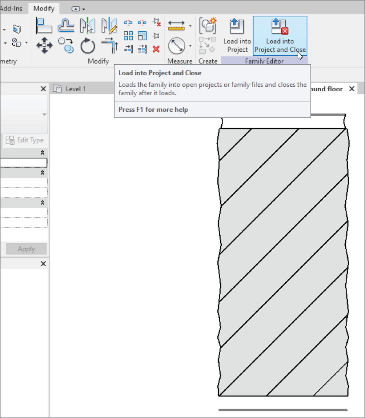
FIGURE 11.20 Load into Project and Close
- Make sure you have the Roof Taper Section open (Revit may have thrown you into another view).
- Select the smooth, boring, existing soldier.
- In the Type Selector, change it to Brick ‐ Soldier: Soldier & Plan.
- Delete the extra brick. Your wall should look like Figure 11.21.
- Save the model.
The next group of procedures focuses on editing the bricks used in the repeating detail. You certainly want the same face texture, and it would be nice if there was a mortar joint between them.
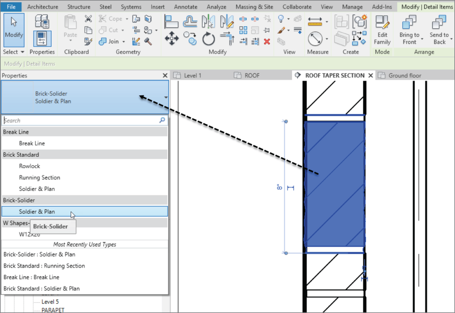
FIGURE 11.21 The new soldier brick in the model
Before you modify the bricks, let's explore how a repeating detail is created. The objective of the next procedure is to discover how a repeating detail works and how you can create a new one:
- Make sure you're in the detail called Roof Taper Section.
- Select one of the repeating details, as shown in Figure 11.22.
- In the Properties dialog, click Edit Type, as shown at the upper left in Figure 11.22.
- Click into the detail Value list. Every detail component listed in your model is available. The detail component being used here is Brick Standard: Running Section. This is the profile family we want to pretty up.

FIGURE 11.22 Click the Edit Type button after selecting one of the brick repeating details.
You can change the spacing and the patterns of how the repeating detail will perform.
- Click Cancel.
The next objective is to modify the specific detail component that the repeating detail is using. To do so, you must add an instance of the detail component (in this case, Brick Standard: Running Section) and then edit the family. After you load it back into the model, the repeating detail will be up to date.
If you would like to give it a shot and do it on your own, go ahead. If you would rather have some guidance, follow along:
- In the Detail panel of the Annotate tab, click the Component ➣ Detail Component button.
- In the Type Selector in the Properties dialog, pick the Brick Standard: Running Section detail component. (Remember, this was the component that you discovered the repeating detail was using.)
- Place the detail component off to the side of the wall, as shown in Figure 11.23.
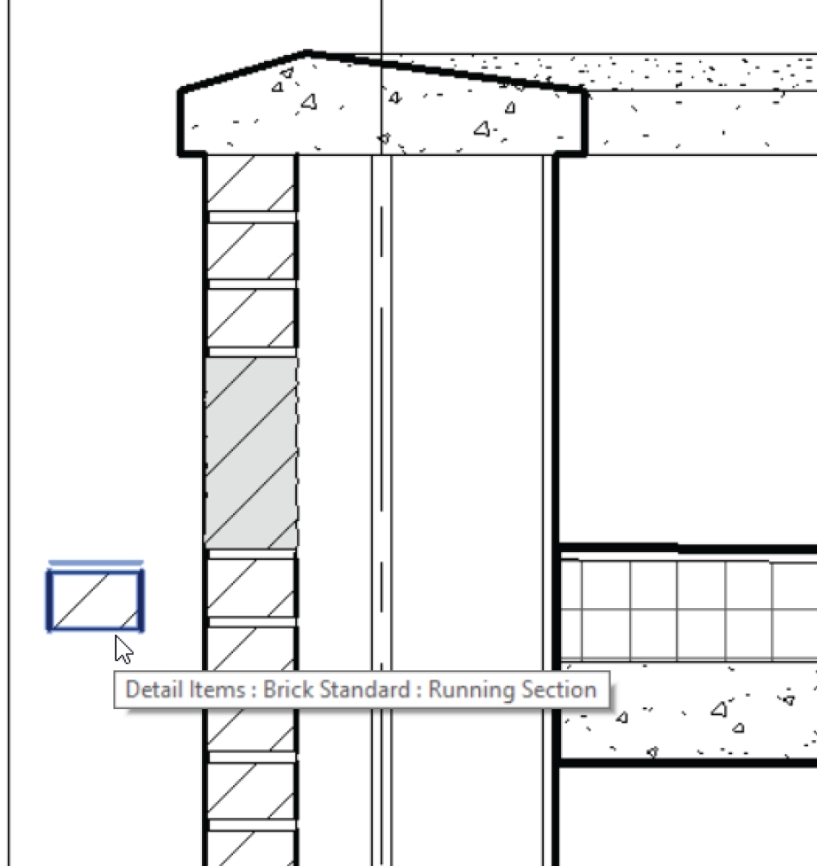
FIGURE 11.23 Place the Brick Standard: Running Section detail component off to the side. You'll delete this occurrence of the component later.
- Press Esc twice, or click Modify.
- Select the Brick Standard: Running Section that you just inserted.
- In the Mode panel, click the Edit Family button.
- Select the filled region.
- In the Mode panel, click Edit Boundary.
- Delete the right and left thick lines.
- In the Draw panel, click the Line button.
- In the Type Selector in the Properties dialog, click Detail Items.
- Draw the jagged lines on both sides, as shown in Figure 11.24.
- Click Finish Edit Mode on the Mode panel.
- On the Create tab, click the Line button.
- In the Draw panel, click the Start‐End‐Radius Arc button.
- In the Subcategory panel, be sure Detail Items is chosen from the Type Selector list.
- Draw an arc on both sides of the brick (see Figure 11.24).
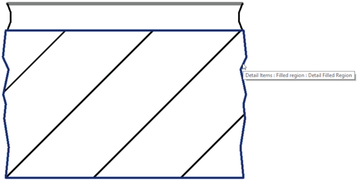
FIGURE 11.24 Draw the textured face while you're in Edit Mode for the filled region. Draw the arcs for the mortar joint using lines.
- When you're finished, save the new brick as Brick Standard. You can also find this brick on the book's web page in the
Chapter11 folder. It's calledBrick Standard.rfa. - In the Family Editor panel, click Load Into Project And Close.
- In the project, click to overwrite the family.
- Delete the stray detail component you placed. (You were using it only for access to the family.)
Compare your detail to the detail in Figure 11.25.
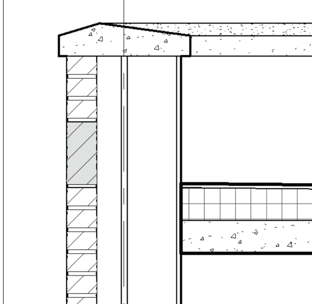
FIGURE 11.25 The brick actually looks like brick!
Notice the heavy lines on the outside and the inside of the brick façade. These are part of the wall in the model. The bad thing is, they are in the way. The good thing is, we can make them disappear in this view by simply using the Linework tool. Let's do that now.
- On the Modify tab, click the Linework button, as shown in Figure 11.26.
- In the Line Style menu, select <Invisible Lines> (see Figure 11.26).
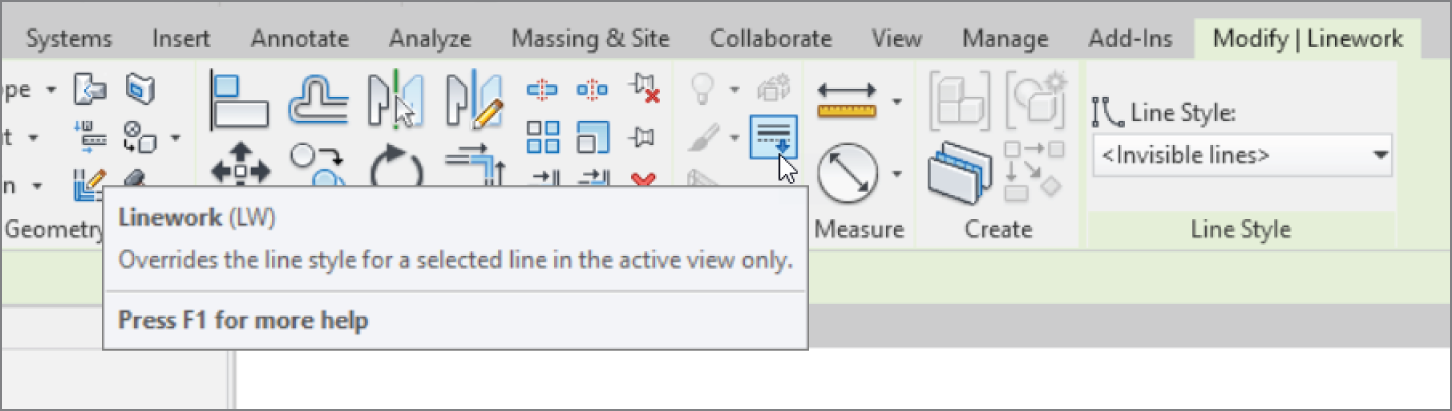
FIGURE 11.26 We can override the display of the lines in the model with the Linework tool.
- Now start selecting the lines to show invisible in this view, as shown in Figure 11.27. You will have to select the lines multiple times to remove them completely.
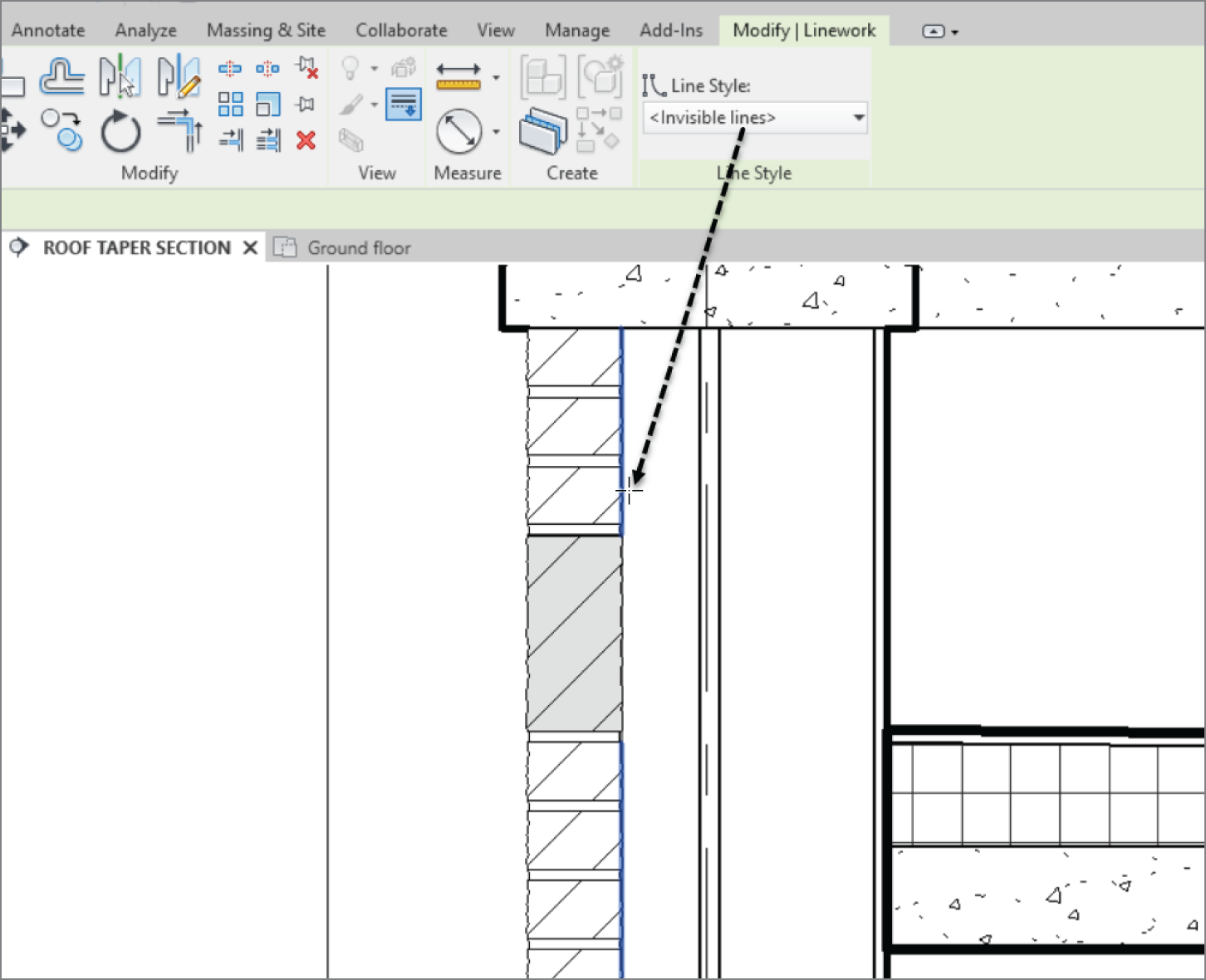
FIGURE 11.27 Selecting the lines to make invisible
Next, you'll anchor this façade back to the wall. You need to add two things: a structural relief angle above the soldier course, and a brick tieback to a lower course. Follow along:
- On the Annotate tab, click the Component ➣ Detail Component button.
- In the Mode panel, click the Load Family button.
- Open the
Detail itemsfolder. - Select
Div 05‐Metals. - Select
051200‐Structural Steel Framing. - Double‐click the file
AISC Angle Shapes‐Section.rfa. - In the Type list, select L6×4×5/16 (152×102×8).
- Click OK. You'll have to use the spacebar and flip controls to rotate and flip the instance.
- Place it into the model, as shown in Figure 11.28.

FIGURE 11.28 Placing the L6×4×5/16 (152×102×8) angle
- Press Esc twice, or click Modify.
Of course, the line weight is basically a blob, so let's take a look at object styles.
- I think Heavy Detail Items are too thin. Select the Manage tab, and then click Object Styles.
- Expand Detail Items and change Heavy Lines to 3, as shown in Figure 11.29.
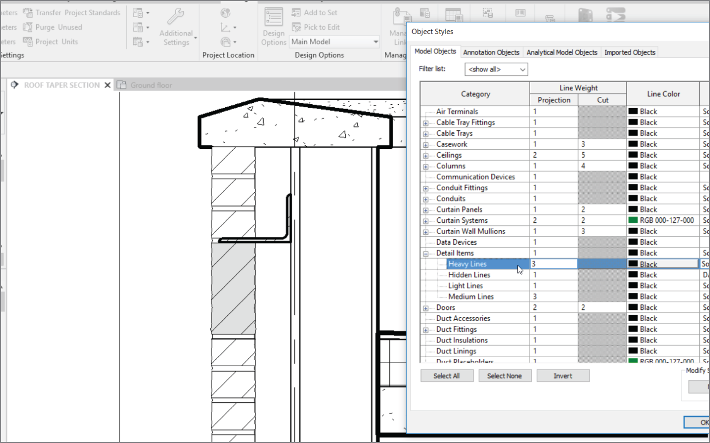
FIGURE 11.29 The angle in place and looking like an angle
The next step is to find a fastener to anchor the angle back to the wall's substrate. Since this is a metal stud wall, we will need to add some lag screws that fasten into wood blocking that will be installed between the metal studs.
- On the Annotate tab, click the Component button.
- Click Load Family.
- Browse to Detail Items ‐ Div 06‐Wood And Plastic ‐ 060500‐Common Work Results For Wood Plastics And Composites ‐ 060523‐Fastenings ‐ Lag Screws‐Side.rfa.
- Insert two lag screws into the angle, as shown in Figure 11.30.

FIGURE 11.30 Inserting the lag bolt
- Press Esc twice.
Now you'll add a corrugated wall tie to the brick below the soldier course. Because the brick is a pretty good distance away from the wall, you first need to add some wood blocking to the model:
- On the Insert tab, click the Load Family button.
- Go to the
Detail Itemsfolder. - Select
Div 06‐Wood And Plastic. - Select
061100‐Wood Framing. - Click the file
Nominal Cut Lumber‐Section.rfa. - Select the 2×6 (51×152) type, and click OK.
- Select the Annotate tab, click the Component ➣ Detail Component button, and place the 2×6 (51×152) into the wall, as shown in Figure 11.31. Also, place one behind the lag screws.
- Select the blocking the lag screws are anchored into and click the Send To Back button. See Figure 11.31.
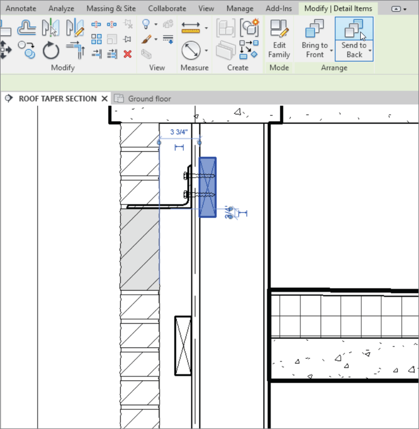
FIGURE 11.31 Adding the wood blocking
The next step is to add the corrugated wall tie. You'll do this in the same manner, except that it's located in a different directory:
- On the Insert tab, click the Load Family button.
- Go to the
Detail Itemsfolder. - Select
Div 04‐Masonry. - Select
040500‐Common Work Results For Masonry. - Select
040519‐Masonry Anchorage And Reinforcing. - Select the file called
Corrugated Wall Tie‐Section.rfa. - Use the Detail Component button to place the wall tie into your model, as shown in Figure 11.32.

FIGURE 11.32 Placing the corrugated wall tie
When you're drafting over a true section of your model, it's always good to try to use as much of the graphical information from the actual model as possible. For example, the 3/4″ (16 mm) void you see the bolt going through is actually 3/4″ (16 mm) plywood sheathing. For some reason, the default plywood material has its cut pattern set to None. Let's fix this:
- Select the wall.
- Click Edit Type.
- Click the Edit button in the Structure row.
- Click into the Material column in row 5. It's the substrate row, and the material is –Plywood, Sheathing.
- When you click –Plywood, Sheathing, you see a tiny […] button. Click it.
- On the Graphics tab, click into the Pattern field in the Cut Pattern Background category, and change the pattern to Plywood, as shown in Figure 11.33.
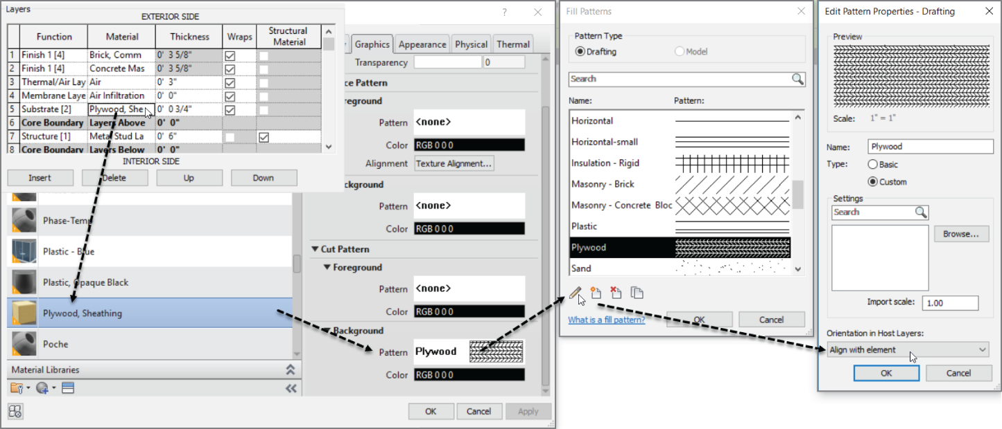
FIGURE 11.33 Show us your plywood!
- Double‐click the plywood pattern (see Figure 11.33 for the location of the cursor).
- Click the Edit button (it looks like a little pencil).
- Select the Align With Element drop‐down for the Orientation In Host Layers: field.
- Click OK three times to get back to the model. Your wall should look like Figure 11.34.
So what makes a Medium Line medium and a Thin Line thin? This is a part of Revit over which you need to have full control. After all, your biggest challenge will be getting your plotted sheets to match your old CAD‐plotted sheets. Specifying line weights is crucial.
Specifying Drafting Line Weights
In CAD, you wouldn't dare to draw even a single line if you didn't know the proper layer on which it was being drafted, right? Why should Revit be any different?
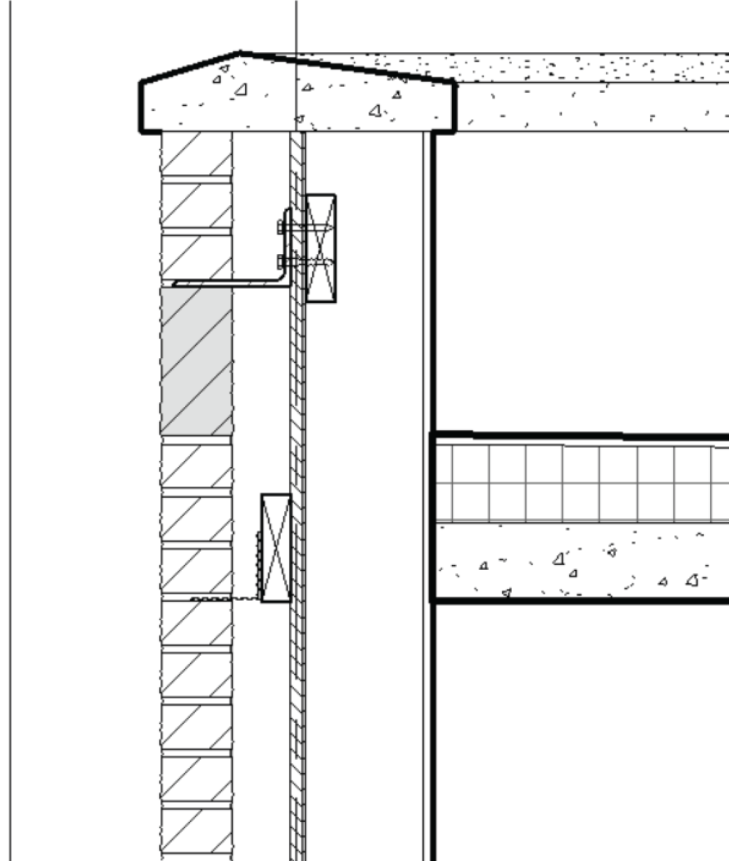
FIGURE 11.34 The wall section with the plywood substrate
The objective of the next procedure is to investigate where the line weights are stored and how they relate to the lines you're drawing:
- On the Manage tab, choose Additional Settings ➣ Line Styles.
- In the Line Styles dialog, expand the Lines category by clicking the plus sign next to Lines. Some of the line styles were generated in AutoCAD.
- Click into the Wide Lines category, and change the value from 5 to 4, as shown in Figure 11.35.
- Click OK. Wide Lines in all project views will now show the new line weight.
The next item to tackle is the fact that this detail looks naked without any text or dimensions added to it. Although you've applied both of these items in past chapters, you need to use them because they're relevant to detailing.
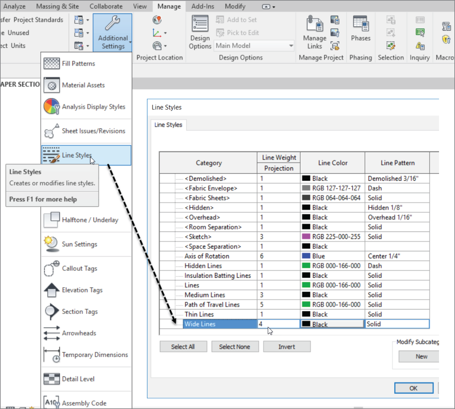
FIGURE 11.35 Changing Wide Lines from 5 to 4
Adding Notes
In Revit, adding notes to a section can take on a whole different meaning than in CAD.
Or, if you wish, adding notes to a detail can be exactly as it was back in CAD. Sometimes, sticking to the tried‐and‐true method isn't such a bad thing.
The goal of the next set of procedures is to add notes by simply leadering in some text.
Adding Textual Notations
We're duplicating efforts with text to drive home the fact that Revit lets you add text regardless of the view or the scale. Text in a plan is the same as text in a detail, and you'll prove it in the next procedure:
- On the Annotate tab, click the Text button, as shown in Figure 11.36.
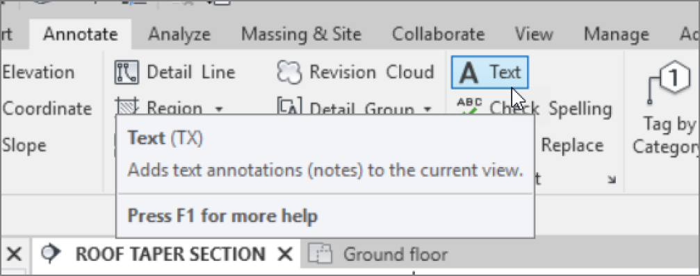
FIGURE 11.36 The Text button in the Annotate tab is also found on the Quick Access toolbar.
- In the temporary Modify | Place Text panel, select Two segments.
- Select Leader at Top Left and Top Right.
- Select Middle Align.
- Select Align Right.
- In the section, pick the first point of the leader at the top of the brick tie detail (shown in Figure 11.37).
- Pick the second point above and to the left of the first point (shown in Figure 11.37).
- Pick the third point for the second segment (as shown in Figure 11.37).
- Type the note CORRUGATED BRICK TIE ON 2X6 BLOCKING.
- Click off the text into another part of the model, and your text justifies to the leader.
- Press Esc twice.
- Select the text.
- Pick the grip to the left, and drag the box to resemble Figure 11.38. The text wraps.
- Save the model.
These steps are the most common procedure for adding detail to a model. In other words, take what you can from the model, and then add linework and detail components to the view. However, eventually you'll find yourself in a situation where you would rather draft your detail from scratch. You can do this as well, as you'll see in the next section.

FIGURE 11.37 Adding text with a leader
Creating Blank Drafting Views
Over the years, Revit has been labeled as a “poor drafting application.” I concede that AutoCAD is a better drafting program. And if all you do is 2D linework, perhaps stick with AutoCAD. But you're learning Revit, so let's see how Revit can be a very good drafting application when given the chance. The only challenge is to figure out where to start!
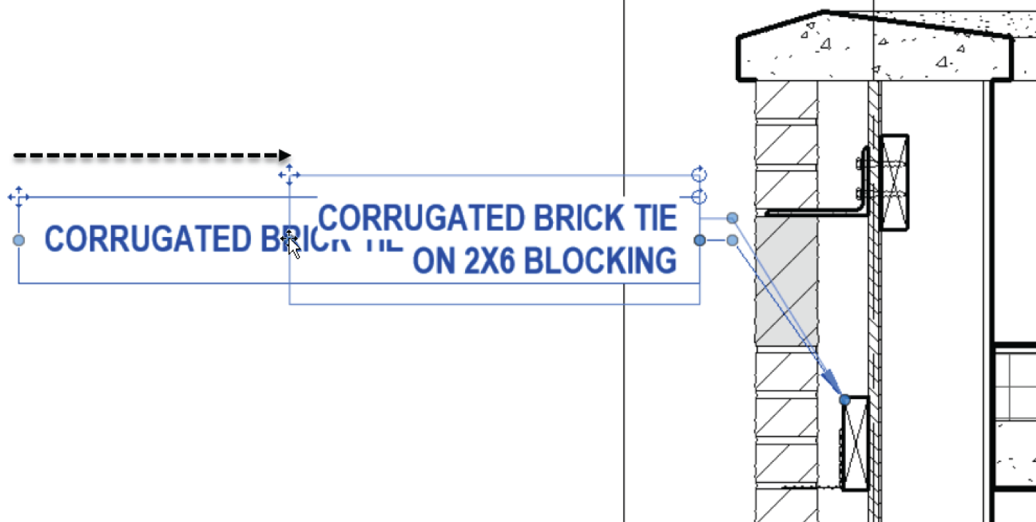
FIGURE 11.38 Wrapping the text
The objective of the next procedure is to create a blank view and then simply learn how to draw lines:
- On the View tab, click the Drafting View button, as shown in Figure 11.39.
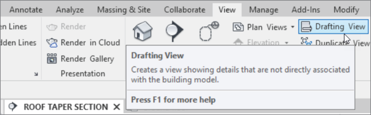
FIGURE 11.39 Click the Drafting View button on the View tab.
- In the New Drafting View dialog, name the new view TYPICAL WALL TERMINATION.
- Change the scale to 3/4″ = 1′–0″ (1:20 for metric users). See Figure 11.40.
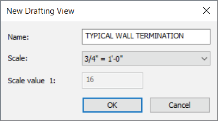
FIGURE 11.40 Changing the view name and scale
- Click OK.
You're now in a completely blank canvas. Anything you draw here is truly drafting, and it isn't tied back to the model at all.
The objective of the next procedure is to start adding lines and more detail components. The item you'll draft is a detail showing a flexible top track of a metal‐stud partition:
- On the Annotate tab, click the Detail Line button.
- In the Properties dialog, click Medium Lines.
- Draw a horizontal line about 4′–7″ (1375 mm) long, as shown in Figure 11.41.

FIGURE 11.41 Drawing a detail line approximately 4′–7″ (1375 mm)
- With the Detail Line command still running, change the Offset setting in the Options bar to 8″ (200 mm).
- Using the two endpoints of the first line, draw another line below.
- In the Draw panel, click the Pick Lines icon.
- Again, on the Options bar, change Offset to 1 1/2″ (38 mm).
- Offset the bottom line down 1 1/2″ (38 mm). Your detail should look like Figure 11.42.
- With the Detail Line command still running, click the Line button and set the Offset value to 3″ (75 mm).

FIGURE 11.42 Using Pick Lines and adding an offset of 1 1/2″ (38 mm)
- On the Options bar, make sure the Chain option is deselected.
- For the first point of the line, pick the midpoint of the bottom line, as shown in Figure 11.43.
- For the second point of the line, pick a point about 1′–9″ (525 mm), straight down, as shown in Figure 11.43. (This draws a line offset 3″ [75 mm] to the right from the center of the line above.)
- To draw the other line, pick the same midpoint you picked to draw the first line.
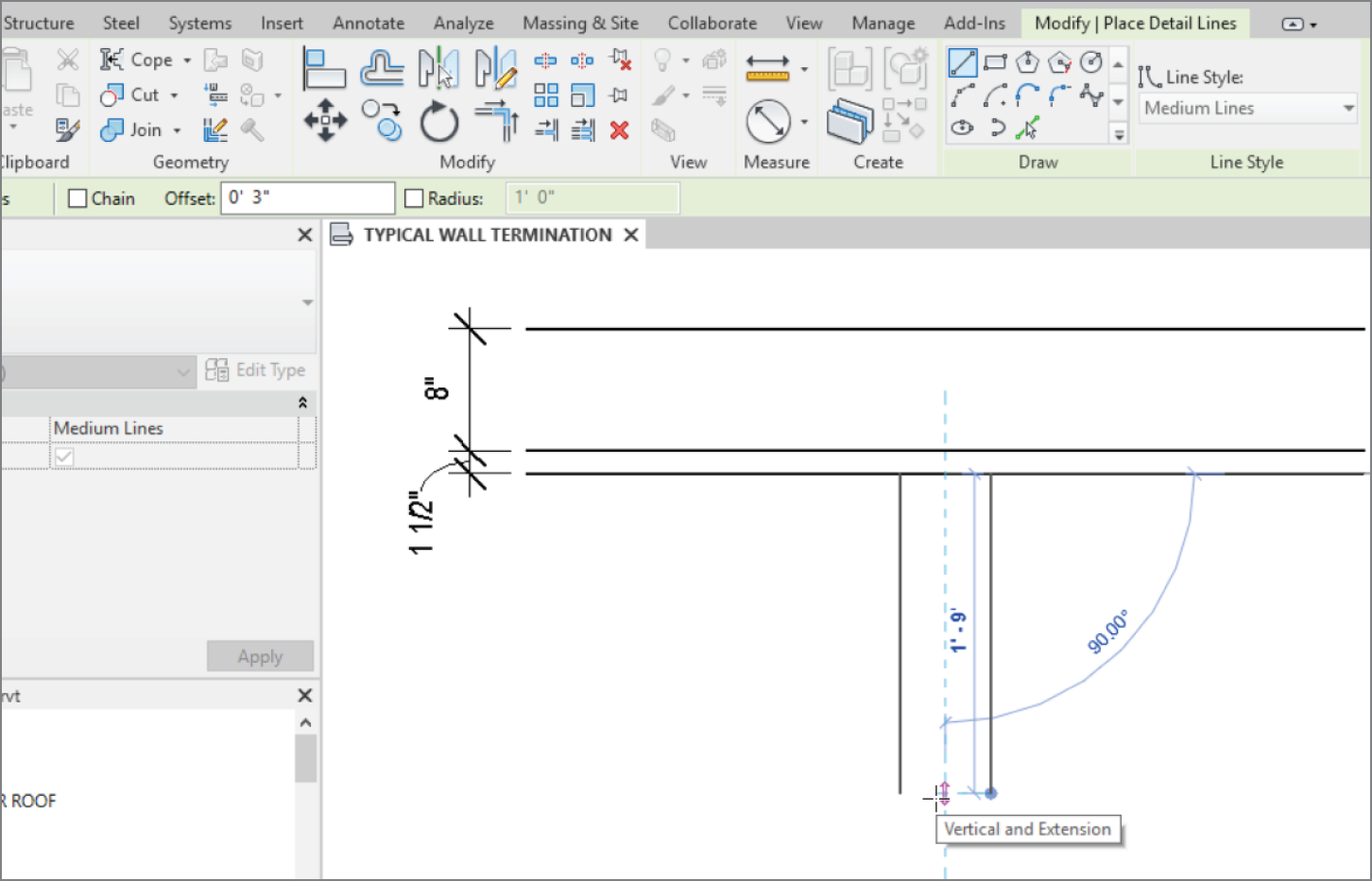
FIGURE 11.43 By setting an offset of 3″ (75 mm), you can draw two lines using a common centerline.
- Move your cursor down the view, but this time tap the spacebar to flip the line to the other direction (see Figure 11.44).
- Draw another line of the same length (again, see Figure 11.44).
- Click Modify.
- Compare your lines with the lines in Figure 11.44.
- Click the Trim/Extend To Corner button on the Modify tab, as shown in Figure 11.45.
- Trim the edges of the top of the wall (see Figure 11.45).
The next step is to add the track to the bottom of the floor. You'll do this by creating three wide lines. The trick is to do a good amount of offsetting. If you want to explore and try the procedure on your own, look ahead to Figure 11.46 and try to match it dimensionally. Remember, you're using wide lines for the track.
If you would rather have guidelines, follow these steps:
- On the Annotate tab, click the Detail Line button.
- In the Properties dialog, click Wide Lines.

FIGURE 11.44 The detail up to this point
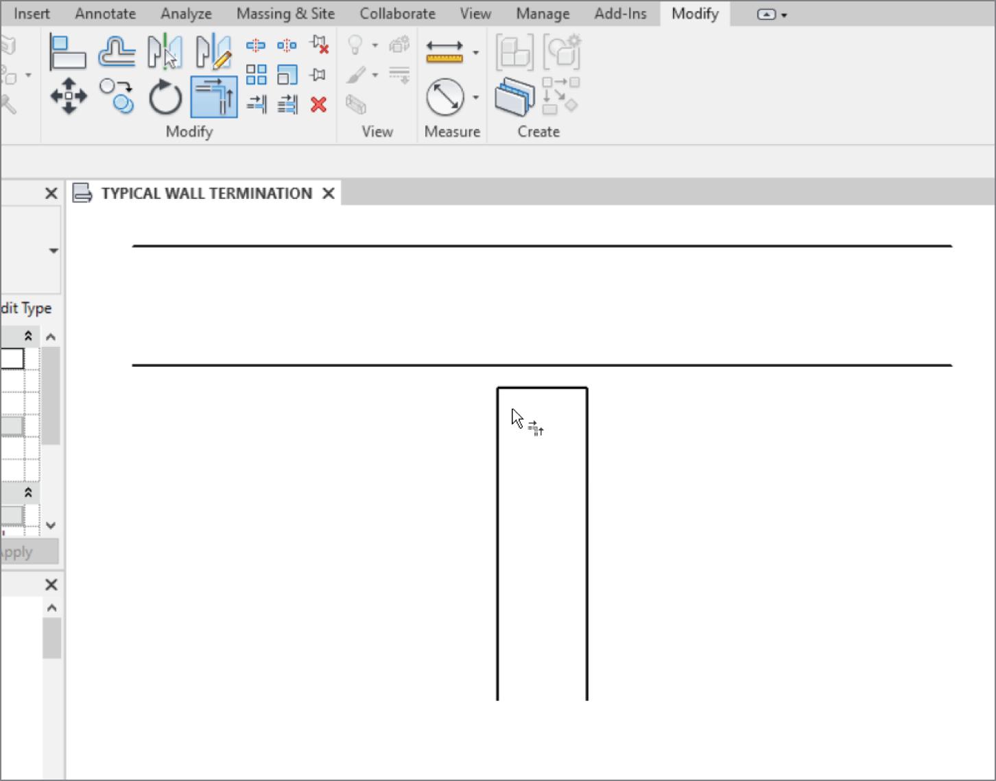
FIGURE 11.45 Trimming the corners
- In the Draw panel, click the Pick Lines button.
- On the Options bar, set Offset to 3/8″ (9 mm).
- Offset the bottom of the floor down 3/8″ (9 mm).
- With the Detail Line command still running, set Offset to 3/8″ (9 mm).
- Offset the left and the right lines, as shown in Figure 11.46.
- Offset the bottom of the “floor” down 3″ (75 mm).
- Trim the bottoms of the thick vertical lines to the 3″ (75 mm) horizontal line, as shown in Figure 11.46.
- Trim the top horizontal line to the new vertical lines.
- Delete the 3″ (75 mm) horizontal line. Your detail should now look like Figure 11.46.

FIGURE 11.46 The top track is now in place.
It's time to add the gypsum to both sides of the wall. By using the same method as you did before, you'll use thin lines to denote two layers of 5/8″ (15 mm) gypsum on both sides of the stud. If you're ready to complete this task on your own, go ahead. (Remember, you're adding two layers of 5/8″ [15 mm] gypsum to both sides of the wall, and you're using thin lines to denote this.)
If you would rather have some guidelines with which to practice, let's step through the procedure:
- On the Annotate tab, click the Detail Line button.
- Select Thin Lines in the Properties dialog.
- In the Draw panel, click the Pick Lines icon, as shown in Figure 11.47.
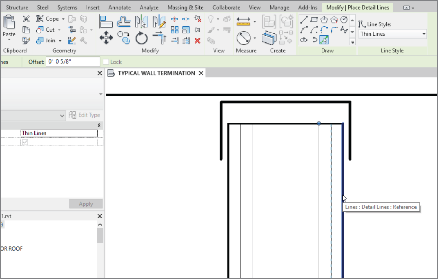
FIGURE 11.47 Adding the lines for the gypsum
- Type 5/8″ (15 mm) in the Offset field.
- Offset two lines in from the right and the left (see Figure 11.60).
Look at this: the steps are getting shorter. You used only the Detail Line command but have successfully offset every line you needed without leaving the command that you were running at the time. Who says you can't draft in Revit?
The next procedure involves adding a filled region to the “floor.” Although you don't want to be too specific about what you're calling out, you still need some contrasting hatch.
- On the Annotate tab, click the Region ➣ Filled Region button.
- In the Line Style panel, select <Invisible Lines>, as shown in Figure 11.48. On the Options bar, pick Chain.
Or, if you would like to venture out on your own, try to duplicate Figure 11.49. You'll need to add a filled region using diagonal lines. If you would rather follow the procedure, let's get started:
- Draw a boundary (see Figure 11.48), and press Esc.

FIGURE 11.48 Draw the filled region with invisible lines.
- In the Properties dialog, click the Edit Type button.
- Click Duplicate.
- Call the new region ROOF.
- Change Fill Pattern to Diagonal Up‐Small [Drafting].
- Click OK.
- Click Finish Edit Mode in the Mode panel. Your pattern should look like Figure 11.49. (Remember, the loop must be completely closed, with no gaps or overlaps.)
This detail is looking good—so good that it would be nice to never have to draw it again. Let's proceed with creating a special group that you can drag onto another view.
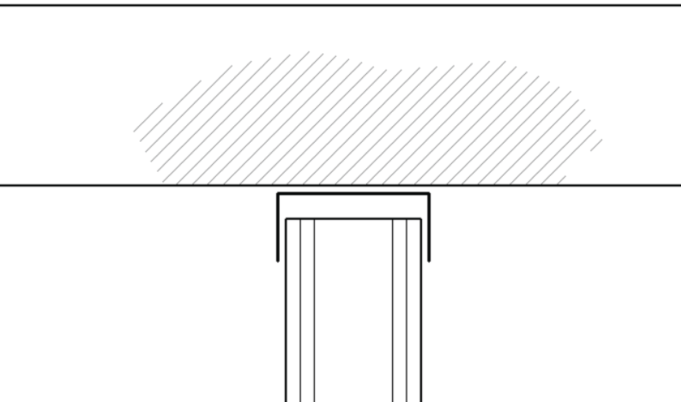
FIGURE 11.49 The detail with the hatching included
Creating a Detail Group
Groups can be extremely advantageous to the drafting process. Although I mentioned earlier that details and drafting views aren't linked to the model, you can still provide some global control within the details themselves by creating a group. This will give you further control over every instance of this specific detail in the entire model.
The objective of the following procedure is to create a new group and add it to another view:
- Select everything in the view by picking a window.
- On the Modify | Multi‐Select tab in the Create panel, click the Create Group button, as shown in Figure 11.50.
- In the Create Detail Group dialog, call the new group Typical Slip Track. Click OK.
- The group has been created. You see an icon similar to the UCS icon in AutoCAD; this is your origin. Pick the middle grip, and drag it to the left corner of the track (where it meets the floor), as shown in Figure 11.51.
- Save the model.
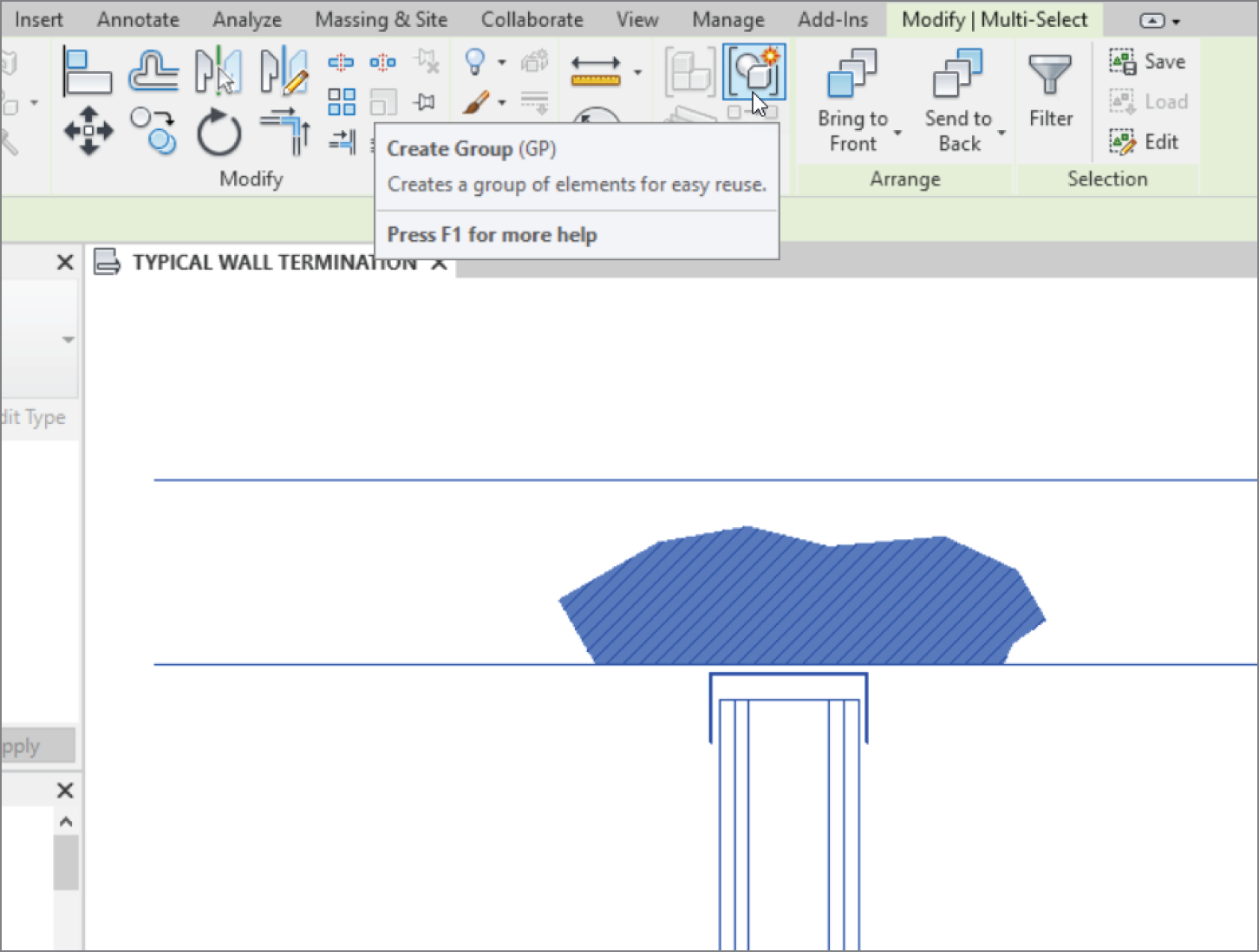
FIGURE 11.50 The Create Group button in the Create panel
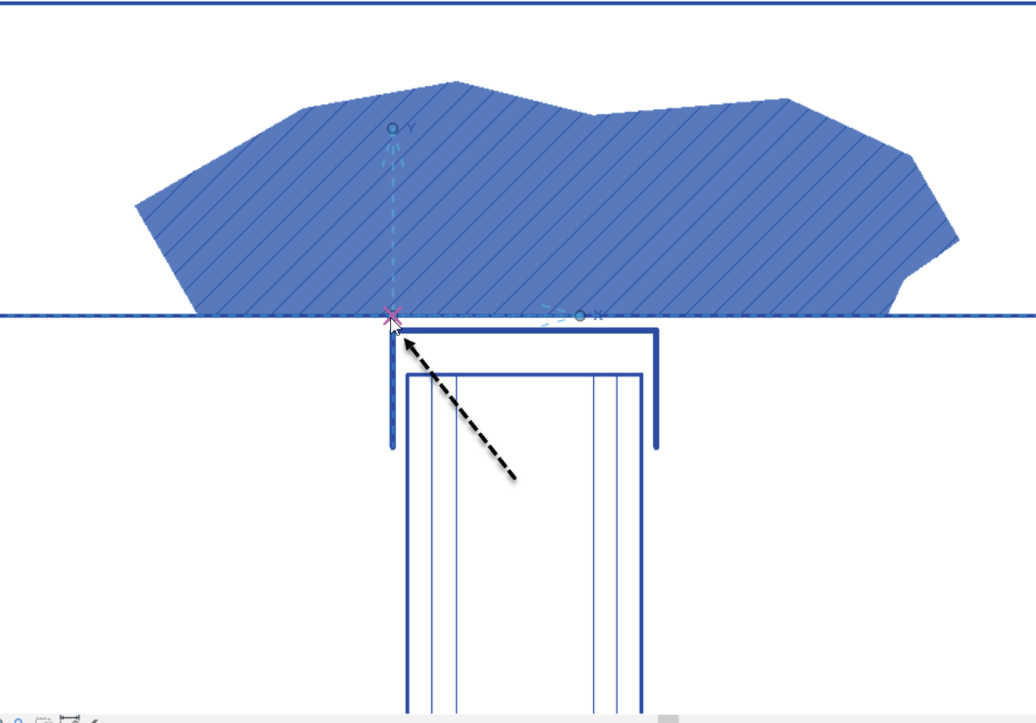
FIGURE 11.51 Move the origin to the location shown here.
With the group created, let's add it to another view. Because not every view shows exactly the same thing, you can alter the group's instance to conform to the detail into which it's being placed.
The objective of this next procedure is to add the new detail group physically to the Roof Taper Section:
- In the Project Browser, find the Sections (Building Section) called Roof Taper Section, and open it.
- On the Annotate tab, click Detail Group ➣ Place Detail Group, as shown in Figure 11.52.

FIGURE 11.52 Choose Place Detail Group.
- Move your cursor over the underside of the roof. You get a snap; this is the origin point of the detail.
- Pick a point along the bottom of the roof, similar to what is shown in Figure 11.53.
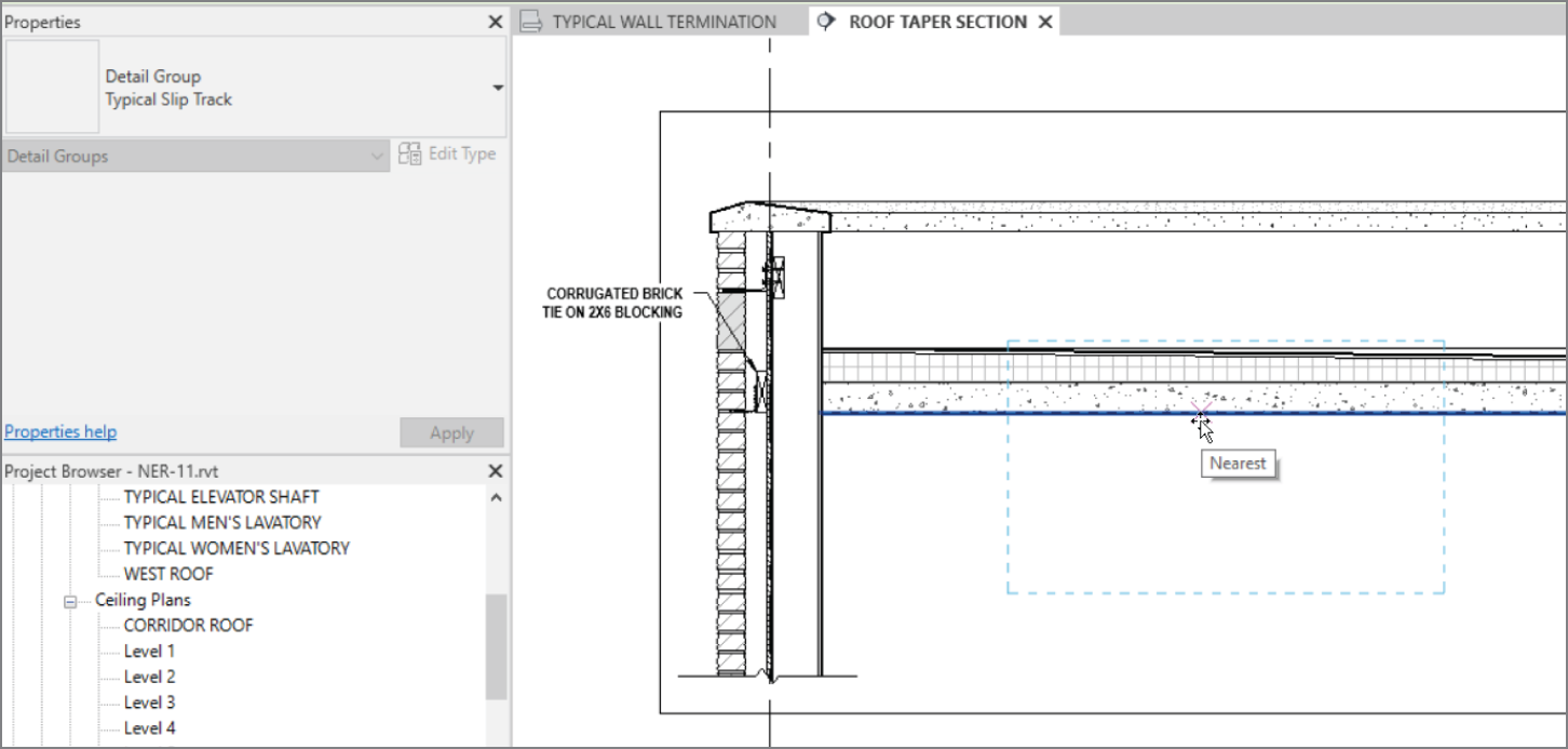
FIGURE 11.53 Picking a point along the bottom of the roof to place the group
- When the group is placed, press Esc.
The next step is to remove some of the extraneous hatch and lines. You can do this within a group, but you must be careful not to edit the group in a way that affects all other instances:
- Hover your cursor over the bottom line of the filled region, as shown in Figure 11.54.
- Press the Tab key. This allows you to select the filled region.
- Pick the region (see Figure 11.54).
- A small, blue group icon appears. When you hover your cursor over it, it says that you can exclude this member from the group. This is what you want to do, so click the button.

FIGURE 11.54 Excluding an element from the group
- Save the model. Your detail should now look like Figure 11.55.
Now you'll open the original group and make modifications to it to see how each insertion of a group is influenced. This is where the advantage of using groups in a model comes into play. When the modifications are completed, the other groups will be updated:
- In the Project Browser, find the Typical Wall Termination view under Drafting Views (Detail), and open it.

FIGURE 11.55 The slip track without the filled region
- Select the group.
- On the Modify | Detail Groups tab, click Edit Group.
- In the Detail panel of the Annotate tab, click the Insulation button, as shown in Figure 11.56.
- Place the insulation starting at the midpoint of the top of the stud, and terminate the insulation at the bottom of the stud, as shown in Figure 11.56. You're lucky the width fits perfectly. If it didn't, you could change the width on the Options bar.
- Click the Finish button on the Edit Group toolbar, as shown in Figure 11.57.
- Open the Roof Taper Section, and observe that the insulation has been added.
You're starting to understand detailing pretty well. There are two issues left to discuss. First, it would be nice to reference these details from the plan, even knowing that they aren't physically tied into the model. Second, you need to know how to import CAD into a detail.

FIGURE 11.56 Adding insulation to the group
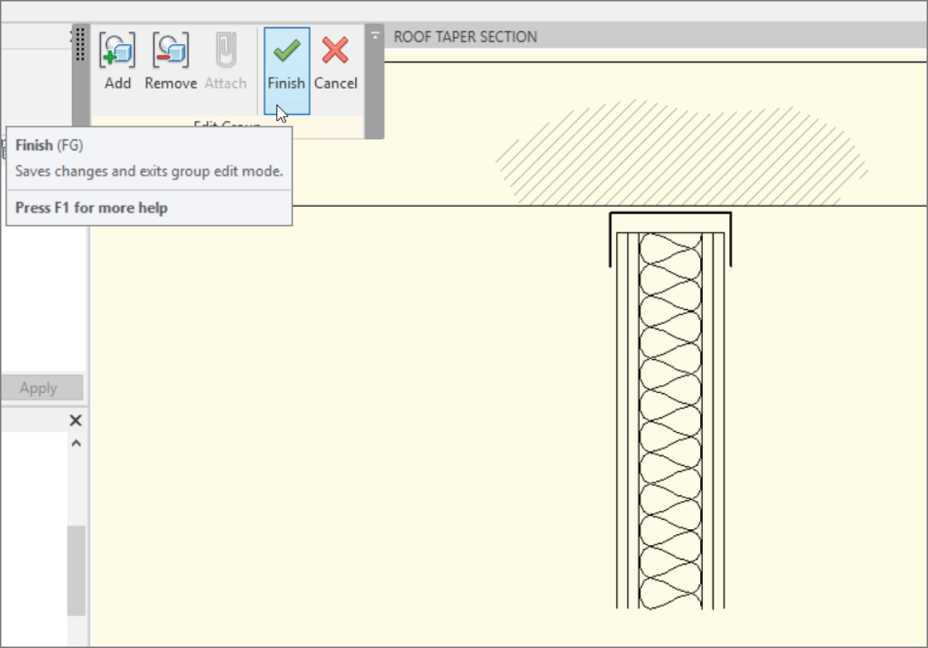
FIGURE 11.57 The Finish button on the Edit Group toolbar
Adding a Section to Another View
You already know how to add a section marker in a plan. What you may not know is how to tell Revit that you would rather specify the reference.
In this procedure, you'll go to the Level 1 ceiling plan and add a section pointing to your drafting view:
- In the Project Browser, open the Level 1 floor plan.
- Zoom in on the area of the east wing shown in Figure 11.58.
- On the View tab, click the Section button. Pick Detail in the Type Selector.
- Before you place the section, click the Reference Other View button on the Options bar.
- In the menu to the right of the Reference Other View label, expand the drop‐down and select Drafting View: TYPICAL WALL TERMINATION.
- Place the section into the model (see Figure 11.58).
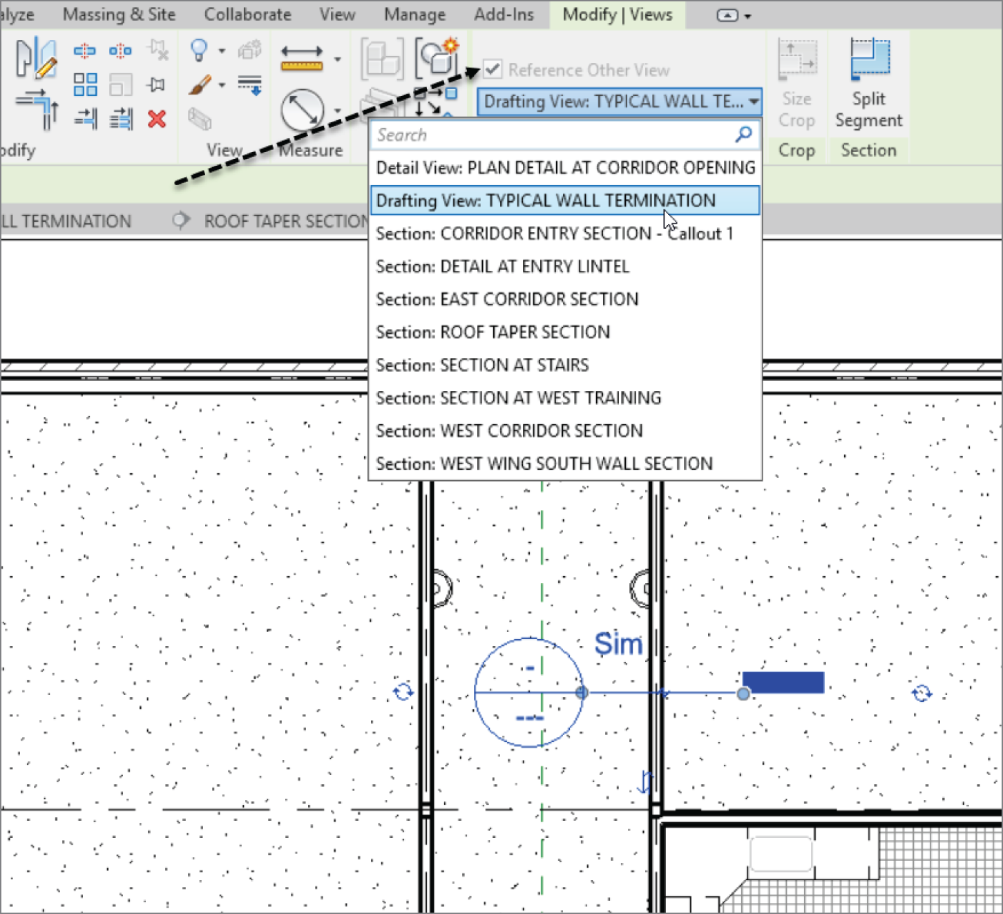
FIGURE 11.58 Choosing the correct options while placing the section
- Press Esc.
- Double‐click the section marker that you placed in the model. Doing so opens your drafting view.
- Save the model.
Creating a drafting view is behind you. Now it's time to look at our old friend CAD. (Some may say that the new meaning of the acronym is Ctrl+Alt+Delete.) Regardless of the existing sentiment toward CAD, it did get us this far. And we still need it—more so in the drafting capacity. Yes, you can import CAD files into a detail.
Importing AutoCAD Files into a Drafting View
I'll go out on a limb and venture to guess that you have a handful of CAD details that you use on a daily basis. The question always is, “What do I do with this pile of details I spent years and thousands of dollars to create?” Well, you can still use them.
The objective of the next procedure is to create a new drafting view and import an AutoCAD detail. If you would like, you can attempt to import your own detail, or you can use the file provided. Just go to the book's web page at www.wiley.com/go/revit2020ner. Browse to the Chapter 11 folder, and find the base cabinet.dwg file. You can then place it on your system for later retrieval.
Follow along:
- In the View tab, click the Drafting View button.
- In the next dialog, name the new view TYPICAL BASE CABINET.
- Set Scale to 1 1/2″ = 1′–0″, and then click OK.
- On the Insert tab, click the Import CAD button.
- Browse to the location where you placed your CAD file.
- Select the file, but don't click Open yet.
- At the bottom of the Import dialog, set Colors to Black And White.
- Set Layers/Levels: to Visible.
- Set Import Units to Auto‐Detect.
- Set Positioning to Auto ‐ Center To Center.
- Click Open.
- Type ZA. The detail should now be in full view.
- Select the detail.
- On the Modify | Base cabinet.dwg tab, click Explode ➣ Full Explode.
- Select one of the filled regions.
- In the Properties dialog, click Edit Type.
- Change Fill Pattern to Sand ‐ Dense, and select the Drafting radio button.
- Click OK.
- Click OK one more time to get back to the model.
- Make sure your cabinet is hatched properly.
- Save the model.
Up to this point, you've been using detail lines for your drafting. The one issue is that detail lines are visible only in the specific view in which you're working. Suppose you wanted linework to show up both in plan/elevation and in a 3D view. In this situation, you should use the actual Lines tool.
Adding 2D and 3D Lines to the Model
Just because you're drafting, that doesn't mean you can't create lines in all views, such as in a 3D view in a 3D function. Revit has a tool that is simply called Lines, and you use it to project lines into multiple views. You apply the Lines tool just like a detail line—only it behaves the same as a Revit 3D family in that you can see it in every view (unless you turn it off).
In this procedure, you'll add detail lines to the west sloping roof. They're nothing fancy, but you'll quickly get the idea of how to use this feature:
- In the Project Browser, find the West Roof floor plan and open it.
- On the Architecture tab, click the Set button in the Work Plane panel, as shown in Figure 11.59.
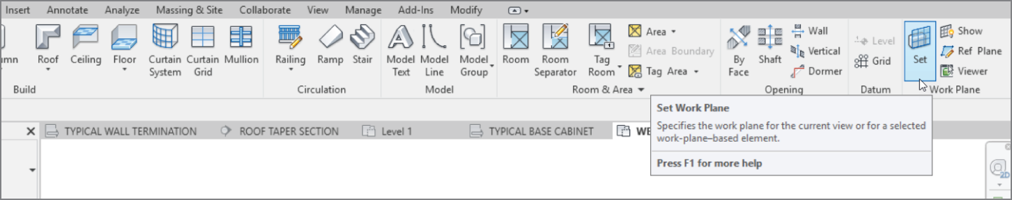
FIGURE 11.59 The Set button in the Work Plane panel of the Architecture tab
- In the Work Plane dialog, select the Pick A Plane radio button.
- Click OK.
- Pick the roof, as shown in Figure 11.60.
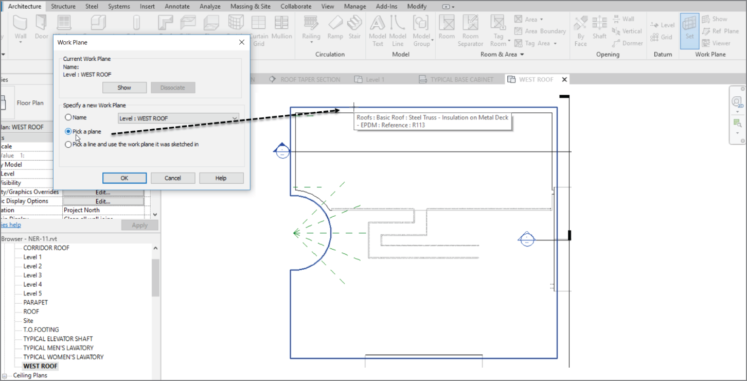
FIGURE 11.60 Picking the roof. Your work plane is now set to slope with the roof. Anything you draw will be on this sloping plane.
- In the Model panel of the Architecture tab, click the Model Line button.
- In the Line Style menu, select Medium Lines, as shown in Figure 11.61.
- In the Draw panel, click the Start‐End‐Radius Arc button, as shown in Figure 11.61.
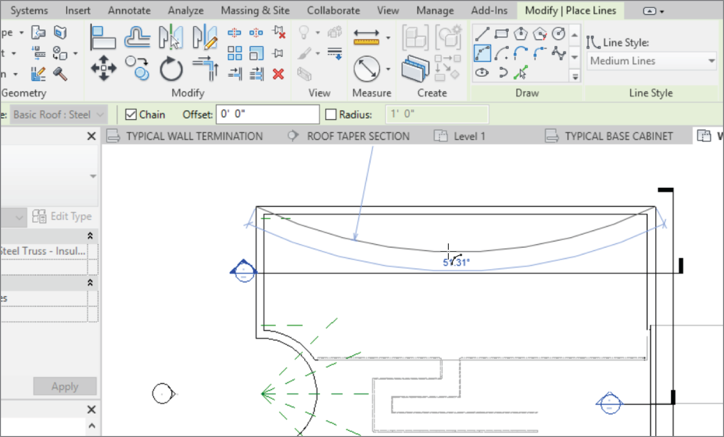
FIGURE 11.61 Drawing an 80′–0″ (24 m) radius arc
- Draw an arc from the two endpoints shown in Figure 11.61. Make the radius 80′–0″ (24000 mm). Simply enter the numbers on the keyboard and press Enter, and they will fill in the radius field. Click Modify.
- Go to an exterior 3D view. You can still see the arc.
- Save the model.
It's a good idea to keep this feature in mind. This drafting tool will become useful when it comes to sketching in 3D. You'll encounter many situations in which you'll use this little nugget.
Are You Experienced?
Now you can…
- modify and add line weights to be used in both the 3D and 2D environments
- add linework in a drafting view as well as a 2D and a 3D view
- create both masking regions and filled regions to provide hatching to a model
- mask an area so that you can draft over it
- add detail components to the model and create repeating details
- modify detail families to suit your needs
- create a group to be used in multiple drafting views, change the group, and update each copy in each view
- create a new drafting view to draft from scratch and import a CAD file into a drafting view