
CHAPTER 4
Working with the Autodesk Revit Tools
You can get only so far when allowing a computer application to place architectural components into a model. At some point, the application needs to be flexible enough to enable users to employ their own sets of drafting and modifying tools, thus providing architects and designers with the freedom to create their own architecture and construction procedures. The Autodesk® Revit® program does provide the basic modify and edit commands, which are quite common in other drafting applications such as Autodesk® AutoCAD® software and MicroStation, but Revit does this with a little more flair and some differences in procedure as compared to a 2D drafting application.
This chapter covers the following topics:
- The basic edit commands
- The Array command
- The Mirror command
- The Align tool
- The Split Element command
- The Trim command
- The Offset command
- Copy/Paste
- Creating the plans
The Basic Edit Commands
In this chapter, you'll learn how to use the geometry you've already placed in the model to build an actual working plan. As you manipulate the plan, all of the other views you made in Chapter 3, “Creating Views,” will reflect those changes. You'll start with the edit commands.
You aren't going to get very far in Revit without knowing the edit commands. Up to this point, we have been avoiding the edit commands with a few exceptions. There will be some overlap in some of the chapters, because many aspects of Revit span multiple topics.
The basic commands covered in this section are Move, Copy, and Rotate. Then, in the following sections, you'll move on to Array, Mirror, Align, Split Element, Offset, Copy/Paste, and Trim. Each command is as important as the next at this stage of the game. Some are obvious, whereas others can take some practice to master.
The first command, Move, is one you'll recognize from previous chapters. Move is probably the most heavily used command in Revit.
The Move Command
The Move command is generally used to create a copy of an item while deleting the original item.
Begin by finding the model you're using to follow along. If you haven't completed the previous chapter procedures, open the file called NER‐4.rvt found at the book's website, www.wiley.com/go/revit2020ner. Go to the Chapter 4 folder to find the file.
To use the Move command, perform the following steps:
- Go to Level 1 under the Floor Plans category in the Project Browser.
- Zoom in on the west wing.
- Select the south wall of the bump out at the south side of the west wing, as shown in Figure 4.1.

FIGURE 4.1 Select the wall to be moved. The Move button now appears on the Ribbon.
- On the Modify | Walls tab is the Move button (see Figure 4.1); click it.
- Now that the Move command is running, you see some choices on the Options bar:
Constrain If you select Constrain, you can move only at 0, 90, 180, or 270 degrees.
Disjoin If you select Disjoin, then when you move the wall, any walls that are joined to it won't be affected by the move. The wall will lose its join.
- To start moving the item, you must first pick a base point for the command. Pick a point somewhere toward the middle of the wall, as shown in Figure 4.2.
- After you pick this point, move your cursor straight up. You see a blue dimension. At this point, you have two choices: you can eyeball the increment, or you can type the increment you want (see Figure 4.2).
- Type in the value 2′–6″ (750 mm), and press Enter. The wall moves 2′–6″ (750 mm). Notice that the adjacent walls move with it. In Revit, there is no stretch command.

FIGURE 4.2 Choices on the Options bar. The first point has been picked, and the wall is being moved up.
Now that Move is officially in the history books, it's time to move on to Move's close cousin: the Copy command.
The Copy Command
When you need to make duplicates of an item, Copy is your go‐to player. The Copy command works like the Move command, except that it leaves the initial item intact. You can also create multiple copies if necessary.
To start using the Copy command, do the following:
- Make sure you're still in Floor Plan Level 1.
- Zoom and pan so you're focused on the east wing, as shown in Figure 4.3.
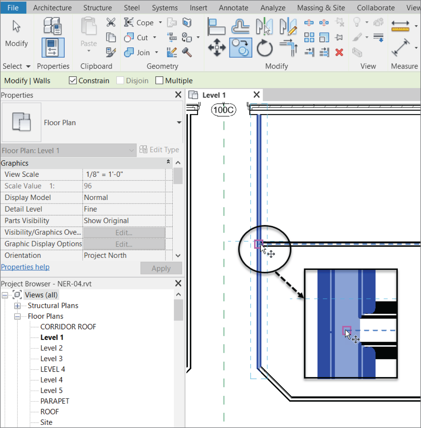
FIGURE 4.3 Creating a copy of the corridor wall
- Select the right corridor wall (see Figure 4.3).
- Click the Copy command on the Modify | Walls tab.
- On the Options bar, check the Constrain toggle.
- Zoom in on the wall close to the midpoint of the selected wall and the intersection of the horizontal wall that divides this portion of the building (see Figure 4.3).
- If you hover your cursor in the center of the wall (not near the actual finish faces, but the core of the wall), you'll see a blue dotted centerline indicating that you've found the center of the wall. (If you're having difficulty picking the item, change the detail level to Coarse.)
Also, if you move your cursor to the right a little, you can position it so that it picks up the horizontal wall's centerline. After you pick up the horizontal wall's centerline, the centerline for the vertical wall will disappear. This is fine.
When you see that you're snapped to the endpoint of the horizontal wall, pick the point (see Figure 4.3).
- Move to the right until you pick up the midpoint of the horizontal wall. When you do, pick that point. If the midpoint doesn't appear, type 22′–3″ (6675 mm) or type SM for Snap Mid.
- Select the horizontal wall and the wall you just added by using the Copy command.
- Type MM (don't hit Enter).
- By picking the reference plane along the center of the building, you mirror the two walls to the south side of the corridor, as shown in Figure 4.4. The ends of the walls don't meet. This is fine—you'll modify these walls with the Extend command in a moment.
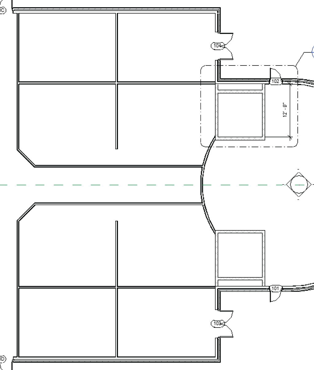
FIGURE 4.4 The two walls copied, segmenting the spaces north and south of the corridor
- Save the model.
The next step is to rotate an item. Although the Rotate command is a simple concept, Revit does have unique processes involved in this command.
The Rotate Command
The Rotate command enables you to change the polar orientation of an item or a set of items. This command may take a little practice to understand. The good thing, however, is that once you have experience with the Rotate command, you'll be better at other commands that share a similar process.
To use the Rotate command, do the following:
- Open the Level 1 floor plan.
- Zoom in on the radial portion of the west wing, as shown in Figure 4.5.
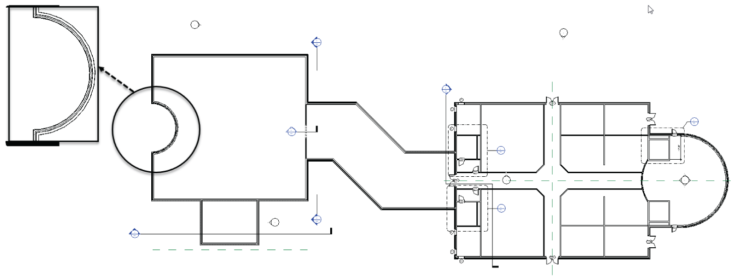
FIGURE 4.5 The radial portion of the west wing
- You're going to add a new reference plane and rotate it by 45°. To do so, click Ref Plane in the Work Plane panel in the Architecture tab (see Figure 4.6).

FIGURE 4.6 Creating a reference plane
- In the Draw panel, click the Line button (it should be “set current” by default).
- For the first point, pick the center point of the radial wall, as shown in Figure 4.7.
- For the second point, pick a point horizontally to the right, outside the radial wall (again, see Figure 4.7).
- Press Esc twice, or click Modify.
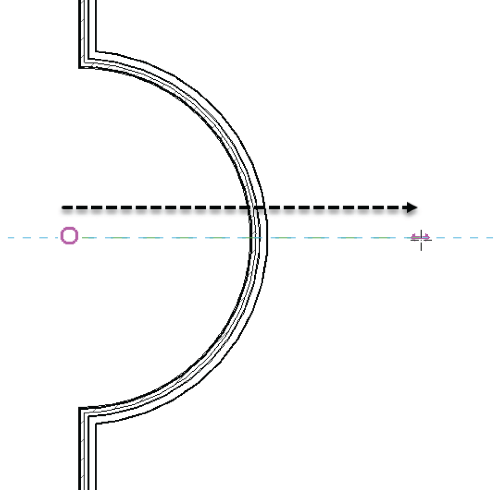
FIGURE 4.7 Adding a horizontal reference plane
Now that you've added the reference plane, you can rotate it into place. (Yes, you could have just drawn it at a 45° angle, but you're practicing the Rotate command here.) Follow these steps:
- Select the reference plane you just drew.
- On the Modify | Reference Planes tab, click the Rotate button, as shown in Figure 4.8.
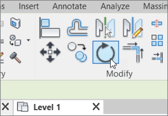
FIGURE 4.8 The Rotate command is active for the specific item you've selected.
- After you start the Rotate command, look back at the reference plane. Notice the blue dot in the middle of your line. Revit always calculates the center of an object (or group of objects) for the rotate point (see Figure 4.9).

FIGURE 4.9 Relocate the origin point for the rotation.
- On the Options bar, click the Place button for Center of rotation, and select the end point of the reference plane. A temporary rotate icon appears, indicating that you can now move the blue dot (see Figure 4.9).
- With the rotate origin in the correct location, it's rotate time! If you swivel your cursor around the reference plane, a line forms from the rotate origin to your cursor. This indicates that the origin is established. Now you need to pick two points. The first point you pick must be in line with the object you're rotating. In this case, pick a point at the right endpoint of the reference plane, as shown in Figure 4.10.
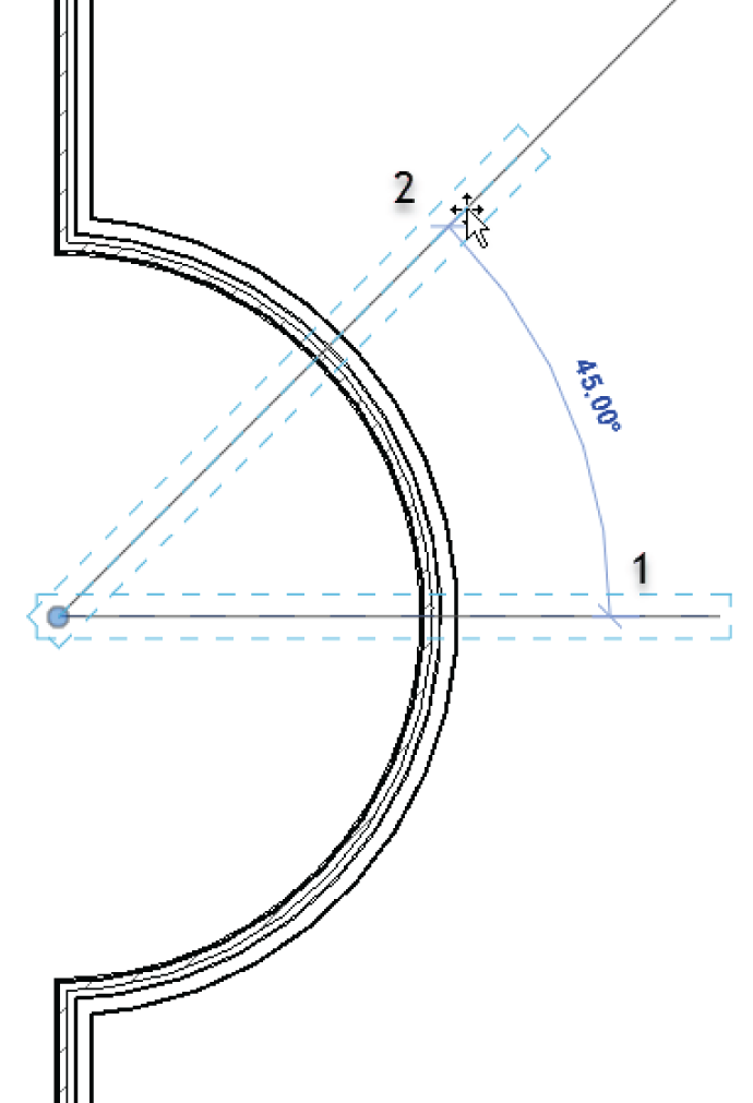
FIGURE 4.10 To rotate an item, you must specify two points.
- When you move your cursor up, you see an angular dimension. When that angular dimension gets to 45°, pick the second point (see Figure 4.10).
- Press Esc.
As you're well aware, you'll use the Rotate command quite frequently. Now that you have some experience with the Rotate command and know how Revit wants you to move the pivot point, the next command—Array—will be easy for you to grasp.
The Array Command
When you need to create multiple duplicates of an item or a group of items, the Array command is the logical choice. The Array command in Revit functions in a fashion similar to the Rotate command. The similarities of the Array command also extend to the Array command in AutoCAD. You have two basic choices:
- Radial, which enables you to array an item around a circle or an arc
- Linear, which enables you to array an item in a straight line or at an angle
Let's look at the radial array first.
Radial Array
A radial array is based on a radius. If you need items to be arrayed in a circular manner, the radial array is your best choice. Again, after you start the Array command, don't ignore the Options bar. It will guide you through most of the command.
To start using a radial array, follow these steps:
- Select the 45° reference plane.
- On the Modify | Reference Planes tab, click the Array button, as shown in Figure 4.11.
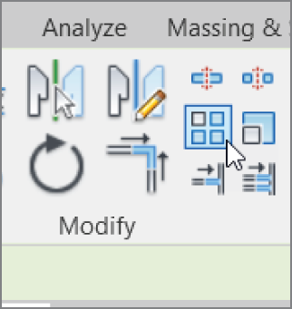
FIGURE 4.11 Select the item to be arrayed first, and then click the Array button on the Modify | Reference Planes tab.
- With the Array command active, some choices become available on the Options bar, as shown in Figure 4.12. For this procedure, click the Radial button.
- Select the Group And Associate check box.
- Set Number to 4.
- Click the Move To: Last button.
- With the options set, focus your attention on the object being arrayed. Notice the familiar rotate icon.
- On the Options bar, click the Place button. It's located next to the Origin label, as shown in Figure 4.12.
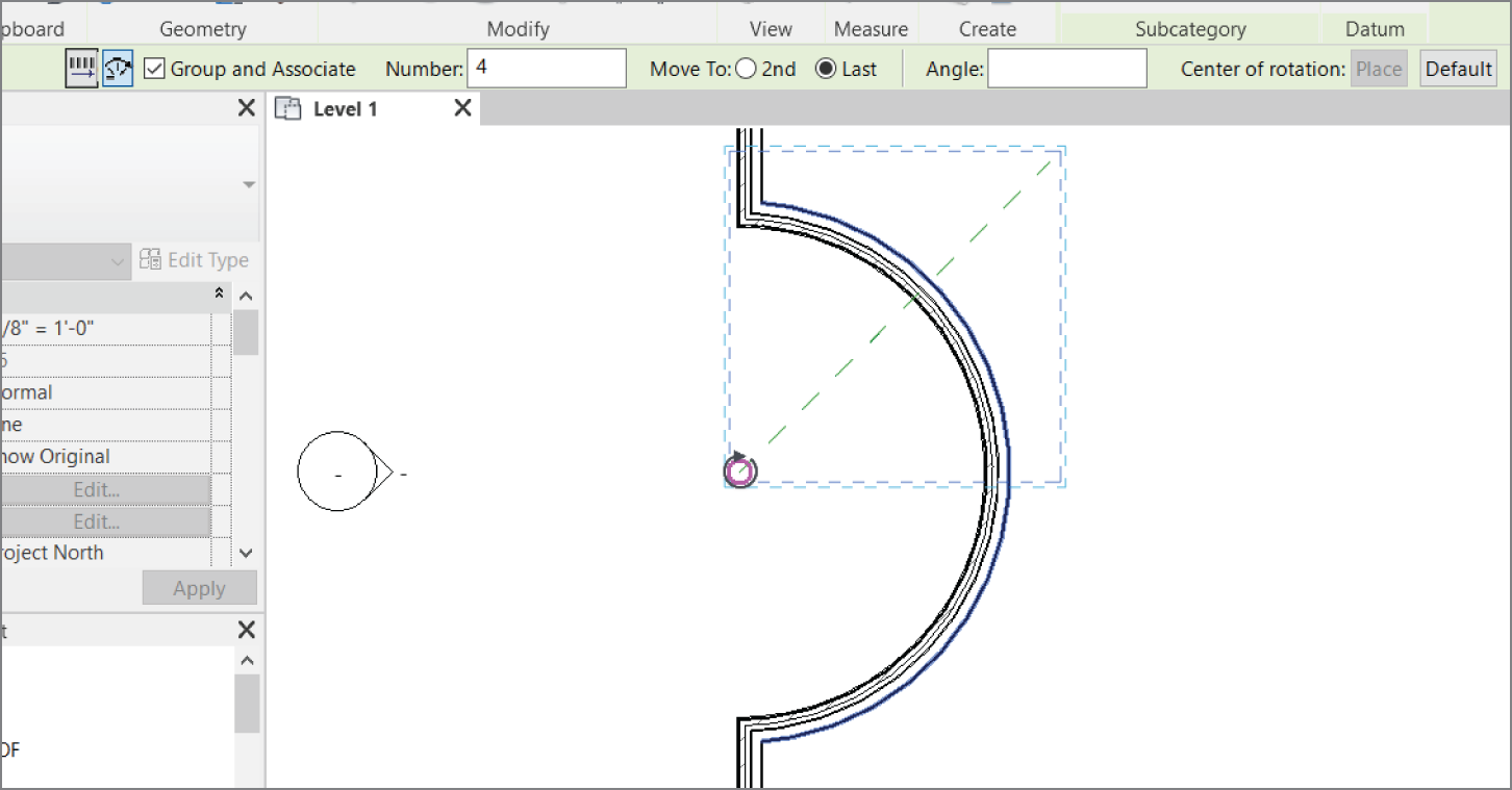
FIGURE 4.12 Setting the options for the Radial array and selecting the center point
- Click the center/endpoint of the reference plane (see Figure 4.13).
- With the pivot point in place, specify two points for the array. The first point will be a point along the angle of the item being arrayed. The second point will be a point along the angle on which you want to end.
- Pick the endpoint of the reference plane you're arraying.
- Move your cursor down until you see 90°. Then pick the second point (see Figure 4.13).
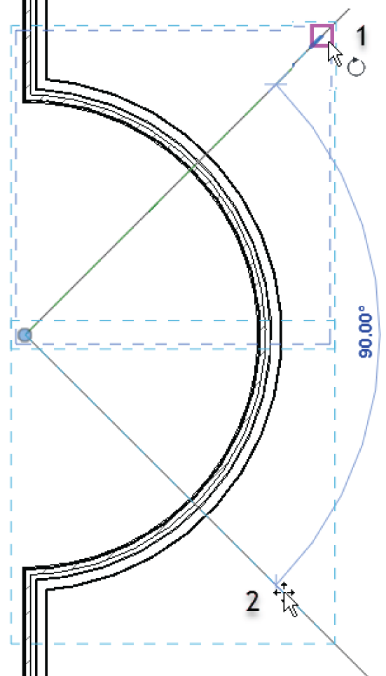
FIGURE 4.13 Specifying the two points for the radial array
- Pick (left‐click) off into another part of the view. This establishes the array. You should have four reference planes at this point, similar to Figure 4.14.
- Pick (left‐click) one of the reference planes. You see a large, dashed box surrounding the reference plane and a temporary arc dimension with a blue number 4 at the quadrant. It may be obscured by the arc, as it is in Figure 4.14, but it's there nonetheless.
- Click the number 4.
- Change the count to 5. Press Enter, or click outside the array count field to set the change.
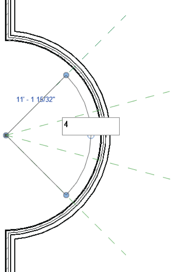
FIGURE 4.14 After the array is created, select one of the arrayed members. Notice that you can change the count.
Getting the hang of radial arrays may take a few projects. The next array type, the linear array, follows the same concept as the radial array, but it's more straightforward. Yes, pun intended.
Linear Array
You may wish to create an array along a line, and you can do this in Revit. When you create a linear array, you enjoy the same flexibility that you have with a radial array.
The objective of this procedure is to create an array of windows along the north and south walls, on the west side of the building's west wing. To do this, you'll first need to establish two strong reference planes.
To learn how to use the Linear array command, follow along:
- Zoom in on the northwest section of the west wing, as shown in Figure 4.15.
- Add two reference planes. You'll use these reference planes to establish the ends of your window array. Go to the Ref Plane command on the Work Plane panel of the Architecture tab.
- On the Draw panel, keep the Line icon active and add an offset of 1′–6″ (450 mm)—Imperial users, remember that you can just type 1 6—on the Options bar.
- Select the upper‐left corner of the intersection of the walls as shown in Figure 4.15.
- Move your cursor to the right. Notice the reference plane is above the wall. We want it below the wall.
- Hit the spacebar. That will flip the reference plane down.
- Pick a spot 2 or 3 feet to the right. That will add your reference plane.

FIGURE 4.15 Creating the first reference plane; remember to hit the spacebar to flip the ref plane into the correct orientation.
- Hit Esc once.
- Zoom in on the intersection of the vertical wall and the radial wall as shown in Figure 4.16.
- Pick the outside corner.
- Hit the spacebar.
- Move your cursor to the right about 2 or 3 feet and pick a spot. Your two reference planes should resemble Figure 4.17.
- Press Esc a few times.
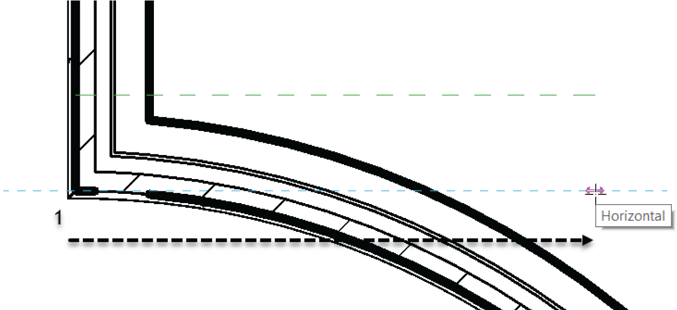
FIGURE 4.16 Creating the second reference plane; remember to hit the spacebar to flip the ref plane into the correct orientation.

FIGURE 4.17 The two reference planes are established.
Now you need to add a window based on the bottom reference plane. This window will then be arrayed up the wall to meet the northern reference plane. Here are the steps:
- On the Architecture tab, click the Window button.
- Change Element Type to Fixed: 24″ × 72″ (610 mm × 1829 mm).
- Place the window approximately where it's shown in Figure 4.18. You have to move the window in alignment with the reference plane.
- Press the Esc key.
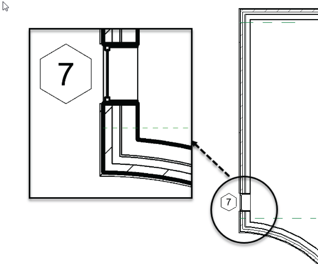
FIGURE 4.18 Adding the window to be arrayed
- Select the window.
- On the Modify | Windows tab, click the Move button.
- Move the window from the bottom, outside corner down to the reference plane, as shown in Figure 4.19.
- Press Esc.
- Zoom out until you can see the entire wall.
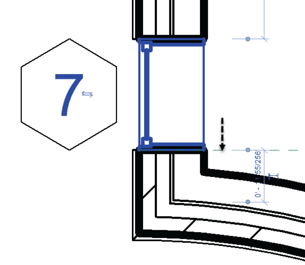
FIGURE 4.19 Moving the window into position
- Select the window you just inserted into the wall.
- On the Modify | Windows tab, click the Array button.
- On the Options bar, select Linear, as shown in Figure 4.20.
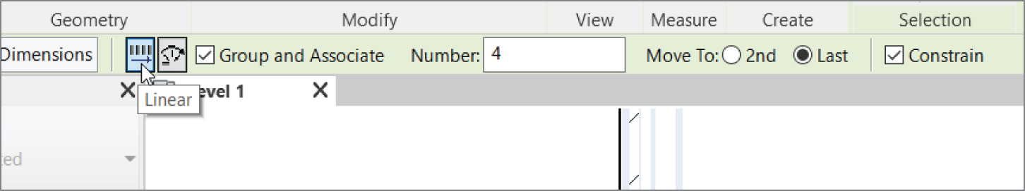
FIGURE 4.20 Choosing the linear array options
- Select the Group And Associate check box (if it isn't already selected).
- For Number, enter 4.
- Select Move To: Last.
- Pick the top endpoint of the window.
- Move your cursor up the wall, and pick a point perpendicular to the top reference plane, as shown in Figure 4.21.
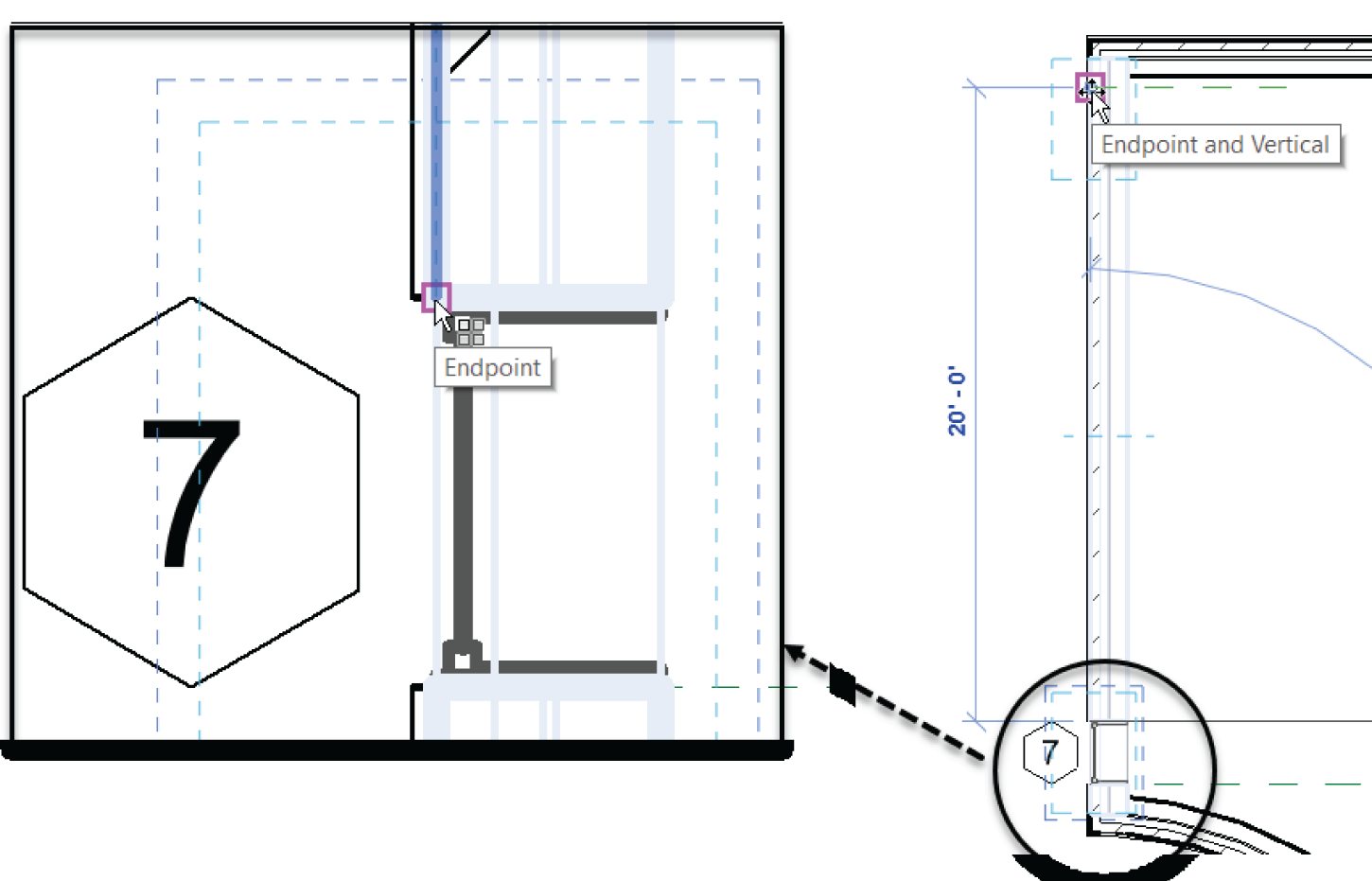
FIGURE 4.21 “Moving” the window to the top reference plane
- After you pick the second point, you'll have to wait a moment; then Revit evenly fills the void with the two additional windows. Revit also gives you the option of adding more windows. Enter a value of 5, and press Enter (see Figure 4.22).
With the array completed, it's time to duplicate your efforts on the other side of the radial portion of this wall. As in CAD, at this point you have a few choices. You can repeat the Array command, copy the items, or mirror the items.

FIGURE 4.22 Changing the number of items in the array. You can always come back to the arrayed group and change this value at any time.
The Mirror Command
The Mirror command works exactly as expected: it makes a copy of an object or a group of objects in the opposite orientation of the first item(s). The crucial point to remember is that you'll need to specify a mirror plane.
Although you simply couldn't avoid using this command in previous chapters, we need to address and explore the Mirror command officially. The most useful aspect of the Mirror command is that if reference planes already exist in the model, you can pick these planes to perform the mirror, as opposed to sketching a new plane around which to mirror.
The objective of the following example is to mirror the windows to the south side of the west wall:
- Zoom in on the windows you arrayed in the previous exercise.
- Hold down the Ctrl key and individually select all of the windows and tags as shown in Figure 4.23.
- Click the Filter button as shown in Figure 4.23 to ensure you didn't overselect.
- On the Modify tab, click the Mirror ‐ Pick Axis button, as shown in Figure 4.24.
- Position your cursor over the center reference plane that is part of the Radial array. When you pause, a tooltip indicates that you're about to select the reference plane. When you see this tooltip, select the reference plane, as shown in Figure 4.25.
- Zoom out to check the placement of the windows. Don't assume that everything went as planned. Your Level 1 floor plan should resemble Figure 4.26.
The two straight walls have windows, and it's time to array some windows within the radial portion. The problem is, when you insert a window along a radius, you can't snap it to the intersection of the reference plane and the wall. This is where the Align tool becomes critical.
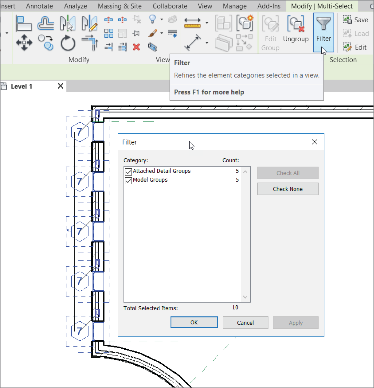
FIGURE 4.23 Selecting the items to be mirrored. Make sure you don't select the wall in which the windows reside.
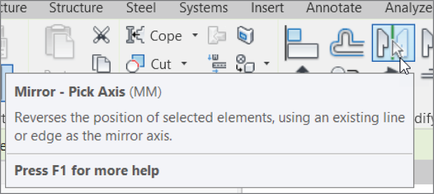
FIGURE 4.24 The Mirror buttons appear when you select an item.

FIGURE 4.25 The line you're going to pick is the reference plane shown here.
The Align Tool
You'll find yourself in situations where two items need to be aligned with each other. The Align command is a great tool for accomplishing this task. It's one of the most useful tools in Revit, and you'll use it extensively. Overuse of this command isn't possible! Because Align is a tool, you don't have to select an item first for this function to become available. You can select Align at any time.
To practice using the Align tool, follow along:
- Zoom in on the radial portion of the west wall, as shown in Figure 4.27.
- On the Architecture tab, click the Window button.
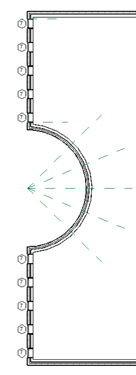
FIGURE 4.26 The finished west wall
- In the Type Selector, choose Fixed: 16″ × 72″ (406 mm × 1829 mm).
- Place the window in the radial wall in a location similar to that shown in Figure 4.27. Don't attempt to eyeball the center of the window with the reference plane. As a matter of fact, purposely misalign the window.
- On the Modify tab, click the Align button, as shown in Figure 4.28.
- The Align tool needs you to select two items. First, select the item you want to align to; pick the reference plane as shown in Figure 4.29.
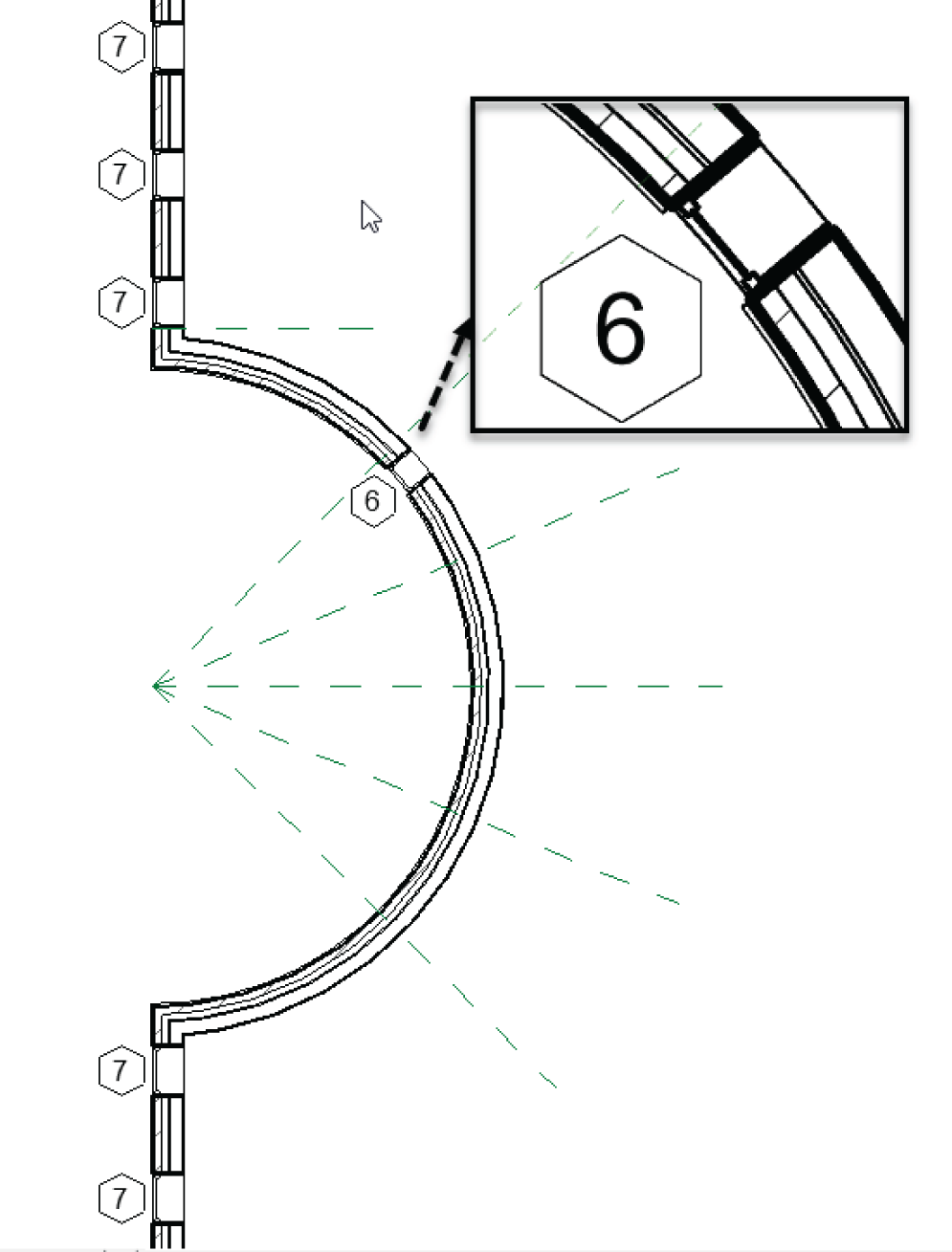
FIGURE 4.27 Place the window approximately in the area shown here.
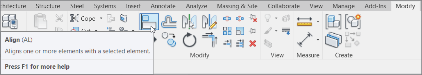
FIGURE 4.28 Click the Align button on the Modify | Place Window tab.
- Now you need to pick a point on the window: the centerline of the window. By looking at the window, you won't see this line. Hover your cursor over the middle of the window, and a centerline becomes highlighted. When you see this centerline, pick the window.
The window moves into alignment with the reference plane, as shown in Figure 4.30.
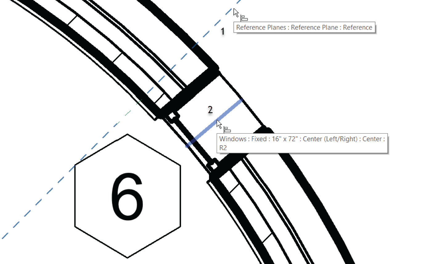
FIGURE 4.29 Choosing the items for alignment. Remember that you must first choose the item you want to align to.
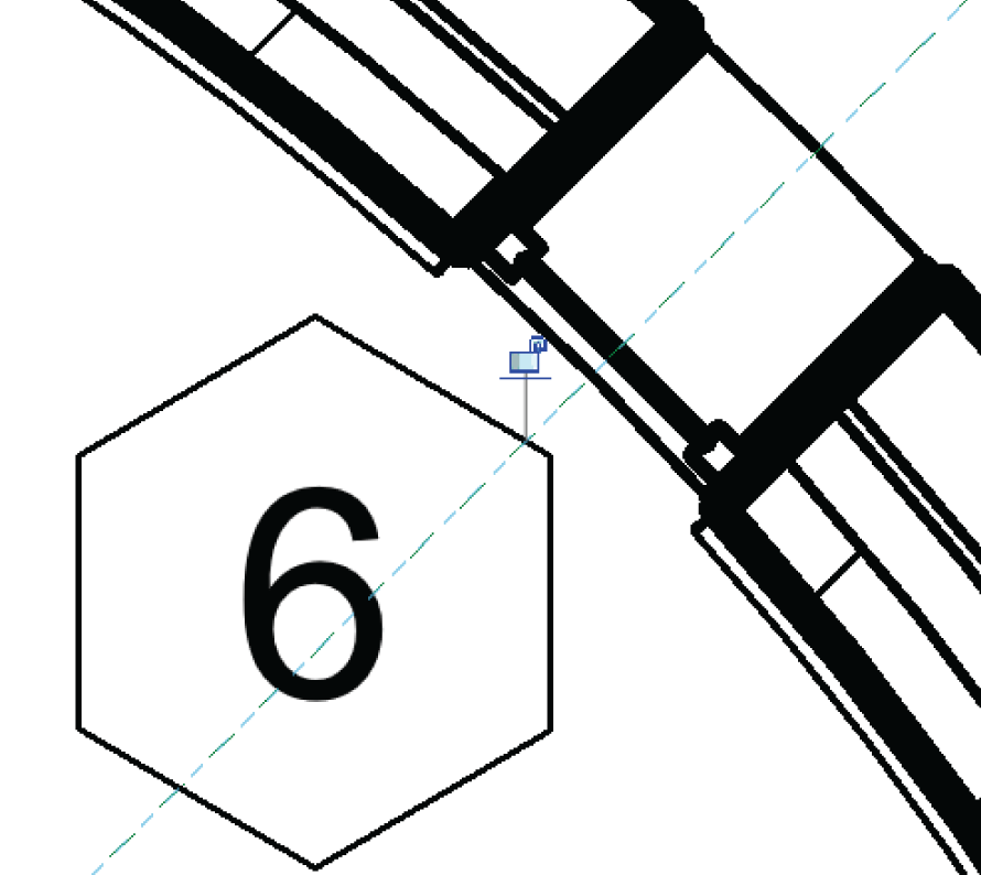
FIGURE 4.30 The window is now in alignment with the reference plane.
- Press Esc, and then select the window.
- Pick the Array button on the Modify | Windows tab.
- Create a radial array of the windows with a count of five (total). You remember how, right? The only thing I want you to do differently is to uncheck Group And Associate on the Options bar. See Figure 4.31.
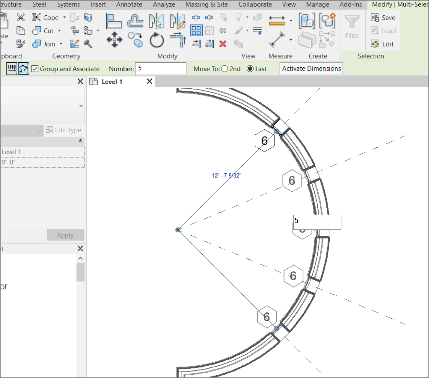
FIGURE 4.31 The window is now in alignment with the reference plane.
Let's practice more with the Align tool. It's one of the most important modify tools in the Revit arsenal, and I don't want to understate its usefulness. Follow along with these steps:
- Zoom into the end of the corridor in the east wing of the building, as shown in Figure 4.32.
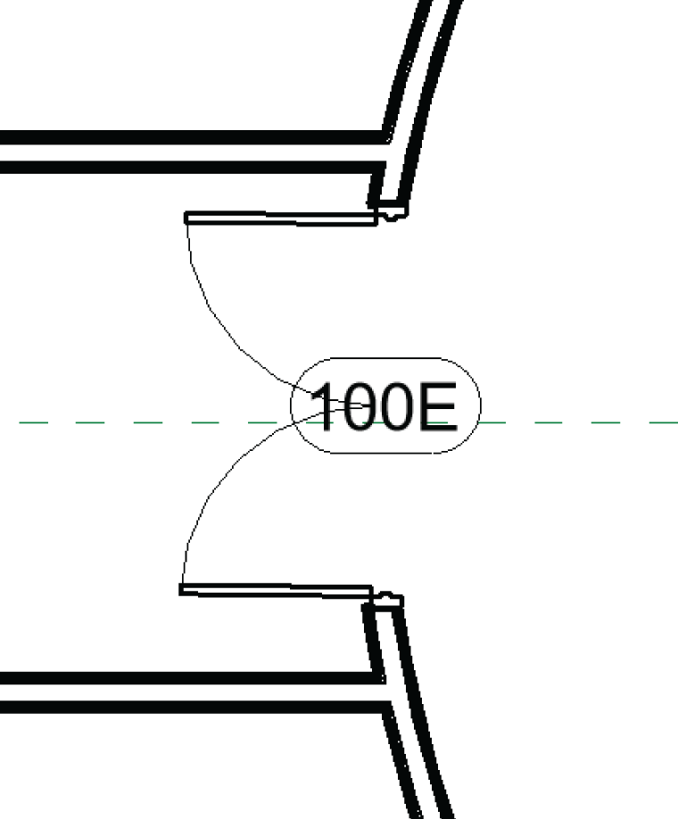
FIGURE 4.32 Adding a double door to the east wing corridor
- On the Architecture tab, click the Door button.
- Place a Double‐Passage‐Double‐Flush: 72″ × 84″ (1829 mm × 2133 mm) door in the radial corridor wall, as shown in Figure 4.32. As when you placed the window along the reference plane in the preceding procedure, don't try to eyeball the correct alignment; you want to misalign the door on purpose.
- Renumber the door 100A.
- On the Modify panel, click the Align button (or type AL).
- Pick the horizontal reference plane.
- Pick the centerline of the door. When the reference plane is aligned, pause for a moment without pressing Esc. You see a little blue padlock. If you can't see it, zoom out a little. You can use this function to lock the alignment.
You can physically lock the items together, allowing the two aligned items to move as one.
Locking an Alignment
After you've aligned the items, you'll notice that small, blue padlock icon I just mentioned. In Revit, you can lock items together using the Align tool. This is both good and bad. It's great in the sense that if the center reference plane moves for whatever reason, the door will also move. It's bad in the sense that if the door moves, the center reference plane will also move.
When you align an item and lock it, be sure this is what you want to do. It's simple: pick the padlock icon, as shown in Figure 4.33. You're now aligned and locked to the center reference plane.
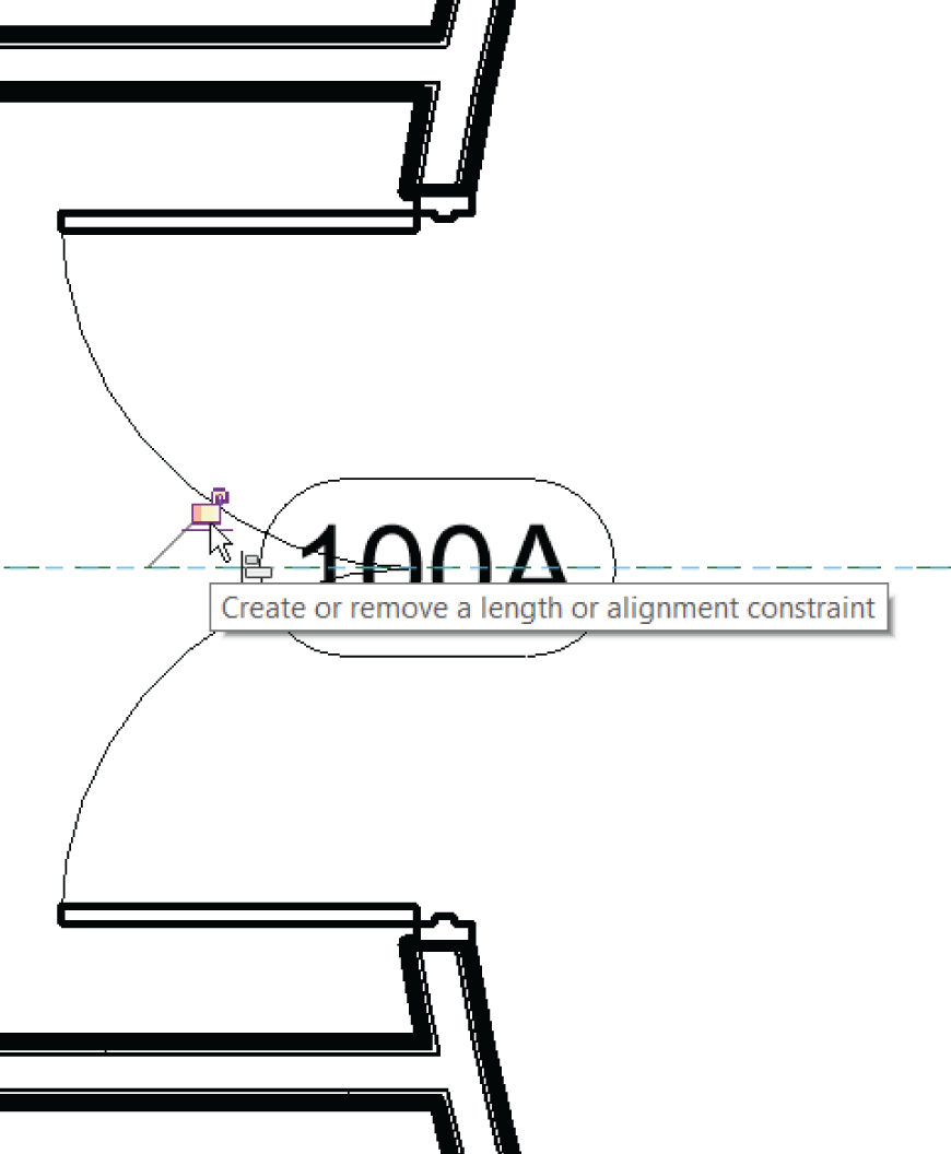
FIGURE 4.33 The door is now aligned and locked.
There will also be times when two items are already aligned and you just want to lock the items together. To do this, you must still use the Align command to access the lock icon.
Now that the Align command is out of the way, you can move on to the next item on the Modify tab: the Split Element command.
The Split Element Command
The Split Element command is the equivalent of the Break command in AutoCAD. You can use the Split Element command on walls and when you edit an element in Sketch Mode.
The objective of this procedure is to cut a notch out of a wall by using the Edit Profile function:
- In the Project Browser, open the Sections (Building Section) called West Wing South Wall Section, as shown in Figure 4.34.
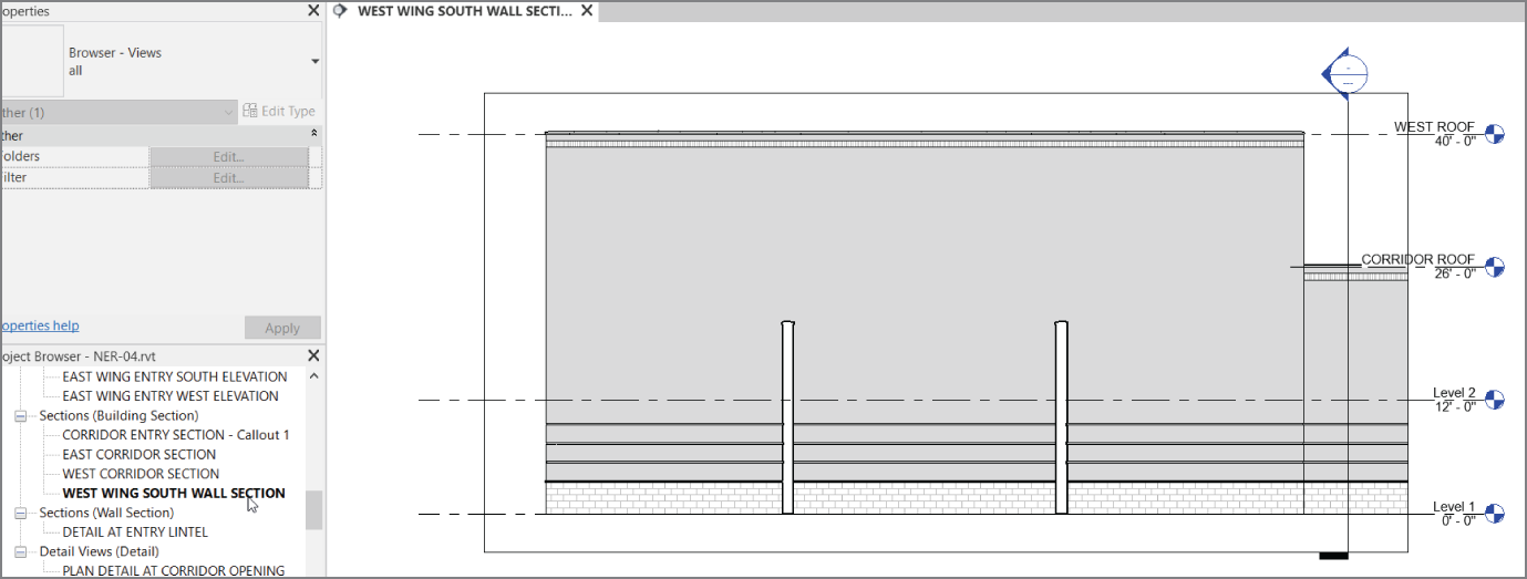
FIGURE 4.34 Open the section called West Wing South Wall Section.
- Select the wall beyond, as shown in Figure 4.35.

FIGURE 4.35 Select the wall beyond, and click the Edit Profile button on the Modify | Walls tab.
- On the Modify | Walls tab, click the Edit Profile button (see Figure 4.35).
After you select the Edit Profile option, you're put into Sketch Mode. You know you're in Sketch Mode because your Ribbon now has a Mode panel with Finish Edit Mode and Cancel Edit Mode options that you must select to return to the full model. Also, the wall you've selected now consists of four magenta sketch lines, and the rest of the model is shaded into the background.
- On the Modify | Walls ➣ Edit Profile tab, click the Split Element button, as shown in Figure 4.36.
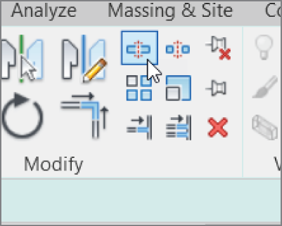
FIGURE 4.36 Select the Split Element button on the Modify | Walls ➣ Edit Profile tab.
- Look at your Options bar. Notice that you can specify that you want to delete the inner segment. Select the Delete Inner Segment check box, as shown in Figure 4.37.
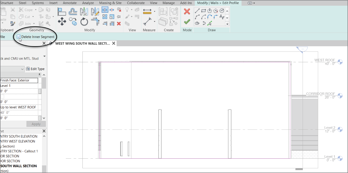
FIGURE 4.37 To remove a segment of a line, you must use the Split Element command and select Delete Inner Segment from the Options bar.
- Pick the intersection of the bottom magenta sketch line and the inside face of the left wall for the first split point (see Figure 4.38).
- Pick the intersection of the bottom magenta sketch line and the inside face of the right wall (see Figure 4.38).
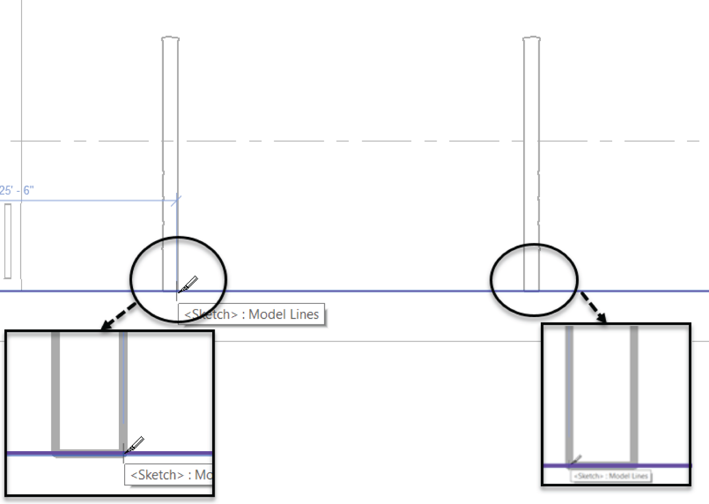
FIGURE 4.38 Splitting the bottom line
After you pick these points, the magenta sketch line is segmented. Now you need to add more lines to the sketch. To do this, leave the Split Element command and follow along by using the sketch tools on the Draw panel:
- On the Draw panel of the Modify | Walls ➣ Edit Profile tab, click the Pick Lines icon, as shown in Figure 4.39.
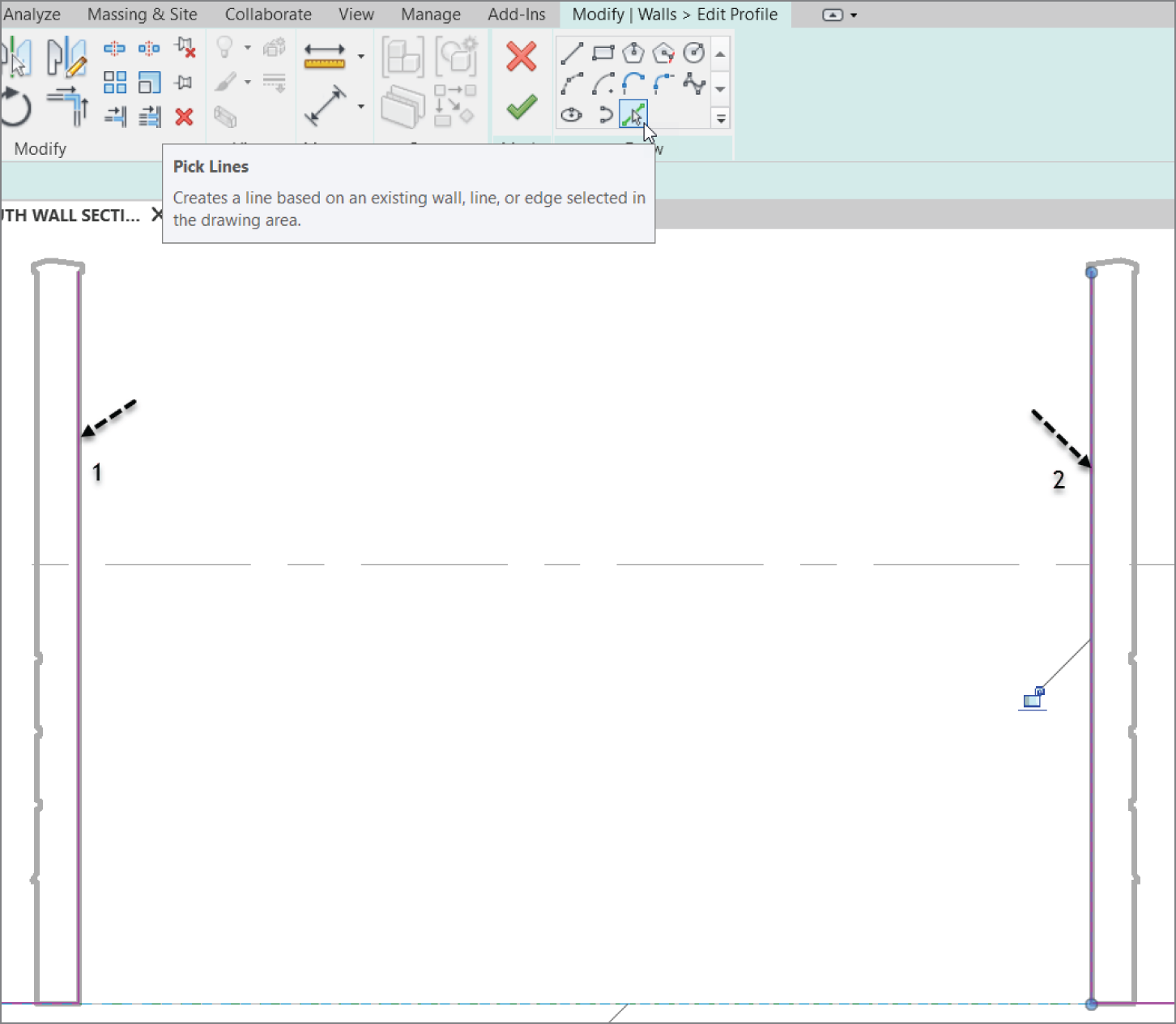
FIGURE 4.39 Tracing the walls to form a notch. This is done by selecting the Pick Lines icon and picking the walls.
- Pick the inside face of the left wall (item 1 in Figure 4.39).
- Pick the inside face of the right wall (item 2 in Figure 4.39).
- Now, select the Line button in the Draw panel as shown in Figure 4.40.
- In the Options toolbar, set the offset to 1′‐0″ (300 mm).
- Pick point #1 to point #2 in Figure 4.40.
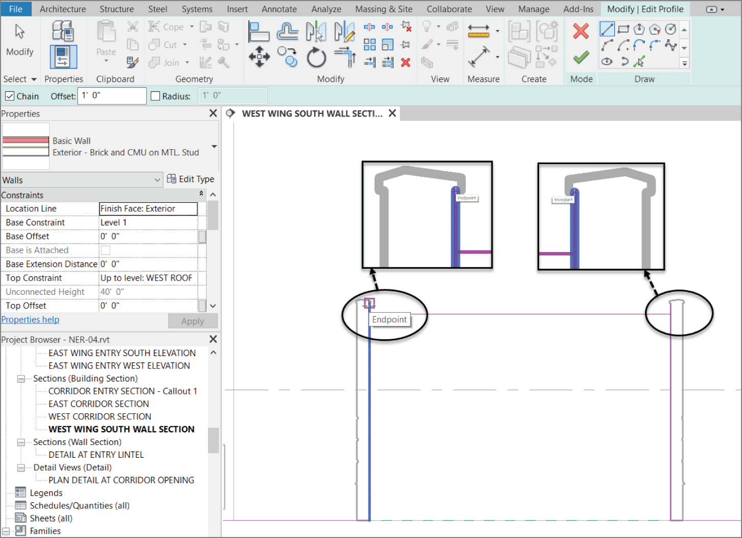
FIGURE 4.40 Drawing the top line with a 1′‐0″ (300 mm) offset
The next step is to get the magenta lines to form a continuous loop. This means there can be no gaps or overlapping lines. Each line starts exactly where the last line ends:
- Press Esc.
- Select the vertical magenta line on the wall to the left.
- Zoom in to the top; notice there is a small blue grip on the end of the line.
- Pick that grip and drag it down so that it meets the horizontal line.
- Repeat the procedure for the right side. See Figure 4.41.
- Click the Green Checkmark (Finish Edit Mode) as shown in Figure 4.42.
- Go to a 3D view to check out your model, as shown in Figure 4.43. You can either click the Default 3D View button on the Quick Access toolbar or pick the {3D} view from the Project Browser.
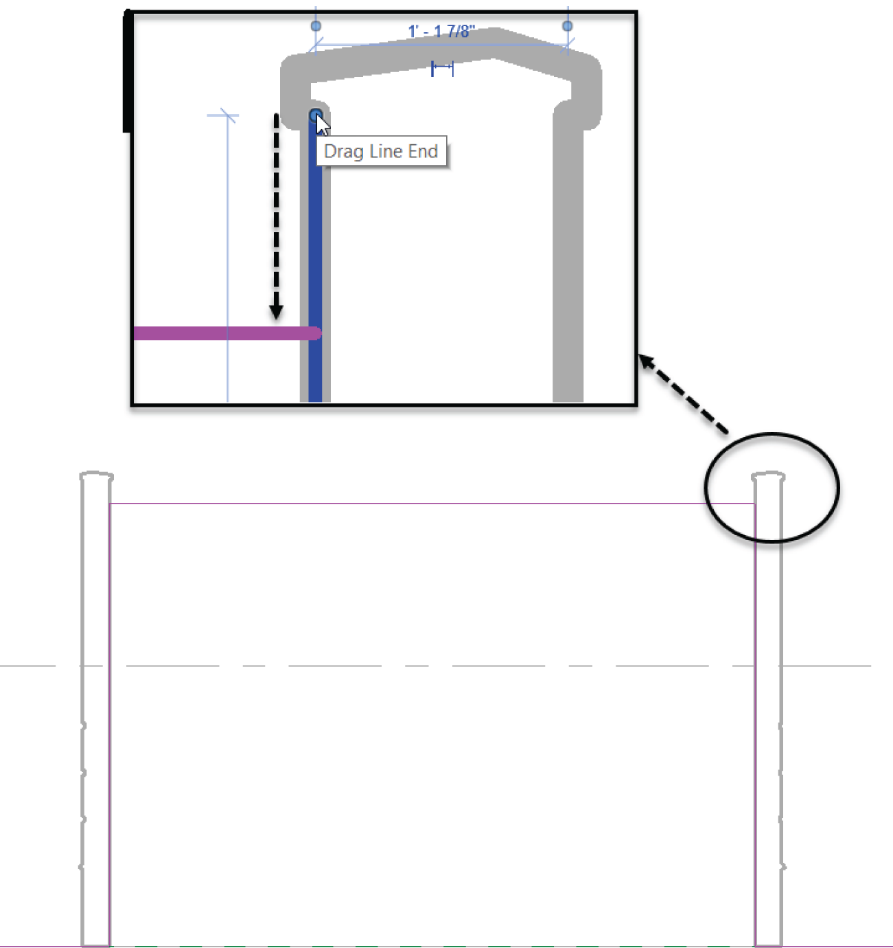
FIGURE 4.41 Modifying the sketch lines by stretching the grips to form a continuous loop
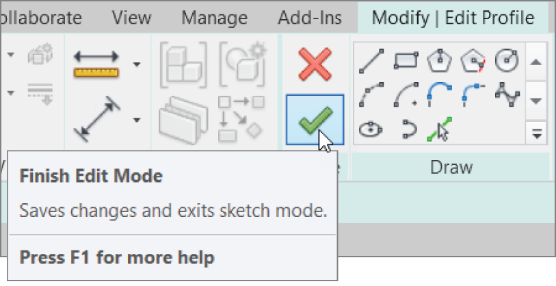
FIGURE 4.42 Click Finish Edit Mode to get back to the model.

FIGURE 4.43 The building in 3D up to this point
The next set of procedures focuses on basic cleanup using the Trim command. Although you can accomplish a lot with this single command, you must get used to a certain Revit method.
The Trim Command
Any time you need to cut or extend an item, you'll use the Trim command. In any design‐based application, you won't get very far without this command. You can use the Trim command on walls and in Sketch Mode, similar to how you would use the Split Element command. As mentioned earlier, however, you need to understand specific procedures to be comfortable using this command.
To use the Trim command, follow along:
- Go to Level 1 under the Floor Plans category in the Project Browser.
- Zoom in on the east wing. Two walls extend beyond their destination. These walls need to be trimmed.
- On the Modify tab, click the Trim/Extend Single Element button, as shown in Figure 4.44.
- Zoom in on the area, as shown in Figure 4.45.
- To trim the vertical wall back to the horizontal wall, you must first pick the wall that you want to trim to (the cutting element). In this case, select the south face of the horizontal wall (see Figure 4.45).
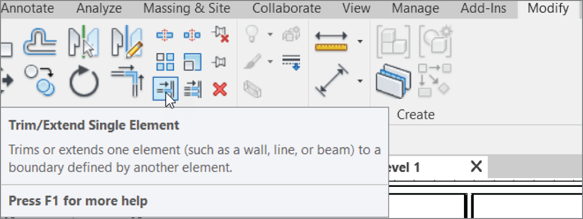
FIGURE 4.44 Click the Trim/Extend Single Element button on the Modify tab.
- Now you must pick a point along the vertical wall. The trick here is that you must pick a point on the side of the wall that you want to keep. Pick a point along the vertical wall above (north of) the horizontal wall, as shown in Figure 4.46. After you do, the wall is trimmed back.
- Press Esc to terminate the command.
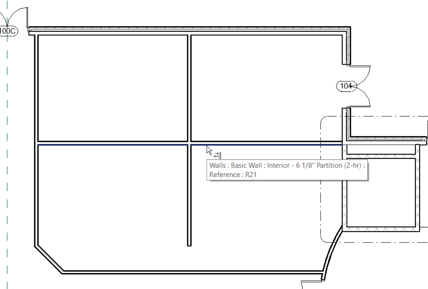
FIGURE 4.45 Zoom into this area to start trimming the walls.
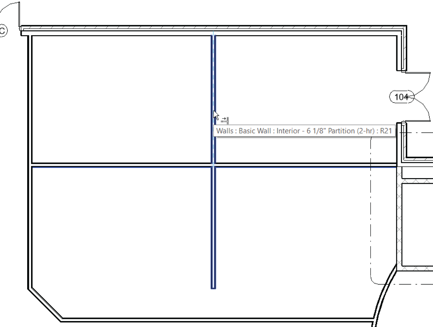
FIGURE 4.46 Pick a point along the wall you want to keep.
You may not always want to trim an item. Often, you need to elongate an item to reach a destination point. In the drafting world, this procedure is better known as extend. The process for using the Extend feature is similar to the Trim command. First, however, you must select the wall to which you want to extend an object and then select the object to be extended:
- Zoom in on the south part of the east wing.
- On the Modify tab, click the Trim/Extend Single Element button.
- Pick the south corridor wall. This is the wall to which you want to extend.
- Pick the vertical wall that doesn't quite intersect. Press Esc, and your walls should now look like Figure 4.47.
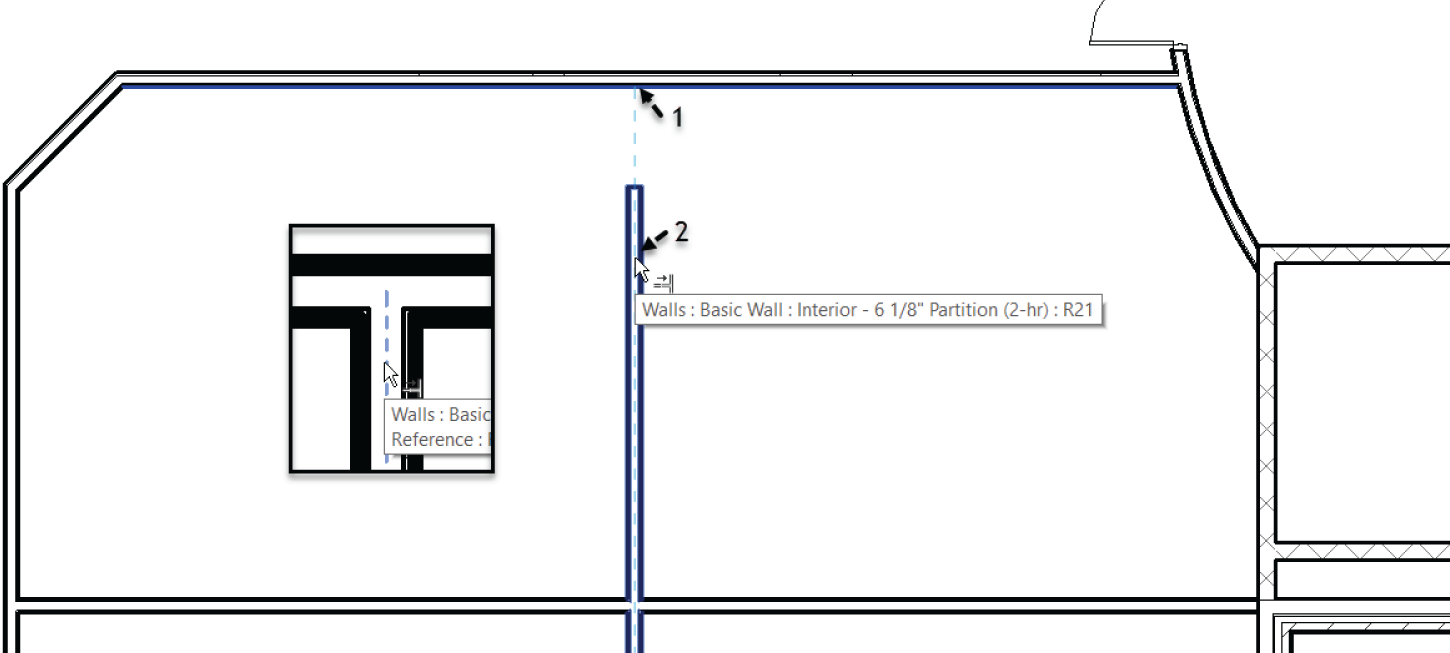
FIGURE 4.47 The finished walls
- Save the model.
There is one more command to examine that is used in the day‐to‐day modification of a Revit model. Most of the commands you've used to place items in the model have had the Offset command built into the options of that specific procedure. The next section focuses on offsetting items by using the stand‐alone Revit Offset command.
The Offset Command
The Offset command enables you to create a copy of a linear item at a specified distance. As mentioned earlier, the need to offset an item crops up much less often in Revit than in a conventional drafting application. This is because in Revit most commands provide offset functionality as an option. Sometimes, however, you need the good‐old Offset command.
To get used to using the Offset command, follow these steps:
- Zoom in on the west part of the east wing. This is the area where the restrooms are located (see Figure 4.48). The objective is to offset the vertical wall that is to the right of the restrooms, to the middle of the open space.
- On the Modify panel of the Modify tab, click the Offset button, as shown in Figure 4.48.
- On the Options bar, click the Numerical button.

FIGURE 4.48 Choosing your options and picking the wall to be offset
- Enter 16′–2″ (4850 mm) in the Offset field.
- Make sure Copy is selected.
- Hover your cursor over the wall to the right of the lavatory, as shown in Figure 4.48. A dashed alignment line appears to the right of the wall.
- Pick the wall. The new wall should be in the middle of the large room.
- Repeat the process for the walls south of the corridor. Your interior should resemble Figure 4.49.
This concludes our discussion of Offset. Because this floor plan consists of items you want to repeat on other floors, you can now explore how to do this by using the Copy/Paste command from Windows.

FIGURE 4.49 Completing the floor plan by using the Offset command will be a common procedure.
Copy/Paste
Yes, this is the actual Microsoft Windows Copy/Paste function. In Revit, you'll use this feature quite a bit. There is no better way to complete a space or a layout on one level and then use that layout on another level than by copying the geometry.
To practice using the Copy/Paste function, you'll select the two lavatories on Level 1, copy them to the Windows Clipboard, and paste them to the remaining floors:
- Zoom into the east wing of the building.
- Select the walls, door, and windows that define both bathrooms. Also select the corridor walls and the radial corridor wall at the east end of the building. Be sure to select the internal doors as well. These selections are shown in Figure 4.50.
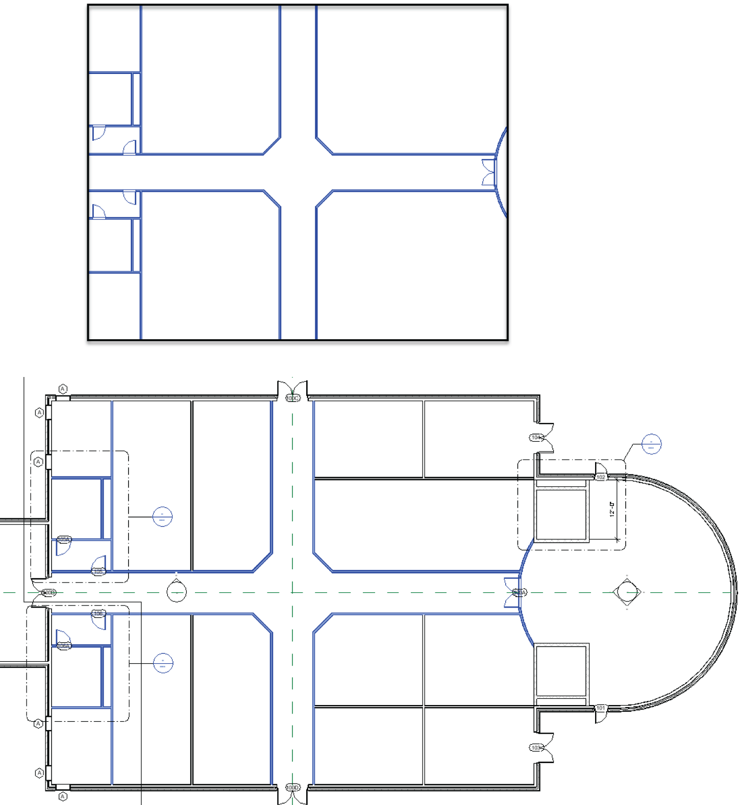
FIGURE 4.50 Selecting the items to be copied to the Clipboard
- Choose Copy To Clipboard from the Clipboard panel of the Modify | Multi‐Select tab (or press Ctrl+C). See Figure 4.51.
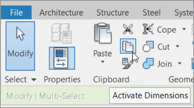
FIGURE 4.51 Good ol' fashioned Copy To Clipboard
- Go to a 3D view.
- On the Clipboard panel of the Modify tab, expand the Paste tool and then click Aligned To Selected Levels, as shown in Figure 4.52.
- In the next dialog, hold down the Shift key and select Floor Plan: Levels 2 through 5 (see Figure 4.52).
- Click OK.
Your model should look like Figure 4.53. If it doesn't, go back and try the procedure again. If you did get it wrong, you can right‐click and choose Select Previous. That way, you don't have to pick around all over again.
The last section in this chapter focuses on actual practice. You now have five floors in the east wing alone, and you must add a layout to them. You also need to add a layout to the west wing.

FIGURE 4.52 The Select Levels dialog enables you to choose the levels to which you're pasting the information.
Creating the Plans
Now that you've added walls, doors, and windows, you can begin to combine this experience with your knowledge of the basic Revit editing commands. In the previous section, you started to lay out your floor plans.
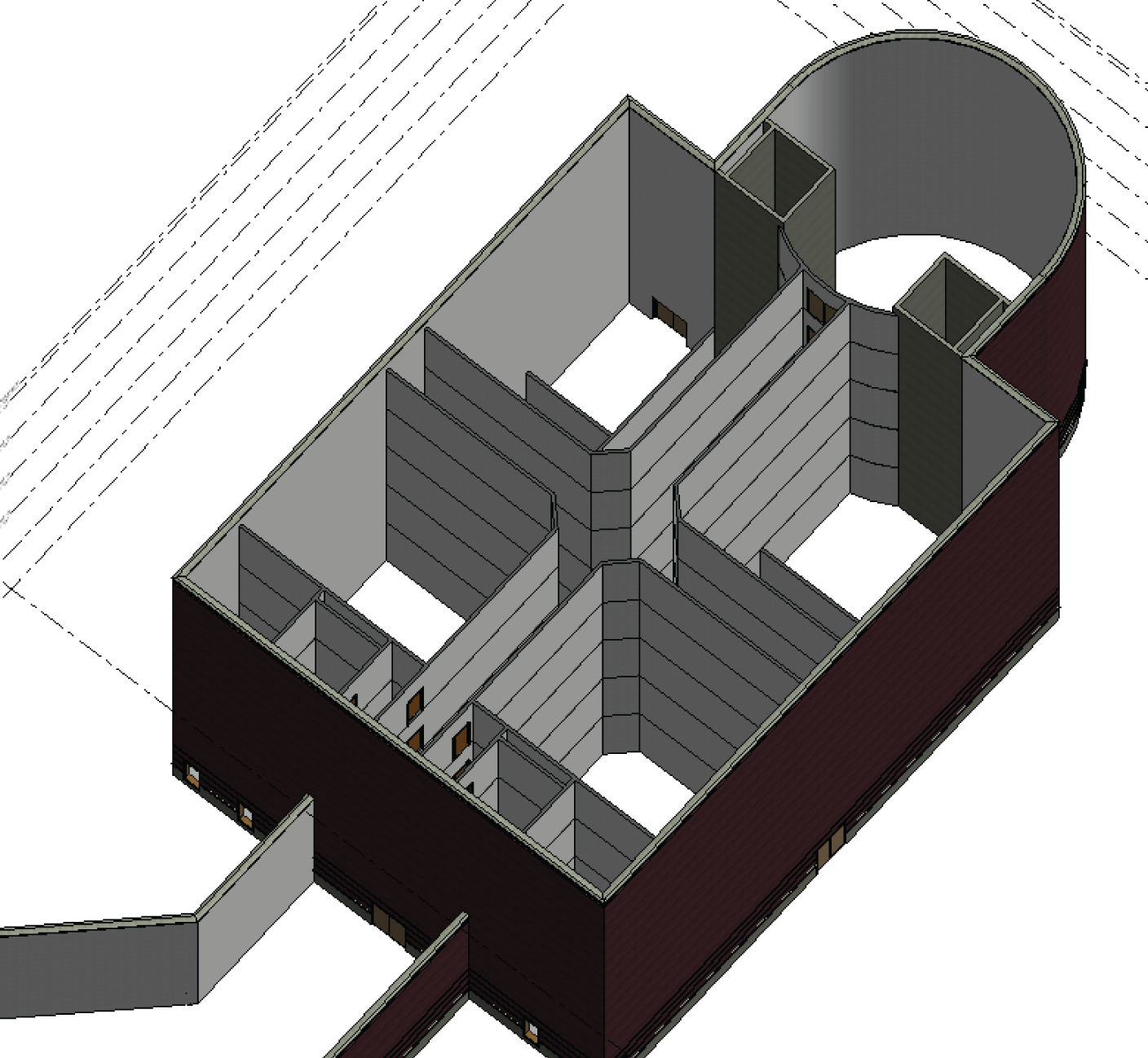
FIGURE 4.53 The east wing is starting to come together.
You can follow along with the book's examples up to floor 3. You can then create your own plans for floors 4 and 5.
To start building a floor plan to be copied to other levels, follow these steps:
- In the Project Browser, go to Level 1 under Floor Plans.
- Add walls, doors, openings, and windows to resemble Figure 4.54. These doors and windows can be any type you like. If your model varies slightly from the example in the book, don't be concerned.
- In the Project Browser, go to Floor Plan Level 2.
- Press Esc to clear any selection.
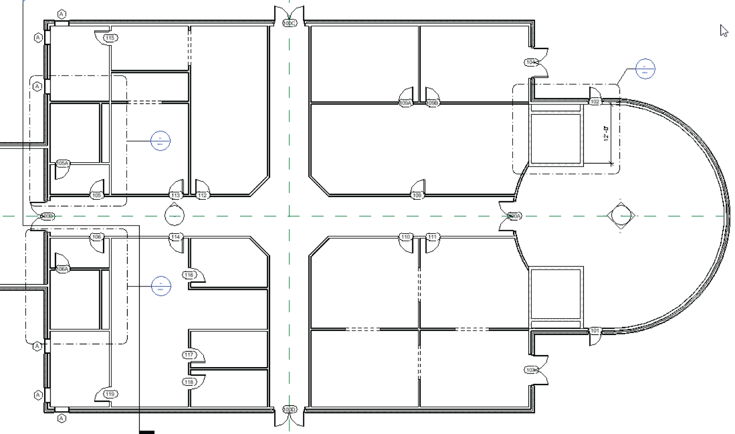
FIGURE 4.54 The first‐floor layout for the east wing
- In the Properties dialog, set Underlay to None, as shown in Figure 4.55. (Underlay is simply the floor below. You can set your underlay to any floor you'd like.)
- Set Detail Level to Fine.
- Create a floor plan layout similar to Figure 4.56. Make all of the dimensions as even and as round as possible. Use all the commands and functions you've learned up to this point.
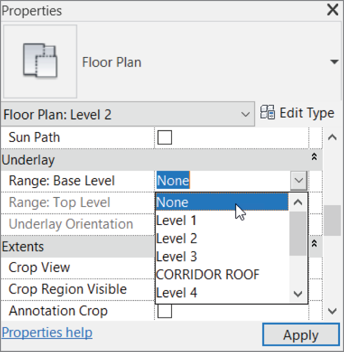
FIGURE 4.55 Switch Underlay from Level 1 to None.
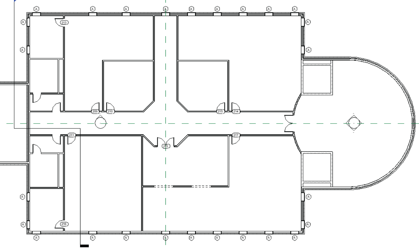
FIGURE 4.56 The layout for Level 2. Try to make the dimensions as even as possible, consistent with what is shown here.
- Select the windows on Level 2, go to a 3D view, and, using Copy and Paste ➣ Aligned To Selected Levels, align them all the way to Level 5. This way, you know your windows are aligned, and you can follow this procedure in your room layout for each floor (see Figure 4.57).
- Go to Level 3, and create a floor plan similar to Figure 4.57. You can do this by using Paste ➣ Aligned To Selected Levels from Level 1. The floor plans are identical, other than the wall configuration in the northwest corner.
- Go to Level 4, and create your own floor plan. The book will give no example. You're on your own!
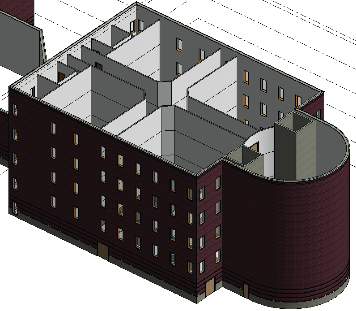
FIGURE 4.57 Using Copy/Paste, align the windows to the higher floors. This will influence your floor layout for each level.
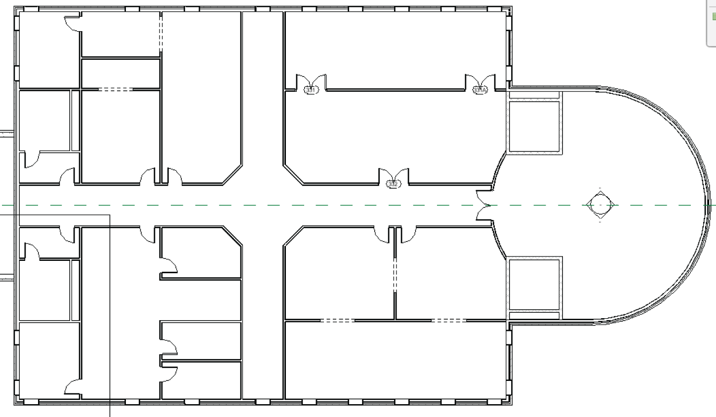
FIGURE 4.58 Level 3: This floor plan was mostly copied from Level 1, with the exception of the east side where the walls conflicted with the windows.
- Create one more floor plan for Level 5. Again, design your own layout. Be as creative as you wish.
- Save the model.
If you got through that last procedure and you're happy with the results, you're well on your way to being efficient in Revit. This is because you just created a floor plan on your own. These last few steps were provided to prove that Revit can be quite intuitive when approached with a little experience.
If you aren't comfortable with your results in this section, that's OK. I had an uncomfortable feeling the first time I did this as well. Take a deep breath, and go back through the steps where you think you got lost.
Are You Experienced?
Now you can…
- use common editing commands to alter the appearance of your model
- use reference planes to establish good, accurate methods of layout
- array items and change the count, length, and radius if needed
- align items and keep them constrained
- use locks to constrain the alignment of one element to another
- split items to remove a segment or to turn one item into two
- use the Copy and Paste ➣ Aligned To Selected Levels commands to create multiple floors that are similar in layout