
Creating a Database Diagram from the Conceptual Model
To create a physical database from the conceptual model you just created, you must open a new Visio document database model diagram. From this new diagram, you add the ORM model. Follow these steps to get started:
1. | From the File menu, select New, Database, Database Model Diagram (US Units). You're now at an empty Database Diagram model, with the Entity Relationships stencil docked to the left of the Visio IDE. |
2. | To add the ORM model, select Project, Add Existing Document from the Database menu. You're prompted with the Add Document to Project dialog box. Navigate to the saved ORM model, which in my case is Drawing1.vsd in the My Documents folder. |
After the drawing is added, the Project pane is docked to the bottom of the IDE as shown in Figure 21.11.
Figure 21.11. Database diagram drawing after adding the ORM model project.

The next step is to generate the physical database from the imported model. Using Visio, you can generate SQL scripts that can execute against a database to create the database, or you can use Visio to create the database and tables for you.
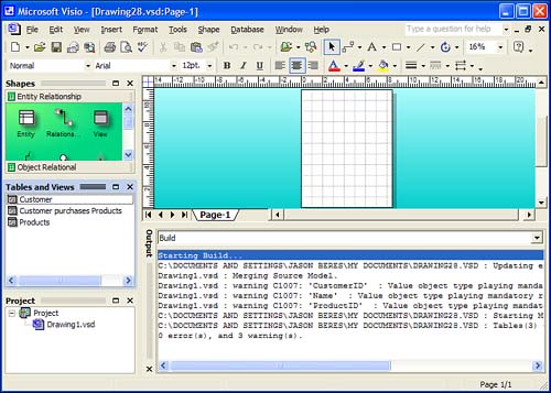
In this case, you're going to let Visio do all the work. The first step is to build the ORM model within the database diagram. To do so, select Build from the Database, Project menu. This step analyzes the facts of the ORM model and turns those facts into physical tables and views. When the build process is complete, your database diagram will have the Tables and Views pane open on the left of the screen (as Figure 21.12 shows) and the Output window will show the results of the build process. The Output window should list something similar to the following:
Starting Build...
C:DOCUMENTS AND SETTINGSJASON BERESMY DOCUMENTSDRAWING28.VSD :
     Updating existing database model project.
Drawing1.vsd : Merging Source Model.
Drawing1.vsd : warning C1007: 'CustomerID'  :
     Value object type playing mandatory role not recommended.
Drawing1.vsd : warning C1007: 'Name'  :
     Value object type playing mandatory role not recommended.
Drawing1.vsd : warning C1007: 'ProductID'  :
     Value object type playing mandatory role not recommended.
C:DOCUMENTS AND SETTINGSJASON BERESMY DOCUMENTSDRAWING28.VSD :
     Starting Mapping ...
C:DOCUMENTS AND SETTINGSJASON BERESMY DOCUMENTSDRAWING28.VSD :
     Tables(3) Columns(9) Logical Keys(9) Foreign Keys(2)
0 error(s), and 3 warning(s).
Figure 21.12. The Tables and Views window shown after you build the ORM model.
From the output, you can see that the build process created three tables, nine columns, and two foreign keys. The tables created are
Customers
Customer Purchases Products
Products
From the Tables and Views window, drag the Customers table onto the drawing surface. When the table is added, right-click it and select Show Related Tables from the contextual menu. At this point, the Customer Purchases Products table is added to the diagram. To add the Products table, you can show the related tables from the Customer Purchases Products table or just drag the table from the Table and Views window onto the drawing surface. You drawing should look something like Figure 21.13.
Figure 21.13. Database diagram after adding tables and views from the ORM model.

You can see that the table relationships are set up and the physical data model is starting to take shape. From what you learned earlier by adding facts to the table, you should be able to ascertain the following concepts:
The CustomerID fact and ProductID fact aren't necessary because adding the entity reference takes care of setting the Primary Key information for the model.
Adding mode value object types for each entity object further populates the database tables with the attributes that make up the entity object.
Creating inverse relationships sets up the foreign key constraints between tables. The Customer Purchases Products table serves as the relationship link between the Customer and Products tables.
Now you can take the next logical step in the process and create the tables in SQL Server for the newly created database diagram.
Creating the Physical Database from the ORM Model
Using Visio, you can create the physical database from the conceptual model in any database that has an ODBC driver on your machine. The easiest way to accomplish this using the tools you have is to create an empty database in SQL Server using Visual Studio .NET, and then use Visio to create the tables using the information from the database diagram.
To do so, open Visual Studio .NET and make the Server Explorer visible. You aren't creating a project, you're just using the tools in the Server Explorer to create a database. After Visual Studio .NET is open, drill into your SQL Servers node. Right-click the NetSDK SQL instance and select New Database from the contextual menu, as Figure 21.14 demonstrates.
Figure 21.14. Getting to the SQL Servers node in Server Explorer.

When you select New Database, the Create Database dialog box pops up. Enter ORM_Test as Figure 21.15 demonstrates and click the OK button to create the new database in SQL Server.
Figure 21.15. Creating a new database using the Create Database dialog box.

Return to Visio, and select Generate from the Database menu. The Generate Wizard dialog now pops up. The Generate Wizard guides you through moving the diagram into an actual database.
In the Generate Wizard dialog box, you have the options of generating the Data Definition Language (DDL) script, generating a new database, and storing the existing model in the database that you create. In this exercise, you're going to select all three options on the first step of the wizard. The dialog box should look like Figure 21.16.
Figure 21.16. The first step of the Generate Wizard in Visio.

After you click the Next button, you're prompted to establish the database connection. Because you already created a database using Visual Studio .NET, select the Database Already Exists option (as Figure 21.17 demonstrates) and click Next.
Figure 21.17. Establishing a connection to the database.

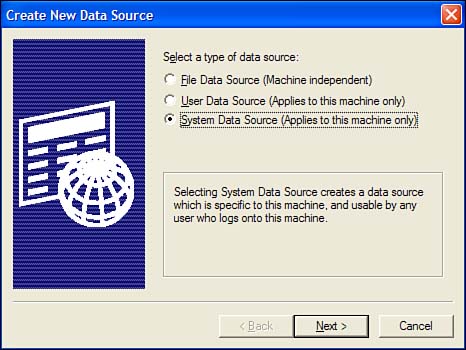
The next screen in the wizard lists the available ODBC connections on your machine. No ODBC connection is set up yet for the ORM_Test database, so click the New button to get the Create New Data Source dialog box as Figure 21.18 shows.
Figure 21.18. Create New Data Source dialog box.
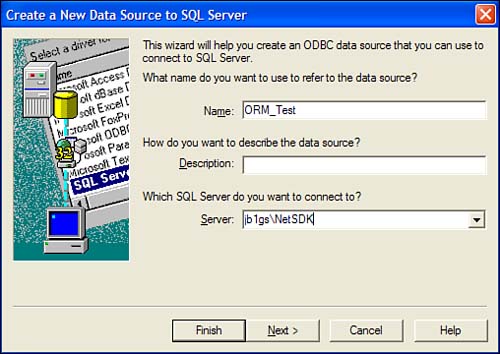
On the first screen of the Create Data Source Wizard, you must enter the friendly name and the server for the database you're connecting. In this case, you can name the data source ORM_Test, and set the server name to your machine nameNetSDK, as you see in Figure 21.19.
Figure 21.19. Setting the name and server for the new data source.
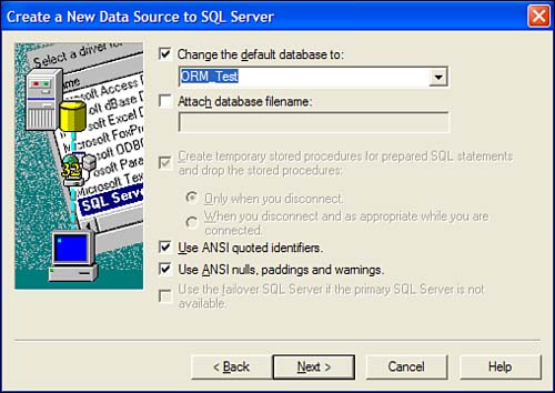
After you click Next, you're taken to the authentication setup for this server. Make sure that Windows Authentication is selected, and click the Next button. At this point, you must change the default database to which you'll be connecting. Click the Change the Default Database To check box and find the ORM_Test database you created earlier in the list, as Figure 21.20 shows.
Figure 21.20. Setting the default database for the ORM_Test database.
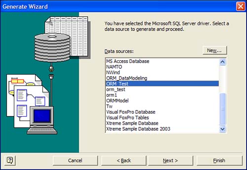
Now you can click Next, Next, and Finish to finalize the creation of the new data source. The data source is created and you're taken back to the Generate Wizard, which lists all the available data sources on your machine. Select the ORM_Test data source, as Figure 21.21 demonstrates, and click the Next button.
Figure 21.21. Selecting the ORM_Test data source in the Generate Wizard.
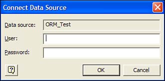
You're now prompted for the authentication information that Figure 21.22 shows. You can click the OK button at this dialog because the data source is set up to use Windows Authentication.
Figure 21.22. Setting the authentication on the data source.
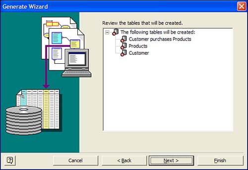
You're given the review list of tables that will be created in the database. Figure 21.23 is what you should see now.
Figure 21.23. Reviewing the tables for the database.
At this point, you can click Finish and the process of Visio connecting to the data source and creating the databases occurs. As the database is being created, your Output window shows the progress of the tables being created and any errors or warnings that occur in the Generate Wizard.
When the generation completes, the Code Editor pops up inside Visio and shows you the DDL scripts that were used to create the physical database. Listing 21.1 is the DDL script that Visio generated to build the ORM_Test database tables.
Listing 21.1. DDL Script Generated by Visio for the ORM_Test Database
If you go back to Visual Studio .NET, you'll see the tables that have been created from Visio. Figure 21.24 shows the Customer table in design mode in SQL Server.
Figure 21.24. Customer table created by Visio in the Server Explorer.
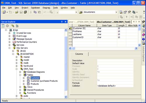
Notice that each of the fields is varchar(10), which isn't desirable in real life. In Visio, you can use the Object Types tab in the Business Rules window to modify data types and the lengths of fields.
Now that the database diagram in Visio has created the physical SQL Server database, you can modify either the model or the database and keep them both in sync using the tools in Visio. That's the two-way street that Visio has with either a database or an ORM diagram: You can manage each project from Visio and update them all from a central location.