
6
Multiple Access Techniques
Multiple access means access to a given facility or a resource by multiple users. In the context of satellite communication, the facility is the transponder and the multiple users are various terrestrial terminals under the footprint of the satellite. The transponder provides the communication channel(s) that receives the signals beamed at it via the uplink and then retransmits the same back to Earth for intended users via the downlink. Multiple users are geographically dispersed and certain specific techniques, to be discussed in this chapter, are used to allow them a simultaneous access to the satellite's transponder. The text matter is suitably illustrated with the help of a large number of problems.
6.1 Introduction to Multiple Access Techniques
Commonly used multiple access techniques include the following:
- Frequency division multiple access (FDMA)
- Time division multiple access (TDMA)
- Code division multiple access (CDMA)
- Space domain multiple access (SDMA)
In the case of frequency division multiple access (FDMA), different Earth stations are able to access the total available bandwidth in the satellite transponder(s) by virtue of their different carrier frequencies, thus avoiding interference amongst multiple signals. The term should not be confused with frequency division multiplexing (FDM), which is the process of grouping multiple base band signals into a single signal so that it could be transmitted over a single communication channel without the multiple base band signals interfering with each other. Here, multiple base band signals modulate different carrier frequencies called subcarrier frequencies and the multiplexed signal then modulates a common relatively higher frequency carrier, which then becomes the signal to be transmitted from the Earth station. Similarly, other stations may also have similar frequency division multiplexed signals with a different final carrier frequency. These multiplexed signals, by virtue of their different final carrier frequencies, are able to access the satellite simultaneously.
In the case of time division multiple access (TDMA), different Earth stations in the satellite's footprint make use of the transponder by using a single carrier on a time division basis. Again it should not be confused with time division multiplexing (TDM), which is the technique used at a given Earth station to simultaneously transmit digitized versions of multiple base band signals over a common communication channel by virtue of their separation on the timescale. The composite time multiplexed signal modulates a high frequency carrier using any of the digital carrier modulation techniques. Multiple time multiplexed signals from other stations having the same carrier frequency are then able to access the satellite by allowing each station to transmit during its allotted time slot.
In the case of code division multiple access (CDMA), the entire bandwidth of the transponder is used simultaneously by multiple Earth stations at all times. Each transmitter spreads its signal over the entire bandwidth, which is much wider than that required by the signal otherwise. One of the ways of doing this is by multiplying the information signal by a pseudorandom bit sequence. Interference is avoided as each transmitter uses a unique code sequence. Receiving stations recover the desired information by using a matched decoder that works on the same unique code sequence used during transmission.
Space domain multiple access (SDMA) uses spatial separation where different antenna beam polarizations can be used to avoid interference between multiple transmissions. Beams with horizontal and vertical or right-hand circular and left-hand circular polarizations may be used for the purpose. Use of the SDMA technique on board a single satellite platform to cover the same Earth surface area with multiple beams having different polarizations allows for frequency re-use. In the overall satellite link, SDMA is usually achieved in conjunction with other types of multiple access techniques such as FDMA, TDMA and CDMA.
6.1.1 Transponder Assignment Modes
In addition to the multiple access techniques outlined in the preceding paragraphs, there are also certain transponder assignment modes. The commonly used ones include:
- Preassigned multiple access (PAMA)
- Demand assigned multiple access (DAMA)
- Random multiple access (RMA)
In the case of preassigned multiple access (PAMA), the transponder is assigned to the individual user either permanently for the satellite's full lifetime or at least for long durations. The preassignment may be that of a certain frequency band, time slot or a code. When it is used infrequently, a link set-up with preassigned channels is not only costly to the user but the link utilization is also not optimum.
Demand assigned multiple access (DAMA) allows multiple users to share a common link wherein each user is only required to put up a request to the control station or agency when it requires the link to be used. The channel link is only completed as required and a channel frequency is assigned from the available frequencies within the transponder bandwidth. It is very cost effective for small users who have to pay for using the transponder capacity only for the time it was actually used. In the case of random multiple access (RMA), access to the link or the transponder is by contention. A user transmits the messages without knowing the status of messages from other users. Due to the random nature of transmissions, data from multiple users may collide.
In case a collision occurs, it is detected and the data are retransmitted. Retransmission is carried out with random time delays and sometimes may have to be done several times. In such a situation, when all the stations are entirely independent, there is every likelihood that the messages that collided would be separated out in time on retransmission.
6.2 Frequency Division Multiple Access (FDMA)
It is the earliest and still one of the most commonly employed forms of multiple access techniques for communications via satellite. In the case of frequency division multiple access (FDMA), as outlined earlier, different Earth stations are able to access the total available bandwidth of satellite transponder by virtue of their different carrier frequencies, thus avoiding interference among multiple signals. Figure 6.1 shows the typical arrangement for carrier frequencies for a C band transponder for both uplink and downlink. The transponder receives transmissions at around 6 GHz and retransmits them at around 4 GHz. Figure 6.1 shows the case of a satellite with 12 transponders, with each transponder having a bandwidth of 36 MHz and a guard band of 4 MHz between adjacent transponders to avoid interference.
Figure 6.1 Carrier frequencies for a C band transponder for both uplink and downlink channels
Each of the Earth stations within the satellite's footprint transmits one or more message signals at different carrier frequencies. Each carrier is assigned a small guard band, as mentioned above, to avoid overlapping of adjacent carriers. The satellite transponder receives all carrier frequencies within its bandwidth, does the necessary frequency translation and amplification and then retransmits them back towards Earth. Figure 6.2 illustrates the basic concept of FDMA in satellite communications. Different Earth stations are capable of selecting the carrier frequency containing messages of their interest. Two FDMA techniques are in operation today. One of them is the multichannel per carrier (MCPC) technique, where the Earth station frequency multiplexes several channels into one carrier base band assembly, which then frequency modulates an RF carrier and transmits it to an FDMA satellite transponder. In the other technique, called the single channel per carrier (SCPC), each signal channel modulates a separate RF carrier, which is then transmitted to the FDMA transponder. The modulation technique used here could either be frequency modulation (FM) in case of analogue transmission or phase shift keying (PSK) for digital transmission.
Figure 6.2 Basic concept of FDMA
Major advantages of FDMA include simplicity of Earth station equipment and the fact that no complex timing and synchronizing techniques are required. Disadvantages include the likelihood of intermodulation problems with its adverse effect on the signal-to-noise ratio. The intermodulation products result mainly from the non-linear characteristics of the travelling wave tube amplifier (TWTA) of the transponder, which is required to amplify a large number of carrier frequencies. The problem is further compounded when the TWTA is made to operate near saturation so as to be able to supply certain minimum carrier power in order to reduce downlink noise and by the fact that the TWTA when operated near saturation exhibits higher non-linearity.
It may be mentioned here that an FDMA system can either be power-limited or bandwidth limited in terms of the number of carriers that can access the satellite transponder. The maximum number of carriers that can access the transponder is given by (n = BTR/BC), where BTR is the total transponder bandwidth and BC is the carrier bandwidth. If the EIRP is sufficient to meet the (C/N) requirements, then the system can support (n) carriers and is said to be bandwidth-limited. In case the EIRP is insufficient to meet the (C/N) requirements, the number of carriers that can access the satellite is less than (n). The system in this case is power-limited.
6.2.1 Demand Assigned FDMA
In a demand assigned FDMA system, the transponder frequency is subdivided into a number of channels and the Earth station is assigned a channel depending upon its request to the control station. Demand assignment may be carried out either by using the polling method or by using the random access method. In the polling method, the master Earth station continuously polls all of the Earth stations in sequence and if the request is encountered, frequency slots are assigned to that Earth station which had made the request. The polling method introduces delays more so when the number of Earth stations is large. In the random access method, the problem of delays does not exist. The random access method can be of two types namely the centrally controlled random access method and the distributed control random access method. In the case of centrally controlled random access, the Earth stations make requests through the master Earth station as the need arises. In the case of distributed control random access, the control is exercised at each Earth station.
6.2.2 Pre-assigned FDMA
In a preassigned FDMA system, the frequency slots are pre-assigned to the Earth stations. The slot allocations are pre-determined and do not offer flexibility. Hence, some slots may be facing the problem of over-traffic, while other slots are sitting idle.
6.2.3 Calculation of C/N Ratio
The overall noise-to-carrier ratio for a satellite link is given by equation 6.1.
Where,
- [N/C]OV = Overall noise-to-carrier ratio
- [N/C]U = Uplink noise-to-carrier ratio
- [N/C]D = Downlink noise-to-carrier ratio
- [N/C]IM = Inter-modulation noise-to-carrier ratio
The value of noise-to-carrier ratio given by equation 6.1 should be less than the required design value of noise-to-carrier ratio [(N/C)REQ], that is
Combining equations 6.1 and 6.2 we get,
In an FDMA system, the up-link noise is usually negligible and the inter-modulation noise is brought to an acceptable level by employing back-off in power amplifiers. It may be mentioned here that the operating point of the power amplifiers mostly TWTA is shifted closer to the linear portion of the curve in order to reduce the inter-modulation distortion. The reduction in the input power is referred to as input back-off and is the difference in dB between the carrier input at the operating point and the saturation input that is required for single carrier operation. The output back-off is the corresponding drop in the output power in dB. Therefore, equation 6.3 can be rewritten as
Equation 6.4 can again be rewritten as
The downlink carrier-to-noise ([C/N]D) is expressed by equation 6.6.
Where,
- [EIRP]D = Satellite Equivalent Isotropic Radiated Power
- [G/T]D = Earth-station receiver G/T
- [LOSSES]D = Free space and other losses at the downlink frequency
- [k] = Boltzmann's constant in dB
- [B] = Signal bandwidth and is equal to the noise bandwidth
Therefore,
In the case of single carrier per channel (SCPC) systems, the satellite will have saturation value of EIRP ([EIRP]sat) and transponder bandwidth of BTR, both of which are fixed. In this case, there is no back-off and equality sign of equation 6.7 applies. Therefore,
Equation 6.8 can be rewritten as
Let us now consider the case of multiple carriers per channel (MCPC) systems having N carriers with each carrier sharing the output power equally and having a bandwidth of B. The output back-off is given by [BO]O. The output power for each of the FDMA carriers is given by equation 6.10.
The transponder bandwidth (BTR) is shared by all the carriers but due to power limitation imposed by the need of back-off, the whole bandwidth is not utilized. Let us assume that the fraction of the bandwidth utilized is alpha (α). Therefore,
Expressing in terms of decilogs
Substituting the values of [EIRP]D and [B] given by equations 6.10 and 6.12 respectively in equation 6.7, we get
Equation 6.13 can be rearranged as
As we can see from equation 6.9, in the case of SCPC system LHS of equation 6.14 is zero. For MCPC systems, it is less than zero.
Therefore,
The best that can be achieved in a MCPC system is to make ![]() .
.
6.3 Single Channel Per Carrier (SCPC) Systems
In the paragraphs to follow, we shall discuss two common forms of SCPC systems namely:
- SCPC/FM/FDMA system
- SCPC/PSK/FDMA system
Each one of them is briefly described below.
6.3.1 SCPC/FM/FDMA System
As outlined earlier, in this form of SCPC system, each signal channel modulates a separate RF carrier and the modulation system used here is frequency modulation. The modulated signal is then transmitted to the FDMA transponder. The transponder bandwidth is subdivided in such a way that each base band signal channel is allocated a separate transponder subdivision and an individual carrier. This type of SCPC system is particularly used on thin route satellite communication networks. Though it suffers from the problem of power limitation resulting from the use of multiple carriers and the associated intermodulation problems, it does enable a larger number of Earth stations to access and share the capacity of the transponder using smaller and more economic units as compared to multiple channels per carrier systems. Another advantage of the SCPC/FM/FDMA system is that it facilitates the use of voice activated carriers. This means that the carriers are switched off during the periods when there is no speech activity, thus reducing power consumption. This in turn leads to availability of more transponder power and hence higher channel capacity. This type of SCPC system also has the advantage that the power of the individual transmitted carriers can be adjusted to the optimum value for given link conditions. Some channels may operate at higher power levels than others, depending on the requirement of back-off for the transponder output power device. It may be mentioned here that the output back-off or simply the back-off of the transponder output power device is the ratio of the saturated output power to the desired output power. However, this type of SCPC system requires automatic frequency control to maintain spectrum centering for individual channels, which is usually achieved by transmitting a pilot tone in the centre of the transponder bandwidth.
Figure 6.3 shows the transmission path for an SCPC/FM/FDMA system. The diagram is self-explanatory. Different base band signals frequency-modulate their respective allocated carriers, which are combined and then transmitted to the satellite over the uplink.
Figure 6.3 Transmission path for the SCPC/FM/FDMA system
The signal-to-noise power ratio (S/N) at the output of the demodulator for the SCPC/FM/ FDMA system can be computed from
where
- C = carrier power at the receiver input (in W)
- N = noise power (in W) in bandwidth B (in Hz)
- B = RF bandwidth (in Hz)
- fd = test tone frequency deviation (in Hz)
- f2 = upper base band frequency (in Hz)
- f1 = lower base band frequency (in Hz)
6.3.2 SCPC/PSK/FDMA System
This is the digital form of the SCPC system in which the modulation technique used is phase shift keying (PSK). SPADE (single channel per carrier PCM multiple access demand assignment equipment) was the first operational SCPC/PSK/FDMA system. It was designed for use on Intelsat-4 and subsequent Intelsat satellites. This system employs PCM for base band signal encoding and QPSK as the carrier modulation technique. With this, it is possible to accommodate a 64 kbps voice channel in a bandwidth of 38.4 kHz as compared to the requirement of a full 45 kHz in the case of frequency modulation. With the use of 45 kHz per channel in QPSK, the guard band is effectively included in this bandwidth, which enables the SPADE system to handle 800 voice channels within a 36 MHz transponder bandwidth. The SPADE system offers the advantage of voice activation described earlier. The ECS-2 (European communications satellite) business service is another example of SCPC/PSK/FDMA system.
The channel capacity can be determined from the carrier-to-noise density ratio. The carrier-to-noise ratio necessary to support each carrier can be computed from
where
- [C/N]th = carrier-to-noise ratio(in dB)at the threshold error rate
- [Eb/N0]th = bit energy-to-noise density ratio(in dB)at the threshold error rate
- [B] = noise bandwidth(in Hz)
- [R] = data rate(in bps)
- [M] = system margin to allow for impairments(in dB)
The carrier-to-noise density ratio [C/N0] can be computed from
where [C/N0] is the total available carrier-to-noise density (in dB) for the transponder
6.4 Multiple Channels Per Carrier (MCPC) Systems
As the name suggests, in this type of multiple access arrangement, multiple signal channels are first grouped together to form a single base band signal assembly. These grouped base band signals modulate preassigned carriers which are then transmitted to the FDMA transponder. Based on the multiplexing technique used to form base band assemblies and the carrier modulation technique used for onward transmission to the satellite transponder, there are two common forms of MCPC systems in use. These are:
- MCPC/FDM/FM/FDMA system
- MCPC/PCM-TDM/PSK/FDMA system Each of them is briefly described in the following paragraphs.
6.4.1 MCPC/FDM/FM/FDMA System
In this arrangement, multiple base band signals are grouped together by using frequency division multiplexing to form FDM base band signals. The FDM base band assemblies frequency modulate pre-assigned carriers and are then transmitted to the satellite. The FDMA transponder receives multiple carriers, carries out frequency translation and then separates out individual carriers with the help of appropriate filters. Multiple carriers are then multiplexed and transmitted back to Earth over the downlink. The receiving station extracts the channels assigned to that station. Figure 6.4 shows the typical block schematic arrangement of such a system, which is suitable only for limited access use. The channel capacity falls with an increase in the number of carriers. Larger number of carriers causes more intermodulation products, with the result that intermodulation-prone frequency ranges cannot be used for traffic.
Figure 6.4 Typical block diagram of the MCPC/FDM/FM/FDMA system (MUX, multiplexer; Rx, receiver; Tx, transmitter)
The signal-to-noise ratio at the demodulator output for such a system is given by:
where
- fd = RMS (root mean square) test tone deviation (in Hz)
- fm = highest modulation frequency (in Hz)
- B = bandwidth of the modulated signal (in Hz)
- b = base band signal bandwidth (in Hz)
- C = carrier power at the receiver input (in W)
- N = noise power (= kTB) in bandwidth B (in W)
6.4.2 MCPC/PCM-TDM/PSK/FDMA System
In this arrangement, multiple base band signals are first digitally encoded using the PCM technique and then grouped together to form a common base band assembly using time division multiplexing. This time division multiplexed bit stream then modulates a common RF carrier using phase shift keying as the carrier modulation technique. The modulated signal is then transmitted to the satellite, which uses FDMA to handle multiple carriers.
6.5 Time Division Multiple Access (TDMA)
As outlined earlier, time division multiple access (TDMA) is a technique in which different Earth stations in the satellite footprint having a common satellite transponder use a single carrier on a time division basis. Different Earth stations transmit traffic bursts in a period time-frame called the TDMA frame. Over the length of a burst, each Earth station has the entire transponder bandwidth at its disposal. The traffic bursts from different Earth stations are synchronized so that all bursts arriving at the transponder are closely spaced but do not overlap. The transponder works on a single burst at a time and retransmits back to Earth a sequence of bursts. All Earth stations can receive the entire sequence and extract the signal of their interest. Figure 6.5 illustrates the basic concept of TDMA. The disadvantages of TDMA include a requirement for complex and expensive Earth station equipment and stringent timing and synchronization requirements. TDMA is suitable for digital transmission only.
Figure 6.5 Basic concept of TDMA
TDMA systems can be classified as preassigned TDMA systems, demand assigned TDMA systems, satellite switched TDMA and limited preassigned TDMA systems. In preassigned TDMA systems, every Earth station is allotted a specific time slot. In a demand assigned TDMA system, the time slots are allotted to the Earth stations on request from the control station. In satellite switched TDMA systems, several antenna spot beams are utilized to provide services to different regions on the Earth's surface. Limited preassigned TDMA is a technique that allows the traffic to be handled during busy hours by demand.
6.6 TDMA Frame Structure
As mentioned above, in a TDMA network, each of the multiple Earth stations accessing a given satellite transponder transmits one or more data bursts. The satellite thus receives at its input a set of bursts from a large number of Earth stations. This set of bursts from various Earth stations is called the TDMA frame. Figure 6.6 shows a typical TDMA frame structure.
Figure 6.6 Typical TDMA frame structure
It is evident from the frame structure that the frame starts with a reference burst transmitted from a reference station in the network. The reference burst is followed by traffic bursts from various Earth stations with a guard time between various traffic bursts from different stations. The traffic bursts are synchronized to the reference burst to fix their timing reference. Different parts of the TDMA frame structure are briefly described in the following paragraphs.
6.6.1 Reference Burst
The reference burst is usually a combination of two reference bursts (RB-1 and RB-2). The primary reference burst, which can be either RB-1 or RB-2, is transmitted by one of the stations, called the primary reference station, in the network. The secondary reference burst, which is RB-1 if the primary reference burst is RB-2 and RB-2 if the primary reference burst is RB-1, is transmitted by another station, called the secondary reference station, in the network. The reference burst automatically switches over to the secondary reference burst in the event of primary reference station's failure to provide reference burst to the TDMA network. The reference burst does not carry any traffic information and is used to provide timing references to various stations accessing the TDMA transponder.
6.6.2 Traffic Burst
Different stations accessing the satellite transponder may transmit one or more traffic bursts per TDMA frame and position them anywhere in the frame according to a burst time plan that coordinates traffic between various stations. The timing reference for the location of the traffic burst is taken from the time of occurrence of the primary reference burst. With this reference, a station can locate and then extract the traffic burst or portions of traffic bursts intended for it. The reference burst also provides timing references to the stations for transmitting their traffic bursts so as to ensure that they arrive at the satellite transponder within their designated positions in the TDMA frame.
6.6.3 Guard Time
Different bursts are separated from each other by a short guard time, which ensures that the bursts from different stations accessing the satellite transponder do not overlap. This guard time should be long enough to allow for differences in transmit timing inaccuracies and also for differences in range rate variations of the satellite.
6.7 TDMA Burst Structure
As outlined above, a TDMA frame consists of reference and traffic bursts separated by the guard time. The traffic burst has two main parts, namely the information carrying portion and another sequence of bits preceding the information data, called preamble. The purpose of preamble sequence of bits is to synchronize the burst and to carry management and control information. The preamble usually consists of three adjacent parts, namely (a) the carrier and clock recovery sequence, (b) the unique word and (c) the signalling channel. The reference burst carries no traffic data and contains only the preamble.
6.7.1 Carrier and Clock Recovery Sequence
Different Earth stations have slight differences in frequency and bit rate. Therefore, the receiving stations must be able to establish accurately the frequency and bit rate of each burst. This is achieved with the help of carrier and clock recovery sequence bits. The length of this sequence usually depends on the carrier-to-noise ratio at the input of the demodulator and the carrier frequency uncertainty. A higher carrier-to-noise ratio and a lower carrier frequency uncertainty require a smaller bit sequence for carrier and clock recovery and vice versa.
6.7.2 Unique Word
Unique word is again a sequence of bits that follows the carrier and clock recovery sequence of bits in the preamble. In the reference burst, this bit sequence allows the Earth station to locate the position of the received TDMA frame. The unique word bit sequence in the traffic burst provides a timing reference on the occurrence of the traffic burst and also provides a timing marker to allow the Earth stations to extract their part of the traffic burst. The timing marker allows the identification of the start and finish of a message in the burst and helps to correct decoding. For obvious reasons, the unique word should have a high probability of detection. For instance, when the unique word of a traffic burst is missed, the entire traffic burst is lost. To achieve this, the unique word is a sequence of 1's and 0's selected to exhibit good correlation properties to enhance probability of detection.
Figure 6.7 shows a type of digital correlator circuit that can be used to detect the unique word bit sequence. Here, the unique word has N bits and is correlated with a stored pattern of itself. The received data is input to one of the N-bit shift registers, as shown in the figure, in synchronization with the data clock rate. The other N-bit shift register has a stored pattern of the unique word. Each stage of the shift register feeds a 2-bit adder, whose output is a ‘0’ if the bits are in agreement and a ‘1’ if they are in disagreement. The outputs of N adders are summed up. The output of the summer is a step function that depends upon the number of agreements or disagreements between the received unique word bit pattern and the stored pattern. The output of summer then feeds a threshold detector that specifies the acceptable number of disagreements. If the number of mismatches is less than or equal to the preset threshold value, the unique word is considered to have been detected. Remember that a declaration of the detection of the unique word occurs at the time instant of reception of the last bit or symbol of the unique word. As mentioned earlier, if the unique word belongs to the reference burst, it marks the TDMA receive frame timing. In the case of traffic burst, it marks the receive traffic burst timing.

Figure 6.7 Digital correlator circuit
6.7.3 Signalling Channel
The signalling channel is used to carry out system management and control functions. The signalling channel of the reference burst has three channels, namely (a) an order wire channel used to pass instructions to and from Earth stations, (b) a management channel transmitted by reference stations to all traffic stations carrying frame management instructions, such as changes in the burst time plan that coordinates traffic between different stations, and (c) a transmit timing channel that carries acquisition and synchronization information to different traffic stations, enabling them to adjust their transmit burst timing (TBT) so that similar bursts from different stations reach the satellite transponder within the correct time slot in the TDMA frame.
The signalling channel of the traffic burst also has an order wire channel, which performs the same function as it does in the case of reference burst. It also has a service channel, which performs functions like carrying traffic station's status to the reference station, carrying information such as the high bit error rate or unique word loss alarms, etc., to other traffic stations.
6.7.4 Traffic Information
Traffic bursts follow the reference burst in the TDMA frame structure. Each station in the TDMA network can transmit and receive many traffic bursts and sub-bursts per frame. The length of each sub-burst, which represents information on a certain channel, depends upon the type of service and the number of channels being supported in the traffic burst. For instance, while transmitting a PCM voice channel that is equivalent to a data rate of 64 kbps, each sub-burst for this channel would be 64 bits long if the frame time available for the purpose was 1 ms.
6.8 Computing Unique Word Detection Probability
As outlined in earlier paragraphs, accurate detection of the unique word is of the utmost importance in a TDMA network. Without going into mathematical details, in this part, an outline will be given of the important mathematical expressions that can be used to compute probabilities of miss detection and false detection. In general, for a given length (in bits or symbols) of unique word, increasing the detection threshold, i.e. the maximum number of acceptable correlation errors, reduces the probability of miss detection but at the same time increases the probability of false detection. On the other hand, lowering the detection threshold to improve the false detection probability increases the probability of miss detection.
In view of this, if the detection threshold is designated as ![]() , the probability of miss detection is nothing but the probability of it having
, the probability of miss detection is nothing but the probability of it having ![]() + 1 or more errors. The probability Pi that i bits or symbols out of N will be in error is given by the binomial distribution as follows:
+ 1 or more errors. The probability Pi that i bits or symbols out of N will be in error is given by the binomial distribution as follows:
where p = average probability of error for receive data.
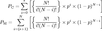
The probability of correct detection PC, which is the sum of probabilities of 0, 1, 2, 3, ..., ![]() errors, and the probability of miss detection PM, which equals (1 − PC), are then given respectively by the following expressions:
errors, and the probability of miss detection PM, which equals (1 − PC), are then given respectively by the following expressions:
The probability of false detection PF is another parameter of interest and can be computed on the basis of the logic that it is the probability of a random string of N bits or symbols accidentally corresponding to the stored unique word pattern to an extent that the number of bits or symbols in disagreement does not exceed the detection threshold. It is only then that there would be a false detection of the unique word. Since there are 2N possible combinations in which random data can occur, the probability of occurrence of the combination matching the stored unique word pattern would be 1/2N. If the detection threshold is ![]() , then 1/2N is also the probability of false detection for
, then 1/2N is also the probability of false detection for ![]() = 0, i.e. random data completely matching the unique word pattern with no correlation errors. In the case where the detection threshold is
= 0, i.e. random data completely matching the unique word pattern with no correlation errors. In the case where the detection threshold is ![]() , the probability of false detection can be computed from
, the probability of false detection can be computed from

The above expression is obvious as the total number of possible combinations in which correlation errors are less than equal to ![]() will be
will be
By analysing the expressions for probabilities of miss detection and false detection, the following observations can be made:
- For a given value of error probability p of the link, the probability of miss detection can be reduced by decreasing the length N of the unique word or by increasing the detection threshold
 . These values are so chosen as to yield PM
  p.
p. - The probability of false detection can be reduced by increasing the length N of the unique word or by decreasing the detection threshold .
6.9 TDMA Frame Efficiency
TDMA frame efficiency is defined as the percentage of total frame length allocated for transmission of traffic data. It is expressed as
where
- Tx = overhead portion of the frame (guard times, preambles)
- Tf = frame length
In the case where the frame has n bursts, Tx can further be expressed as
where
- Tg = guard time between bursts
- Tp,i = preamble of the ith burst
Frame efficiency should be as high as possible. One of the methods to achieve this is to reduce the overhead portion of the frame. This cannot be done arbitrarily. For instance, the carrier and clock recovery sequence must be long enough to provide stable acquisition of the carrier and to minimize the ill effects of interburst interference. Also, the guard time in between the bursts should be long enough to allow for differences in transmit timing inaccuracies and also for differences in range rate variations of the satellite. All these factors need to be considered carefully in any TDMA system design.
Frame efficiency can also be increased by increasing the frame length. However, higher the frame length, larger is the amount of memory needed to perform functions like storing the incoming terrestrial data at a continuous rate for one frame, transmitting the data at a much higher burst bit rate to the satellite, storing the receive traffic bursts and then converting the received data to lower continuous outgoing terrestrial data. Another reason that puts an upper limit on the frame length is that it needs to be kept at a small fraction of the maximum satellite round trip delay of about 274 ms in order to avoid adding a significant delay to the transmission of voice traffic, for which it is usually selected to be less than 20 ms.
6.10 Control and Coordination of Traffic
Two of the most important functions in a TDMA network are controlling the position of the burst in the frame and coordination of traffic between different stations. Both functions are intended to ensure that any change in position and length of bursts does not lead to any burst overlapping or service disruption. Both these functions are performed by the reference station by using the reference burst through the transmit timing channel to control the burst position and the management channel to coordinate traffic between stations.
To do the twin tasks mentioned above, the reference station makes use of what is called a superframe structure. It should be appreciated that to perform control and coordination functions, the reference station has to address all traffic stations in the network. In order to do this in the conventional way, it is observed that it needs a large amount of additional time slots in the reference burst, leading to a reduction in frame efficiency. For instance, if there are N traffic stations, the reference station will need to send N messages to N stations in the transmit timing channel and also another N messages to N stations in the management channel of the reference burst per frame. In order to make transmission and reception of these messages reliable, which is essential, some form of coding is usually employed. One such coding is the 8:1 redundancy coding algorithm where an information bit is repeated eight times in a predetermined pattern and then decoded by using majority decision logic at the receive end. This further increases the time slot required for the purpose eight times. The same is true for the service channel of traffic bursts.
This problem is overcome if the reference station sends one message to one station per frame and the process of sending N messages is then completed in N frames. In other words, station 1 may be addressed by the reference station in frame 1, station 2 in frame 2 and so on, with station N being addressed in frame N. The same procedure can be followed by traffic stations if they have to send a status report to the reference station or some other information to another traffic station. This reduces the lengths of reference burst and traffic burst preambles and increases frame efficiency.
Figure 6.8 shows a typical superframe structure with N frames. There are various ways by which frames can be identified in a superframe. It could be an identification number carried by the management channel in the reference burst with the identification number of frame 1 serving as the superframe marker. Another method is to use different unique words by the reference bursts and traffic bursts to distinguish superframe markers from frame markers.
Figure 6.8 Typical superframe structure with N frames
Having discussed the superframe structure and its significance in performing control and coordination functions, yet another aspect of control and coordination that needs to be addressed is the situation where the number of traffic stations in the network is growing. If the number is fixed or its maximum is known, it is relatively easy for the service channel of traffic bursts to transmit its message over N frames. However, when the number of stations in the network is variable, for instance when the network is growing and the demand assignment mode has been employed for the transponder assignment, it may be appropriate to transmit the messages in the service channel of traffic bursts and demand assignment messages in a separate superframe short burst (SSB) at the superframe rate. In this case, each of the stations in the network transmits a superframe short burst once per superframe; i.e. if station 1 transmits an SSB during superframe 1, station 2 would transmit an SSB during superframe 2 and so on. The advantage of having the service channel in the superframe short burst lies particularly in a situation where a station transmits more than one traffic bursts per frame. Since the messages to be transmitted from a given station through the service channels of traffic bursts in the same frame are likely to be identical, redundancy of messages leads to a reduction in frame efficiency. Figure 6.9 shows the position of the superframe short burst in the superframe structure. The superframe short burst structure is shown in Figure 6.10.
Figure 6.9 Position of superframe short burst in the superframe structure
Figure 6.10 Superframe short burst structure
6.11 Frame Acquisition and Synchronization
Frame acquisition and synchronization, both during the receive and transmit phases, are vital to proper functioning of a TDMA network. While receiving, the station should be able to receive the traffic bursts addressed to it by the satellite transponder(s) in every frame. Similarly, while transmitting, the station should be able to transmit the traffic bursts in such a way that the bursts arrive at the transponder(s) at the correct position within the frame without any overlap with the bursts from other traffic stations.
6.11.1 Extraction of Traffic Bursts from Receive Frames
To ensure a proper receive operation, the traffic station establishes the receive frame timing (RFT), which is defined as the time instant of occurrence of the last bit or symbol of the unique word of the primary reference burst. This sets the time marker from which the location of the traffic burst intended for a given station can be fixed. This is achieved by identifying the receive burst timing (RBT), which is determined by knowing the offset between the receive frame timing reference and the transmit burst timing. The amount offset in bits or symbols is contained in a receive burst time plan, which is stored in the foreground memory of the traffic station. Thus with the help of a receive burst time plan, the traffic station can extract all traffic bursts addressed to it in different frames. This whole process is called the receive frame acquisition.
6.11.2 Transmission of Traffic Bursts
A prerequisite for proper transmission of traffic burst is that it should reach the satellite transponder within the allocated position in the TDMA frame so as not to cause any overlap with traffic bursts transmitted to the transponder by other traffic stations. This can be ensured again by establishing what is called transmit frame timing (TFT) and transmit burst timing (TBT). While the former marks the start of the station's time frame, the latter marks the start of traffic burst. Again, the position of the traffic burst in a transmitted frame is determined by the offset between the transmit frame timing and the transmit burst timing. The information on the offset is contained in the transmit burst time plan stored in the foreground memory of the traffic station. The traffic burst that is transmitted at its transmit burst timing will fall into its appropriate position in the TDMA frame at the transponder. Similarly, traffic bursts from other stations accessing a particular transponder fall into their preassigned or designated positions in the TDMA frame without causing any burst overlapping. This whole process is called transmit frame acquisition.
6.11.3 Frame Synchronization
What has been discussed in the preceding paragraphs is the acquisition of receive frame and transmit frame timings. The acquisition process is needed when a station enters or re-enters operation. The process of maintaining the acquired timing references is synchronization. Synchronization becomes a necessity due to small changes in the satellite orbit caused by a variety of factors. A geostationary satellite orbit may be specified in terms of its inclination angle with the equatorial plane, its eccentricity and its east–west drift. A variation in the inclination angle causes north–south drift and a variation in eccentricity causes a variation in altitude. In the case of a geostationary orbit, the peak-to-peak variation in altitude is 0.2 % of the orbit radius (= 42 164 km), which amounts to about 85 km (0.2 × 42164/100). Peak-to-peak north–south drift and peak-to-peak east–west drift are about 0.2°, which amounts to about 150 km in terms of distance. These errors introduce a maximum range variation of 172 km [= √ (852 + 1502)]. This is equivalent to a one-way propagation delay of 0.575 ms and a round trip maximum delay variation of 1.15 ms. Assuming that the satellite takes about 8 hours to move from its nominal position to a position where maximum delay variation occurs, this leads to a maximum Doppler shift of 40 ns/s. This Doppler shift causes errors in the burst positions as they arrive at the transponder. Thus, frame synchronization is necessary for proper transmission and reception of traffic bursts.
6.12 FDMA vs. TDMA
TDMA and FDMA systems offer some advantages and disadvantages with respect to each other. In this section we present the comparison between the two systems.
6.12.1 Advantages of TDMA over FDMA
- The bit capacity of the TDMA system is independent of the number of accesses.
- The power amplifiers in the transponder of a TDMA system can be operated in the saturation mode as opposed to that of an FDMA system. This increases the capacity of multiple accesses.
- The duty cycle of the Earth station in a TDMA system is low.
- TDMA systems allow the use of digital techniques like digital speech interpolation, satellite on-board switching and so on.
- The TDMA systems offer more flexibility due to use of high-speed logic circuits and processors which offer high data rates.
- TDMA systems are more economical as compared to FDMA systems as they are easy to multiplex, independent of distance and can be easily interfaced with terrestrial services.
- TDMA systems can tolerate higher levels of interference noise.
6.12.2 Disadvantages of TDMA over FDMA
- The peak power of the amplifier in a TDMA system is always large.
- The TDMA system is more complex as compared to the FDMA system. The Earth station of the TDMA system requires ADC, clock recovery, synchronization, burst control and data processing before transmission.
- TDMA systems use high-speed PSK/FSK circuits.
6.13 Code Division Multiple Access (CDMA)
In case of code division multiple access (CDMA), the entire bandwidth of the transponder is used simultaneously by multiple Earth stations at all times. Code division multiple access, therefore allows multiple Earth stations to access the same carrier frequency and bandwidth at the same time. Each transmitter spreads its signal over the entire bandwidth, which is much wider than that required by the signal otherwise. One of the techniques to do this is to multiply the information signal, which has a relatively lower bit rate, by a pseudorandom bit sequence with a much higher bit rate. Interference between multiple channels is avoided as each transmitter uses a unique pseudorandom code sequence. Receiving stations recover the desired information by using a matched decoder that works on the same unique code sequence used during transmission. In the following paragraphs, it will be seen how such a system works.
It is assumed that the message signal is a PCM bit stream. Each message bit is combined with a predetermined code bit sequence. This predetermined code sequence of bits is usually a pseudorandom noise (PN) signal. The bit rate of the PN sequence is kept much higher than the bit rate of the message signal. This spreads the message signal over the entire available bandwidth of the transponder. It is because of this reason that this technique of multiple access is often referred to as spread spectrum multiple access (SSMA). The spread spectrum operation enables the signal to be transmitted across a frequency band that is much wider than the minimum bandwidth required for the transmission of the message signal. The PN sequence bits are often referred to as ‘chips' and their transmission rate as the ‘chip rate'. The receiver is able to retrieve the message addressed to it by using a replica of the PN sequence used at the transmitter, which is synchronized with the transmitted PN sequence.
CDMA uses direct sequence (DS) techniques to achieve the multiple access capability. In this, each of the N users is allocated its own PN code sequence. PN code sequences fall into the category of orthogonal codes. Cross-correlation of two orthogonal codes is zero, while their auto-correlation is unity. This forms the basis of each of the N stations being able to extract its intended message signal from a bit sequence that looks like white noise.
6.13.1 DS-CDMA Transmission and Reception
Figure 6.11 shows the basic DS-CDMA transmitter. The diagram is self-explanatory. The transmitter generates a bit stream by multiplying in the time domain the message bit stream mi(t) and the code information ai(t). Multiplication in the time domain is convolution in the frequency domain. Therefore, the product of mi(t) and ai(t) produces a signal whose spectrum is nothing but convolution of the spectrum of mi(t) and the spectrum of ai(t). Also, if the bandwidth of the message signal is much smaller than the bandwidth of the code signal, the product signal has a bandwidth approaching that of the code signal.
Figure 6.11 Basic block schematic arrangement of the DS-CDMA transmitter
The message signal is either an analogue or a digital signal. In the majority of cases, it is a digital signal. In that case, message signal modulation as shown in the diagram is omitted and the message signal is directly multiplied by the code signal. The resulting signal then modulates a wideband carrier using a digital modulation technique, which is usually some form of phase shift keying.
Figure 6.12 shows the basic block schematic arrangement of the DS-CDMA receiver. The diagram is self-explanatory. It is assumed that the receiver is configured to receive the message signal mi(t). The receiver in this case generates a code signal ai(t) synchronized with the received message. If the signals represented by suffix j constitute undesired signals, i.e. noise, then the bit stream present at the output of the first stage of the receiver and at the input of the demodulator is given by
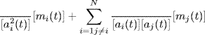
In the case of orthogonal codes,
By substituting these values, it is found that only the first part of the expression for the received bit sequence is the desired one; the remaining part is just noise.
Figure 6.12 Basic block schematic arrangement of the DS-CDMA receiver
A term called processing gain (G) is defined in such systems. It is given by
A chip rate of 2.5 Mbps and a message bit rate of 25 kbps would give a processing gain of 20 dB. Since the undesired component or the noise is spread over the entire bandwidth and the receiver responds only to the 1/G part of this bandwidth, this has the effect of reducing the noise by the same factor. The thermal noise and intermodulation noise are also reduced by the factor G. To sum up, the input to the DS-CDMA receiver is wide band and contains both desired and undesired components. When this received bit stream is applied to the correlator, the output of the correlator is the desired message signal centred on the intermediate frequency. The undesired signals remain spread over the entire bandwidth and only that portion within the receiver bandwidth causes interference. This is further illustrated in Figure 6.13.
Figure 6.13 Signal output of the correlator
In practice, the cross-correlation function is not equal to zero, which leads to some performance degradation. The level of interference is directly determined by the ratio of the peak cross-correlation value to the peak auto-correlation value of the pseudorandom code sequences.
DS-CDMA is further divided into two types, namely:
- Sequence synchronous DS-CDMA
- Sequence asynchronous DS-CDMA
6.13.1.1 Sequence Synchronous DS-CDMA
In the case of the sequence synchronous DS-CDMA system, the message bit duration is chosen to be a certain N times the PN sequence bit duration. This implies that the ratio of the chip rate to message bit rate is N, which is also the processing gain of the system. Also, the system is so synchronized that the PN sequence period of each carrier is time-aligned at the satellite. This is similar to what is done in TDMA, but the synchronization requirements in this case are far less stringent. Here, synchronization in time should be of the order of one-fifth of the PN sequence bit duration. Knowing the timing error caused by the Doppler effect, this sets an upper limit on the maximum usable chip rate.
6.13.1.2 Sequence Asynchronous DS-CDMA
In the case of the sequence asynchronous DS-CDMA system, the message bit duration is chosen to be a certain N times the PN sequence bit duration. The difference between the two systems lies in the fact that here no attempt is made to align the PN sequence period at the satellite. Therefore, there will be time shifts between different carriers. It can be verified that the sequence synchronous DS-CDMA system offers no definite advantage over the sequence asynchronous DS-CDMA system when the user population is much larger than the number of simultaneous users.
6.13.2 Frequency Hopping CDMA (FH-CDMA) System
CDMA is also referred to as spread spectrum multiple access because of the reason that the carrier spectrum is spread over a much larger bandwidth as compared to the information rate. The spread spectrum signal is inherently immune to jamming as it forces the jammer to deploy its transmitted jamming power over a much wider bandwidth than would have been necessary for a conventional system. In other words, for a given power of the jammer, the power spectral density produced by the jammer becomes reduced by a factor of increase in the bandwidth due to spreading. The direct-sequence CDMA discussed in earlier paragraphs is one way to spread the carrier spectrum where the message bit sequence is multiplied by a pseudorandom code sequence. Frequency hopping (FH), to be discussed in the following paragraphs, is another method used to do the same.
In the case of a frequency hopping CDMA (FH-CDMA) system, the carrier is sequentially hopped into a series of frequency slots spread over the entire bandwidth of the satellite transponder. The transmitter operates in synchronization with the receiver, which remains always tuned to the frequency of the transmitter. The transmitter transmits a short burst of data on a narrowband, then tunes to another frequency and transmits again. The transmitter thus hops its frequency over a given bandwidth several times per second, transmitting one frequency for a certain period of time, then hopping to another frequency and transmitting again. This is achieved by using a frequency synthesizer whose output is controlled by a pseudorandom code sequence. The pseudorandom code sequence decides the instantaneous transmission frequency. On the receiver side, the data can be recovered by using an identical frequency synthesizer controlled by an identical pseudorandom sequence. Figures 6.14 and 6.15 show the block schematic arrangements of typical FH-CDMA transmitter and receiver respectively. The diagrams are self-explanatory.

Figure 6.14 Block schematic arrangement of a typical FH-CDMA transmitter
Figure 6.15 Block schematic arrangement of a typical FH-CDMA receiver
Due to the random hopping pattern as governed by the pseudorandom sequence, to an observer, the carrier appears to use the entire transponder bandwidth over the pseudorandom sequence period. At a given instant of time, however, it uses a particular frequency slot. The hopping rate of the carrier may equal the coded symbol rate in the case of slow hop systems or be several times that of the coded symbol rate in the case of fast hop systems. In the case of FH-CDMA, each Earth station is assigned a unique hop pattern. Commonly used modulation schemes in frequency hop CDMA systems include noncoherent M-ary FSK (FSK techniques having M frequency levels) and differential QPSK. Also, non-coherent demodulation is used as it is very difficult to maintain phase coherence between the hops.
6.13.3 Time Hopping CDMA (TH-CDMA) System
In the case of the time hopping CDMA (TH-CDMA) system, the pseudorandom bit sequence determines the time instant of transmission of information. In fact, the signal is transmitted by the user in rapid bursts during time intervals determined by the pseudorandom code assigned to the user. A given user transmits only during one of the M time slots each frame has been divided into. However, the time slot used by a given user for transmission of data in successive frames depends upon the code assigned to it. Since each user transmits its data only during one of the M time slots in each frame, the bandwidth available to it increases by a factor of M. Figure 6.16 shows the block schematic arrangement of a typical TH-CDMA transmitter. The typical receiver block schematic is shown in Figure 6.17.
Figure 6.16 Block schematic arrangement of a typical TH-CDMA transmitter

Figure 6.17 Block schematic arrangement of a typical TH-CDMA receiver
6.13.4 Comparison of DS-CDMA, FH-CDMA and TH-CDMA Systems
The operational principle of the three systems can be illustrated with the help of frequency–time graphs, as shown in Figures 6.18 (a), (b) and (c). These graphs depict the frequency usage of the three systems as a function of time. It is evident from the graph shown in Figure 6.18 (a) that a DS-CDMA system occupies the whole of the available bandwidth when it transmits, whereas an FH-CDMA system uses only a small part of the bandwidth at a given instant of time when it transmits, as shown in Figure 6.18 (b). However, the location of this part differs with time. The bandwidth occupied by an FH-CMDA signal for a given hop frequency depends not only on the bandwidth of the message signal but also on the shape of the hopping signal and the hopping frequency. In the case of a slow hop system, when the hopping frequency is much smaller than the message signal bandwidth, the occupied bandwidth is mainly decided by the message signal bandwidth. In case of a fast hop system, when the hopping frequency is much larger than the message signal bandwidth, the occupied bandwidth is mainly decided by the shape of the hopping signal at a given hopping frequency.

Figure 6.18 Frequency–time graphs of (a) DS-CDMA system (b) FH-CDMA system and (c) TH-CDMA system
In the case of time hopping CDMA (TH-CDMA), depicted in Figure 6.18 (c), as compared to FH-CDMA, the whole of the available bandwidth is used for short time periods instead of parts of the bandwidth being used all the time. To sum up, DS-CDMA uses an entire bandwidth all the time, FH-CDMA uses a small part of the bandwidth at a given time instant but the chosen frequency slot varies with time in order to cover the entire bandwidth and TH-CDMA uses the entire bandwidth for short periods of time.
6.14 Space Domain Multiple Access (SDMA)
So far, multiple access techniques have been discussed that allow multiple Earth stations to access a given transponder(s) capacity without causing any interference among them. In the case of the frequency division multiple access (FDMA) technique, different Earth stations are able to access the total available bandwidth in satellite transponder(s) by virtue of their different carrier frequencies, thus avoiding interference amongst multiple signals. Here each Earth station is allocated only a part of the total available transponder bandwidth. In the case of the time division multiple access (TDMA) technique, different Earth stations in the satellite's footprint make use of the transponder by using a single carrier frequency on a time division basis. In this case, the transponder's entire bandwidth is available to each Earth station on a time-shared basis. In the case of the code division multiple access technique (CDMA), the entire bandwidth of the transponder is used simultaneously by multiple Earth stations at all times. Each transmitter spreads its signal over the entire transponder bandwidth. One of the methods to do so is by multiplying the information signal by a unique pseudorandom bit sequence. Others include frequency hopping and time hopping techniques. Interference is avoided as each transmitter uses a unique code sequence. Receiving stations recover the desired information by using a matched decoder that works on the same unique code sequence as used during transmission.
Space domain multiple access (SDMA), as outlined in the beginning of the chapter, is a technique that primarily allows frequency re-use where adjacent Earth stations within the footprint of the satellite can use the same carrier transmission frequency and still avoid co-channel interference by using orthogonal antenna beam polarization. Also, transmissions from/to a satellite to/from multiple Earth stations can use the same carrier frequency by using narrow antenna beam patterns. As also mentioned earlier, in an overall satellite link, SDMA is usually achieved in conjunction with other types of multiple access techniques such as FDMA, TDMA and CDMA. That is why these techniques were briefly mentioned here again before going into SDMA in a little more detail.
6.14.1 Frequency Re-use in SDMA
Frequency re-use, as outlined above, is the key feature and the underlying concept of space domain multiple access (SDMA). In the face of continually increasing demands on the frequency spectrum, it becomes important that frequency bands assigned to satellite communications are efficiently utilized. One of the ways of achieving this is to re-use all or part of the frequency band available for the purpose. Another way could be employment of efficient user access methods. Yet another approach could be the use of efficient modulation, encoding and compression techniques in order to pack more information into available bandwidths.
Restricting the discussion to frequency re-use, which is the present topic, the two methods in common use today for the purpose are beam separation and beam polarization. Beam separation is based on the fact that if two beams are so shaped that they illuminate two different regions on the surface of the Earth without overlapping, then the same frequency band could be used for the two without causing any mutual interference. One could do so by using two different antennas [Figure 6.19(a)] or a single antenna with two feeds [Figure 6.19(b)].
Figure 6.19 Frequency re-use using beam separation employing (a) Two antennas and (b) Single antenna
Beam polarization, on the other hand, relies on the principle of using two orthogonally polarized electromagnetic waves to transmit and receive using the same frequency band with no mutual interference between the two. Orthogonal polarizations used commonly include horizontal and vertical polarizations or right-hand circular and left-hand circular polarizations.
Both techniques have the capability of doubling the transmission capacity individually, and when used in tandem can increase the capacity four times. SDMA is seldom used in isolation. It is usually used in conjunction with other types of multiple access techniques discussed earlier, including FDMA, TDMA and CDMA. In the following paragraphs, the employment of SDMA separately with each one of these multiple access techniques will be briefly discussed.
6.14.2 SDMA/FDMA System
Figure 6.20 shows a typical block schematic arrangement of the SDMA/FDMA system in which the satellite uses fixed links to route an incoming uplink signal as received by a receiving antenna to a particular downlink transmitter antenna. It is clear from the diagram that the satellite uses multiple antennas to produce multiple beams. The transmitting antenna–receiving antenna combination defines the source and destination Earth stations.
Figure 6.20 Typical block schematic arrangement of an SDMA/FDMA system (DEMUX, de-multiplexer)
The desired fixed links can be set on board the satellite by using some form of a switch, which can be selected only occasionally when the satellite needs to be reconfigured. The links could also be configured alternatively by switching the filters with a switch matrix operated by a command link. It may once again be mentioned here that satellite switches are changed only occasionally when the satellite is to be reconfigured.
6.14.3 SDMA/TDMA System
This system uses a switching matrix to form uplink/downlink beam pairs. In conjunction with TDMA, the system allows TDMA traffic from the uplink beams to be switched to the downlink beams during the course of a TDMA frame. The link between a certain source–destination combination exists at a specified time for the burst duration within the TDMA frame. As an example, the signal on beam 1 may be routed to beam 3 during, say, the first 40 μs of a 2 ms TDMA frame and then routed to beam n during the next 40 μs slot. The process continues until every connection for the traffic pattern has been completed. Figure 6.21 shows a typical transponder arrangement for an SDMA/SS/TDMA system. (SS here stands for ‘satellite switched').
Figure 6.21 Typical transponder arrangement for an SDMA/SS/TDMA system
6.14.4 SDMA/CDMA System
CDMA provides multiple access to the satellite. The satellite receives an uplink CDMA bit stream, decodes it to determine the destination address and then routes it to the desired downlink. The bit stream is usually re-timed, regenerated and stored in onboard processors before it is retransmitted. This implies that a downlink configuration does not need to be the same as the uplink configuration, thus allowing each link to be optimized.
Further Readings
- Calcutt, D. and Tetley, L. (1994) Satellite Communications: Principles and Application, Edward Arnold, a member of the Hodder Headline Group, London.
- Chartant, R.M. (2004) Satellite Communications for the Nonspecialist, SPIE, Washington.
- Elbert, B.R. (1997) The Satellite Communication Applications Handbook, Artech House, Boston, Massachusetts.
- Elbert, B.R. (1999) Introduction to Satellite Communication, Altech House, Boston, Massachusetts.
- Gedney, R.T., Schertler, R. and Gargione, F. (2000) Advanced Communications Technology Satellite: Insider's Account of the Emergence of Interactive Broadband Services in Space, SciTech, New Jersey.
- Gedney, R.T., Schertler, R. and Gargione, F. (2000) The Advanced Communication Technology, SciTech, New Jersey.
- Glibson, J.D. (2002) The Communications Handbook (The Electrical Engineering Handbook Series), CRC Press, Boca Raton, Florida.
- Glisic, S.G. and Leppanen, P.A. (1997) A Handbook for Design, Installation and Service Engineers, Kluwer Academic Publishers.
- Harte, L. (2004) Introduction to CDMA: Network, Services, Technologies, and Operation, Althos.
- Kadish, J.E. (2000) Satellite Communications Fundamentals, Artech House, Boston, Massachusetts.
- Lamb, G. (1998) The TDMA Book, Cordero Consulting Inc.
- Lewis, E.G. (1992) Communication Services via Satellite: A Handbook for Design, Installation and Service Engineers, Butterworth-Heinemann.
- Maral, G. and Bousquet, M. (2002) Satellite Communication Systems: Systems, Techniques and Technology, John Wiley & Sons, Ltd, Chichester.
- Richharia, M. (1999) Satellite Communication Systems, Macmillan Press Ltd.
Internet Sites
- http://www.bee.net/mhendry/vrml/library/cdma/cdma.htm
- http://www.iec.org/online/tutorials/tdma/index.html
- www.sergiochacon.com/Communication/Wireless/Satellite TDMAFDMA.ppt
- http://www.mlab.t.u-tokyo.ac.jp/ mori/courses/WirelessMobileComm2000/CDMA.pdf
- http://www.eas.asu.edu/ junshan/pub/net_capacity.pdf
- http://www.umtsworld.com/technology/cdmabasics.htm
- http://en.wikipedia.org/wiki/Space-division_multiple_access
Glossary
- Code division multiple access (CDMA):
- A multiple access technique in which the entire bandwidth of the transponder is used simultaneously by multiple Earth stations at all times
- Demand assigned multiple access (DAMA):
- A transponder assignment mode that allows multiple users to share a common link, with each user only required to put up a request to the control station or agency for the same as and when it requires to use the link
- Direct sequence CDMA:
- In this form of CDMA, the information signal, which has a relatively lower bit rate, is multiplied by a pseudorandom bit sequence with a much higher bit rate, with the result that the carrier frequency spectrum is spread over a much larger bandwidth. Interference between multiple channels is avoided as each transmitter uses a unique pseudorandom code sequence
- Frequency division multiple access (FDMA):
- A multiple access technique in which different Earth stations are able to access the total available bandwidth in satellite transponder/s by virtue of their different carrier frequencies, thus avoiding interference among multiple signals
- Frequency hopping CDMA:
- In the case of a frequency hopping CDMA system, the carrier is sequentially hopped into a series of frequency slots spread over the entire bandwidth of the satellite transponder. The transmitter hops its frequency over a given bandwidth several times per second, transmitting on one frequency for a certain period of time, and then hopping to another frequency and transmitting again
- Guard time:
- Different bursts are separated from each other by a short time period, known as the guard time, which ensures that bursts from different stations accessing the satellite transponder do not overlap
- Multichannel per carrier FDMA:
- This is a type of FDMA where the Earth station frequency multiplexes several channels into one carrier base band assembly, which then frequency-modulates an RF carrier and transmits it to the FDMA satellite transponder
- Multiple access:
- Multiple access means access to a given facility or resource by multiple users. In the context of satellite communication, the facility is the transponder and the multiple users are various terrestrial terminals under the footprint of the satellite
- Preassigned multiple access:
- A transponder assignment mode in which the transponder is assigned to the user either permanently for the satellite's full lifetime or at least for long durations. The preassignment may be that of a certain frequency band, time slot or a code
- Random multiple access:
- A transponder assignment mode in which access to the link or the transponder is by contention. A user transmits the messages without knowing the status of messages from other users. Due to the random nature of transmissions, data from multiple users may collide. In case a collision occurs, it is detected and the data are retransmitted. Retransmission is carried out with random time delays and sometimes may have to be done several times
- Reference burst:
- The reference burst is used to provide timing references to various stations accessing the TDMA transponder. It does not carry any traffic information
- Signalling channel:
- The signalling channel is used to carry out system management and control functions
- Single channel per carrier FDMA:
- This is a type of FDMA in which each signal channel modulates a separate RF carrier which is then transmitted to the FDMA transponder. The modulation technique used here could either be frequency modulation (FM) in the case of analogue transmission or phase shift keying (PSK) for digital transmission
- Space domain multiple access (SDMA):
- SDMA is a technique that primarily allows frequency re-use where adjacent Earth stations within the footprint of the satellite can use the same carrier transmission frequency and still avoid co-channel interference by using either orthogonal antenna beam polarization or narrow antenna beam patterns
- Spread spectrum communications:
- A technique in which the carrier frequency spectrum is spread over a much larger bandwidth as compared to the information rate. This not only makes the system immune to interception by an enemy but also gives it an anti-jamming capability. CDMA and its different variants employ the spread spectrum technique
- TDMA frame:
- In a TDMA network, each of the multiple Earth stations accessing a given satellite transponder transmits one or more data bursts. The satellite thus receives at its input a set of bursts from a large number of Earth stations. This set of bursts from various Earth stations is called the TDMA frame
- TDMA frame efficiency:
- TDMA frame efficiency is defined as the percentage of total frame length allocated for transmission of traffic data
- Time division multiple access (TDMA):
- A multiple access technique in which different Earth stations in the satellite's footprint make use of a transponder by using a single carrier on a time division basis
- Time hopping CDMA:
- In this form of CDMA, the data signal is transmitted in rapid bursts at time intervals determined by a pseudorandom code sequence assigned to the user. Time hopping CDMA uses a wideband spectrum for short periods of time instead of parts of the spectrum all the time
- Unique word:
- The function of the unique word is to establish the existence of burst and to enable determination of a timing marker, which can be used to establish the position of each bit in remainder of the burst